
Number: UT-PTP7
Revision: 03
TITLE: ISQ-O&G Manual Ultrasonic Thickness &
Corrosion Examination
Date: 07/01/2021
UT-PTP7 Rev. 03 Page 1 of 14 07/01/2021
ISQ-O&G
Manual Ultrasonic
Thickness & Corrosion Examination
ASNT Certification Services, LLC
Document UT-PTP7
Revision 03
The American Society for Nondestructive Testing Certification Services, LLC
All rights reserved
Revision
Date
Summary of Changes
00
05/16/2019
Original Document
01
08/14/2019
Added Appendix A
02
12/19/2019
Additional wording added to Appendix A & Figure 2
03
07/01/2021
Revised thickness range in sections 1.3 & 8.1.2. LLC and Logo changes to the
document.

Number: UT-PTP7
Revision: 03
TITLE: ISQ-O&G Manual Ultrasonic Thickness &
Corrosion Examination
Date: 07/01/2021
UT-PTP7 Rev. 03 Page 2 of 14 07/01/2021
TABLE OF CONTENTS
1. SCOPE
2. REFERENCES
3. ACRONYMS
4. DEFINITIONS
5. QUALIFICATIONS
6. RESPONSIBILITIES
7. EQUIPMENT
8. SPECIMENS
9. STANDARDIZATION
10. EXAMINATION
11. REPORTING
12. APPENDIX A; Signal Evaluation

Number: UT-PTP7
Revision: 03
TITLE: ISQ-O&G Manual Ultrasonic Thickness &
Corrosion Examination
Date: 07/01/2021
UT-PTP7 Rev. 03 Page 3 of 14 07/01/2021
1. SCOPE
1.1. This NDT procedure describes the method for performing manual (non-encoded) pulse-
echo contact straight beam Ultrasonic examinations on carbon steel test specimens
that are utilized in the ASNT Certification Services, LLC ISQ-O&G Ultrasonic
Thickness & Corrosion Scanning exam. This procedure is not applicable for use
outside of the ASNT Certification Services, LLC ISQ-O&G examination.
1.2. The purpose of this procedure is to provide instructions for performing these
examinations to identify the presence of wall loss or mid-wall laminations and to
measure the minimum remaining material wall thickness.
1.3. This procedure is only applicable to carbon steel specimens in the base thickness
range of 0.165” (4.19mm) to 2.500” (63.5mm), for curved specimens of 4” (101.6mm)
diameter or greater up to flat plate, and for bare or coated specimens.
2. REFERENCES
Unless otherwise specified, the latest edition of the below referenced documents are
applicable
2.1. QP-ISQ-2 Industry Sector Qualification Oil & Gas Program
2.2. ASTM E797 Standard Practice for Measuring Thickness by Manual Ultrasonic Pulse-
Echo Contact Method
2.3. SNT-TC-1A Recommend Practice for Personnel Qualification and Certification in
Nondestructive Testing Personnel
2.4. O&G UTT-5 Exam Instructions
2.5. O&G UTT-6 Exam Report Form
3. ACRONYMS
3.1. ANSI American National Standards Institute
3.2. ASNT American Society of Non-destructive Testing
3.3. ASTM American Society for Testing & Materials
3.4. ISQ Industry Sector Qualification
3.5. NDT Nondestructive Testing
3.6. O&G Oil & Gas

Number: UT-PTP7
Revision: 03
TITLE: ISQ-O&G Manual Ultrasonic Thickness &
Corrosion Examination
Date: 07/01/2021
UT-PTP7 Rev. 03 Page 4 of 14 07/01/2021
3.7. UTT Ultrasonic Thickness
4. DEFINITIONS
4.1. Certification Management Committee: The ASNT Certification Services LLC
Committee that has the overall responsibility for developing and maintaining
the technical content of all ASNT Certification Service, LLC certification
programs and shall have the sole responsibility for the determination of
certification outcomes in those programs.
4.2. Industry Sector Qualification (ISQ): A qualification program where practical
demonstration examinations are given to an NDT examiner, for a specific NDT
technique applicable to a given industry sector, to assess competency in performing
examinations. The ISQ shall be awarded upon successful passing of the examination.
4.3. International Services Center (ISC) Certification Group: The ASNT Certification
Services, LLC department responsible for the administration and facilitation of
ASNT Certification Services, LLC certification programs in accordance with
procedures developed by the ASNT Certification Service, LLC Certification
Management Committee (CMC).
4.4. Steering Committee: The group of OG owner/operator subject-matter experts
responsible for the development and maintenance of the ISQ program that fairly and
equitably represents the interests of all parties significantly concerned with the ISQ-
O&G scheme without any particular interest predominating. The parent committee
is the ASNT Certification Services, LLC Certification Management Committee (CMC)
over the Oil & Gas owner/user steering committee for the ISQ-O&G program.
4.5. Test specimen: A sample of a product form containing known discontinuities used
in practical examinations.
5. QUALIFICATIONS
5.1. The ISQ UTT candidates shall understand that the expected prerequisite level of
competency to sit for this exam is at least equal to a Level II ultrasonics limited
certification in A-scan thickness measurement per the guidelines in SNT-TC-1A.
6. RESPONSIBILITIES
6.1. The examination instructions O&G UTT-5 and this examination procedure UT-PTP7,
shall be read and understood by the candidate before applying for the ISQ-O&G UTT
exam. The candidate shall be expected to follow the UTT examination instructions and
the UTT examination procedure during the examination. Failure to do so may cause a
failure on the exam.
6.2. O&G UTT candidates are responsible for bringing and utilizing their own equipment
including: ultrasonic thickness gauge or flaw detector, transducers, cables, reference
standards, couplant, & rags. The candidate is responsible for referring to this

Number: UT-PTP7
Revision: 03
TITLE: ISQ-O&G Manual Ultrasonic Thickness &
Corrosion Examination
Date: 07/01/2021
UT-PTP7 Rev. 03 Page 5 of 14 07/01/2021
procedure and selecting the proper equipment for use during their ISQ UTT exam.
6.3. The candidate shall perform manual (non-encoded) contact straight beam UT
examinations on the ISQ UTT test specimens assigned to them during their exam
which may, or may not, contain service induced or manufactured discontinuities.
6.4. The candidate shall complete their ISQ UTT examination and the associated reporting
in compliance with O&G UTT-5 exam instructions.
6.5. The steering committee and CMC are responsible for this ISQ UTT NDT technique
procedure, and any revisions required for this procedure.
7. EQUIPMENT
7.1. Ultrasonic Instruments
7.1.1. A candidate shall only use an Ultrasonic Thickness Meter with an A-scan
presentation and/or an Ultrasonic Flaw Detector. Digital or Analog
Instruments may be used. A candidate should take the ISQ UTT exam with
the instrument they normally use on a regular basis during their work duties.
Ultrasonic instruments with no A-scan presentation will not be allowed for
use on the ISQ UTT exam, i.e. digital gauges with only a numeric readout.
7.1.1.1. For Instruments with additional B-scan and/or C-scan functions,
the B-scan and/or C-scan functions will have to be switched off
and only the A-scan function shall be utilized during the exam.
7.1.2. Thickness gauging instrumentation should be capable of generating
frequencies within the range of 1 MHz to 10 MHz, with 2.25 MHz to 5 MHz
being the typical range of frequency for use with this procedure.
7.1.3. Ultrasonic instruments used for thickness gauging to this procedure should be
calibrated within the last year.
7.2. Transducers
7.2.1. Straight beam contact or delay line, single and/or dual element, transducers
that are applicable to wall thickness measurements and flaw detection are
acceptable to be used in accordance with this procedure. For Instruments
that have automatic transducer recognition, consult the owner/user manual
for compatibility of the transducer.
7.2.2. Straight beam, pulse echo, single or dual element transducers having element
sizes from 0.125” (3.175mm) to 0.750” (19.05mm), round or square in shape
should be used with this procedure.
7.2.3. The selection of search unit frequency, type, & diameter will depend on the test
specimen thickness and the presence or lack of coating.

Number: UT-PTP7
Revision: 03
TITLE: ISQ-O&G Manual Ultrasonic Thickness &
Corrosion Examination
Date: 07/01/2021
UT-PTP7 Rev. 03 Page 6 of 14 07/01/2021
7.2.3.1. In general, the search unit frequency should be from 2 MHz to 5
MHz. For this exam, thin test specimens or test specimens with
deep corrosion (minimal remaining wall thickness), a higher
frequency is more likely to give more accurate readings. However
very rough corrosion might cause too much scattering of the
Ultrasonic energy at high frequencies, testing at multiple
frequencies may be required. The table below provides frequency
recommendations based on thickness however adequate results
might be achieved outside of these ranges.
Recommended Frequency Ranges
Material Thickness
Frequency (MHz)
< ¼” (6.35mm)
5.0 to 10.0 MHz
¼” (6.35mm) < ¾” (19.05mm)
4.0 to 7.5 MHz
¾” (19.05mm) to < 1 ½” (38.1mm)
2.0 to 5.0 MHz
1 ½” (38.1mm) to < 2 ½” (63.5mm)
2.0 to 5.0 MHz
7.2.3.2. For test specimens under 1” (25.4mm) thickness, a dual element
transducer should be used however consideration should be given
to thin material, under 0.250” (6.35mm) thickness, to ensure no
doubling effect is occurring.
7.2.3.3. For test specimens 1” (25.4) and greater in thickness, a single
element transducer should be used however a dual element
transducer with sufficient focal depth might be adequate to
achieve accurate results.
7.2.3.4. Consideration for test specimen curvature should be given when
selecting transducers for examination. Transducers should be
selected that will sit flat on curved surfaces to minimize errors due
to transducer rocking. Curved exam specimens shall not be less
than ANSI 4” outside diameter pipe sections.
7.3. Couplant
7.3.1. A suitable couplant designed for use in ultrasonic testing should be used for
the exam. The couplant shall be of a type that can be easily cleaned off
specimens with wiping a rag across the surface.
7.3.2. The same couplant that is used for equipment standardization should be used
for examination.
7.3.3. All couplant shall be cleaned off specimens before being returned to the
specimen holding area.

Number: UT-PTP7
Revision: 03
TITLE: ISQ-O&G Manual Ultrasonic Thickness &
Corrosion Examination
Date: 07/01/2021
UT-PTP7 Rev. 03 Page 7 of 14 07/01/2021
7.4. Reference Standards
7.4.1. Reference standards with flat, parallel surfaces, should be used. They should
have thin and thick sections that fully cover the range of specimen thickness
to be inspected. Multiple reference standards might be required to cover the
full range of specimen thickness included in this exam.
7.4.2. Reference standards should be certified with known thickness values.
7.4.3. Reference standards should have similar acoustic properties as the low alloy
carbon steel test specimens.
8. SPECIMENS
8.1. Test Specimens in the ISQ UTT exam shall have the following characteristics:
8.1.1. They shall be low alloy carbon steel.
8.1.2. The thickness range of UTT test specimens shall be from 0.165” (4.19mm) to
2.5” (63.5mm).
8.1.3. Test specimens shall be of either flat plate or curved section product form.
Curved section specimens shall not have a radius smaller than that of an
ANSI 4” outside diameter pipe.
8.1.4. Test specimens may be coated with 10 to 50 mils of coating: fusion bonded
epoxy, two-part polyurethane, or similar.
9. STANDARDIZATION
9.1. The ultrasonic instrument should be standardized (often referred to as calibrated or
technique calibration) for horizontal linearity (thickness) on reference standards
having similar acoustic properties as the low alloy carbon steel test specimens.
9.2. Reference standards should have a minimum of 2 (two) sections of different thickness
which cover the minimum and maximum thickness range expected for the specimen(s)
to be examined. The more steps that are machined into a reference standard and used
for standardization, the better the accuracy of the instrument standardization will be.
9.3. The ultrasonic instrument shall be standardized prior to examination and should be
standardized upon completion.
9.4. The technician should also check their instrument standardization anytime during
their examination when one of the following conditions occur:
9.4.1. Any equipment component is changed: transducer, cable, delay line standoff,
battery, etc.

Number: UT-PTP7
Revision: 03
TITLE: ISQ-O&G Manual Ultrasonic Thickness &
Corrosion Examination
Date: 07/01/2021
UT-PTP7 Rev. 03 Page 8 of 14 07/01/2021
9.4.2. The technician doubts the accuracy of their standardization.
10. EXAMINATION
10.1. Specimen surface condition:
10.1.1. Prior to examination the test specimens should be visually examined, in the
area to be contacted by the transducer, to ensure the scanning surface is free
of couplant residue, loose paint, dirt, mill scale, machining or grinding
particles, or other loose foreign matter that would impair the free movement of
the transducer or affect the accuracy of the thickness measurement results.
10.2. Place transducer on test specimen and move it across the surface to see the average
backwall signal amplitude. Adjust instrument gain to achieve an 80-100% full screen
height signal amplitude of the first back wall reflection for the specific test specimen
under examination. This should be used as the base gain setting for examination of
this test specimen.
10.2.1. Scanning may be performed with an additional +6dB for greater sensitivity to
detect small discontinuities.
10.2.2. Additional gain above base and scanning dB may be needed to evaluate small
indications. Care should be taken in distinguishing between real indications
and background noise in the A-scan when adding gain.
10.3. Each test specimen shall be examined from the scanning surface only to determine the
presence and type of any discontinuities (flaws) in the specimen by scanning the entire
specimen. Possible flaw types are detailed in 11.1.1. No specimens shall include
flaw types from more than one of the three categories detailed in 11.1.1.
10.3.1. Scanning speed should not exceed 6” (152.4mm) per second.
10.3.2. Scanning overlap should be a minimum of 10% of the width or diameter of the
active area of the transducer.
10.4. For test specimens with coating the following methods should be utilized to accurately
measure the minimum and maximum wall thickness.
10.4.1. Measurement calculated by subtracting the first back wall signal from the
second back wall signal. This can be accomplished either by an instrument’s
Echo to Echo function or by manually subtracting the value observed from the
first back wall signal from the value observed from the second back wall
signal.
Note: When using echo to echo, many instrument manufacturers warn users about potential
signal mode conversion that can occur when measuring thicknesses above 0.7". When

Number: UT-PTP7
Revision: 03
TITLE: ISQ-O&G Manual Ultrasonic Thickness &
Corrosion Examination
Date: 07/01/2021
UT-PTP7 Rev. 03 Page 9 of 14 07/01/2021
this occurs, a mode converted shear wave signal can appear before the second backwall
reflection, which can trigger the instrument to focus on it, rather than the true second
backwall reflection, yielding a thinner reading than is actually present.
10.4.2. In some cases, such as on test specimens with rough back wall surfaces, the
echo-to-echo function might not work due to the inability to produce multiple
back wall reflections. As an alternative option for acquiring accurate wall
thickness readings through coating without multiple backwall signals the
following method may be utilized for each individual specimen:
10.4.2.1. Examine the test specimen in the standard first back wall method
to identify areas without wall loss adjacent to the area(s) with wall
loss.
10.4.2.2. Record the measurement of the test specimen with coating in the
standard first back wall technique in an area with no wall loss.
10.4.2.3. Then record a measurement in the same area with no wall loss
utilizing the method in 10.4.1 above to measure the wall thickness
without coating.
10.4.2.4. Subtract the wall thickness reading without coating (echo to echo
method) from the wall thickness measurement with coating
(standard first back wall method) and record the difference. This
recorded value is the equivalent coating thickness as measured by
the UT instrument calibrated for carbon steel.
10.4.2.5. Scan the entire test specimen in the standard first back wall
method to locate the minimum remaining wall thickness.
10.4.2.6. Subtract the previously recorded value for the coating thickness
from the minimum wall thickness observed in the standard first
back wall technique.
10.4.2.7. This method should only be utilized when it is impossible to
acquire a second multiple back wall signal.
10.5. Utilize the examination dry erase specimen sketch note sheet provided by the AEP to
record notations during the exam. Transfer recorded notes / answers from the
specimen sketch note sheet to the dry erase report form O&G UTT-6, also provided by
the AEP, for data recording during the exam.
10.6. Clean off all residual couplant from test specimens before returning them to the
holding area and retrieving any subsequent specimens.
11. REPORTING
11.1. During the exam, the dry erase report form provided by the AEP shall be used for

Number: UT-PTP7
Revision: 03
TITLE: ISQ-O&G Manual Ultrasonic Thickness &
Corrosion Examination
Date: 07/01/2021
UT-PTP7 Rev. 03 Page 10 of 14 07/01/2021
recording examination results. The following details shall be recorded for each test
specimen:
11.1.1. The flaw type determined shall be recorded in the ‘flaw type’ data entry
location for the corresponding specimen by the candidate. The flaw type
options for data entry for each specimen are as follows; ‘N’ for a specimen with
no damage observed, ‘W’ for a specimen observed as containing any form of
wall loss, or ‘M’ for a specimen with one or multiple mid-wall laminations
observed. See Appendix A for more information on signal evaluation.
11.1.2. For test specimens identified as containing wall loss, the minimum remaining
wall thickness for the entire test specimen shall be determined and recorded
in the ‘minimum thickness’ data entry location for the corresponding
specimen by the candidate.
11.1.3. For test specimens identified as containing (a)mid-wall lamination(s), the
minimum remaining full wall thickness for the entire test specimen shall be
determined and recorded in the ‘minimum thickness’ data entry location for
the corresponding specimen by the candidate. The depths or horizontal
dimensions of the mid-wall lamination(s) shall not be recorded.
11.1.4. For test specimens identified as containing no damage, the minimum
remaining wall thickness for the entire test specimen shall be determined and
recorded in the ‘minimum thickness’ data entry location for the corresponding
specimen by the candidate.
11.1.5. The maximum thickness shall be determined for each test specimen, from all
flaw type categories, and recorded in the ‘maximum thickness’ data entry
location for the corresponding specimen by the candidate.
11.2. After examination completion the candidate shall follow the instructions provided in
O&G UTT-5 Exam Instructions to complete their computerized report entry and
submission to the ASNT Certification Services, LLC computerized grading system. Or
in the case of an issue with the computerized report submission system, follow the
AEP’s instructions for hard copy report completion and submission.
11.3. Once report submission is completed the candidate shall clean off the dry erase forms
provided and turn them into the AEP.

Number: UT-PTP7
Revision: 03
TITLE: ISQ-O&G Manual Ultrasonic Thickness &
Corrosion Examination
Date: 07/01/2021
UT-PTP7 Rev. 03 Page 11 of 14 07/01/2021
Appendix A – Signal Evaluation
Careful evaluation of A-scan signals is required to differentiate signal responses generated by wall
loss from signal responses generated by mid-wall laminations or inclusions. Below is some guidance
that can be used to assist with signal evaluation to identify if signal responses are from wall loss or
from mid-wall reflectors. The information provided is guidance only and should not be considered
as absolute for all situations. All items below should be considered when evaluating ultrasonic 0-
degree signal responses from unknown reflectors.
1. Laminations generate signals that are typically higher in amplitude, narrow on the time
base, and have a flat vertical leading edge, similar to a flat back wall response:
a. Sharp, flat leading edge to the signal.
b. Signal has little to no movement horizontally across A-scan display from variation in
sound path. Laminations are at a constant, or near constant, depth and therefore rise
and fall at the same location on the time base.
c. Large laminations close to the surface can have a signal amplitude larger than the
backwall signal from the full material thickness.
d. Laminations almost always create multiple, or repeat, signals in equidistant steps
from the scanning surface. Coated samples are an exception to this guidance as
ultrasonic signals through coating may have considerable ring down, additional cycles
in the sine wave, in the first back wall response that greatly reduce the level of
continued energy required to create multiple back wall signals.
e. Signal responses from laminations are consistent in shape, size, & time base location
regardless of the scanning direction the transducer moves on and off of the lamination
from.
f. Multiple laminations of various sizes and at various depths in one material can be
mistaken as corrosion covering a range of depth. Care must be taken to evaluate these
signals individually to verify they are laminations. These situations are often seen in
older equipment with many small mid-wall laminations.
g. Laminations are most likely contained within the middle half of the material and are
very unlikely to be close to the front or back-wall surface.
2. Areas of wall loss generate signals that are typically lower in amplitude than back-wall
echoes and are broad with multiple peaks:
a. Rough, wide signals, with multiple peaks.
b. Corrosion signals move left of the back-wall signal along the time base.

Number: UT-PTP7
Revision: 03
TITLE: ISQ-O&G Manual Ultrasonic Thickness &
Corrosion Examination
Date: 07/01/2021
UT-PTP7 Rev. 03 Page 12 of 14 07/01/2021
c. Corrosion signals with substantial change in depth likely have responses that move
across a significant amount of the time base.
d. Very unlikely to have amplitude larger than the back-wall. If wall loss is very deep
(close to scanning surface) and has a large plateau (flat area) then it is possible to have
a larger amplitude than a back-wall response, but this is very rare.
e. Corrosion is very unlikely to create multiple, or repeat, signals. If wall loss is very deep
(close to scanning surface) and has a large plateau (flat area) then it is possible, but
this is also very rare. Samples with erosion that have a smooth area that is parallel to
the scanning surface are an exception to this guidance. These types of areas can
generate multiple reflection signals like a lamination. However, areas of erosion will
generate changes in signal behavior when moving the transducer on and off of the
eroded area in various scanning directions unlike laminations which will generate the
same signal behavior in every direction as the transducer is moved on and off of the
area containing the lamination.
f. Shallow internal pitting can be seen in small changes to the back-wall signal. Monitor
drops in signal amplitude in conjunction with slight movement to the left on the time
base line.
g. Shallow pitting and corrosion will generate signals close to the full sample back-wall
thickness at undamaged areas.
h. Isolated areas of corrosion with steep sides to the wall loss (i.e. large single pits) can
generate A-scan signals similar to large laminations where the back-wall signal
disappears completely, and a signal appears with shorter sound path. In a situation
where this occurs, care must be taken to verify if there is any movement on the time
base to the left (shorter sound path) along with reduced amplitude of the back-wall
signal and/or a slight movement to the left (shorter sound path) along with increasing
amplitude of the mid-wall signal. If either of these conditions occur the reflector is
likely an isolated pit with significant wall loss rather than a mid-wall lamination.
3. Coated parts can cause additional difficulties in signal evaluation:
a. Coating can cause an increase in signal ring-down, additional cycles in the sine wave,
which makes all signals seem broader with an increased number of signal cycles seen
on the A-scan. This makes all signals, including clean back-wall signals and
laminations, to appear broader. Coating on samples that creates additional signal
ring-down can also cause laminations to not generate multiple signals.
b. Extra care must be taken on coating parts when evaluating signals from laminations
to verify they do not move back and forth on the time base.

Number: UT-PTP7
Revision: 03
TITLE: ISQ-O&G Manual Ultrasonic Thickness &
Corrosion Examination
Date: 07/01/2021
UT-PTP7 Rev. 03 Page 13 of 14 07/01/2021
Figure 1 – Signal Patterns (© ASNT 2019)
The following figure provides some examples of signal patterns indicative of the various scenarios
detailed. The figure assumes a back-wall signal from an undamaged area on a part was set to 80%
full screen height at a position on the time base 40% across the screen from the left side (0
distance).
Number: UT-PTP7
Revision: 03
TITLE: ISQ-O&G Manual Ultrasonic Thickness &
Corrosion Examination
Date: 07/01/2021
UT-PTP7 Rev. 03 Page 14 of 14 07/01/2021
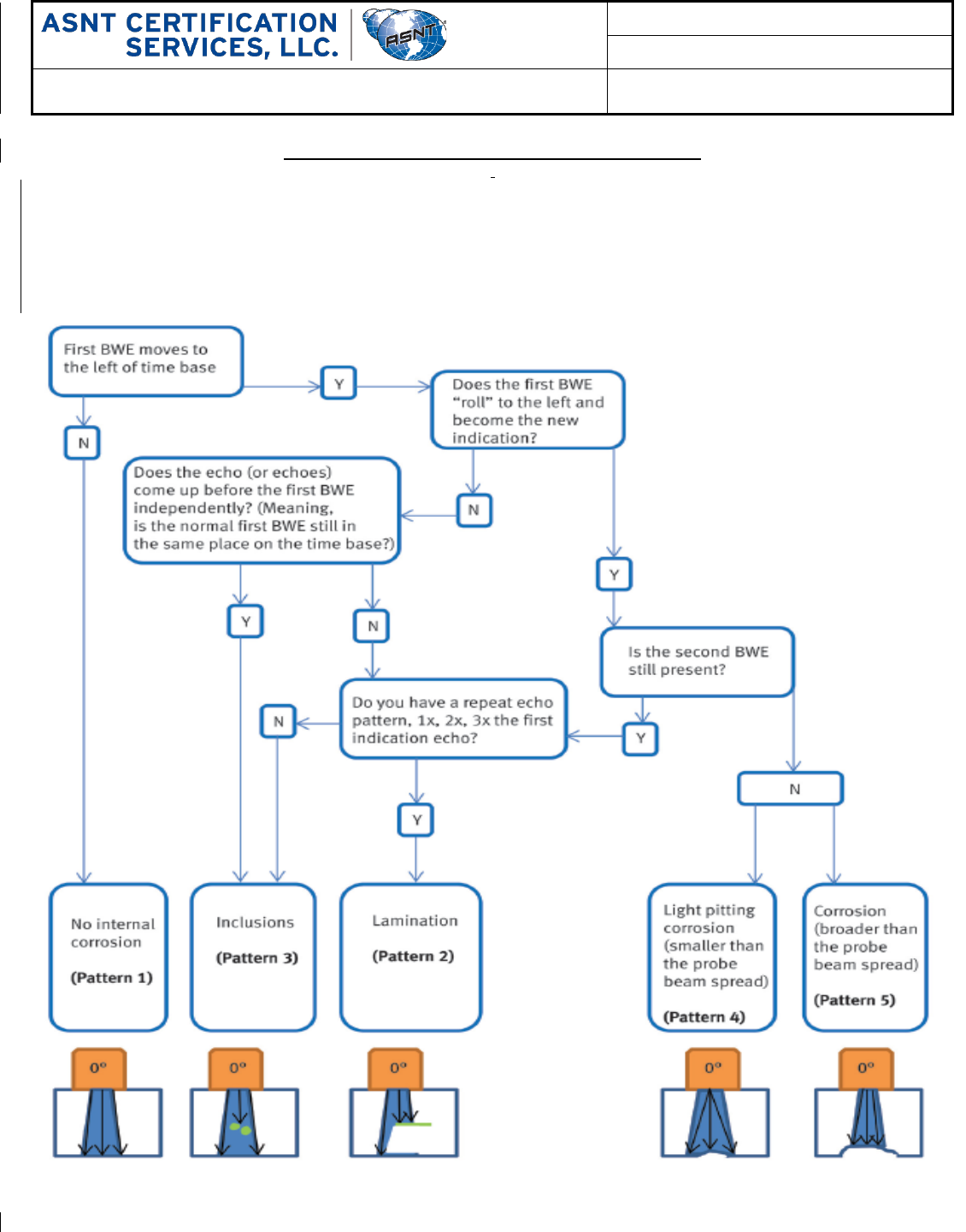
Figure 2 – Evaluation Flowchart (© ASNT 2019)
)
The following figure provides some guidance on signal evaluation in the form of a flowchart that can
be followed for differentiating corrosion from mid-wall laminations or inclusions. This flowchart is
not absolute as every flaw in a material can exhibit different ultrasonic signal behaviors.
Information provided above in sections 1. Laminations and 2. Wall loss should be considered when
determining the nature of ultrasonic signals.
