Fundamentals of Business Process Management

Marlon Dumas
r
Marcello La Rosa
r
Jan Mendling
r
Hajo A. Reijers
Fundamentals of
Business Process
Management
Marlon Dumas
Institute of Computer Science
University of Tartu
Tartu, Estonia
Marcello La Rosa
Queensland University of Technology
and NICTA
Brisbane, Australia
Jan Mendling
Institute for Information Business
Vienna University of Economics
and Business
Vienna, Austria
Hajo A. Reijers
Department of Mathematics
and Computer Science
Eindhoven University of Technology
Eindhoven, The Netherlands
ISBN 978-3-642-33142-8 ISBN 978-3-642-33143-5 (eBook)
DOI 10.1007/978-3-642-33143-5
Springer Heidelberg New York Dordrecht London
Library of Congress Control Number: 2013932467
ACM Computing Classification (1998): J.1, H.4, H.3.5, D.2
© Springer-Verlag Berlin Heidelberg 2013
This work is subject to copyright. All rights are reserved by the Publisher, whether the whole or part of
the material is concerned, specifically the rights of translation, reprinting, reuse of illustrations, recitation,
broadcasting, reproduction on microfilms or in any other physical way, and transmission or information
storage and retrieval, electronic adaptation, computer software, or by similar or dissimilar methodology
now known or hereafter developed. Exempted from this legal reservation are brief excerpts in connection
with reviews or scholarly analysis or material supplied specifically for the purpose of being entered
and executed on a computer system, for exclusive use by the purchaser of the work. Duplication of
this publication or parts thereof is permitted only under the provisions of the Copyright Law of the
Publisher’s location, in its current version, and permission for use must always be obtained from Springer.
Permissions for use may be obtained through RightsLink at the Copyright Clearance Center. Violations
are liable to prosecution under the respective Copyright Law.
The use of general descriptive names, registered names, trademarks, service marks, etc. in this publication
does not imply, even in the absence of a specific statement, that such names are exempt from the relevant
protective laws and regulations and therefore free for general use.
While the advice and information in this book are believed to be true and accurate at the date of pub-
lication, neither the authors nor the editors nor the publisher can accept any legal responsibility for any
errors or omissions that may be made. The publisher makes no warranty, express or implied, with respect
to the material contained herein.
Cover illustration: M.C. Escher’s “Drawing Hands” © 2012 The M.C. Escher Company-Holland. All
rights reserved. www.mcescher.com
Printed on acid-free paper
Springer is part of Springer Science+Business Media (www.springer.com)
To Inga and Maia—Marlon
To Chiara and Lorenzo—Marcello
To Stefanie—Jan
To Maddy, Timon and Mayu—Hajo
Foreword
Business processes represent a core asset of corporations. They have direct impact
on the attractiveness of products and services as perceived by the market. They
determine tasks, jobs and responsibilities and by this, shape the work of every em-
ployee. Processes integrate systems, data, and resources within and across organi-
zations and any failure can bring corporate life to a standstill. Processes determine
the potential of an organization to adapt to new circumstances and to comply with
a fast growing number of legislative requirements. Processes influence the revenue
potential as much as they shape the cost profile of an organization.
However, unlike other corporate assets such as products, services, workforce,
brand, physical or monetary assets, the significance of business processes had not
been appreciated for a long period. Despite the fact that processes are the lifeblood
of an organization, they did not develop the status of a primary citizen in boardroom
discussions and managerial decision-making processes.
Only the growing demands for globalization, integration, standardization, inno-
vation, agility and operational efficiency, and the related challenge of finding further
variables in the corporate ecosystem that can be optimized, have finally increased
the appetite for reflecting on and ultimately improving business processes.
In response, over the last two decades a comprehensive set of tools, techniques,
methods and entire methodologies has been developed providing support for all
stages of the business process lifecycle. Relevant contributions have been made by
diverse disciplines such as Industrial Engineering, Operations Management, Qual-
ity Management, Human Capital Management, corporate governance, conceptual
modeling, workflow management and system engineering.
Business Process Management (BPM) is the discipline that now faces the diffi-
cult, but rewarding task of consolidating and integrating the plethora of these ap-
proaches.
This book is the first and most up-to-date contribution that faces and masters this
challenge. It succinctly captures the current status of BPM and brings meaningful
order and consistency into approaches that often have been developed, discussed
and deployed in isolation.
vii
viii Foreword
“Fundamentals of Business Process Management” derives its merits from its
firm foundation in the latest applied BPM research. Relying on scientifically sound
practices means capitalizing on evidence rather than depending on confidence. This
clearly differentiates this much needed publication from many of its predecessors.
In particular, it gives BPM the credibility that a still young and growing discipline
requires.
The book itself is also a compelling showcase for the importance of a new class of
processes, i.e. long living, internationally distributed, complex and flexible business
processes. In this case, it is the process of jointly writing a book involving four
authors in four different countries. The team has addressed this challenge brilliantly
and the outcome is an impressive compilation of the individual strengths of each
author grounded in a shared understanding of the essential BPM fundamentals and
a common passion for the topic.
I have no doubts that this book will shape the toolset, and hopefully even more
the mindset, of the current and future generations of BPM professionals. This pub-
lication has the potential to become a significant catalyst for future BPM success
by establishing a common sense for the fundamentals of BPM upon which it can
be further developed and tailored to individual circumstances. The book provides
the needed consistency and rigor within and across the diverse and fast growing
community of professionals and researchers committed to and passionate about the
merits of the process-based organization.
Finally, and maybe most of all, the book is an outstanding reference for all stu-
dents who are keen to learn more about and want to embrace the fascination of
BPM. This long missing BPM textbook addresses a severe shortcoming within the
BPM community, i.e. the lack of resources to facilitate the introduction of BPM sub-
jects into tertiary and corporate education. Making BPM more accessible to future
decision makers ensures that processes will play the role they deserve.
Michael RosemannBrisbane, Australia
Preface
First, master the fundamentals.
Larry Bird (1957–)
Business Process Management (BPM) is a special field for more than one reason.
First of all, BPM is a crossroad of multiple, quite different viewpoints. Business
managers are attracted to BPM because of its demonstrated ability to deliver im-
provements in organizational performance, regulatory compliance and service qual-
ity. Industrial engineers see BPM as an opportunity to apply well-trodden manufac-
turing optimization techniques in the context of organizations that deliver services
rather than physical products. Finally, Information Technology (IT) specialists ap-
preciate the fact that BPM provides them with a shared language to communicate
with business stakeholders. Furthermore, business process automation technology
allows IT specialists to implement and monitor IT systems in a way that is aligned
with the vision that business stakeholders have of the organization. In other words,
BPM is a boundary-spanning field that serves as a melting pot for otherwise separate
communities. For those who have experienced how business managers, industrial
engineers and IT professionals often seem to live in different worlds, this shared
field of interest is a remarkable opportunity to achieve a joint understanding of the
inner workings of a business.
A second special characteristic of BPM is that it is both actively practiced and
actively researched. In other words, it is a field where there are both proven and es-
tablished practices as well as open challenges. Businesses around the world are car-
rying out BPM initiatives with the aim to, for example, outperform their competitors
or meet the demands of regulatory authorities. Academics in fields like computer
science, management science, sociology, and engineering are working on the devel-
opment of methods and techniques to support such initiatives. It is appropriate to see
BPM as a “theory in practice” field. On the one hand, practical demands inspire the
development of new methods and technologies. On the other hand, the application
of these methods and technologies in practice feeds back to the drawing boards in
universities and research centers.
After teaching BPM to thousands of students and professionals over the past
decade, we strongly feel the lack of a textbook to give a structure to our courses
and to allow our audience to study for themselves beyond classwork and homework
ix
x Preface
assignments. This situation is not due to a lack of excellent books on BPM—in
fact there is a good number of them—but rather due to the cross-disciplinary and
continuously evolving nature of BPM.
There are excellent treatments of BPM from a business management perspec-
tive, most notably Harmon’s Business Process Change and Sharp and McDermott’s
Workflow Modeling. Both of these books provide useful conceptual frameworks and
practical advice and should definitely lie in the bookshelves (or better in the hands)
of BPM practitioners. However, one needs an introductory background and prefer-
ably years of experience in order to truly appreciate the advice given in these books.
Also, these books give little attention to technology aspects such as business process
management systems and process intelligence tools.
On the other side of the spectrum, other books adopt a computer science per-
spective to BPM, such as Van der Aalst and Van Hee’s Workflow Management and
Weske’s Business Process Management, both focused on process modeling, anal-
ysis and automation for computer scientists. At a more specialized level, one can
find a range of books focusing on process modeling using specific languages—for
example Silver’s BPMN Method and Style.
Against this background, we decided it was time to put together our combined
teaching experience in BPM in order to deliver a textbook that:
• Embraces BPM as a cross-disciplinary field, striking a balance between business
management and IT aspects.
• Covers the entire BPM lifecycle, all the way from identifying processes to ana-
lyzing, redesigning, implementing and monitoring these processes.
• Follows a step-by-step approach punctuated by numerous examples, in order to
make the content accessible to students who have little or no BPM background.
• Contains numerous classroom-tested exercises, both inside each chapter and at
the end of the chapters, so that students can test their skills incrementally and
instructors have material for classwork, homework and projects.
• Relies on a mature and standardized process modeling language, namely BPMN.
In the spirit of a textbook, every chapter contains a number of elaborated exam-
ples and exercises. Some of these exercises are spread throughout the chapter and
are intended to help the reader to incrementally put into action concepts and tech-
niques exposed in the chapter in concrete scenarios. These “in-chapter” exercises
are paired with sample solutions at the end of the chapter. In addition, every chap-
ter closes with a number of further exercises for which no solutions are provided.
Instructors may wish to use these latter exercises for assignments.
Most chapters also contain “highlighted boxes” that provide complementary in-
sights into a specific topic. These boxes are tangential to the flow of the book and
may be skipped by readers who wish to concentrate on the essential concepts. Sim-
ilarly, every chapter closes with a “Further Readings” section that provides external
pointers for readers wishing to deepen their understanding of a specific topic.
To better serve our readership, we have set up a website to collect course mate-
rials: http://fundamentals-of-bpm.org. This website includes slides, lecture record-
ings, sample exams, links to related resources and additional exercises.
Preface xi
The book is designed to support courses of a wide variety. An in-depth course
on BPM could cover all chapters in a balanced way. In order to fit the content into
one semester though, it may be necessary to sacrifice one or two chapters. If this
was required, our suggestion would be to skip Chap. 4 or 10. An introductory BPM
course could skip Chaps. 2, 4, 7 and 10 while still providing a consistent picture
of the field. A course on process automation for IT students could skip Chaps. 2, 5
and 6. A course on process modeling would focus on Chaps. 2 to 5, and possibly
Chap. 9 if the intention is to produce executable process models. Chapters 3 and 4
can be integrated into a broader semester-long course on systems modeling. Finally,
a process improvement course for business students might focus on Chap. 3 and
Chaps. 5 to 8. Naturally, Chap. 1 could find its place in any of the above courses.
Each chapter can be delivered as a combination of lectures and classwork ses-
sions. Shorter chapters (1, 2, 3, 5, 6 and 10) can be delivered in one lecture and one
classwork session. Chapters 4, 8 and 9 may require two lectures and two classwork
sessions each. Chapter 7 can be delivered across two lectures and two classwork
sessions, or it can be delivered in one lecture and one classwork session by skipping
the content on queues and flow analysis.
This textbook is the result of many years of educational practice both at the un-
dergraduate and postgraduate levels in more than half a dozen institutions, including
Eindhoven University of Technology (The Netherlands), Queensland University of
Technology (Australia), Humboldt University of Berlin (Germany), University of
Tartu (Estonia), Vienna University of Economics and Business (Austria) and Na-
tional University of Colombia. The material in this textbook has also served as a
basis for professional training courses delivered to organizations in Australia, The
Netherlands and elsewhere. We are grateful to the thousands of students who over
the past years have given us constructive feedback and encouragement.
We also owe a lot to our many colleagues who encouraged us and provided
us with feedback throughout the entire idea-to-textbook process. We would like to
thank Wil van der Aalst, Raffaele Conforti, Monika Malinova, Johannes Prescher,
Artem Polyvyanyy, Manfred Reichert, Jan Recker, Michael Rosemann, Matthias
Schrepfer, Arthur ter Hofstede, Irene Vanderfeesten, J. Leon Zhao and Michael zur
Muehlen, who all provided constructive feedback on drafts of the book. Fabio Casati
and Boualem Benatallah provided us with initial encouragement to start the writing
process. Special mentions are due to Matthias Weidlich who provided us with de-
tailed and comprehensive suggestions, and Remco Dijkman who shared with us
teaching material that served as input to Chaps. 2 and 9.
Marlon Dumas
Marcello La Rosa
Jan Mendling
Hajo A. Reijers
Tartu, Estonia
Brisbane, Australia
Vienna, Austria
Eindhoven, The Netherlands
Contents
1 Introduction to Business Process Management ............. 1
1.1 ProcessesEverywhere........................ 1
1.2 Ingredients of a Business Process .................. 3
1.3 OriginsandHistoryofBPM..................... 8
1.3.1 The Functional Organization ................ 8
1.3.2 The Birth of Process Thinking ................ 10
1.3.3 TheRiseandFallofBPR .................. 12
1.4 TheBPMLifecycle ......................... 15
1.5 Recap ................................. 26
1.6 SolutionstoExercises........................ 26
1.7 FurtherExercises .......................... 28
1.8 Further Reading ........................... 31
2 Process Identification ........................... 33
2.1 Focusing on Key Processes . . ................... 33
2.1.1 The Designation Phase ................... 34
2.1.2 The Evaluation Phase . ................... 38
2.2 Designing a Process Architecture .................. 42
2.2.1 Identify Case Types . . ................... 44
2.2.2 Identify Functions for Case Types .............. 45
2.2.3 Construct Case/Function Matrices .............. 49
2.2.4 IdentifyProcesses ...................... 50
2.2.5 Complete the Process Architecture ............. 55
2.3 Recap ................................. 57
2.4 SolutionstoExercises........................ 57
2.5 FurtherExercises .......................... 59
2.6 Further Reading ........................... 60
3 Essential Process Modeling ....................... 63
3.1 FirstStepswithBPMN ....................... 63
3.2 Branching and Merging ....................... 67
3.2.1 ExclusiveDecisions..................... 67
xiii
xiv Contents
3.2.2 ParallelExecution...................... 69
3.2.3 InclusiveDecisions ..................... 72
3.2.4 Rework and Repetition ................... 77
3.3 InformationArtifacts ........................ 79
3.4 Resources .............................. 82
3.5 Recap ................................. 89
3.6 SolutionstoExercises........................ 89
3.7 FurtherExercises .......................... 93
3.8 Further Reading ........................... 95
4 Advanced Process Modeling ....................... 97
4.1 Process Decomposition ....................... 97
4.2 Process Reuse ............................100
4.3 More on Rework and Repetition ...................102
4.3.1 Parallel Repetition . . . ...................104
4.3.2 Uncontrolled Repetition ...................107
4.4 HandlingEvents...........................108
4.4.1 MessageEvents .......................108
4.4.2 TemporalEvents.......................110
4.4.3 RacingEvents ........................111
4.5 Handling Exceptions .........................114
4.5.1 Process Abortion .......................115
4.5.2 Internal Exceptions . . ...................116
4.5.3 External Exceptions . . ...................117
4.5.4 Activity Timeouts . . . ...................118
4.5.5 Non-interrupting Events and Complex Exceptions .....119
4.5.6 Interlude: Event Sub-processes ...............121
4.5.7 Activity Compensation ...................122
4.6 ProcessesandBusinessRules....................124
4.7 Process Choreographies .......................125
4.8 Recap .................................129
4.9 SolutionstoExercises........................130
4.10FurtherExercises ..........................146
4.11 Further Reading ...........................152
5 Process Discovery .............................155
5.1 The Setting of Process Discovery ..................155
5.1.1 Process Analyst Versus Domain Expert . . .........156
5.1.2 Three Process Discovery Challenges . . . .........158
5.1.3 Profile of a Process Analyst .................159
5.2 Discovery Methods .........................161
5.2.1 Evidence-Based Discovery .................161
5.2.2 Interview-BasedDiscovery .................162
5.2.3 Workshop-Based Discovery .................164
5.2.4 Strengths and Limitations ..................165
Contents xv
5.3 Process Modeling Method . . . ...................167
5.3.1 Identify the Process Boundaries ...............167
5.3.2 Identify Activities and Events ................167
5.3.3 IdentifyResourcesandTheirHandovers ..........168
5.3.4 IdentifytheControlFlow ..................169
5.3.5 Identify Additional Elements ................169
5.4 Process Model Quality Assurance ..................171
5.4.1 Syntactic Quality and Verification ..............171
5.4.2 Semantic Quality and Validation ..............172
5.4.3 Pragmatic Quality and Certification .............174
5.4.4 ModelingGuidelinesandConventions ...........175
5.5 Recap .................................178
5.6 SolutionstoExercises........................179
5.7 FurtherExercises ..........................181
5.8 Further Reading ...........................183
6 Qualitative Process Analysis .......................185
6.1 Value-Added Analysis ........................185
6.1.1 ValueClassification .....................185
6.1.2 WasteElimination......................189
6.2 RootCauseAnalysis.........................190
6.2.1 Cause–EffectDiagrams ...................191
6.2.2 Why–WhyDiagrams ....................196
6.3 Issue Documentation and Impact Assessment . . . .........198
6.3.1 IssueRegister ........................198
6.3.2 ParetoAnalysisandPICKCharts..............201
6.4 Recap .................................204
6.5 SolutionstoExercises........................205
6.6 FurtherExercises ..........................208
6.7 Further Reading ...........................210
7 Quantitative Process Analysis ......................213
7.1 Performance Measures ........................213
7.1.1 Process Performance Dimensions ..............213
7.1.2 Balanced Scorecard . . ...................217
7.1.3 Reference Models and Industry Benchmarks ........218
7.2 FlowAnalysis ............................219
7.2.1 CalculatingCycleTimeUsingFlowAnalysis........219
7.2.2 CycleTimeEfficiency....................224
7.2.3 Cycle Time and Work-In-Process ..............225
7.2.4 Other Applications and Limitations of Flow Analysis . . . 227
7.3 Queues . . . .............................229
7.3.1 Basics of Queueing Theory .................229
7.3.2 M/M/1 and M/M/c Models .................232
7.3.3 Limitations of Basic Queueing Theory . . .........234
xvi Contents
7.4 Simulation..............................235
7.4.1 Anatomy of a Process Simulation ..............235
7.4.2 Input for Process Simulation ................236
7.4.3 SimulationTools.......................240
7.4.4 AWordofCaution......................243
7.5 Recap .................................243
7.6 SolutionstoExercises........................244
7.7 FurtherExercises ..........................246
7.8 Further Reading ...........................250
8 Process Redesign .............................253
8.1 The Essence of Process Redesign ..................253
8.1.1 Why Redesign? .......................253
8.1.2 What Is Redesign? . . . ...................256
8.1.3 The Devil’s Quadrangle ...................258
8.1.4 How to Redesign? . . . ...................259
8.2 Heuristic Process Redesign . . ...................262
8.2.1 CustomerHeuristics.....................263
8.2.2 Business Process Operation Heuristics . . .........264
8.2.3 Business Process Behavior Heuristics . . . .........266
8.2.4 OrganizationHeuristics ...................267
8.2.5 InformationHeuristics....................270
8.2.6 Technology Heuristics . ...................271
8.2.7 ExternalEnvironmentHeuristics ..............271
8.3 The Case of a Health Care Institution ................273
8.3.1 Sending Medical Files by Post ...............275
8.3.2 PeriodicMeetings ......................275
8.3.3 Requesting Medical Files ..................276
8.4 Product-Based Design ........................278
8.4.1 Analysis: Creating a Product Data Model . .........279
8.4.2 Design: Deriving a Process from a Product Data Model . . 285
8.5 Recap .................................288
8.6 SolutionstoExercises........................289
8.7 FurtherExercises ..........................292
8.8 Further Reading ...........................295
9 Process Automation ...........................297
9.1 AutomatingBusinessProcesses...................297
9.1.1 Business Process Management Systems . . .........298
9.1.2 ArchitectureofaBPMS...................299
9.1.3 TheCaseofACNS .....................304
9.2 Advantages of Introducing a BPMS .................309
9.2.1 Workload Reduction . . ...................309
9.2.2 FlexibleSystemIntegration.................310
9.2.3 ExecutionTransparency...................311
9.2.4 RuleEnforcement ......................312
Contents xvii
9.3 Challenges of Introducing a BPMS .................313
9.3.1 Technical Challenges . ...................313
9.3.2 Organizational Challenges ..................314
9.4 Turning Process Models Executable .................316
9.4.1 Identify the Automation Boundaries . . . .........317
9.4.2 Review Manual Tasks . ...................319
9.4.3 Complete the Process Model ................323
9.4.4 Bring the Process Model to an Adequate Granularity Level 324
9.4.5 Specify Execution Properties ................327
9.4.6 TheLastMile ........................337
9.5 Recap .................................338
9.6 SolutionstoExercises........................338
9.7 FurtherExercises ..........................347
9.8 Further Reading ...........................351
10 Process Intelligence ............................353
10.1 Process Execution and Event Logs .................353
10.1.1 The Perspective of Participants on Process Execution . . . 354
10.1.2 The Perspective of the Process Owner on Process
Execution ..........................354
10.1.3StructureofEventLogs ...................356
10.1.4 Challenges of Extracting Event Logs . . . .........359
10.2 Automatic Process Discovery . ...................360
10.2.1 Assumptions of the α-Algorithm ..............360
10.2.2 The Order Relations of the α-Algorithm ..........361
10.2.3 The α-Algorithm.......................364
10.2.4 Robust Process Discovery ..................366
10.3 Performance Analysis ........................367
10.3.1TimeMeasurement .....................367
10.3.2CostMeasurement......................369
10.3.3 Quality Measurement . ...................370
10.3.4 Flexibility Measurement ...................372
10.4 Conformance Checking .......................373
10.4.1 Conformance of Control Flow ................374
10.4.2 Conformance of Data and Resources . . . .........377
10.5 Recap .................................378
10.6SolutionstoExercises........................379
10.7FurtherExercises ..........................382
10.8 Further Reading ...........................382
References ...................................385
Index ......................................391
Acronyms
6 M Machine, Method, Material, Man, Measurement, Milieu
4 P Policies, Procedures, People, Plant/Equipment
7PMG Seven Process Modeling Guidelines
ABC Activity-Based Costing
APQC American Productivity and Quality Center
ATAMO And Then, A Miracle Occurs
B2B Business-to-Business
BAM Business Activity Monitoring
BOM Bill-of-Material
BPA Business Process Analysis
BPEL Web Service Business Process Execution Language
BPM Business Process Management
BPMN Business Process Model & Notation
BPMS Business Process Management System
BPR Business Process Reengineering
BTO Build-to-Order
BVA Business Value-Adding
CEO Chief Executive Officer
CFO Chief Financial Officer
CIO Chief Information Officer
CMMI Capability Maturity Model Integrated
COO Chief Operations Officer
CPO Chief Process Officer
CRM Customer Relationship Management
CPN Colored Petri Net
CT Cycle Time
DBMS Database Management System
DCOR Design Chain Operations Reference (product design)
DES Discrete-Event Simulation
DMR Department of Main Roads
DMS Document Management System
xix
xx Acronyms
DUR Drug Utilization Review
EPA Environment Protection Agency
EPC Event-driven Process Chain
ERP Enterprise Resource Planning
eTOM Enhanced Telecom Operations Map
FIFO First-In-First-Out
HR Human Resources
IDEF3 Integrated Definition for Process Description Capture Method
ISP Internet Service Provider
IT Information Technology
ITIL Information Technology Infrastructure Library
KM Knowledge Management
KPI Key Performance Indicator
NRW Department of Natural Resources and Water
NVA Non-Value-Adding
OASIS Organization for the Advancement of Structured Information
Standards
OMG Object Management Group
OS Operating System
PCF Process Classification Framework
PD Product Development
PDCA Plan-Do-Check-Act
PO Purchase Order
POS Point-of-Sale
PPM Process Performance Measurement
RBAC Role-based Access Control
RFID Radio-Frequency Identification
RFQ Request for Quote
ROI Return-On-Investment
SCAMPI Standard CMMI Appraisal Method for Process Improvement
SCOR Supply Chain Operations Reference Model
Smart eDA Smart Electronic Development Assessment System
SOA Service-Oriented Architecture
STP Straight-Through-Processing
TCT Theoretical Cycle Time
TOC Theory of Constraints
TQM Total Quality Management
UIMS User Interface Management System
UEL Universal Expression Language
UML Unified Modeling Language
UML AD UML Activity Diagram
VA Value-Adding
VCH Value Creation Hierarchy
VCS Value Creation System
VRM Value Reference Model
Acronyms xxi
WIP Work-In-Progress
WfMC Workflow Management Coalition
WfMS Workflow Management System
WS-BPEL Web Service Business Process Execution Language
WSDL Web Service Definition Language
XES Extensible Event Stream
XML Extensible Markup Language
XSD XML Schema Definition
YAWL Yet Another Workflow Language
List of Figures
Fig. 1.1 Ingredients of a business process ................. 6
Fig. 1.2 How the process moved out of focus through the ages ...... 8
Fig. 1.3 Purchasing process at Ford at the initial stage . . ......... 10
Fig. 1.4 Purchasing process at Ford after redesign ............. 11
Fig. 1.5 Job functions of a manager responsible for a process (a.k.a.
process owner) ........................... 14
Fig. 1.6 Process model for an initial fragment of the equipment rental
process . . ............................. 17
Fig.1.7 BPMlifecycle ........................... 21
Fig. 2.1 The different levels of detail in a process architecture ...... 42
Fig. 2.2 A process architecture for a harbor authority . . ......... 44
Fig. 2.3 Different functional decompositions within the same
organization ............................ 48
Fig.2.4 Acase/functionmatrix....................... 49
Fig. 2.5 A case/function matrix evolving into a process landscape model
(applying Guideline 1) ....................... 50
Fig. 2.6 A case/function matrix evolving into a process landscape model
(applying Guidelines 2–7) . . ................... 54
Fig. 2.7 A case/function matrix evolving into a process landscape model
(applying Guideline 8) ....................... 54
Fig. 2.8 A process map for the mortgage payment process ........ 56
Fig. 3.1 The diagram of a simple order fulfillment process ........ 64
Fig. 3.2 Progress of three instances of the order fulfillment process .... 65
Fig. 3.3 A building (a), its timber miniature (b) and its blueprint (c).
((b): © 2010, Bree Industries; (c): used by permission of
planetclaire.org).......................... 66
Fig.3.4 AnexampleoftheuseofXORgateways............. 68
Fig.3.5 AnexampleoftheuseofANDgateways............. 70
Fig. 3.6 A more elaborated version of the order fulfillment process
diagram .............................. 71
xxiii
xxiv List of Figures
Fig. 3.7 A variant of the order fulfillment process with two different
triggers . . ............................. 72
Fig. 3.8 Modeling an inclusive decision: first trial ............. 73
Fig. 3.9 Modeling an inclusive decision: second trial . . ......... 73
Fig. 3.10 Modeling an inclusive decision with the OR gateway ...... 74
Fig. 3.11 What type should the join gateway have such that instances
of this process can complete correctly? .............. 75
Fig. 3.12 The order fulfillment process diagram with product
manufacturing ........................... 77
Fig. 3.13 A process model for addressing ministerial correspondence . . . 78
Fig.3.14 Theorderfulfillmentexamplewithartifacts ........... 80
Fig.3.15 Theorderfulfillmentexamplewithresourceinformation..... 84
Fig. 3.16 Collaboration diagram between a seller, a customer and two
suppliers.............................. 87
Fig. 4.1 Identifying sub-processes in the order fulfillment process
of Fig. 3.12 ............................ 98
Fig. 4.2 A simplified version of the order fulfillment process after hiding
the content of its sub-processes .................. 99
Fig. 4.3 A process model for disbursing home loans, laid down over
threehierarchicallevelsviatheuseofsub-processes.......100
Fig. 4.4 The process model for disbursing student loans invokes the same
model for signing loans used by the process for disbursing home
loans, via a call activity . . . ...................101
Fig. 4.5 The process model for addressing ministerial correspondence
of Fig. 3.13 simplifiedusingaloopactivity............103
Fig.4.6 Anexampleofunstructuredcycle.................104
Fig. 4.7 Obtaining quotes from five suppliers ...............105
Fig. 4.8 Obtaining quotes from multiple suppliers, whose number is not
knownapriori...........................106
Fig. 4.9 Using a multi-instance pool to represent multiple suppliers . . . 106
Fig. 4.10 Using an ad-hoc sub-process to model uncontrolled repetition . . 108
Fig. 4.11 Replacing activities that only send or receive messages (a)
with message events (b)......................109
Fig. 4.12 Using timer events to drive the various activities of a business
process . . .............................110
Fig. 4.13 A race condition between an incoming message and a timer . . . 112
Fig. 4.14 Matching an internal choice in one party with an event-based
choice in the other party . . . ...................113
Fig. 4.15 An example of deadlocking collaboration between two pools . . 113
Fig. 4.16 Using an event-based gateway to fix the deadlocking
collaboration of Fig. 4.15 .....................114
Fig. 4.17 A collaboration diagram between a client, a travel agency and
anairline..............................115
Fig. 4.18 Using a terminate event to signal improper process termination . 116
Fig. 4.19 Error events model internal exceptions ..............117
List of Figures xxv
Fig. 4.20 Boundary events catch external events that can occur during an
activity...............................118
Fig. 4.21 Non-interrupting boundary events catch external events that
occur during an activity, and trigger a parallel procedure without
interrupting the enclosing activity .................119
Fig. 4.22 Non-interrupting events can be used in combination with signal
events to model complex exception handling scenarios ......120
Fig. 4.23 Event sub-processes can be used in place of boundary events,
and to catch events thrown from outside the scope of a particular
sub-process ............................121
Fig. 4.24 Compensating for the shipment and for the payment .......123
Fig. 4.25 A replenishment order is triggered every time the stock levels
dropbelowathreshold ......................124
Fig. 4.26 The choreography diagram for the collaboration diagram in
Fig. 4.9 ...............................126
Fig. 4.27 The choreography diagram between a seller, a customer and a
carrier ...............................127
Fig. 4.28 Collaboration diagram—part 1/2 (Freight shipment fragment) . . 140
Fig. 4.29 Collaboration diagram—part 2/2 (Merchandise return handling
fragment) .............................141
Fig. 4.30 Choreography diagram—part 1/2.................142
Fig. 4.31 Choreography diagram—part 2/2.................143
Fig. 4.32 Collaboration diagram—part 1/3 (Loan establishment fragment) 144
Fig. 4.33 Collaboration diagram—part 2/3 (Loan disbursement fragment) 145
Fig. 4.34 Collaboration diagram—part 3/3(sub-processes) ........146
Fig. 5.1 The main activities and events of the order fulfillment process . . 168
Fig. 5.2 The activities and events of the order fulfillment process
assigned to pools and lanes . ...................169
Fig. 5.3 The control flow of the order fulfillment process .........170
Fig. 5.4 Quality aspects and quality assurance activities . .........172
Fig. 5.5 Common sound and unsound process fragments .........173
Fig. 5.6 Extract of the order fulfillment process model with bad layout . . 175
Fig. 5.7 Extract of the order fulfillment process model with good layout . 175
Fig. 5.8 A complaint handling process as found in practice ........177
Fig. 5.9 The complaint handling process reworked . . . .........182
Fig. 5.10 A loan application process . . ...................182
Fig. 5.11 A sales campaign process . . ...................183
Fig. 6.1 Template of a cause–effect diagram based on the 6M’s ......194
Fig. 6.2 Cause–effect diagram for issue “Equipment rejected at delivery” 195
Fig.6.3 Templateofawhy–whydiagram .................197
Fig. 6.4 Pareto chart for excessive equipment rental expenditure .....202
Fig. 6.5 PICK chart .............................204
Fig. 6.6 Pareto chart of causal factors of issue “Equipment not available
when needed” ...........................208
Fig. 7.1 Fully sequential process model ..................219
xxvi List of Figures
Fig. 7.2 Process model with XOR-block ..................220
Fig.7.3 XOR-blockpattern ........................220
Fig. 7.4 Process model with AND-block ..................221
Fig. 7.5 AND-block pattern ........................221
Fig. 7.6 Credit application process . . ...................221
Fig.7.7 Exampleofareworkloop.....................222
Fig.7.8 Reworkpattern...........................223
Fig. 7.9 Activity that is reworked at most once ..............223
Fig. 7.10 Credit application process with rework ..............223
Fig. 7.11 Structure of an M/M/1 or M/M/c system, input parameters and
computableparameters ......................233
Fig. 7.12 Histograms produced by simulation of the credit application
process . . .............................239
Fig. 7.13 Cetera’s claim-to-resolution process ...............241
Fig. 7.14 Mortgage process .........................249
Fig. 8.1 The Devil’s Quadrangle . . . ...................259
Fig. 8.2 The intake process .........................274
Fig. 8.3 The intake process after the medical file redesign .........277
Fig. 8.4 The helicopter pilot product data model ..............280
Fig. 8.5 An incorrect process design for the helicopter pilot product data
model . . .............................286
Fig. 8.6 A correct process design for the helicopter pilot product data
model . . .............................286
Fig. 8.7 An alternative process design for the helicopter pilot product
data model .............................287
Fig. 8.8 Solution for the loan proposal ...................291
Fig. 8.9 A complete process design for the helicopter pilot product data
model . . .............................292
Fig. 8.10 A cost-efficient process design for the helicopter pilot product
data model .............................292
Fig.9.1 ThearchitectureofaBPMS....................299
Fig. 9.2 The process modeling tool of Bonita Open Solution from Bonita
Soft ................................300
Fig. 9.3 The worklist handler of Bizagi’s BPM Suite . . .........301
Fig. 9.4 The monitoring tool of Perceptive Software’s BPMOne .....302
Fig. 9.5 The spectrum of BPMS types ...................307
Fig. 9.6 The order fulfillment model that we want to automate ......318
Fig. 9.7 Admission process: the initial (a) and final (c) assessments can
be automated in a BPMS; the assessment by the committee (b)
is a manual process outside the scope of the BPMS ........321
Fig. 9.8 The order fulfillment model of Fig. 9.6, completed with
control-flow and data-flow aspects relevant for automation ....325
Fig. 9.9 The sales process of a B2B service provider . . .........326
Fig.9.10 StructureoftheBPMNformat ..................328
List of Figures xxvii
Fig. 9.11 The XSD describing the purchase order (a) and one of its
instances (b)............................329
Fig. 9.12 The automated prescription fulfillment process . .........342
Fig. 9.13 The model for the sales process of a B2B service provider,
completed with missing control flow and data relevant for
execution..............................345
Fig. 9.14 FixComp’s process model for handling complaints ........348
Fig. 9.15 Claims handling process model ..................349
Fig. 10.1 Example of an event log for the order fulfillment process ....357
Fig. 10.2 Metamodel of the XES format ...................358
Fig.10.3 ExampleofafileintheXESformat................358
Fig. 10.4 Definition of a workflow log . ...................361
Fig. 10.5 Simple control flow patterns . ...................362
Fig. 10.6 Footprint represented as a matrix of the workflow log
L =[a,b,g,h,j,k,i,l, a, c, d, e, f,g, j, h,i,k, l] ......363
Fig. 10.7 Process model constructed by the α-algorithm from workflow
log L =[a, b,g, h, j,k, i, l, a,c,d,e,f, g, j, h, i, k, l] ....365
Fig. 10.8 Examples of two short loops, which are problematic for the
α-algorithm ............................366
Fig. 10.9 Dotted chart of log data . . . ...................368
Fig. 10.10 Timeline chart of log data like PM 232 ..............369
Fig. 10.11 BPMN model with token on start event for replaying the case
a,b,g, i, j,k, l ..........................375
Fig. 10.12 Replaying the non-conforming case a,b,i,j,k,l ........376
Fig. 10.13 Result of replaying cases in the process model . .........377
Fig. 10.14 Process model constructed by the α-algorithm ..........380
Chapter 1
Introduction to Business Process Management
Ab ovo usque ad mala.
Horace (65 BCE–8 BCE)
Business Process Management (BPM) is the art and science of overseeing how work
is performed in an organization to ensure consistent outcomes and to take advantage
of improvement opportunities. In this context, the term “improvement” may take dif-
ferent meanings depending on the objectives of the organization. Typical examples
of improvement objectives include reducing costs, reducing execution times and re-
ducing error rates. Improvement initiatives may be one-off, but also display a more
continuous nature. Importantly, BPM is not about improving the way individual ac-
tivities are performed. Rather, it is about managing entire chains of events, activities
and decisions that ultimately add value to the organization and its customers. These
“chains of events, activities and decisions” are called processes.
In this chapter, we introduce a few essential concepts behind BPM. We will start
with a description of typical processes that are found in contemporary organizations.
Next, we discuss the basic ingredients of a business process and we provide a def-
inition for the concept as well as of BPM. In order to place BPM in a broader per-
spective, we then provide a historical overview of the BPM discipline. Finally, we
discuss how a BPM initiative in an organization typically unfolds. This discussion
leads us to the definition of a BPM lifecycle around which the book is structured.
1.1 Processes Everywhere
Every organization—be it a governmental body, a non-profit organization, or an
enterprise—has to manage a number of processes. Typical examples of processes
that can be found in most organizations include:
• Order-to-cash: This is a type of process performed by a vendor, which starts
when a customer submits an order to purchase a product or a service and ends
when the product or service in question has been delivered to the customer and
the customer has made the corresponding payment. An order-to-cash process en-
compasses activities related to purchase order verification, shipment (in the case
of physical products), delivery, invoicing, payment receipt and acknowledgment.
M. Dumas et al., Fundamentals of Business Process Management,
DOI 10.1007/978-3-642-33143-5_1, © Springer-Verlag Berlin Heidelberg 2013
1
2 1 Introduction to Business Process Management
• Quote-to-order: This type of process typically precedes an order-to-cash process.
It starts from the point when a supplier receives a “Request for Quote” (RFQ)
from a customer and ends when the customer in question places a purchase order
based on the received quote. The order-to-cash process takes the relay from that
point on. The combination of a quote-to-order and the corresponding order-to-
cash process is called a quote-to-cash process.
• Procure-to-pay: This type of process starts when someone in an organization de-
termines that a given product or service needs to be purchased. It ends when
the product or service has been delivered and paid for. A procure-to-pay process
includes activities such as obtaining quotes, approving the purchase, selecting a
supplier, issuing a purchase order, receiving the goods (or consuming the service),
checking and paying the invoice. A procure-to-pay process can be seen as the dual
of quote-to-cash process in the context of business-to-business interactions. For
every procure-to-pay process there is a corresponding quote-to-cash process on
the supplier’s side.
• Issue-to-resolution. This type of process starts when a customer raises a problem
or issue, such as a complaint related to a defect in a product or an issue en-
countered when consuming a service. The process continues until the customer,
the supplier, or preferably both of them, agree that the issue has been resolved.
A variant of this process can be found in insurance companies that have to deal
with “insurance claims”. This variant is often called claim-to-resolution.
• Application-to-approval. This type of process starts when someone applies for a
benefit or privilege and ends when the benefit or privilege in question is either
granted or denied. This type of process is common in government agencies, for
example when a citizen applies for a building permit or when a businessman
applies for a permit to open a business (e.g. a restaurant). Another process that
falls into this category is the admissions process in a university, which starts when
a student applies for admission into a degree. Yet another example is the process
for approval of vacation or special leave requests in a company.
As the above examples illustrate, business processes are what companies do
whenever they deliver a service or a product to customers. The way processes are de-
signed and performed affects both the “quality of service” that customers perceive
and the efficiency with which services are delivered. An organization can outper-
form another organization offering similar kinds of service if it has better processes
and executes them better. This is true not only of customer-facing processes, but
also of internal processes such as the procure-to-pay process, which is performed
for the purpose of fulfilling an internal need.
As we go along this book, we will use a concrete example of a procure-to-pay
process for renting construction equipment, as described below.
Example 1.1 Procure-to-pay process at BuildIT.
BuildIT is a construction company specialized in public works (roads, bridges, pipelines,
tunnels, railroads, etc.). Within BuildIT, it often happens that engineers working at a con-
struction site (called site engineers) need a piece of equipment, such as a truck, an excavator,
1.2 Ingredients of a Business Process 3
a bulldozer, a water pump, etc. BuildIT owns very little equipment and instead it rents most
of its equipment from specialized suppliers.
The existing business process for renting equipment goes as follows. When site engineers
need to rent a piece of equipment, they fill in a form called “Equipment Rental Request”
and send this request by e-mail to one of the clerks at the company’s depot. The clerk at
the depot receives the request and, after consulting the catalogs of the equipment suppliers,
selects the most cost-effective equipment that complies with the request. Next, the clerk
checks the availability of the selected equipment with the supplier via phone or e-mail.
Sometimes the selected option is not available and the clerk has to select an alternative
piece of equipment and check its availability with the corresponding supplier.
Once the clerk has found a suitable piece of equipment available for rental, the clerk adds
the details of the selected equipment to the rental request. Every rental request has to be
approved by a works engineer, who also works at the depot. In some cases, the works
engineer rejects the equipment rental request. Some rejections lead to the cancellation of
the request (no equipment is rented at all). Other rejections are resolved by replacing the
selected equipment with another equipment—such as a cheaper piece of equipment or a
more appropriate piece of equipment for the job. In the latter case, the clerk needs to perform
another availability enquiry.
When a works engineer approves a rental request, the clerk sends a confirmation to the
supplier. This confirmation includes a Purchase Order (PO) for renting the equipment. The
PO is produced by BuildIT’s financial information system using information entered by
the clerk. The clerk also records the engagement of the equipment in a spreadsheet that is
maintained for the purpose of tracking all equipment rentals.
In the meantime, the site engineer may decide that the equipment is no longer needed. In
this case, the engineer asks the clerk to cancel the request for renting the equipment.
In due time, the supplier delivers the rented equipment to the construction site. The site
engineer then inspects the equipment. If everything is in order, the engineer accepts the
engagement and the equipment is put into use. In some cases, the equipment is sent back
because it does not comply with the requirements of the site engineer. In this case, the site
engineer has to start the rental process all over again.
When the rental period expires, the supplier comes to pick up the equipment. Sometimes,
the site engineer asks for an extension of the rental period by contacting the supplier via
e-mail or phone 1–2 days before pick-up. The supplier may accept or reject this request.
A few days after the equipment is picked up, the equipment’s supplier sends an invoice
to the clerk by e-mail. At this point, the clerk asks the site engineer to confirm that the
equipment was indeed rented for the period indicated in the invoice. The clerk also checks
if the rental prices indicated in the invoice are in accordance with those in the PO. After
these checks, the clerk forwards the invoice to the financial department and the finance
department eventually pays the invoice.
1.2 Ingredients of a Business Process
The above example shows that a business process encompasses a number of events
and activities. Events correspond to things that happen atomically, meaning that they
have no duration. The arrival of an equipment at a construction site is an event. This
event may trigger the execution of series of activities. For example, when a piece of
equipment arrives, the site engineer inspects it. This inspection is an activity, in the
sense that it takes time.
When an activity is rather simple and can be seen as one single unit of work, we
call it a task. For example, if the inspection that the site engineer performs is quite
4 1 Introduction to Business Process Management
simple—e.g. just checking that the equipment received corresponds to what was
ordered—we can say that the equipment inspection is a task. If on the other hand
the equipment inspection requires many steps—such as checking that the equipment
fulfills the specification included in the purchase order, checking that the equipment
is in working order, and checking the equipment comes with all the required acces-
sories and safety devices—we will call it an activity.
In addition to events and activities, a typical process involves decision points,
that is, points in time when a decision is made that affects the way the process is
executed. For example, as a result of the inspection, the site engineer may decide
that the equipment should be returned or that the equipment should be accepted.
This decision affects what happens later in the process.
A process also involves a number of actors (human actors, organizations, or soft-
ware systems acting on behalf of human actors or organizations), physical objects
(equipment, materials, products, paper documents) and immaterial objects (elec-
tronic documents and electronic records). For example, the equipment rental pro-
cess involves three types of human actor (clerk, site engineer and works engineer)
and two types of organizational actor (BuildIT and the equipment suppliers). The
process also involves physical objects (the rented equipment), electronic documents
(equipment rental requests, POs, invoices) and electronic records (equipment en-
gagement records maintained in a spreadsheet).
Finally, the execution of a process leads to one or several outcomes. For exam-
ple, the equipment rental process leads to an equipment being used by BuildIT,
as well as a payment being made to the equipment’s supplier. Ideally, an outcome
should deliver value to the actors involved in the process, which in this example are
BuildIT and the supplier. In some cases, this value is not achieved or is only partially
achieved. For example, when an equipment is returned, no value is gained, neither
by BuildIT nor by the supplier. This corresponds to a negative outcome, as opposed
to a positive outcome that delivers value to the actors involved.
Among the actors involved in a process, the one who consumes the output of the
process plays a special role, namely the role of the customer. For example, in the
above process, the customer is the site engineer, since it is the site engineer who
puts the rented equipment to use. It is also the site engineer who will most likely
be dissatisfied if the outcome of the process is unsatisfactory (negative outcome) or
if the execution of the process is delayed. In this example, the customer is internal
to BuildIT, meaning that the customer is an employee of the organization. In other
processes, such as an order-to-cash process, the customer is external to the orga-
nization. Sometimes, there are multiple customers in a process. For example, in a
process for selling a house, there is a buyer, a seller, a real estate agent, one or mul-
tiple mortgage providers, and at least one notary. The outcome of the process is a
sales transaction. This outcome provides value both to the buyer who gets the house
and to the seller who monetizes the house. Therefore, both the buyer and the seller
can be seen as customers in this process, while the remaining actors provide various
services.
Exercise 1.1 Consider the following process for the admission of graduate students
at a university.
1.2 Ingredients of a Business Process 5
In order to apply for admission, students first fill in an online form. Online applications are
recorded in an information system to which all staff members involved in the admissions
process have access to. After a student has submitted the online form, a PDF document is
generated and the student is requested to download it, sign it, and send it by post together
with the required documents, which include:
• Certified copies of previous degree and academic transcripts.
• Results of English language test.
• Curriculum vitae.
When these documents are received by the admissions office, an officer checks the com-
pleteness of the documents. If any document is missing, an e-mail is sent to the student. The
student has to send the missing documents by post. Assuming the application is complete,
the admissions office sends the certified copies of the degrees to an academic recognition
agency, which checks the degrees and gives an assessment of their validity and equivalence
in terms of local education standards. This agency requires that all documents be sent to
it by post, and all documents must be certified copies of the originals. The agency sends
back its assessment to the university by post as well. Assuming the degree verification is
successful, the English language test results are then checked online by an officer at the
admissions office. If the validity of the English language test results cannot be verified, the
application is rejected (such notifications of rejection are sent by e-mail).
Once all documents of a given student have been validated, the admission office forwards
these documents by internal mail to the corresponding academic committee responsible for
deciding whether to offer admission or not. The committee makes its decision based on
the academic transcripts and the CV. The committee meets once every 2 to 3 weeks and
examines all applications that are ready for academic assessment at the time of the meeting.
At the end of the committee meeting, the chair of the committee notifies the admissions
office of the selection outcomes. This notification includes a list of admitted and rejected
candidates. A few days later, the admission office notifies the outcome to each candidate
via e-mail. Additionally, successful candidates are sent a confirmation letter by post.
With respect to the above process, consider the following questions:
1. Who are the actors in this process?
2. Which actors can be considered to be the customer (or customers) in this process?
3. What value does the process deliver to its customer(s)?
4. What are the possible outcomes of this process?
In light of the above, we define a business process as a collection of inter-related
events, activities and decision points that involve a number of actors and objects,
and that collectively lead to an outcome that is of value to at least one customer.
Figure 1.1 depicts the ingredients of this definition and their relations.
Armed with this definition of a business process, we define BPM as a body of
methods, techniques and tools to discover, analyze, redesign, execute and monitor
business processes. This definition reflects the fact that business processes are the
focal point of BPM, and also the fact that BPM involves different phases and activ-
ities in the lifecycle of business processes, as we will discuss later in this chapter.
Other disciplines besides BPM deal with business processes in different ways as
explained in the box “Related Disciplines”. One of the features commonly associ-
ated to BPM is its emphasis on the use of process models throughout the lifecycle
of business processes. Accordingly, process models are present in one way or an-

6 1 Introduction to Business Process Management
Fig. 1.1 Ingredients of a business process
other in virtually all chapters of this book and two chapters are dedicated to process
modeling.
In any case, while it is useful to know that multiple disciplines share the aim of
improving business processes, we should remain pragmatic and not pitch one disci-
pline against the other as if they were competitors. Instead, we should embrace any
technique that helps us to improve business processes, whether or not this technique
is perceived as being part of the BPM discipline (in the strict sense) and regardless
of whether or not the technique in question uses process models.
RELATED DISCIPLINES
BPM is by no means the only discipline that is concerned with improving the
operational performance of organizations. Below, we briefly introduce some
related disciplines and identify key relations and differences between these
disciplines and BPM.
Total Quality Management (TQM) is an approach that both historically
preceded and inspired BPM. The focus of TQM is on continuously improv-
ing and sustaining the quality of products, and by extension also of services.
In this way, it is similar to BPM in its emphasis on the necessity of ongo-
ing improvement efforts. But where TQM puts the emphasis on the products
and services themselves, the view behind BPM is that the quality of prod-
ucts and services can best be achieved by focusing on the improvement of the
processes that create these products and services. It should be admitted that
this view is somewhat controversial, as contemporary TQM adepts would
rather see BPM as one of the various practices that are commonly found
within a TQM program. Not so much a theoretical distinction but an empir-

1.2 Ingredients of a Business Process 7
ical one is that applications of TQM are primarily found in manufacturing
domains—where the products are tangible—while BPM is more oriented to
service organizations.
Operations Management is a field concerned with managing the physical
and technical functions of a firm or organization, particularly those relating
to production and manufacturing. Probability theory, queuing theory, deci-
sion analysis, mathematical modeling, and simulation are all important tech-
niques for optimizing the efficiency of operations from this perspective. As
will be discussed in Chap. 7, such techniques are also useful in the context
of BPM initiatives. What is rather different between operations management
and BPM is that operations management is generally concerned with con-
trolling an existing process without necessarily changing it, while BPM is
often concerned with making changes to an existing process in order to im-
prove it.
Lean is a management discipline that originates from the manufacturing in-
dustry, in particular the engineering philosophy of Toyota. One of the main
principles of Lean is the elimination of waste, i.e. activities that do not add
value to the customer as we will discuss in Chap. 6. The customer orientation
of Lean is similar to that of BPM and many of the principles behind Lean
have been absorbed by BPM. In that sense, BPM can be seen as a more en-
compassing discipline than Lean. Another difference is that BPM puts more
emphasis on the use of information technology as a tool to improve business
processes and to make them more consistent and repeatable.
Six Sigma is another set of practices that originate from manufacturing, in
particular from engineering and production practices at Motorola. The main
characteristic of Six Sigma is its focus on the minimization of defects (er-
rors). Six Sigma places a strong emphasis on measuring the output of pro-
cesses or activities, especially in terms of quality. Six Sigma encourages
managers to systematically compare the effects of improvement initiatives
on the outputs. In practice, Six Sigma is not necessarily applied alone, but
in conjunction with other approaches. In particular, a popular approach is to
blend the philosophy of Lean with the techniques of Six Sigma, leading to
an approach known as Lean Six Sigma. Nowadays, many of the techniques
of Six Sigma are commonly applied in BPM as well. In Chap. 6, we will
introduce a few business process analysis techniques that are shared by Six
Sigma and BPM.
In summary, we can say that BPM inherits from the continuous improve-
ment philosophy of TQM, embraces the principles and techniques of opera-
tions management, Lean and Six Sigma, and combines them with the capa-
bilities offered by modern information technology, in order to optimally align
business processes with the performance objectives of an organization.

8 1 Introduction to Business Process Management
Fig. 1.2 How the process moved out of focus through the ages
1.3 Origins and History of BPM
To better understand why organizations engage in BPM and what benefits it brings
to them, it is worth looking at the reasons why BPM has emerged and evolved
over time. Below we look into the drivers of the BPM discipline from a historical
perspective. We start with the emergence of functional organizations, continue with
the introduction of process thinking, towards the innovations and failures of business
process re-engineering. This discussion provides the basis for the definition of the
BPM lifecycle afterwards.
1.3.1 The Functional Organization
The key idea of BPM is to focus on processes when organizing and managing work
in an organization. This idea may seem intuitive and straightforward at first glance.
Indeed, if one is concerned with the quality of a particular product or service and
the speed of its delivery to a customer, why not consider the very steps that are nec-
essary to produce it? Even though intuitive, it took several evolutionary steps before
this idea became integral part of the work structures of organizations. Figure 1.2
provides an overview of some historical developments relevant to BPM.
In prehistoric times, humans mostly supported themselves or the small groups
they lived in by producing their own food, tools, and other items. In such early
societies, the consumers and producers of a given good were often the same persons.
In industrial terms, people carried out their own production processes. As a result,
they had knowledge of how to produce many different things. In other words, they
were generalists.
In ancient times, in parallel with the rise of cities and city states, this work struc-
ture based on generalists started to evolve towards what can be characterized as an
intermediate level of specialism. People started to specialize in the art of delivering
1.3 Origins and History of BPM 9
one specific type of goods, such as pottery, or providing one particular type of ser-
vices, such as lodging for travelers. This widespread development towards a higher
level of specialism of the workforce culminated in the guilds of the craftsmen dur-
ing the Middle Ages. These guilds were essentially groups of merchants and artisans
concerned with the same economic activity, such as barbers, shoemakers, masons,
surgeons, and sculptors. Workers in this time would have a good understanding of
an entire process that they were involved in, but not so much about the processes
that produced the goods or services they obtained from others.
This higher degree of specialization of the medieval worker shifted further to-
wards a form of pure specialization during the Second Industrial Revolution, be-
tween the second half of the 19th century and the First World War. A name that is
inseparably linked to it is that of Frederick W. Taylor (1856–1915), who proposed
a set of principles known as scientific management. A key element in Taylor’s ap-
proach was an extreme form of labor division. By meticulously studying labor activ-
ities, such as the individual steps that were required to handle pig iron in steel mills,
Taylor developed very specific work instructions for laborers. Laborers would only
be involved with carrying out one of the many steps in the production process. Not
only in industry, but also in administrative settings, such as government organiza-
tions, the concept of division of labor became the most dominant form of organizing
work. The upshot of this development was that workers became pure specialists who
would be concerned with only a single part of one business process.
A side-effect of the ideas of Taylor and his contemporaries was the emergence
of an altogether new class of professionals, that of managers. After all, someone
needed to oversee the productivity of groups of workers concerned with the same
part of a production process. Managers were responsible for pinning down the pro-
ductivity goals for individual workers and making sure that such goals were met.
In contrast to the masters of the medieval guilds, who could only attain such a rank
on the basis of a masterpiece produced by themselves, managers are not necessarily
experts in carrying out the job they oversee. Their main interest is to optimize how
a job is done with the resources under their supervision.
After the emergence of managers, organizations became structured along the
principles of labor division. A next and obvious challenge arose then: How to differ-
entiate between the responsibilities of all these managers? The solution was to create
functional units in which people with a similar focus on part of the production pro-
cess were grouped together. These units were overseen by managers with different
responsibilities. Moreover, the units and their managers were structured hierarchi-
cally: for example, groups are under departments, departments are under business
units, etc. What we see here is the root of the functional units that are familiar to us
today when we think about organizations: purchasing, sales, warehousing, finance,
marketing, human resource management, etc.
The functional organization that emerged from the mindset of the Second In-
dustrial Revolution, dominated the corporate landscape for the greatest part of the
19th and 20th centuries. Towards the end of the 1980s, however, major American
companies such as IBM, Ford, and Bell Atlantic (now Verizon) came to realize that
their emphasis on functional optimization was creating inefficiencies in their op-
erations that were affecting their competitiveness. Costly projects that introduced
10 1 Introduction to Business Process Management
Fig. 1.3 Purchasing process at Ford at the initial stage
new IT systems or reorganized work within a functional department with the aim
of improving its efficiency, were not notably helping these companies to become
more competitive. It seemed as if customers remained oblivious to these efforts and
continued to take their business elsewhere, for example to Japanese competitors.
1.3.2 The Birth of Process Thinking
One of the breakthrough events for the development of BPM was Ford’s acquisi-
tion of a big financial stake in Mazda during the 1980s. When visiting Mazda’s
plants, one of the things that observant Ford executives noticed was that units
within Mazda seemed considerably understaffed in comparison with comparable
units within Ford, yet operated normally. A famous case study illustrating this phe-
nomenon, first narrated by Michael Hammer [26] and subsequently analyzed by
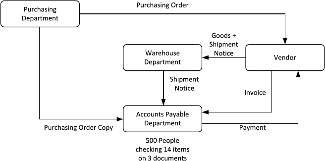
many others, deals with Ford’s purchasing process. Figure 1.3 depicts the way pur-
chasing was done within Ford at the time.
Every purchase that Ford would make needed to go through the purchasing de-
partment. On deciding that a particular quantity of products indeed had to be pur-
chased, this department sent out an order to the vendor in question. It would also
send a copy of that order to accounts payable. When the vendor followed up, the
ordered goods would be delivered at Ford’s receiving warehouse. Along with the
goods came a shipping notice, which was passed on to accounts payable. The ven-
dor would also send out an invoice to accounts payable directly.
Against this background, it becomes clear that the main task of accounts payable
was to check the consistency between three different documents (purchase order
copy, shipping notice, invoice), where each document consists of roughly 14 data
items (type of product, quantity, price, etc.). Not surprisingly, various types of dis-
crepancy were discovered every day and sorting out these discrepancies occupied

1.3 Origins and History of BPM 11
Fig. 1.4 Purchasing process at Ford after redesign
several hundred people within Ford. In contrast, at Mazda only five people worked
at this department, while Mazda was not 100 times smaller than Ford in any rele-
vant measure. Fundamentally, the problem is that Ford was detecting and resolving
with problems (in this case discrepancies) one by one, while Mazda instead was
avoiding the discrepancies in the first place. After a more detailed comparison with
Mazda, Ford carried out several changes in its own purchasing process, leading to
the redesigned process depicted in Fig. 1.4.
First of all, a central database was developed to store information on purchases.
This database was used by the purchasing department to store all the information
on purchase orders. This database replaced one of the original paper streams. Sec-
ondly, new computer terminals were installed at the warehouse department which
gave direct access to that database. When goods arrived, the warehouse personnel
could immediately check whether the delivery actually matched what was originally
purchased. If this was not the case, the goods were simply not accepted: this put the
onus on the vendor to ensure that what was delivered was what was requested and
nothing else. In cases where a match was found between the delivered goods and
the recorded purchase order, the acceptance of the goods was registered. So, the
only thing left to do for accounts payable was to pay what was agreed upon in the
original purchase order. Following this new set-up, Ford managed to bring down
their workforce in accounts payable from roughly 500 people down to 120 people
(a 76 % reduction).
Exercise 1.2 Consider the purchasing process at Ford.
1. Who are the actors in this process?
2. Which actors can be considered to be the customer (or customers) in this process?
3. What value does the process deliver to its customer(s)?
4. What are the possible outcomes of this process?
12 1 Introduction to Business Process Management
A key element in this case study is that a problematic performance issue (i.e. an
excessive amount of time and resources spent on checking documents in accounts
payable) is approached by considering an entire process. In this case, the accounts
payable department plays an important role in the overall purchasing process, but
the process also involves tasks by staff at the purchasing department, the warehouse,
and by the vendor. Regardless of these barriers, changes are made across the process
and these changes are multi-pronged: They include informational changes (informa-
tion exchanges), technological changes (database, terminals), and structural changes
(checks, policies).
This characteristic view on how to look at organizational performance was put
forward in a seminal article by Tom Davenport and James Short [11]. In this article,
the authors urged managers to look at entire processes when trying to improve the
operations of their business, instead of looking at one particular task or business
function. Various cases were discussed where indeed this particular approach proved
to be successful. In the same paper, the important role of IT was emphasized as an
enabler to come up with a redesign of existing business processes. Indeed, when
looking at the Ford–Mazda example it would seem difficult to change the traditional
procedure without the specific qualities of IT, which in general allows access to
information in a way that is independent of time and place.
1.3.3 The Rise and Fall of BPR
The work by Davenport and Short, as well as that of others, triggered the emergence
and widespread adoption of a management concept that was referred to as Business
Process Redesign or Business Process Re-engineering, often conveniently abbre-
viated to BPR. Numerous white papers, articles, and books appeared on the topic
throughout the 1990s and companies all over the world assembled BPR teams to
review and redesign their processes.
The enthusiasm for BPR faded down, however, by the late 1990s. Many compa-
nies terminated their BPR projects and stopped supporting further BPR initiatives.
What had happened? In a retrospective analysis, a number of factors can be distin-
guished:
1. Concept misuse: In some organizations, about every change program or improve-
ment project was labeled BPR even when business processes were not the core of
these projects. During the 1990s, many corporations initiated considerable reduc-
tions of their workforce (downsizing) which, since they were often packaged as
process redesign projects, triggered intense resentment among operational staff
and middle management against BPR. After all, it was not at all clear that oper-
ational improvement was really driving such initiatives.
2. Over-radicalism: Some early proponents of BPR, including Michael Hammer,
emphasized from the very start that redesign had to be radical, in the sense that
a new design for a business process had to overhaul the way the process was
initially organized. A telling indication is one of Michael Hammer’s early papers

1.3 Origins and History of BPM 13
on this subject which bore the subtitle: “Don’t automate, Obliterate”. While a
radical approach may be justified in some situations, it is clear that many other
situations require a much more gradual (incremental) approach.
3. Support immaturity: Even in projects that were process-centered from the start
and took a more gradual approach to improving the business process in question,
people ran into the problem that the necessary tools and technologies to imple-
ment such a new design were not available or sufficiently powerful. One particu-
lar issue centered around the fact that much logic on how processes had to unfold
were hard-coded in the supporting IT applications of the time. Understandably,
people grew frustrated when they noted that their efforts on redesigning a process
were thwarted by a rigid infrastructure.
Subsequently, two key events revived some of the ideas behind BPR and laid
the foundation for the emergence of BPM. First of all, empirical studies appeared
showing that organizations that were process-oriented—that is, organizations that
sought to improve processes as a basis for gaining efficiency and satisfying their
customers—factually did better than non-process-oriented organizations. While the
initial BPR guru’s provided compelling case studies, such as the one on Ford–
Mazda, it remained unclear to many whether these were exceptions rather than the
rule. In one of the first empirical studies on this topic, Kevin McCormack [49]in-
vestigated a sample of 100 US manufacturing organizations and found that process-
oriented organizations showed better overall performance, tended to have a bet-
ter esprit de corps in the workplace, and suffered less from inter-functional con-
flicts. Follow-up studies confirmed this picture, giving renewed credibility to pro-
cess thinking.
A second important development was technological in nature. Different types of
IT system emerged, most notably Enterprise Resource Planning (ERP) systems and
Workflow Management Systems (WfMSs). ERP systems are essentially systems
that store all data related to the business operations of a company in a consistent
manner, so that all stakeholders who need access to these data can gain such access.
This idea of a single shared and centralized database enables the optimization of
information usage and information exchanges, which is a key enabler of process
improvement (cf. Chap. 8).
1
WfMSs on the other hand are systems that distribute
work to various actors in a company on the basis of process models. By doing so,
a WfMS make it easier to implement changes to business processes (e.g. to change
the order in which steps are performed) because the changes made in the process
model can be put into execution with relative ease, compared to the situation where
the rules for executing the process are hard-coded inside complex software systems
and buried inside tens of thousands of lines of code. Also, a WfMS very closely
supports the idea of working in a process-centered manner.
1
In reality, ERP systems are much more than a shared database. They also incorporate numerous
modules to support typical functions of an organization such as accounting, inventory management,
production planning, logistics, etc. However, from the perspective of process improvement, the
shared database concept behind ERP systems is a major enabler.

14 1 Introduction to Business Process Management
Fig. 1.5 Job functions of a manager responsible for a process (a.k.a. process owner)
Originally, WfMSs were concerned mainly with routing work between human
actors. Later on, these systems were little by little extended with modules to monitor
and analyze the execution of business processes. In parallel, the emergence of Web
services made it easier to connect a WfMS with other systems, in particular ERP
systems. As WfMSs became more sophisticated and better integrated with other
enterprise systems, they became known as Business Process Management Systems
(BPMSs). The functionality of BPMSs and their role in the automation of business
processes will be discussed in Chap. 9.
The above historical view suggests that BPM is a revival of BPR, as indeed BPM
adopts the process-centered view on organizations. Some caution is due though
when BPR and BPM are being equated. The relation is much better understood
on the basis of Fig. 1.5.
This figure shows that a manager that is responsible for a business process—also
called the process owner—is concerned with planning and organizing the process on
the one hand and monitoring the process on the other. The figure allows us to explain
the differences in scope between BPR and BPM. While both approaches take the
business process as a starting point, BPR is primarily concerned with planning and
organizing the process. By contrast, BPM provides concepts, methods, techniques,
and tools that cover all aspects of managing a process—plan, organize, monitor,
control–as well as its actual execution. In other words, BPR should be seen as a
subset of techniques that can be used in the context of BPM.
This discussion highlights that BPM encompasses the entire lifecycle of busi-
ness processes. Accordingly, the next section provides an overview of the concepts,
methods, techniques, and tools that compose the BPM discipline through the lens of
the BPM lifecycle. This lens provides a structured view of how a given process can
be managed.
1.4 The BPM Lifecycle 15
1.4 The BPM Lifecycle
In general, the first question that a team embarking on a BPM initiative needs to
clarify is “what business processes are we intending to improve”? Right at the outset
and before the possibility of applying BPM is put on the table, there will probably
already be an idea of what operational problems the team has to address and what
business processes are posing those operational problems. In other words, the team
will not start from scratch. For example, if the problem is that site engineers com-
plain that their job is being hampered by difficulties in securing construction equip-
ment when needed, and knowing that this equipment is to a large extent rented, it
is clear that this problem should be addressed by looking at the equipment rental
process. Still, one has to delimit this process. In particular, one has to answer ques-
tions such as: Does the process start right from the moment when rental suppliers
are selected? Does it end when the rented equipment is delivered to the construction
site or does it end when the equipment is returned back to the supplier, or does it
continue until the fee for equipment rental has been paid to the supplier?
These questions might be easy or hard to answer depending on how much pro-
cess thinking has taken place in the organization beforehand. If the organization has
engaged in BPM initiatives before, it is likely that an inventory of business pro-
cesses is available and that the scope of these processes has been defined, at least to
some extent. In organizations that have not engaged in BPM before, the BPM team
has to start by at least identifying the processes that are relevant to the problem on
the table, delimiting the scope of these processes, and identifying relations between
these processes, such as for example part-of relations (i.e. one process being part of
another process). This initial phase of a BPM initiative is termed process identifi-
cation. This phase leads to a so-called process architecture, which typically takes
the form of a collection of processes and links between these processes representing
different types of relation.
In general, the purpose of engaging in a BPM initiative is to ensure that the busi-
ness processes covered by the BPM initiative lead to consistently positive outcomes
and deliver maximum value to the organization in servicing its clients. Measuring
the value delivered by a process is a crucial step in BPM. As renowned software en-
gineer, Tom DeMarco, once famously put it: “You can’t control what you can’t mea-
sure”. So before starting to analyze any process in detail, it is important to clearly
define the process performance measures (also called process performance metrics)
that will be used to determine whether a process is in “good shape” or in “bad
shape”.
Cost-related measures are a recurrent class of measures in the context of BPM.
For example, coming back to the equipment rental process, a possible performance
measure is the total cost of all equipment rented by BuildIT per time interval (e.g.
per month). Another broad and recurrent class of measures are those related to time.
An example is the average amount of time elapsed between the moment an equip-
ment rental request is submitted by a site engineer and the delivery of the equipment
to the construction site. This measure is generally called cycle time. Finally, a third
class of recurrent measures are those related to quality, and specifically error rates.
16 1 Introduction to Business Process Management
Error rate is the percentage of times that an execution of the process ends up in a
negative outcome. In the case of the equipment rental process, one such measure
is the number of pieces of equipment returned because they are unsuitable, or due
to defects in the delivered equipment. The identification of such performance mea-
sures (and associated performance objectives) is crucial in any BPM initiative. This
identification is generally seen as part of the process identification phase, although
in some cases it may be postponed until later phases.
Exercise 1.3 Consider the student admission process described in Exercise 1.1.
Taking the perspective of the customer, identify at least two performance measures
that can be attached to this process.
Once a BPM team has identified which processes they are dealing with and which
performance measures should be used, the next phase for the team is to understand
the business process in detail. We call this phase process discovery. Typically, one of
the outcomes of this phase is one or several as-is process models. These as-is pro-
cess models should reflect the understanding that people in the organization have
about how work is done. Process models are meant to facilitate communication be-
tween stakeholders involved in a BPM initiative. Therefore, they have to be easy
to understand. In principle, we could model a business process by means of tex-
tual descriptions, like the textual description in Example 1.1. However, such textual
descriptions are cumbersome to read and easy to misinterpret because of the ambi-
guity inherent in free-form text. This is why it is common practice to use diagrams
in order to model business processes. Diagrams allow us to more easily comprehend
the process. Also, if the diagram is made using a notation that is understood by all
stakeholders, there is less room for any misunderstanding. Note that these diagrams
may still be complemented with textual descriptions in fact it is common to see
analysts documenting a process using a combination of diagrams and text.
There are many languages for modeling business processes diagrammatically.
Perhaps one of the oldest ones are flowcharts. In their most basic form, flowcharts
consist of rectangles, representing activities, and diamonds, representing points in
the process where a decision is made. More generally, we can say that regardless of
the specific notation used, a diagrammatic process model typically consists of two
types of node: activity nodes and control nodes. Activity nodes describe units of
work that may be performed by humans or software applications, or a combination
thereof. Control nodes capture the flow of execution between activities. Although
not all process modeling languages support it, a third important type of element
in process models are event nodes. An event node tells us that something may or
must happen, within the process or in the environment of the process, that requires a
reaction, like for example the arrival of a message from a customer asking to cancel
their purchase order. Other types of node may appear in a process model, but we can
say that activity nodes, event nodes and control nodes are the most basic ones.
Several extensions of flowcharts exist, like cross-organizational flowcharts,
where the flowchart is divided into so-called swimlanes that denote different organi-
zational units (e.g. different departments in a company). If you are familiar with the

1.4 The BPM Lifecycle 17
Fig. 1.6 Process model for an initial fragment of the equipment rental process
Unified Modeling Language (UML), you probably will have come across UML Ac-
tivity Diagrams. At their core, UML Activity Diagrams are cross-organizational
flowcharts. However, UML Activity Diagrams go beyond cross-organizational
flowcharts by providing symbols to capture data objects, signals and parallelism
among other aspects. Yet another language for process modeling are Event-driven
Process Chains (EPCs). EPCs have some similarities with flowcharts but they differ
from flowcharts in that they treat events as first-class citizens. Other languages used
for process modeling include data-flow diagrams and IDEF3, just to name two.
It would be mind-boggling to try to learn all these languages at once. Fortunately,
nowadays there is a widely used standard for process modeling, namely the Business
Process Model and Notation (BPMN). The latest version of BPMN is BPMN 2.0.
It was released as a standard by the Object Management Group (OMG) in 2011.
In BPMN, activities are represented as rounded rectangles. Control nodes (called
gateways) are represented using diamond shapes. Activities and control nodes are
connected by means of arcs (called flows) that determine the order in which the pro-
cess is executed. Figure 1.6 provides a model representing an initial fragment of the
equipment rental process, up to the point where the works engineer accepts or rejects
the equipment rental request. This process model shows two decision points. In the
first one, the process takes one of two paths depending on whether the equipment
is available or not. In the second, the equipment rental request is either approved or
rejected. The model also shows the process participants involved in this fragment
of the process, namely the site engineer, the clerk and the works engineer. Each of
these participants is shown as a separate lane containing the activities performed by
the participant in question.
18 1 Introduction to Business Process Management
The process model in Fig. 1.6 is captured at a high level of abstraction. At best, it
can serve to give to an external person a summary of what happens in this process.
In some cases, however, the model needs more details for it to be useful. Which
additional details should be included in a process model depends on the purpose.
Oftentimes, process models are intended to serve as documentation of the way
an organization works. In this case, the key characteristics of process models are
simplicity and understandability. Accordingly, additional text annotations might be
added to the process model to clarify the meaning of certain activities or events, but
beyond such annotations, not much additional detail would be added. In other cases,
process models are intended to be analyzed in detail, for example in order to mea-
sure process performance. In this case, further details may be required such as how
much time each task takes (on average). Finally, in a few cases, process models are
intended to be deployed into a BPMS for the purpose of coordinating the execution
of the process (cf. Sect. 1.3.3). In the latter case, the model needs to be extended
with a significant amount of details regarding the inputs and outputs of the process
and each its activities.
Having understood the as-is process in detail, the next step is to identify and
analyze the issues in this process. One potential issue in BuildIT’s equipment rental
process is that the cycle time is too high. As a result, site engineers do not manage to
get the required equipment on time. This may cause delays in various construction
tasks, which may ripple down into delays in the construction projects. In order to
analyze these issues, an analyst would need to collect information about the time
spent in each task of the process, including both the amount of time that process
participants spend actually doing work and the amount of idle time, meaning the
amount of time when the equipment request is blocked, waiting for something to
happen. This idle time is also called waiting time. Also, the analyst would need to
gather information regarding the amount of rework that takes place in the process.
Here, rework means that one or several tasks are repeated because something went
wrong. For example, when the clerk identifies a suitable piece of equipment in a
supplier’s catalog, but later finds out that the piece of equipment is not available
on the required dates, the clerk might need to search again for an alternative piece
of equipment from another supplier. Valuable time is spent by the clerk going back
and forth between consulting the catalogs and contacting the suppliers to check the
availability of plants. In order to analyze this issue, the analyst would need to find
out in what percentage of cases the availability check fails and thus how often the
clerk needs to do some rework in order to identify alternative pieces of equipment
and check for their availability. Given this information, a process analyst can employ
various techniques to be discussed throughout this book, in order to trace down the
cause(s) of long cycle times and to identify ways of changing the process in order
to reduce the cycle time.
Another potential issue in BuildIT’s equipment rental process is that sometimes
the equipment delivered at the construction site is unsuitable, and the site engineer
has to reject it. This is an example of a negative outcome. To analyze this issue,
an analyst would need to find out how often such negative outcomes are occurring.
Secondly, the analysts would need to obtain information that would allow them
to understand why such negative outcomes are happening. In other words, where
1.4 The BPM Lifecycle 19
did things go wrong in the first place? Sometimes, this negative outcome might
stem from miscommunication, for example between the site engineer and the clerk.
Otherwise it might come from inaccurate data (e.g. errors in the description of the
equipment) or from an error on the supplier’s side. Only by identifying, classifying
and ultimately understanding the main causes of such negative outcomes can an
analyst find out what would be the most suitable way of addressing this issue. The
identification and assessment of issues and opportunities for process improvement
is hereby called the process analysis phase.
We observe that the two issues discussed above are tightly related to performance
measures. For example, the first issue above is tied to cycle time and waiting time,
both of which are typical performance measures of a process. Similarly, the second
issue is tied to the “percentage of equipment rejections”, which is essentially an error
rate—another typical performance measure. Thus, assessing the issues of a process
often goes hand-in-hand with measuring the current state of the process with respect
to certain performance measures.
Exercise 1.4 Consider again the student admission process described in Exer-
cise 1.1. Taking the perspective of the customer, think of at least two issues that
this process might have.
Once issues in a process have been analyzed and possibly quantified, the next
phase is to identify and analyze potential remedies for these issues. At this point, the
analyst will consider multiple possible options for addressing a problem. In doing
so, the analyst needs to keep in mind that a change in a process to address one
issue may potentially cause other issues down the road. For example, in order to
speed-up the equipment rental process, one might think of removing the approval
steps involving the works engineer. If pushed to the extreme, however, this change
would mean that the rented equipment might sometimes not be optimal since the
works engineer viewpoint is not taken into account. The works engineer has a global
view on the construction projects and may be able to propose alternative ways of
addressing the equipment needs of a construction project in a more effective manner.
Changing a process is not as easy as it sounds. People are used to work in a cer-
tain way and might resist changes. Furthermore, if the change implies modifying the
information system(s) underpinning the process, the change may be costly or may
require changes not only in the organization that coordinates the process, but also in
other organizations. For example, one way to eliminate the rework that the clerk has
to do when checking for availability of equipment, would be that the suppliers pro-
vide information regarding the availability of plants. This way, the clerk would use
the same interface to search for suitable equipment and to check the availability of
the equipment for the required period of time. However, this change in the process
would require that the suppliers change their information system, so that their sys-
tem exposes up-to-date equipment availability information to BuildIT. This change
is at least partially outside the control of BuildIT. Assuming that suppliers would
be able to make such changes, a more radical solution that could be considered
would be to provide mobile devices and Internet connection to the site engineers, so
20 1 Introduction to Business Process Management
that they can consult the catalog of equipment (including availability information)
anytime and anywhere. This way, the clerk would not need to be involved in the
process during the equipment search phase, therefore avoiding miscommunications
between the site engineer and the clerk. Whether or not this more radical change is
viable would require an in-depth analysis of the cost of changing the process in this
way versus the benefits that such change would provide.
Exercise 1.5 Given the issues in the admissions process identified in Exercise 1.4,
what possible changes do you think could be made to this process in order to address
these issues?
Equipped with an understanding of one or several issues in a process and a can-
didate set of potential remedies, analysts can propose a redesigned version of the
process, in other words a to-be process which would address the issues identified
in the as-is process. This to-be process is the main output of the process redesign
phase. Here, it is important to keep in mind that analysis and redesign are intricately
related. There may be multiple redesign options and each of these options needs to
be analyzed, so that an informed choice can be made as to which option should be
chosen.
Once redesigned, the necessary changes in the ways of working and the IT sys-
tems of the organization should be implemented so that the to-be process can even-
tually be put into execution. This phase is called process implementation.Inthe
case of the equipment rental process, the process implementation phase would mean
putting in place an information system to record and to track equipment rental re-
quests, POs associated to approved requests and invoices associated to these POs.
Deploying such an information system means not only developing the IT compo-
nents of this system. It would also relate to training the process participants so that
they perform their work in the spirit of the redesigned process and make the best use
of the IT components of the system.
More generally, process implementation may involve two complementary facets:
organizational change management and process automation. Organizational change
management refers to the set of activities required to change the way of working of
all participants involved in the process. These activities include:
• Explaining the changes to the process participants to the point that they under-
stand both what changes are being introduced and why these changes are benefi-
cial to the company.
• Putting in place a change management plan so that stakeholders know when will
the changes be put into effect and what transitional arrangements will be em-
ployed to address problems during the transition to the to-be process.
• Training users to the new way of working and monitoring the changes in order to
ensure a smooth transition to the to-be process.
On the other hand, process automation involves the configuration or implementa-
tion of an IT system (or the re-configuration of an existing IT system) to support the
“to-be” process. This system should support process participants in the performance

1.4 The BPM Lifecycle 21
Fig. 1.7 BPM lifecycle
of the tasks of the process. This may include assigning tasks to process participants,
helping process participants to prioritize their work, providing process participants
with the information they need to perform a task, and performing automated cross-
checks and other automated tasks where possible. There are several ways to im-
plement such an IT system. This book focuses on one particular approach, which
consists of extending the to-be process model obtained from the process redesign
phase in order to make it executable by a BPMS (cf. Sect. 1.3.3).
Over time, some adjustments might be required because the implemented busi-
ness process does not meet expectations. To this end, the process needs to be moni-
tored and analysts ought to scrutinize the data collected by monitoring the process in
order to identify needed adjustments to better control the execution of the process.
These activities are encompassed by the process monitoring and controlling phase.
This phase is important because addressing one or a handful of issues in a process
is not the end of the story. Instead, managing a process requires a continuous effort.
Lack of continuous monitoring and improvement of a process leads to degradation.
As Michael Hammer once put it: “every good process eventually becomes a bad pro-
cess”, unless continuously adapted and improved to keep up with the ever-changing
landscape of customer needs, technology and competition. This is why the phases
in the BPM lifecycle should be seen as being circular: the output of monitoring and
controlling feeds back into the discovery, analysis and redesign phases.
To sum up, we can view BPM as continuous cycle comprising the following
phases (see Fig. 1.7):
• Process identification. In this phase, a business problem is posed, processes rele-
vant to the problem being addressed are identified, delimited and related to each
other. The outcome of process identification is a new or updated process archi-
tecture that provides an overall view of the processes in an organization and their
relationships. In some cases, process identification is done in parallel with per-

22 1 Introduction to Business Process Management
formance measure identification. In this book, however, we will associate perfor-
mance measure identification with the process analysis phase, given that perfor-
mance measures are often used for process analysis.
• Process discovery (also called as-is process modeling). Here, the current state
of each of the relevant processes is documented, typically in the form of one or
several as-is process models.
2
• Process analysis. In this phase, issues associated to the as-is process are identi-
fied, documented and whenever possible quantified using performance measures.
The output of this phase is a structured collection of issues. These issues are typ-
ically prioritized in terms of their impact, and sometimes also in terms of the
estimated effort required to resolve them.
• Process redesign (also called process improvement). The goal of this phase is to
identify changes to the process that would help to address the issues identified
in the previous phase and allow the organization to meet its performance objec-
tives. To this end, multiple change options are analyzed and compared in terms of
the chosen performance measures. This entails that process redesign and process
analysis go hand-in-hand: As new change options are proposed, they are ana-
lyzed using process analysis techniques. Eventually, the most promising change
options are combined, leading to a redesigned process. The output of this phase
is typically a to-be process model, which serves as a basis for the next phase.
• Process implementation. In this phase, the changes required to move from the
as-is process to the to-be process are prepared and performed. Process imple-
mentation covers two aspects: organizational change management and process
automation. Organizational change management refers to the set of activities re-
quired to change the way of working of all participants involved in the process.
Process automation on the other hand refers to the development and deployment
of IT systems (or enhanced versions of existing IT systems) that support the to-be
process. In this book, our focus with respect to process implementation is on pro-
cess automation, as organizational change management is an altogether separate
field. More specifically, the book presents one approach to process automation
wherein an executable process model is derived from the to-be process model
and this executable model is deployed in a BPMS.
• Process monitoring and controlling. Once the redesigned process is running, rel-
evant data are collected and analyzed to determine how well is the process per-
forming with respect to its performance measures and performance objectives.
Bottlenecks, recurrent errors or deviations with respect to the intended behavior
are identified and corrective actions are undertaken. New issues may then arise, in
the same or in other processes, requiring the cycle to be repeated on a continuous
basis.
2
This phase is also called process design in the literature. However, process discovery is arguably a
more appropriate term since the process already exists, at least implicitly in the heads of the actors
who perform it. The goal of this phase is generally to discover the process rather than to design it.
In rare cases (e.g. new companies) no process is yet in place so the discovery and analysis phases
are not required and the process has to be designed for the first time rather than redesigned.

1.4 The BPM Lifecycle 23
The BPM lifecycle helps to understand the role of technology in BPM. Tech-
nology in general, and especially Information Technology (IT), is a key instrument
to improve business processes. Not surprisingly, IT specialists such as system engi-
neers often play a significant role in BPM initiatives. However, to achieve maximum
efficacy, system engineers need to be aware that technology is just one instrument
for managing and executing processes. System engineers need to work together with
process analysts in order to understand what the main issues affecting a given pro-
cess, and how to best address these issues, be it by means of automation or by other
means. As a renowned technology businessman, Bill Gates, once famously put it:
“The first rule in any technology used in a business is that automation applied to
an efficient operation will magnify the efficiency. The second is that automation
applied to an inefficient operation will magnify the inefficiency”. This means that
learning how to design and improve processes—and not only how to build an IT
system to automate a narrow part of a business process—is a fundamental skill that
should be in the hands of any IT graduate. Reciprocally, business graduates need
to understand how technology, and particularly IT, can be used to optimize the ex-
ecution of business processes. This book aims at bridging these two viewpoints by
presenting an integrated viewpoint covering the whole BPM lifecycle.
A complementary viewpoint on the BPM lifecycle is given by the box “Stake-
holders in the BPM lifecycle”. This box summarizes the roles in a company that
are directly or indirectly involved in BPM initiatives.
3
The list of roles described in
the box highlights the fact that BPM is inter-disciplinary. A typical BPM initiative
involves managers at different levels in the organization, administrative and field
workers (called process participants in the box), business and system analysts and
IT teams. Accordingly, the book aims at giving a balanced view of techniques both
from management science and IT, as they pertain to BPM.
STAKEHOLDERS IN THE BPM LIFECYCLE
There are different stakeholders involved with a business process throughout
its lifecycle. Among them we can distinguish the following individuals and
groups.
• Management Team. Depending on how the management of a company is
organized, one might find the following positions. The Chief Executive Of-
ficer (CEO) is responsible for the overall business success of the company.
The Chief Operations Officer (COO) is responsible for defining the way
operations are set-up. In some companies, the COO is also responsible for
process performance, while in other companies, there is a dedicated posi-
3
The role of the customer is not listed in the box as this role is already discussed in previous
sections.

24 1 Introduction to Business Process Management
tion of Chief Process Officer (CPO) for this purpose. The Chief Information
Officer (CIO) is responsible for the efficient and effective operation of the
information system infrastructure. In some organizations, process redesign
projects are driven by the CIO. The Chief Financial Officer (CFO)isre-
sponsible for the overall financial performance of the company. The CFO
may also be responsible for certain business processes, particularly those
that have a direct impact on financial performance. Other management po-
sitions that have a stake in the lifecycle of processes include the Human
Resources (HR) director. The HR director and their team play a key role in
processes that involve significant numbers of process participants. In any
case, the management team is responsible for overseeing all processes, ini-
tiating process redesign initiatives, and providing resources and strategic
guidance to stakeholders involved in all phases of the business process life-
cycle.
• Process Owners. A process owner is responsible for the efficient and effec-
tive operation of a given process. As discussed in the context of Fig. 1.5,
a process owner is responsible on the one hand for planning and organizing,
and on the other hand for monitoring and controlling the process. In their
planning and organizing role, the process owner is responsible for defining
performance measures and objectives as well as initiating and leading im-
provement projects related to their process. They are also responsible for
securing resources so that the process runs smoothly on a daily basis. In
their monitoring and controlling role, process owners are responsible for
ensuring that the performance objectives of the process are met and taking
corrective actions in case they are not met. Process owners also provide
guidance to process participants on how to resolve exceptions and errors
that occur during the execution of the process. Thus, the process owner is
involved in process modeling, analysis, redesign, implementation and mon-
itoring. Note that the same individual could well be responsible for multi-
ple processes. For example, in a small company, a single manager might
be responsible both for the company’s order-to-cash process and for the
after-sales customer service process.
• Process Participants. Process participants are human actors who perform
the activities of a business process on a day-to-day basis. They conduct
routine work according to the standards and guidelines of the company.
Process participants are coordinated by the process owner, who is respon-
sible to deal with non-routine aspects of the process. Process participants
are also involved as domain experts during process discovery and process
analysis. They support redesign activities and implementation efforts.
• Process Analysts. Process analysts conduct process identification, discov-
ery (in particular modeling), analysis and redesign activities. They coor-
dinate process implementation as well as process monitoring and control-
ling. They report to management and process owners and closely interact

1.4 The BPM Lifecycle 25
with process participants. Process analyst typically have one of two back-
grounds. Process analysts concerned with organizational requirements, per-
formance, and change management have a business background. Mean-
while, process analysts concerned with process automation have an IT
background.
• System Engineers. System engineers are involved in process redesign and
implementation. They interact with process analysts to capture system re-
quirements. They translate requirements into a system design and they are
responsible for the implementation, testing and deployment of this system.
System engineers also liaise with the process owner and process partici-
pants to ensure that the developed system supports their work in an effec-
tive manner. Oftentimes, system implementation, testing and deployment
are outsourced to external providers, in which case the system engineering
team will at least partially consist of contractors.
• The BPM Group (also called BPM Centre of Excellence). Large organiza-
tions that have been engaged in BPM for several years would normally have
accumulated valuable knowledge on how to plan and execute BPM projects
as well as substantial amounts of process documentation. The BPM Group
is responsible for preserving this knowledge and documentation and ensur-
ing that they are used to meet the organization’s strategic goals. Specifi-
cally, the BPM group is responsible for maintaining the process architec-
ture, prioritizing process redesign projects, giving support to the process
owners and process analysts, and ensuring that the process documentation
is maintained in a consistent manner and that the process monitoring sys-
tems are working effectively. In other words, the BPM group is responsible
for maintaining a BPM culture and ensuring that this BPM culture is sup-
porting the strategic goals of the organization. Not all organizations have a
dedicated BPM Group. BPM Groups are most common in large organiza-
tions with years of BPM experience.
In the rest of the book, we will dive consecutively into each of the phases of the
BPM lifecycle. Chapter 2 deals with the process identification phase. Chapters 3–4
provide an introduction to process modeling, which serves as background for sub-
sequent phases in the BPM lifecycle. Chapter 5 deals with the process discovery
phase. Chapters 6–7 present a number of process analysis techniques. We classify
these techniques into qualitative (Chap. 6) and quantitative (Chap. 7) ones. A quan-
titative technique is one that takes raw data or measurements as input (e.g. perfor-
mance measures at the level of tasks) and produces aggregated measurements and
quantitative summaries as output. On the other hand, a qualitative technique involves
human judgment, for example in order to classify tasks or issues according to sub-
jective criteria. Note that qualitative techniques may involve quantitative assessment
in addition to human judgment, as these two sources of insights often serve comple-
mentary purposes. Next, Chap. 8 gives an overview of process redesign techniques,
26 1 Introduction to Business Process Management
while Chap. 9 discusses process implementation with a focus on automation aspects.
Finally, Chap. 10 introduces process intelligence tools and techniques, which form
the backbone of modern process monitoring practices.
1.5 Recap
We should retain from this chapter that a process is a collection of events, activities
and decisions that collectively lead to an outcome that brings value to an organi-
zation’s customers. Every organization has processes. Understanding and managing
these processes in order to ensure that they consistently produce value is a key ingre-
dient for the effectiveness and competitiveness of organizations. Through its focus
on processes, organizations are managing those assets that are most important to
serve their customers well.
If we wanted to capture BPM in a nutshell, we could say that BPM is a body
of principles, methods and tools to design, analyze, execute and monitor business
processes. We have also seen that process models and performance measures can be
seen as foundational pillars for managing processes. It is on top of them that much
of the art and science of BPM builds upon. The provided definition encompasses
the main phases of the BPM lifecycle and the various related disciplines that com-
plement BPM, such as Lean, Six Sigma and Total Quality Management. The aim of
this chapter was to give a “sneak peek” of the activities and stakeholders involved
in each of these phases. The rest of the book aims to shed light onto many of the
principles and methods that are used in each of these phases.
1.6 Solutions to Exercises
Solution 1.1
1. Admissions officer, applicant, academic recognition agency and academic com-
mittee. The admissions office as an organizational unit can also be recognized as
a separate actor.
2. The applicant.
3. One can argue that the value that the process provides to the applicant is the
assessment of the application and the subsequent decision to accept or reject. In
this case, the process delivers value both if the applicant is accepted or rejected,
provided that the application is processed in due order. Another viewpoint would
be to say that the process only gives value to the applicant only if the applicant
is accepted, and not if the applicant is rejected. Arguments can be put forward in
favor of either of these two viewpoints.
4. Applicant rejected due to incomplete documents; Applicant rejected due to En-
glish language test results; Applicant rejected due to assessment of academic
recognition agency; Applicant rejected due to academic committee decision;
1.6 Solutions to Exercises 27
Applicant accepted. A more in-depth analysis could reveal other possible out-
comes such as “Application withdrawn by applicant” or “Applicant condition-
ally accepted subject to providing additional documents”. However, there are not
enough elements in the description of the process to determine if these latter
outcomes are possible.
Solution 1.2
1. The unit with a purchasing need, purchasing department, the vendor, the ware-
house, and the accounts payable department.
2. The unit with a purchasing need.
3. The value that the process provides to the unit with a purchasing need is the
timely, accurate, and cost-efficient provision of a particular purchasing item. In
this case, the process delivers value both if the need for purchasing item is satis-
fied by an timely, accurate, and cost-efficient shipment of a vendor, accompanied
with an accurate payment procedure.
4. The shipment of goods can be accepted if accurate, leading to a corresponding
payment, or they can be rejected if the amount or type of shipment is not correct.
Solution 1.3 Possible measures include:
1. Average time between the moment an application is received and the moment it
is accepted or rejected (cycle time). Note that if the University advertises a pre-
defined deadline for notifying acceptance/rejection, an alternative performance
measure would be the percentage of times that this deadline is met.
2. Percentage of applications rejected due to incomplete documents. Here we could
distinguish between two variants of this measure: one that counts all cases where
applications are initially rejected due to incomplete documents, and another one
that counts the number of cases where applications are rejected due to incom-
plete documents and where the applicant does not re-submit the completed ap-
plication, for example because the deadline for applications has expired before
the applicant gathers the required documents.
3. Percentage of applications rejected due to expired, invalid or low English lan-
guage test results.
4. Percentage of applications rejected due to advice from academic recognition.
5. Percentage of accepted applications.
Note that the cost incurred by the University per application is not a measure that
is relevant from the perspective of the applicant, but it may be relevant from the
perspective of the University.
Solution 1.4 Possible issues include:
1. Long execution times
2. Inconvenience of gathering and submitting all required documents.
3. Potentially: mishandled applications due to handovers of paper documents be-
tween process participants.
28 1 Introduction to Business Process Management
Solution 1.5
To reduce cycle time as well as mishandled applications, applications could be
shared in electronic format between admissions office and academic committee.
To reduce inconvenience of submission, applications could be evaluated in two
stages. The first stage would involve purely electronically submitted documents
(e.g. scanned copies instead of physical copies). Only applicants accepted by the
academic committee would then need to go through the process of submitting
certified copies of degrees by post for verification by the academic recognition
agency.
1.7 Further Exercises
Exercise 1.6 Consider the following process at a pharmacy.
Customers drop off their prescriptions either in the drive-through counter or in the front
counter of the pharmacy. Customers can request that their prescription be filled immediately.
In this case, they have to wait between 15 minutes and one hour depending on the current
workload. Most customers are not willing to wait that long, so they opt to nominate a pick-
up time at a later point during the day. Generally, customers drop their prescriptions in the
morning before going to work (or at lunchtime) and they come back to pick up the drugs
after work, typically between 5pm and 6pm. When dropping their prescription, a technician
asks the customer for the pick-up time and puts the prescription in a box labeled with the
hour preceding the pick-up time. For example, if the customer asks to have the prescription
be ready at 5pm, the technician will drop it in the box with the label 4pm (there is one box
for each hour of the day).
Every hour, one of the pharmacy technicians picks up the prescriptions due to be filled in the
current hour. The technician then enters the details of each prescription (e.g. doctor details,
patient details and medication details) into the pharmacy system. As soon as the details of
a prescription are entered, the pharmacy system performs an automated check called Drug
Utilization Review (DUR). This check is meant to determine if the prescription contains
any drugs that may be incompatible with other drugs that had been dispensed to the same
customer in the past, or drugs that may be inappropriate for the customer taking into account
the customer data maintained in the system (e.g. age).
Any alarms raised during the automated DUR are reviewed by a pharmacist who performs a
more thorough check. In some cases, the pharmacist even has to call the doctor who issued
the prescription in order to confirm it.
After the DUR, the system performs an insurance check in order to determine whether
the customer’s insurance policy will pay for part or for the whole cost of the drugs. In
most cases, the output of this check is that the insurance company would pay for a certain
percentage of the costs, while the customer has to pay for the remaining part (also called
the co-payment). The rules for determining how much the insurance company will pay and
how much the customer has to pay are very complicated. Every insurance company has
different rules. In some cases, the insurance policy does not cover one or several drugs in a
prescription, but the drug in question can be replaced by another drug that is covered by the
insurance policy. When such cases are detected, the pharmacist generally calls the doctor
and/or the patient to determine if it is possible to perform the drug replacement.
Once the prescription passes the insurance check, it is assigned to a technician who collects
the drugs from the shelves and puts them in a bag with the prescription stapled to it. Af-
ter the technician has filled a given prescription, the bag is passed to the pharmacist who
1.7 Further Exercises 29
double-checks that the prescription has been filled correctly. After this quality check, the
pharmacist seals the bag and puts it in the pick-up area. When a customer arrives to pick up
a prescription, a technician retrieves the prescription and asks the customer for payment in
case the drugs in the prescription are not (fully) covered by the customer’s insurance.
With respect to the above process, consider the following questions:
1. What type of process is the above one: order-to-cash, procure-to-pay or issue-to-
resolution?
2. Who are the actors in this process?
3. What value does the process deliver to its customer(s)?
4. What are the possible outcomes of this process?
5. Taking the perspective of the customer, what performance measures can be at-
tached to this process?
6. What potential issues do you foresee this process might have? What information
would you need to collect in order to analyze these issues?
7. What possible changes do you think could be made to this process in order to
address the above issues?
Acknowledgement This exercise is partly inspired by Andrew McAfee: “Pharmacy
Service Improvement at CVS (A)”. Harvard Business Publishing, 2005.
Exercise 1.7 Consider the following process at a company of around 800 employ-
ees.
A purchase request is initiated when an employee at the company fills in and signs a form
on paper. The purchase request includes information about the good to be purchased, the
quantity, the desired delivery date, the approximate cost. The employee can also nominate
a specific vendor. Employees often request quotes from vendors in order to get the required
information. Completing the entire form can take a few days as the requestor often does
not have the required data. The quote is attached to the purchase request. This completed
request is signed by two supervisors. One supervisor has to provide a financial approval,
while the other supervisor has to approve the necessity of the purchase and its conformance
with company’s policy (e.g. does a requested software form part of the standard operating
environment?). Collecting the signatures from the two supervisors takes on average five
days. If it is urgent, the employee can hand-deliver the form, otherwise it is circulated via
internal mail. A rejected purchase request is returned to the employee. Some employees
make some minor modifications and try in a second attempt other supervisors in order to
get approval.
Once a purchase request is approved, it is returned to the employee who initiated the pur-
chase requisition. The employee then forwards the form to the Purchasing Department.
Many employees make a copy of the form for their own record, in case the form gets lost.
The central purchasing Department checks the completeness of the purchase request and
returns it to the employee if it is incomplete.
Based on attached quotes and other information, the purchasing Department enters the ap-
proved purchase request into the company’s Enterprise System. If the employee has not
nominated any vendors, a clerk at the purchasing Department will select one based either
on the quotes attached to the purchase requisition, or based on the list of vendors (also called
Master Vendor List) available in the company’s Enterprise System.
Sometimes the initial quote attached to the request has expired in the meantime. In this
case, updated quote is requested from the corresponding vendor. In other cases, the vendor
30 1 Introduction to Business Process Management
who submitted the quote is not recorded in the company’s Enterprise System. In this case,
the purchasing Department should give preference to other vendors who are registered in
the Enterprise System. If no such vendors are available or if the registered vendors offer
higher prices than the one in the submitted quote, the purchasing Department can add the
new vendor into the Enterprise System.
When a vendor is selected, a purchase order is automatically generated by the Enterprise
System. Then, a fax is generated and sent to the vendor. A copy of the purchase order is
sent to Accounts Payable Office, which is part of the Financial Department, which uses an
accounting system that is not integrated with the Enterprise System.
The goods are always delivered to the Goods Receipt Department. When a good is received,
a clerk at this Department selects the corresponding purchase order in the Enterprise Sys-
tem. The clerk checks the quantity and quality and (in the positive case) generates a docu-
ment called goods receipt form from the purchase order stored in the Enterprise System. The
goods are then forwarded to the employee who initiated the purchase requisition. A print-
out of the goods receipt form is sent to the Accounts Payable Office. If there are any issues
with the good, it is returned to the vendor and a paper-based note is sent to the Purchasing
Department and to the Accounts Payable Office.
The vendor eventually sends the invoice directly to the Accounts Payable Office. A clerk
at this office compares the purchase order, the goods receipt and the invoice—a task that is
usually called “three-way matching”. Three-way matching can be quite time-consuming. If
there are any discrepancies as it has to be investigated, if it was an error of the vendor or
a data entry error. The duration of the payment process unfortunately takes sometimes so
long that the discount for paying in a certain period expires.
A bank transfer is finally triggered and a payment notice is sent to the vendor. Some vendors
explicitly indicate in their invoice the bank account number where they want the transfer
to occur. It may happen that the bank account number and name indicated in the invoice
differs from the one recorded in the vendor database. Sometimes payments bounce back, in
which case the vendor is contacted by phone, e-mail or postal mail. If new bank details are
given, the transfer is attempted again. If the issue is still not resolved, the Accounts Payable
Office has to contact again the vendor in order to trace the cause of the bounced payment.
1. What type of process is the above one: order-to-cash, procure-to-pay or issue-to-
resolution?
2. Who are the actors in this process? Who is/are the customer(s)?
3. What value does the process deliver to its customer(s)?
4. What are the possible outcomes of this process?
5. Taking the perspective of the customer, what performance measures can be at-
tached to this process?
6. What potential issues do you foresee this process might have? What information
would you need to collect in order to analyze these issues?
7. What possible changes do you think could be made to this process in order to
address the above issues?
Acknowledgement This exercise is adapted from a similar exercise developed by
Michael Rosemann, Queensland University of Technology.
Exercise 1.8 Consider the phases of the BPM lifecycle. Which of these phases are
no included in a business process re-engineering project?
1.8 Further Reading 31
1.8 Further Reading
Geary Rummler is considered one of the earliest advocates of process thinking as an
approach to address the shortcomings of purely functional organizations. His work
on process thinking, developed during the 1970s and 1980s, was popularized by a
book co-authored with Alan Brache: “Improving Performance: How to Manage the
White Space on the Organizational Chart” [80]. A paper published two decades later
by Rummler and Ramias [81] gives a condensed summary of Rummler’s methodol-
ogy for structuring organizations around processes.
Two key articles that popularized process thinking as a management concept are
those of Hammer [26] and Davenport and Short [11] as discussed in this chapter.
While Rummler’s work deals more broadly with structuring organizations based
on processes, Hammer, Davenport and Short focus on how to redesign individual
business processes to increase their performance.
A comprehensive and consolidated treatment of BPM from a business man-
agement perspective is provided by Paul Harmon in his book Business Pro-
cess Change [31]. Harmon’s book presents the so-called BPTrends methodol-
ogy for BPM. Harmon is also editor of the BPTrends newsletter and portal
(http://www.bptrends.com) which features numerous articles and resources related
to BPM. A good overview of the field is also provided in books by Becker et al. [6]
and by Rosemann and vom Brocke [102, 103].
As mentioned in this chapter, BPM is related to several other fields, including
TQM and Six Sigma. In this respect, Elzinga et al. [15] discuss the relation between
BPM and TQM, while the application of Six Sigma techniques in the context of
BPM is discussed by Harmon [31, Chap. 12], Laguna and Marklund [43, Chap. 2]
and Conger [8].
Chapter 2
Process Identification
Things which matter most must never be at the mercy
of things which matter least.
Johann Wolfgang von Goethe (1749–1832)
Process identification is a set of activities aiming to systematically define the set of
business processes of a company and establish clear criteria for prioritizing them.
The output of process identification is a process architecture, which represents the
business processes and their interrelations. A process architecture serves as a frame-
work for defining the priorities and the scope of process modeling and redesign
projects.
In this chapter, we present a method for process identification that is based on
two phases: designation and evaluation. The designation phase is concerned with
the definition of an initial list of processes. The evaluation phase considers suitable
criteria for defining priorities of these processes. After that, we discuss and illustrate
a method for turning the output of this method into a process architecture.
2.1 Focusing on Key Processes
Few organizations have the resources required to model all their processes in detail,
to rigorously analyze and redesign each of them, to deploy automation technology
in order to support each of these processes, and finally to continuously monitor
the performance of all processes in detail. Even if such resources were available,
it would not be cost-effective to spend them in this way. BPM is not free. Like any
other investment, investments in BPM have to pay off. Thus, it is imperative in every
organization engaged in BPM to focus the attention on a subset of processes.
Some processes need to receive priority because they are of strategic importance
to an organization’s survival. Other processes might show striking problems, which
should be resolved for the sake of all involved stakeholders. In other words, the
processes that an organization should focus on are found in areas where there is
either great value created or significant trouble present (or both). To make things
more complex, the subset of high-priority processes in an organization is subject to
the dynamics of time. Some processes may be problematic at one point, but once
M. Dumas et al., Fundamentals of Business Process Management,
DOI 10.1007/978-3-642-33143-5_2, © Springer-Verlag Berlin Heidelberg 2013
33
34 2 Process Identification
the issues have been identified and resolved by a process improvement program,
an organization can do with only periodic inspections for some time. For example,
an insurance company suffering from high levels of customer dissatisfaction will
naturally tend to focus on its customer-oriented processes, say its claims handling
process. Once this process has improved and customer satisfaction is again within
the desired range, the emphasis might move to its risk assessment processes, which
are important for the long-term viability and competitiveness of the company.
Beyond the dynamics of time, what may be processes that are of strategic im-
portance to an organization at some point may grow less important as time elapses.
Market demands may change and new regulations or the introduction of new prod-
ucts may limit what was once a profitable business activity. For example, the arrival
of new competitors offering discount insurance policies through Web-based chan-
nels may push an established company to redesign its insurance sales processes to
make them leaner, faster, and accessible from the Web.
To address the imperative of focusing on a subset of key processes, the man-
agement team, process analysts and process owners need to have answers to the
following two questions: (i) what processes are executed in the organization? and
(ii) which ones should the organization focus on? In other words, an organization en-
gaged in BPM initiatives needs to keep a map of its processes as well as clear criteria
for determining which processes have higher priority. We have seen in Chap. 1 that
there is a range of stakeholders involved in the management and execution of a busi-
ness process. Generally, only a handful of such stakeholders have a full overview of
all the business processes in an organization. Yet, it is precisely this insight that is
required in order to identify the subset of processes that need to be closely managed
or improved. Capturing this knowledge and keeping it up-to-date is precisely the
aim of process identification.
More specifically, process identification is concerned with two successive phases:
designation and evaluation. The objective of the designation phase is to gain an un-
derstanding of the processes an organization is involved in as well as their inter-
relationships. The evaluation phase, based on the understanding that is established
in the previous phase, intends to develop a prioritization among these for process
management activities (modeling, redesign, automation, monitoring, etc.). Note that
neither of these phases is concerned with the development of detailed process mod-
els. The key activities that are involved with process identification which we will
describe closely follow those as identified by Davenport in [10].
2.1.1 The Designation Phase
If an organization is at the very start of turning into a process-centered organization,
the first difficult task it faces is to come up with a meaningful enumeration of its
existing processes. One difficulty here arises from the hierarchical nature of busi-
ness processes: different criteria can be considered for determining which chains of
operations can be seen as forming an independent business process and which ones

2.1 Focusing on Key Processes 35
are seen as being part of another process. There are various views on how to catego-
rize business processes (see the box “Categories of Processes according to Porter”).
Some of these support the idea that there are actually very few processes within any
organization. For example, some researchers have argued for the existence of only
two processes: (1) managing the product line, and (2) managing the order cycle.
Others identify three major processes: developing new products, delivering prod-
ucts to customers, and managing customer relationships.
CATEGORIES OF PROCESSES ACCORDING TO PORTER
Different categorizations for business processes have been proposed. One
of the most influential is Michael Porter’s Value Chain model. It distin-
guishes two categories of processes: core processes (called primary activities)
and support processes (support activities). Core processes cover the essen-
tial value creation of a company, that is, the production of goods and ser-
vices for which customers pay. Porter mentions inbound logistics, operations,
outbound logistics, marketing and sales, and services. Support processes en-
able the execution of these core processes. Porter lists infrastructure, human
resources, technology development, and procurement as such support pro-
cesses. As a third category, other authors extend this set of two categories
with management processes. For example, the periodic process to assess the
strength of competitors is such a management process. The distinction of core,
support, and management processes is of strategic importance to a company.
Therefore, if such a distinction is made explicit, e.g. at the stage of process
identification or while creating a process architecture, it is likely to be a heav-
ily disputed topic.
The question is whether an overly coarse-grained view on processes, without
any further subdivision, is useful for an organization that strives to become process-
centered. Remember that the idea of process management is to actively manage
business processes in the pursuit of satisfying its specific customers. If one selects
business processes to be such large entities, then the result may be that these cannot
be easily managed separately, both in terms of scope and speed of action. Consider,
for example, how difficult it would be to model or redesign a process when it covers
half of all the operations within an organization. A realistic model of such a busi-
ness process would take a very long time to develop and could become extremely
complex. Also, redesigning such a large process would be a time-consuming af-
fair, let alone the implementation of such a redesign. Depending on the situation, an
organization may not have that time.
The main conclusion from this is that the number of processes that are identified
in the designation phase must represent a trade-off between impact and manage-
ability. The smaller the number of the processes one wishes to identify, the bigger
their individual scope is. In other words, if only a small number of processes is
identified then each of these will cover numerous operations. The main advantage
36 2 Process Identification
of a large process scope is that it potentially increases the impact one can have with
actively managing such a process. The more operations are considered to be part of
a process, the easier it will become, for example, to spot opportunities for efficiency
gains by rooting out redundant work.
On the other hand, a large scope of a business process brings along a range of
issues that make it more difficult to manage it as a process:
• the involvement of a large number of staff will make effective communication
among them problematic
• it will become more difficult to keep models of a large process up-to-date, and
• improvement projects that are related to a large process are more complex
To balance the advantages and disadvantages of a large process scope, Davenport
has suggested that it may be useful to identify both broad and narrow processes.
Broad processes are identified in those areas where an organization feels it is im-
portant to completely overhaul the existing operations at some point, for example
because of fierce competitive forces. Imagine that an organization may have found
that its procurement costs are overly high compared to its competitors. They select
procurement as a broad process, which covers all of the services and products the
company acquires from other parties. By contrast, narrow processes are not targeted
for major overhauls; they do need to be actively monitored and are subjected to con-
tinuous fine-tuning and updating. A narrow process may be, for example, how the
same company deals with improvement suggestions of its own employees.
Exercise 2.1 Explain how the trade-off between impact and manageability works
out for broad and narrow processes, respectively.
Any enumeration of business processes should strive for a reasonably detailed
outcome, which needs to be aligned with the organization’s specific goals of pro-
cess management. For most organizations, as a rule of thumb, this will boil down
to a dozen to a couple of dozens of business processes. Very large and diversified
organizations might be better off with identifying a couple of hundred processes.
To illustrate this: Within a multi-national investment firm, which employs close to
3,000 staff and holds assets in the range of € 300 billion, 120 different business
processes have been identified. To each of these business processes a process owner
is assigned, who oversees the performance of the process and monitors the achieve-
ment of its objectives in terms of customer satisfaction, profitability, and account-
ability. Detailed process models are kept up-to-date, both as a means for document-
ing planned changes to any process and for satisfying the requirements of financial
authorities. By contrast, for a small medical clinic in the Netherlands, which em-
ploys medical specialists, nurses, and administrative staff, 10 different treatment
processes have been identified. A few of these have been mapped in the form of
process models and are now in the process of being automated with a business pro-
cess management system. For all other processes, it is sufficient to be aware of the
distinctive treatment options they can provide to different patient categories.
2.1 Focusing on Key Processes 37
Exercise 2.2 What are the potential drivers for the described investment firm to
identify a large number of processes?
In addition to a rather detailed view on what business processes exist, an under-
standing must be developed about the relations between the various processes. In
a situation where organizations define both narrow and broad processes, to avoid
confusion, it is important to map how narrow processes relate to broader processes.
A broad process like order management, for example, can be related to the more
narrowly defined processes of order booking, billing, shipment, and delivery. All of
these can be considered sub-processes of order management. We can call this an ex-
ample of hierarchical relations between processes. Processes may also be related to
one another differently. Billing, in the example we just used, is an upstream process
compared to shipment: for the same order the bill is sent out usually before the or-
dered goods are shipped. Another way of expressing this relation is, of course, that
shipment can be considered a downstream process in comparison to billing. This
illustrates how processes can be sequentially related.
Exercise 2.3 Discuss in how far order management might be sequentially related
to booking, billing, shipment, and delivery.
Most of the time, the insight into the relations between processes may be less than
strictly exact. The most important goal of capturing dependent relations is to gain
an understanding of how the performance of a process is related to that of another. If
one would, for example, redesign an existing process it is useful to understand which
processes depend on the outcomes of such a process. Such downstream processes
may need to be prepared for receiving information or goods in another frequency or
form than before and measures should be taken to prevent any disruptions.
Exercise 2.4 At this point, we discussed hierarchical and sequential relations be-
tween business processes. Can you think of other types of relation that are useful to
distinguish between processes? As a hint, you might want to think about the purpose
of identifying the relations between business processes.
While the designation of business processes and their inter-relationships is sub-
ject to different design choices and preferences, some general guidance is available.
First of all, several so-called reference models for business process identification
exist. These are developed by a range of industry consortia, non-profit associations,
government research programs and academia. The best-known examples are the In-
formation Technology Infrastructure Library (ITIL), the Supply Chain Operations
Reference Model (SCOR) by the Supply Chain Council, the Process Classification
Framework (PCF) by the American Productivity and Quality Center (APQC), the
Value Reference Model (VRM) by the Value Chain Group, and the Performance
Framework of Rummler–Brache. Reference models standardize what can be seen as
different processes, with unique characteristics and delivering distinguishable prod-
ucts, and how their performance can be measured. Their largest value is in the iden-
tification of regulatory or highly industry-specific processes, or when performance
38 2 Process Identification
benchmarking against peers and competitors is the issue that a process-centered
organization is after. In other cases, these reference models may still be useful in
identification exercises in the form of a checklist. For example, an organization can
use the APQC’s PCF to inventory the processes in the framework they use, flag
those they do not use, and add its own unique processes. We will take a closer look
at the PCF in Sect. 2.2.
A second stream of support is available in the form of specific design approaches
to develop a so-called process architecture. A process architecture is an organized
overview of the processes that exist within an organizational context, which is often
accompanied with guidelines on how they should be organized. Design approaches
for business process architectures use a certain logic to arrive at an identification of
business processes. In Sect. 2.2, we will go into more detail with respect to a specific
design approach.
Finally, what is worth noting with respect to the designation phase is that pro-
cesses change over time, deliberately or not. This naturally implies that process
identification is of a continuous nature. To avoid the situation that one becomes
bogged down in the stage of process identification, the activity should be consid-
ered as an exploratory and iterative endeavor. When a certain stable overview is
created it may very well be usable for a period of two to three years.
2.1.2 The Evaluation Phase
As stated before, not all processes are equally important and not all processes can
receive the same amount of attention. Process management involves commitment,
ownership, investment in performance enhancement, and optimization. Therefore,
processes that create loss or risk demand for consolidation, decommissioning, or
outright elimination. Various criteria have been proposed to steer this evaluation.
The most commonly used ones are the following.
Importance This criterion is concerned with assessing the strategic relevance of
each process. The goal is to find out which processes have the greatest impact on
the company’s strategic goals, for example considering profitability, continuity,
or contribution to a public cause. It makes sense to select those processes for
active process management that most directly relate to the strategic goals of an
organization.
Dysfunction This criterion aims to render a high-level judgment of the “health”
of each process. The question here is to determine which processes are in the
deepest trouble. These processes are the ones that may profit most from process-
centered initiatives.
Feasibility For each process, it should be determined how susceptible they are to
process management initiatives, either incidental or on a continuous basis. Most
notably, culture and politics involved in a particular process may be obstacles
to achieve results from such initiatives. In general, process management should
focus on those processes where it is reasonable to expect benefits.

2.1 Focusing on Key Processes 39
Note that all of these criteria assume that there is certain information available.
For example, to assess the strategic importance of a process it is of the utmost im-
portance that an organization has an idea of its strategic course. It is sufficient if
such strategic considerations are defined at a very abstract level. At this point, for
example, many organizations see the strategic benefit of being able to change the
kind of products it provides to the demands of customers. Zara, the Spanish cloth-
ing retailer, is a prime example of an organization that follows a measure-and-react
strategy. It sends out agents to shopping malls to see what people already wear for
determining the styles, fabrics, and colors of the products it wants to deliver. Such an
organization may look with specific interest at the production and logistic business
processes that are best able to support this strategy.
Similarly, to determine the potential dysfunction of a business process an orga-
nization needs information. Here, we do encounter a “chicken and egg” problem.
Many organizations that are not working in a process-centered way do not have a
good, quantitative insight into the performance of their individual processes. One
of the process-centered initiatives that such an organization may be after would
exactly be to put the systems and procedures in place to collect the data that are
needed for a performance assessment. In such cases, an organization will need to
use more qualitative approaches to determine which of their processes do not per-
form well, for example depending on the impressions that management or process
participants have about the efficiency or effectiveness of the various processes. An-
other approach would be to rely on customer evaluations, either gathered by surveys
or spontaneously delivered in the form of complaints.
The criterion of feasibility needs some attention too. It has become common
practice for organizations to undergo a continuous stream of programs to improve
their performance in one dimension or the other. Consider Philips, the multinational
electronics company. It has gone through an intermittent range of improvement pro-
grams since the 1980s to boost its performance. The same phenomenon can now
be observed within many telecommunications and utility organizations. Since the
profitability of products sharply changes from one year over the other, this requires
continuous changes to product portfolios and market priorities. In these kinds of
volatile context, it may happen that managers and process participants become tired
of or outright hostile towards new initiatives. This kind of situation is not a good
starting point for process management initiatives. After all, like other organizational
measures, such initiatives also depend on the cooperation and good intentions of
those directly involved. While we will not deal with the subject of change manage-
ment in much detail in this textbook, it is important to realize that political sen-
sitivities within an organization may have an effect on the success rate of process
management efforts too.
BPM MATURITY ASSESSMENT
A more detailed approach to look at the evaluation phase is based on matu-
rity. BPM maturity assessment is a body of techniques to determine the level

40 2 Process Identification
of systematic process thinking in an organization. A BPM maturity assess-
ment essentially involves two aspects. The first aspect is to assess to what
extent a given organization covers the range of processes that are ideally ex-
pected from it. The second aspect is to assess to what degree these processes
are documented and supported. Therefore, a maturity assessment is aimed at
establishing a baseline for discussing the completeness and the quality of the
set of processes executed in an organization.
One of the most widely used frameworks for maturity assessment is the Ca-
pability Maturity Model Integrated (CMMI) framework. This framework dis-
tinguishes a number of so-called process areas. Several of these areas are spe-
cific to a particular domain in the various CMMI specifications. The domain-
independent areas include: process management, project management, and
support.
The coverage of process areas and the degree of their support provide the
basis for a maturity assessment in terms of the five CMMI maturity levels:
Level 1 (Initial): At this initial stage, the organization runs its processes in
an ad-hoc fashion, without any clear definition of these processes. Control
is missing.
Level 2 (Managed): At this stage, project planning along with project mon-
itoring and control have been put into practice. Measurement and analysis
is established as well as process and product quality assurance.
Level 3 (Defined): Organizations at this stage have adopted a focus on pro-
cesses. Process definitions are available and organizational training is pro-
vided to enable stakeholders across the organization to be engaged in pro-
cess documentation and analysis. Integrated project and risk management
are in place. Decision analysis and resolution are also in place.
Level 4 (Quantitatively Managed): At this stage, organizational process
performance is tracked. Project management is performed using quanti-
tative techniques.
Level 5 (Optimizing): At this stage of maturity, the organization has estab-
lished organizational performance management accompanied with causal
analysis and resolution.
The assessment of an organization in terms of these levels leads to a so-called
appraisal. Appraisals can be conducted internally within an organization (also
called self-appraisals) or by an external organization with expertise in matu-
rity assessment. Different types of appraisal are distinguished and defined in
the Standard CMMI Appraisal Method for Process Improvement (SCAMPI).
Question Given all the discussed criteria, does an assessment of the importance,
dysfunctioning, and feasibility always point me to the same processes to actively
manage?
2.1 Focusing on Key Processes 41
No, there is no guarantee for that. It may very well be that a strategically impor-
tant process is also the process that can be expected to be the most difficult one to
manage, simply because so many earlier improvement efforts have already failed.
An organization may not have a choice in such a situation. If a strategic process can-
not be improved, this may turn out to be fatal for an organization as a whole. Think
of a situation where the process to come up with new products creates much turmoil
and conflicts within an organization: If the issues cannot be sorted out, the company
may stop functioning quickly. In other settings, it may be more important to gain
credibility with process management activities first. This can be accomplished by
focusing on problematic processes of milder strategic importance but where there
is a great desire to change. If successful, an improvement project at such a place
may give credibility to the process management approach. These are not choices
that can be easily prescribed without taking the specific context into situation. The
various evaluation outcomes should be balanced to reach a list of those processes
that should receive priority over others.
Question Should all processes that are dysfunctional, of strategic importance, and
feasible to manage be subjected to process management initiatives?
The general answer to this question is that for most organizations this is not feasi-
ble. Recall again that process management consumes resources. Even when there is
a clear incentive to, for example, redesign various existing business processes, most
organizations lack sufficient resources—people, funds, and time—to do so. Only the
largest organizations are able to support more than a handful of process improve-
ment projects at the same time. A good case in point is IBM, an organization known
to have process improvement projects going on within all its existing business pro-
cesses on a continuous basis. Another caveat of carrying out many simultaneous
process management efforts is that these will create coordination complexity. Re-
member that processes may be linked to each other in various respects, such that
measures taken for one process should be synchronized with those taken for other.
As Davenport [10] describes:
Most companies choose to address a small set of business processes in order to gain expe-
rience with innovation initiatives, and they focus their resources on the most critical pro-
cesses. Each successful initiative becomes a model for future efforts.
What is happening in some organizations is that widespread efforts are made
to at least model all important business processes, delaying the decision to make
the step to more advanced BPM efforts (e.g. process redesign or automation). The
idea is that process models are a cornerstone of any further BPM efforts in any
case and that their existence will help to better understand where improvements
can be gained. Creating a model of a process leads to the valuable insight how that
process works at all, and can provide a good basis for small improvements that can
easily be implemented. On the downside, such an approach bears the risk that major
improvements are missed and stakeholders develop a feeling of a lack of return
for the efforts. It should be stressed here, too, that the actual modeling of business
processes is not an element of the process identification stage.

42 2 Process Identification
Fig. 2.1 The different levels
of detail in a process
architecture
In this section, we have described the process designation and evaluation phases
on a high level of discourse. Now, we will turn to a specific technique to come up
with a process design architecture.
2.2 Designing a Process Architecture
A process architecture is a conceptual model that shows the processes of a company
and makes their relationships explicit. Typically, these relationships are defined in
two directions. On the one hand, processes can be in a consumer–producer relation-
ship. This means that one process provides an output that the other process takes as
an input. In the first part of the book, we distinguished the quote-to-order process
and order-to-cash processes. The output of the first one (the order) is the input to the
second one. Note that this is the same kind of ordering as the upstream-downstream
relation we distinguished earlier. Beyond the consumer–producer relation, a pro-
cess architecture defines different levels of detail. This is illustrated as a pyramid in
Fig. 2.1.
The part of the process architecture that covers the processes on level one is
known as the process landscape model or simply the process architecture for level
one. It shows the main processes on a very abstract level. Each of the elements of
the process landscape model points to a more concrete business processes on level
two. This level two shows the processes at a finer degree of granularity, but still in a
quite abstract way. Each element on level two points further to a process model on
level three. The process models on this third level show the detail of the processes
including control flow, data inputs and outputs, and assignment of participants, as
we will discuss in the modeling chapters.
The most important challenge for the definition of a process architecture is the
definition of the process landscape model, i.e. capturing the processes on level one.
The process architecture on level one has to be understandable in the first place,
showing not much more than approximately 20 categories of business processes of
2.2 Designing a Process Architecture 43
a company. Furthermore, it has to be sufficiently complete such that all employees
of the company can relate to it with their daily work, and accept it as a consensual
description of the company. Therefore, it is important to define the process archi-
tecture in a systematic way, with a specific focus on the derivation of the process
landscape model.
Several perspectives and approaches have been defined for process architecture
definition. Here, we will concentrate on an approach developed by Dijkman [14].
This specific approach leads to a process architecture on level one along two di-
mensions: case type and business function. The case type dimension classifies the
types of cases that are handled by an organization. A case is something that an or-
ganization (or part of it) handles. Typically, a case is a product or service that is
delivered by an organization to its customers, such as an insurance (a service) or a
toy (a product). Note that, depending on the part of the organization for which the
process architecture is designed, the cases can represent products or services that
are delivered to the customers of the organization. However, they can also refer to
products or services that are delivered by one department of the organization to an-
other department. For example, think of setting up a workplace for a new employee
by the facilities department.
Cases can be deliberately classified, using any number of properties. For exam-
ple, an insurance company handles insurances, which can be classified according to
product type (home insurance, car insurance and life insurance), but also according
to the channel that the company uses to interact with its customers (telephone, of-
fice, and internet). A combination of these properties can also be used to classify
cases. In the insurance example, cases would then be classified using both product
type and channel (home-insurance via telephone, home-insurance via office, car-
insurance via telephone, etc.).
The function dimension classifies the functions of an organization. A function is,
simply put, something that an organization does. Typically, a hierarchical decom-
position of functions can be made: A function consists of sub-functions, which, in
turn, consist of sub-sub-functions, etc. For example, a production company performs
purchasing, production, and sales functions. The purchasing function, in turn, can
be decomposed into vendor selection and operational procurement functions. Fig-
ure 2.2 shows an example of a business process architecture for a harbor authority,
which uses the case type and function dimensions to structure its processes.
The figure shows an organization of processes by case type in the horizontal di-
mension and by business function in the vertical dimension. The function dimension
shows what the organization does: handling pre-arrival of sea ships, which involves
notifying the relevant parties about the estimated time of arrival of the ship and what
the ship is carrying; handling the actual arrival of the ship, which involves guiding
the ship to its dock; etc. The case type dimension shows the types of cases that the
organization handles: sea ships, trucks, trains, and inland transportation by barge.
There are three processes that are created to handle these types of cases, using the
different functions. These three are shown as covering the various functions and case
types. The inbound planning process is used for handling pre-arrival of sea ships.
The inbound handling process is used for handling arrival and trans-shipment of sea

44 2 Process Identification
Fig. 2.2 A process architecture for a harbor authority
ships and the outbound handling process is used for handling trans-shipment and
departure of trucks, trains, and barges.
To arrive at a business process architecture in a similar sense as we described
here, we propose an approach that consists of the following four steps:
1. identify case types
2. identify functions for case types
3. construct one or more case/function matrices, and
4. identify processes
We will now discuss these steps in more detail.
2.2.1 Identify Case Types
In the first step, a classification of case types is developed for the organization. This
is done by selecting the case properties that will be used for the classification. The
main purpose for identifying different classes in this dimension of the process archi-
tecture is to determine the different ways in which (similar) processes are handled
in the organization. It is important to have this in mind, because the only properties
that should be included in the classification are the ones that lead to different organi-
zational behavior. Properties that may distinguish cases yet do not lead to different
behavior should not be included. For example, a stationary store sells many differ-
ent types of product. However, it sells all these types of product in the same manner.
Therefore, ‘product type’ is not a useful dimension when classifying the cases that
are handled by a retail store. An insurance company also sells different types of
product (insurances) and, in contrast to the retail store, the products that it sells are
handled differently. For example, for a life insurance a declaration of health must be
2.2 Designing a Process Architecture 45
filled out, but for a car insurance this is not a requirement. Therefore, the ‘product
type’ is indeed a useful property to classify the types of cases that are handled by
an insurance company; this is not the so for classifying the types of cases that are
handled by a retail store.
A classification of the types of cases that an organization handles can be devel-
oped using any number of properties. However, some of the more commonly used
properties are:
• Product type: this property identifies the types of products that are handled by
an organization. These can be hierarchically decomposed. For example, an insur-
ance company handles damages and life insurance products. In the class of dam-
age insurances, a further decomposition is possible into car insurance and home
insurance; similarly, within the class of life insurance a further decomposition is
possible into healthcare insurance and accident insurance.
• Service type: if (a part of) an organization handles services rather than products,
this property identifies the types of services that the organization handles, similar
to the way in which product type identifies the types of tangible deliverables.
• Channel: this property represents the channel through which the organization con-
tacts its customers. We can, for example, distinguish: face-to-face contact (over
the counter), telephone or internet contact.
• Customer type: this property represents the types of customer that the organi-
zation deals with. An airline, for example, may distinguish frequent flyers from
regular travelers.
Note again that, although these are the most commonly used properties to dis-
tinguish different case types, there are certainly other properties that can be used.
Any property that distinguishes types of cases that are handled differently can be
used. For example, if an organization does things differently in North America than
in Europe, cases may be classified according to location. Another example: if cases
are handled differently depending on the expertise that is required to handle them,
they may be classified according to expertise.
Also, note again that the classification can be developed using any number and
combination of properties. If a company sells insurances in both North America
and Europe and handling of insurances differs on those continents because of local
regulations, then a classification of cases according to both product type and location
can be used.
Exercise 2.5 Consider the case of a bank and the classification criteria product type,
service type, channel, and customer type. In how far are these criteria related to each
other?
2.2.2 Identify Functions for Case Types
In the second step, a classification is developed of the business functions that are
performed on the different case types. This step requires that each of the case types
46 2 Process Identification
is examined in detail and for each case type the functions that can be performed on it
are identified. Potentially, the functions that are performed in an organization can be
related to existing classifications that are proposed by reference models. We already
mentioned a number of these. A small part of APQC’s PCF is shown in Table 2.1.
Such reference models can serve as a starting point to develop a classification of
business functions and may be adapted to the specific needs of the organization.
Whether this identification of functions starts with a reference model or not, it
requires interviews with different people in the organization. These interviews serve
to either identify the functions directly, or to check to which extent the functions
from a reference model apply to the organization. The interviews must both be held
with employees that are involved in the different cases that the organization han-
dles and with product (and service) managers of the different products and services
that the organization handles. It is, therefore, important to observe that the different
people involved may very well use different terms for similar business functions.
Homonyms and synonyms are problematic in this context. For example, what is
called ‘acquisition’ in one part of the organization may be called ‘market survey’ in
another (synonym). At the same time, two functions called ‘implementation’ may
represent different activities: one may represent the implementation of software,
while the other represents the implementation of new regulations in the organiza-
tion (homonym). Apart from being aware of the various terms that are being used,
an intricate understanding of the operations of an organization is important to sort
these issues out. Frameworks like APQC’s PCF can help to avoid terminological
issues right from the start.
In addition, functions may be organized differently. Consider, for example,
Fig. 2.3. It is taken from a real-world case and shows parts of the functional de-
compositions of two departments from the same organization, one in Europe and
one in North America. The European department distinguishes between purchasing
and sales, where both purchasing and sales are split up into operational functions.
These functions concern sourcing and order-to-pay for purchasing on the one hand
and marketing and sales operations for sales on the other. The North American de-
partment distinguishes between sourcing, marketing, and order handling. Here, or-
der handling involves both order-to-pay and operational sales activities (but is not
decomposed any further).
Clearly, in the example of this organization, a negotiation step may be required
between the different people involved to unify the functional decompositions across
its European and North-American parts. This is particularly called for if the func-
tional decomposition is more than just a modeling exercise. It may also represent
actual organizational properties. In the case that is illustrated in Fig. 2.3, managers
are in place for the different functions at the different levels of decomposition. In
Europe, a manager is appointed for sales, another for procurement, and lower-level
managers for sourcing, order-to-pay, marketing, and operational sales. In North
America, there are managers in place for sourcing, marketing, and order manage-
ment. Therefore, when the functional decompositions of the departments needs to
be harmonized, the management structure also must be subjected to harmonization.
A functional decomposition should not be confused with a decomposition ac-
cording to case type. It is possible that an organization is structured according to

2.2 Designing a Process Architecture 47
Table 2.1 Level one and level two of the APQC process classification framework
1.0 Develop Vision and Strategy
1.1 Define the business concept and long-term
vision
1.2 Develop business strategy
1.3 Manage strategic initiatives
2.0 Develop and Manage Products and Services
2.1 Manage product and service portfolio
2.2 Develop products and services
3.0 Market and Sell Products and Services
3.1 Understand markets, customers, and
capabilities
3.2 Develop marketing strategy
3.3 Develop sales strategy
3.4 Develop and manage marketing plans
3.5 Develop and manage sales plans
4.0 Deliver Products and Services
4.1 Plan for and align supply chain resources
4.2 Procure materials and services
4.3 Produce/Manufacture/Deliver product
4.4 Deliver service to customer
4.5 Manage logistics and warehousing
5.0 Manage Customer Service
5.1 Develop customer care/customer service
strategy
5.2 Plan and manage customer service
operations
5.3 Measure and evaluate customer service
operations
6.0 Develop and Manage Human Capital
6.1 Develop and manage human resources
(HR) planning, policies, and strategies
6.2 Recruit, source, and select employees
6.3 Develop and counsel employees
6.4 Reward and retain employees
6.5 Redeploy and retire employees
6.6 Manage employee information
7.0 Manage Information Technology
7.1 Manage the business of information
technology
7.2 Develop and manage IT customer
relationships
7.3 Develop and implement security, privacy,
and data protection controls
7.4 Manage enterprise information
7.5 Develop and maintain information
technology solutions
7.6 Deploy information technology solutions
7.7 Deliver and support information
technology services
8.0 Manage Financial Resources
8.1 Perform planning and management
accounting
8.2 Perform revenue accounting
8.3 Perform general accounting and reporting
8.4 Manage fixed-asset project accounting
8.5 Process payroll
8.6 Process accounts payable and expense
reimbursements
8.7 Manage treasury operations
8.8 Manage internal controls
8.9 Manage taxes
8.10 Manage international funds/consolidation
9.0 Acquire, Construct, and Manage Assets
9.1 Design and construct/acquire
nonproductive assets
9.2 Plan maintenance work
9.3 Obtain and install assets, equipment, and
tools
9.4 Dispose of productive and nonproductive
assets
10.0 Manage Enterprise Risk, Compliance,
and Resiliency
10.1 Manage enterprise risk
10.2 Manage business resiliency
10.3 Manage environmental health and safety
11.0 Manage External Relationships
11.1 Build investor relationships
11.2 Manage government and industry
relationships
11.3 Manage relations with board of directors
11.4 Manage legal and ethical issues
11.5 Manage public relations program
12.0 Develop and Manage Business
Capabilities
12.1 Manage business processes
12.2 Manage portfolio, program, and project
12.3 Manage quality
12.4 Manage change
12.5 Develop and manage enterprise-wide
knowledge management (KM)
capability
12.6 Measure and benchmark

48 2 Process Identification
Fig. 2.3 Different functional decompositions within the same organization
both business function and other properties. It may then be tempting to develop
the functional decomposition further according to these other properties. However,
these other properties should be reflected in the case type dimension rather than the
function dimension. For example, an organization can be structured according to
business functions into a sales and a procurement department with managers leading
each of the departments. It can be further structured according to location, having
both a sales and a procurement department in Europe as well as in North America. In
this situation, the functional decomposition ends with the decomposition into sales
and procurement. Should a further decomposition according to location be relevant,
then this decomposition should be reflected in the case type dimension, not in the
function dimension.
An important decision that must be made when developing the functional de-
composition is to determine the appropriate level of decomposition at which the
functional decomposition ends. In theory, the functional decomposition can be per-
formed up to a level that represents the tasks that are performed by the individual
employee (fill-out form, check correctness of information on form, have colleague
check correctness of information on form, etc.). However, for a process architecture
a more coarse level of decomposition is usually chosen. Two rules of thumb that can
be used to choose the level of decomposition at which the functional decomposition
ends, are the following.
1. The functional decomposition should at least be performed down to a level at
which functions correspond to different organizational units (with corresponding
managers). For example, if an organization has both a sourcing and an order-to-
pay department and both have their own managers, this is a strong indication that
the functional decomposition should contain the functions that are performed by
these departments.
2. The functional decomposition should include different functions for the different
roles in each department. For example, if the sourcing department has buyers,
who do requirements analysis and vendor selection, as well as senior buyers, who
do vendor relationship management and contract management, this may lead to a
decision to include requirements analysis, vendor selection, vendor relationship
management and contract management as functions.

2.2 Designing a Process Architecture 49
Fig. 2.4 A case/function matrix
Observe that these are rules of thumb, which leave room for handling them flex-
ibly. They merely provide an aid for determining the lowest level of decomposition
that should be used.
Exercise 2.6 Consider the case of a university and the level one processes listed
in the APQC’s PCF. What kind of more specific functions does a university typi-
cally cover in categories 2.0 Develop and Manage Products and Services and in 5.0
Manage Customer Service?
2.2.3 Construct Case/Function Matrices
The previous two steps of the described approach lead to a matrix that has the dif-
ferent case types as columns and the different functions as rows. A cell in the matrix
contains an ‘X’, if the corresponding function can be performed for the correspond-
ing case type. Figure 2.4 shows an example of a case/function matrix. The matrix
shows a decomposition of case types by customer type, resulting in three case types:
one for private customers, one for corporate customers, and one for internal cus-
tomers. The figure also shows a functional decomposition into three main functions
and a subsequent decomposition of those main functions into ten sub-functions.
Management and support functions are only performed for internal customers, while
operational functions are performed for private and corporate customers.
A case/function matrix can be split up into multiple matrices for the purpose of
improving readability. We would typically split up a case/function matrix in case
a partition of the matrix’ functions and case types is possible such that all X’s are

50 2 Process Identification
Fig. 2.5 A case/function matrix evolving into a process landscape model (applying Guideline 1)
preserved. For example, the matrix from Fig. 2.4 can be partitioned into, on the one
hand, a matrix that contains the management and support functions and the internal
customers and, on the other, a matrix that contains the operational functions and the
private and corporate customers.
2.2.4 Identify Processes
In the fourth and final step of the proposed approach, we determine which combi-
nations of business functions and case types form a business process. To determine
this, we need to find a trade-off between two extremes, one in which the entire ma-
trix forms one big process and one in which each single cross in the matrix forms a
process. We establish this trade-off by the use of the general rule that, in principle,
the entire matrix forms one big process which will only be split up in case certain
rules apply. These rules can be formulated as eight guidelines. When a guideline
applies, this may lead to a separation of processes between rows (a vertical split)
or to a separation of processes between columns (a horizontal split). Some of the
guidelines (Guidelines 5, 6, and 8) can only lead to vertical splits, while others
(Guidelines 1–4) can only lead to horizontal splits. Note that the guidelines are not
absolute: they may or may not apply to a particular organization and they are not
the only rules that should be considered in specific cases.
Figure 2.5 shows the running example that we will use to explain the guidelines.
The figure shows a case/function matrix for a mortgage broker, which brokers mort-
gages both in the Netherlands and in Belgium. It distinguishes between simplex
2.2 Designing a Process Architecture 51
and composite mortgages. A composite mortgage can be adapted to the specific re-
quirements of a customer, by composing it from different types of loans, savings
accounts, life insurances and investment accounts. A simplex mortgage consists of
a pre-defined package of a loan, a savings account and a life insurance. On these dif-
ferent types of mortgages, various business functions can be performed. Risk assess-
ment involves assessment of risk of both individual clients, who are in the process
of applying for a mortgage, and mortgage products as a whole. Mortgage brokerage
involves the selection of a particular mortgage package based on the requirements
of a particular customer and subsequently offering that package to the customer and
closing the contract. The financial functions involve paying out the mortgage and
subsequently collecting the monthly payments. Finally, product development is the
periodic review of the mortgage products and their components.
Guideline 1: If a process has different flow objects, it can be split up vertically.
A flow object is an object in the organization that flows through a business pro-
cess. It is the object on which business process activities are being carried out.
Typically, each business process has a single flow object, such that flow objects
can be used to identify business processes. Consequently, if multiple flow objects
can be identified in a business process, this is a strong indication that the process
should be split up.
Figure 2.5 illustrates the application of Guideline 1 to our running example. One
flow object for the mortgage brokering process is a mortgage application on which
activities are carried out during a mortgage application by a client. These activities
include a risk assessment and paying out the mortgage to the client. Another flow
object in the mortgage brokering process is a mortgage product on which activities
are carried out periodically to assess the risk of the product as a whole and to evalu-
ate and develop the product. Consequently, we can split up the mortgage brokering
process into two processes, one that has a mortgage application as a flow object and
one that has a mortgage product as a flow object. We call the former the mortgage
application process and the latter the product development and assessment process.
Guideline 2: If the flow object of a process changes multiplicity, the process can be
split up vertically. This is due to the fact that in a business process a single flow
object is sometimes used, while at other times multiple flow objects of the same
type are used. This is typical for batch processing, in which certain activities are
performed for multiple customer cases in batch at the same time. If, in the same
process, the number of flow objects that is processed per activity differs this may
be a reason for splitting up the process.
Have a look at Fig. 2.5, where the mortgage application process is performed for
a single mortgage application. By contrast, the collection of payments happens for
all mortgages in batch by the end of each month. Using Guideline 2, this may be
taken as the reason for splitting the process and having Mortgage Collection as a
separate process.
Guideline 3: If a process changes transactional state, it can be split up vertically.
According to the action-workflow theory, a business process goes through a num-
52 2 Process Identification
ber of transactional states. In particular, we distinguish: the initiation, the ne-
gotiation, the execution and the acceptance state. In the initiation state, contact
between a customer and a provider is initiated. In the negotiation state, the cus-
tomer and the provider negotiate about the terms of service or delivery of a prod-
uct. During the execution state, the provider delivers the product or service to the
customer and during the acceptance state, the customer and the provider negoti-
ate about the acceptance and payment of the delivery. A transition in a process
from one state to another is an indication that the process can be split up.
To illustrate this guideline, consider again Fig. 2.5. Suppose that during the ne-
gotiation state the mortgage broker and the customer negotiate about the selection
of mortgage products, ultimately leading to a contract being signed by both par-
ties. Only during the execution state the mortgage is paid out to the customer and
the monthly payments will be collected. By the logic of Guideline 3, we therefore
split up the process into a mortgage application process and a Mortgage Payment
process.
Guideline 4: If a process contains a logical separation in time, it can be split up ver-
tically. A process contains a logical separation in time, if its parts are performed
at different time intervals. Intervals that can typically be distinguished include:
once per customer request, once per day, once per month and once per year.
To clarify Guideline 4, consider Fig. 2.5 again. Mortgage selection, offering, and
contracting are performed once per mortgage application, while payment and col-
lection for mortgages is performed once per month. By the logic of Guideline 4,
it would make sense to split up mortgage selection, offering, and contracting from
mortgage payment collection. Note that the passing of time in itself is not a reason
for splitting up a process, because within each single process, time passes. For ex-
ample, between the activity of entering mortgage details into a computer system and
approval of the mortgage, time passes, but the unit of time remains the same: both
activities happen once per mortgage application. Therefore, we would not split up
the process between these activities. Another way of looking at Guideline 4 is that
the process can be split up, if it must wait for a time trigger or a trigger by a new
flow object. For example, the approval of a mortgage can be performed directly after
the mortgage details are entered, without having to wait for a trigger. However, after
having processed the mortgage application, the process must wait for the payment
collection date trigger to continue with payment collection. Therefore, we would
split up the process between these functions by the same logic of Guideline 4.
Guideline 5: If a process contains a logical separation in space, it can be split up
horizontally. A process contains a logical separation in space, if it is performed at
multiple locations and is performed differently at those locations. It is important
to note that it is not sufficient for processes to just be separated in space. The
separation must be such that there is no choice but to perform the processes
differently for the different logical units.
To clarify this guideline: in case a process is performed at different locations
within the same country, there is not necessarily a reason to perform it differently
2.2 Designing a Process Architecture 53
at those locations. Consequently, there is no reason to split it up. In fact, organiza-
tions should strive to make their processes as uniform as possible, to benefit from
economies of scale. Indeed many organizations nowadays started projects in which
they aim to make their processes more uniform across different locations, where
processes became different purely for historic reasons or because the different lo-
cations did not share information about their process flow. As another example, the
processes from Fig. 2.5 are performed at two different locations in different coun-
tries. However, still not all of these processes should differ at these two locations.
For example, mortgage payment and collection may be the same in Belgium and
the Netherlands. However, risk assessment, mortgage brokering and product devel-
opment may differ between the Netherlands and Belgium, due to country-specific
rules and regulations.
Guidelines 6 and 7 are more straightforward and can be described as follows.
Guideline 6: If a process contains a logical separation in another relevant dimen-
sion, it can be split up horizontally. Like with the separation in space, it is not
sufficient for processes to just be separated. The separation must be such that
there is no choice but to perform the processes differently for the different logi-
cal units.
Guideline 7: If a process is split up in a reference model, it can be split up. A refer-
ence process architecture is an existing process architecture that is pre-defined as
a best-practice solution. It structures a collection of processes. For example, if a
reference financial services process architecture exists, its structure can be used
as an example or starting point to structure your own process architecture.
Figure 2.6 shows the results of applying Guidelines 2 through to 7 to the
case/function matrix from Fig. 2.5, which itself resulted from applying Guideline 1
to our running example. Figure 2.6 shows that after applying Guidelines 2 through
7 as discussed above, there are six processes: Product Development and Assess-
ment Netherlands (PD NL), Product Development and Assessment Belgium (PD
BE), Mortgage Application Netherlands, Mortgage Application Belgium, Mortgage
Payment, and Mortgage Collection.
The final guideline that we discuss here is the following.
Guideline 8: If a process covers (many) more functions in one case type than in
another, it can be split up horizontally. The application of this last rule depends
upon the current decomposition of processes. If applied, it is necessary to look
at the current decomposition of processes and check if, within a process, (many)
more functions are performed for one case type than for another, i.e.: whether
a process has many more crosses in one column than in another. If so, this is a
strong indication that the process should be split up for these two case types.
For example, when looking at Fig. 2.6, we see that the Mortgage Application
Netherlands process has many more function for composite mortgages than for sim-
plex mortgages. By the logic of Guideline 8, we would split up this process for
composite and simplex application. The application of all of these eight guidelines
yields a process architecture for level one. The result can be seen in Fig. 2.7, which
is the finalized process landscape model for our example.

54 2 Process Identification
Fig. 2.6 A case/function matrix evolving into a process landscape model (applying Guide-
lines 2–7)
Fig. 2.7 A case/function matrix evolving into a process landscape model (applying Guideline 8)

2.2 Designing a Process Architecture 55
Table 2.2
Consumer–producer
relationships between
processes
Consumer Producer
Mortgage Payment Composite Mortgage Application NL
Mortgage Payment Simplex Mortgage Application NL
Mortgage Payment Mortgage Application BE
2.2.5 Complete the Process Architecture
The approach that we discussed previously and which we emphasize in this part of
the book leads to a process landscape model that covers the processes on level one
of the pyramid in Fig. 2.1. As stated, this level only provides a very abstract insight
into each process within the process landscape: It mainly shows how processes differ
from each other in terms of the cases and functions they cover.
There are two things that are missing with respect to the general, encompass-
ing characteristics of a process architecture as we discussed in Sect. 2.2:(1)the
consumer–producer relationships between the processes, and (2) the levels of detail
as provided by the pyramid in Fig. 2.1.
With respect to the consumer–producer relationships, we can take a broad or nar-
row perspective on the use of an output from one process as the input of another.
For our running example, it may be that the product development process uses ag-
gregated figures about how the mortgage application process is carried to determine
what the needs of clients are and, in this way, what attractive new products may be.
This would be a rather broad interpretation of the consumer–producer relationship.
What is often most important to know stems from a narrower perspective, namely
which consumer–producer relationships exist between processes with respect to the
same flow objects. In Fig. 2.7, it can be seen that mortgage application (both in
the Netherlands and Belgium) and mortgage payment are split up, which was done
following the logic of Guideline 3. This is a situation where the flow object of one
process is consumed piecemeal by another; the only difference is the transactional
state that the flow object is in. Specifically with respect to redesign initiatives these
relations are most important to remember and make explicit, since changing one
process has direct implications for the performance of the other. We can capture this
narrow interpretation of consumer–producer relationships for our running example
as is done in Table 2.2. Each row in this table provides a single consumer–producer
relationship, where the consumer process continues to work on a flow object that is
the output of the producer process.
Let us now focus on the other aspect that makes a process architecture for level
one rather restrictive in comparison to our general notion of a process architecture.
This concerns the high level of abstraction of the processes that are distinguished by
the process landscape model. To focus on the other levels of the pyramid of Fig. 2.1,
the question is what kind of additional detail they should offer. We focus here on
the missing insights into (a) the various steps that are taken within each process
and (b) the organizational units that are involved in carrying these out. These two
elements should be added to obtain the models for level two of what we mean by

56 2 Process Identification
Fig. 2.8 A process map for the mortgage payment process
a process architecture. It is common to refer to a model on this second level as a
process map.
To provide an example of a process map, we focus on the mortgage payment
process that is identified in the process landscape model of Fig. 2.7. The related
process map can be seen in Fig. 2.8.
As this figure shows, the identified mortgage payment process from the process
landscape model has been decomposed into four main steps that can be associated
with this process. Moreover, two organizational units are identified that are asso-
ciated with these steps, i.e. Accounting and Billing. In other words, a process map
provides more detail about the control flow and includes additional information with
respect to the involved resources for a process.
Even a process map can still be said to provide an abstract view on a process.
First of all, we can still see that the flow throughout the steps in a process map
is highly simplified. It is common, like in Fig. 2.8, to only show a linear progress
along the various steps in a process map: alternative paths, potential exceptions,
iterations, etc. are all left out. For the organizational information that is added in a
process map, too, the information is abstract: we can only see references to units but
not the specific kind of participants that are involved.
Exercise 2.7 Give an example of an alternative path, a potential exception, and an
iteration that would show up in a more detailed model of the mortgage payment
process.
Secondly, there are many aspects beyond control flow and resource information
that are not covered in any level of detail in a process map. Think about the data that
are being handled in the process, the reports and files that are passed on, the systems
that support the various steps, the time that is involved with carrying out these steps,
etc.
In practice, process maps have turned out to provide a deeper level of insight into
the processes from the process landscape regardless of the goals one pursues for the
specific processes. In other words, an insight into the steps and involved organiza-
tional units has its value for any type of process-oriented initiative. By contrast, a
further insight into, for example, the data that are being processed within each step
2.3 Recap 57
would only make sense if someone pursues to automate the process or when the
evaluation phase has identified quality issues.
In this textbook, we will not focus on the development of process maps. Instead,
we will turn to the more detailed level of models, i.e. those on level three of a process
architecture. As will be shown, these models are developed following specific rules
and provide the insight that are ideally closely tied to what one likes to achieve with
a specific process management initiative. This will be the subject of the following
chapters.
2.3 Recap
In this chapter, we have discussed process identification. First, we distinguished
and described the phases of designation and evaluation. The designation phase aims
at enumerating the major processes within an organization, as well as determining
the boundaries between those processes. An insight into the major processes that
are being carried out in an organization is important to set up any process man-
agement activity. The evaluation phase is dedicated to prioritizing process analysis
and redesign efforts. It is good practice to base priorities upon the importance of
processes, their potential dysfunction, and the feasibility of improvements.
The designation phase may be used not only to enumerate the most important
processes, but also to design a consistent overarching process architecture. A pro-
cess architecture defines the relationship between the different processes. Often,
different levels of detail are distinguished. We discussed a specific approach for the
definition of level one of the process architecture. This approach builds on the iden-
tification of case types, of the functions for these case types, the construction of a
case/function matrix, the identification of processes based on guidelines, and the
eventual completion of the architecture.
2.4 Solutions to Exercises
Solution 2.1 Explain how the trade-off between impact and manageability works
out for broad and narrow processes, respectively. A broad process has by definition
a large scope. Managing it actively potentially can have a large impact on an organi-
zation’s performance. The flip side is that it is more difficult to actively manage such
a broad process or the improvement projects that are related to it. For a narrow pro-
cess, this is exactly the other way around: given its smaller scope, it is more easily
managed but it will probably have a lesser impact on an organization’s performance
as a whole.
Solution 2.2 The description of the investment firm points at large financial hold-
ings, which may be related to the employment of many different products (invest-
ment instruments) for many different customers, both private and institutional. Both
58 2 Process Identification
of these dimensions, products and customers, may drive the firm to identify different
processes that cater for these. In addition, the description of the firm also mentions
‘accountability’: for many financial organizations, there are strict requirements on
how they must manage and disclose their operation, as imposed on them by regu-
latory agencies. This, too, may be a driver for the identification of many different
processes.
Solution 2.3 Order management is not sequentially related to any of these. As dis-
cussed in the text, booking, billing, shipment, and delivery are all sub-processes of
order management. So, it is impossible to indicate that any of these sub-processes
precedes or follows up on order management; rather, they are subsumed by this
process.
Solution 2.4 Organizations wish to accomplish certain goals. Processes are a means
to achieve these goals. A relation that, therefore, may be important is how processes
are related to one another in the sense that they contribute to the same or related
goals. Other, context-specific relations may be important for organizations as well.
Consider how it may be important for an organization to know on which technolo-
gies their processes are based; if a particular technology becomes obsolete, such an
organization knows which processes are affected. A similar line of reasoning can be
taken for geographic areas, regulations, etc.
Solution 2.5 Many banks distinguish different types of customers, and use this dis-
tinction for defining product and service types for them as much as channels. For
instance, a retail bank customer is typically characterized by a low to average in-
come who requires transaction services and products for building up wealth. Often,
banks try to serve these customers via standardized channels like telephone and in-
ternet in order to limit transaction costs. On the contrary, private bank customers are
typically have high income or possess a considerable fortune. Banks invest much
more into personal advise and consulting of these customers and in offering indi-
vidual packages of products and services. Often, such strategic considerations as
of those a bank in this example have the consequence that different classification
criteria are often correlated.
Solution 2.6 The products and services of a university relate to teaching and certifi-
cation, and essentially support the lifecycle of a student towards obtaining a degree.
Therefore, the category 2.0 mainly relates to the development and management of
curricula and degree programs. The academic entities of a university are concerned
with these tasks. The category 5.0 would refer to the management of student ser-
vices. Usually, tasks belonging to this category are organized in an examinations
office of the university assisting in all study-related matters.
Solution 2.7 An example of alternative paths in the mortgage payment process
would be that different payment conditions lead to payment collection activities.
An example of an exception in this process would be that the account balance is
2.5 Further Exercises 59
not sufficient to collect a payment. An example of an iteration would be that after a
failed payment collection this is tried again (perhaps after a certain delay).
2.5 Further Exercises
Exercise 2.8 A university provides education and services to its students. This starts
with admission of students to the university. When a regular student, i.e. a student
who comes from a Dutch high-school, sends in his admission form such a student is
registered by the admissions office. Subsequently, the eligibility to study in a certain
program is checked based on the information that the student provided on his ad-
mission form. For students who arrive from another school, such as a polytechnic,
the previous study that the student took, according to his admission form, must be
examined in detail. Polytechnic students can either come to the university after com-
pleting one year of courses (propedeuse) or after receiving a polytechnic diploma.
Students from universities in other countries are also accepted. Also for them, the
studies that they took previously must be examined in detail. When students are
considered eligible and the courses that they have already followed (if applicable)
check out, they are enrolled at the university, which involves sending a letter that
they are accepted and entering the details of their enrollment in the information sys-
tem of the university. The students then become a student of their respective study:
industrial engineering, building or construction engineering.
After the students are enrolled, they can take courses or do projects and they can
use the services that are provided by the university, which include: language training
and sports facilities. Projects are done on an individual basis by a student together
with a lecturer. The university recognizes part-time students who do their studies
while they are working in a company. These students typically do projects of a more
practical nature than the other students, such that the process that is followed during
the project are also different for these students.
Design a process architecture as follows:
1. identify the case types that should appear in the process architecture
2. identify the functions that should appear in the process architecture
3. draw a case/function matrix
4. identify the processes in the case function matrix, split up processes if and only if
one of the guidelines applies, clearly indicate which guideline you applied where
Exercise 2.9 A consultancy firm provides consultancy, outsourcing, and interim
management services. The firm considers acquisition of projects as part of those
services. Acquisition can both be done for existing clients and for new clients, be-
cause it concerns acquisition of projects rather than clients. Acquisition is typically
started at ‘networking events’ by partners of the consultancy firm. It is handled
according to a fixed procedure, but no standard document is used. When a client
shows interest in a consultancy service, an intake is done with the client. To main-
tain a long-term relationship with clients as much as possible, the firm will always
60 2 Process Identification
try to establish a framework contract with new clients during the intake. For exist-
ing clients a framework contract does not have to be established. As another form
of relationship management, regular meetings are held with existing clients. During
these meetings the client’s organization is discussed with the client. This enables
the client to decide whether additional work should be done to further improve the
organization. At the same time this enables the firm to bring in additional assign-
ments. The intake and the regular meetings happen according to the same form, on
which an inventory of the client’s wishes can be made.
For consultancy and outsourcing services, a project team must be created directly
after a project assignment was given to the consultancy firm. After a project team is
created, there is a kick-off meeting with the client and after the kick-off meeting, the
project is executed. The kick-off meeting is the same for each type of project, but
the way in which the project is executed differs largely per type of service. At the
end of the project there always is an evaluation meeting with the client as a means of
quality control. The creation of the project team, the kick-off meeting, the execution
of the project and the evaluation of the project happen according to a project plan.
The consultancy company has a services department, which takes care of market
research for the consultants, manages the leasing of cars and provides secretary
services.
Design a process architecture as follows:
1. identify the case types that should appear in the process architecture
2. identify the functions that should appear in the process architecture
3. draw a case/function matrix
4. identify the processes in the case function matrix; split processes if and only if
one of the guidelines applies and indicate which guideline you applied where
2.6 Further Reading
The importance of explicit identification of processes was perhaps first discussed by
Davenport [10], while a similar perspective is offered by Hammer & Champy [29].
Sharp & McDermott [86] give practical advice on exploring the process land-
scape—an alternative term for process architecture. Another practical book cov-
ering process architecture design is that of Ould [64]. One of the questions left open
by these books is to what extent it pays off to identify and delineate processes in a
company-specific manner as opposed to adopting standardized reference models for
this purpose.
Dijkman [14] provides a survey of popular process architecture approaches. One
of the findings of this survey is that practitioners tend to apply a mix of styles to de-
rive process architectures and that no single, popular approach is followed. Despite
the practical interest in the topic, there is a little academic research into the area of
process architectures. Exceptions are the work by Frolov et al. [20] and Zur Muehlen
et al. [112]. Both groups of authors emphasize the importance of a hierarchical pro-
cess architectures. It remains unclear though to what extent prescribed, normative
approaches provided by academia are applicable and beneficial in practice.
2.6 Further Reading 61
The concept of value chain—which generally appears at the top of a process
architecture—was popularized by Michael Porter [67]. Porter also contributed to
popularizing the distinction between core process (which he called primary activ-
ity) and support process. A detailed reference model centered around the notion of
value chain is the Value Reference Model (VRM) defined by the Value Chain Group
(http://www.value-chain.org/).
Related and to some extent complementary to the concept of value chain is the
organizational performance framework of Rummler & Brache [80]. In this frame-
work, organizations are viewed as systems whose purpose is to produce value within
a certain environment, which includes competitors, suppliers, capital markets, labor
markets, regulations, and other external factors. Within this environment, organi-
zations create value by procuring materials or resources from suppliers in order to
manufacture or deliver products or services for customers. The created value leads
to earnings for shareholders.
Rummler & Ramias [81] describe a variant of Rummler & Brache’s framework,
namely the Value Creation Hierarchy (VCH). In this framework, the system that
transforms resources into products or services is called the Value Creation System
(VCS). The VCS is decomposed into processing sub-systems, which in turn are
decomposed into end-to-end processes and then into sub-processes, tasks, and sub-
tasks. The VCH thus provides a conceptual framework that goes all the way from
the organizational context to the lowest level of a process architecture.
Chapter 3
Essential Process Modeling
Essentially, all models are wrong, but some are useful.
George E.P. Box (1919–)
Business process models are important at various stages of the BPM lifecycle. Be-
fore starting to model a process, it is crucial to understand why we are modeling
it. The models we produce will look quite differently depending on the reason for
modeling them in the first place. There are many reasons for modeling a process.
The first one is simply to understand the process and to share our understanding
of the process with the people who are involved with the process on a daily basis.
Indeed, process participants typically perform quite specialized activities in a pro-
cess such that they are hardly confronted with the complexity of the whole process.
Therefore, process modeling helps to better understand the process and to identify
and prevent issues. This step towards a thorough understanding is the prerequisite
to conduct process analysis, redesign or automation.
In this chapter we will become familiar with the basic ingredients of process
modeling using the BPMN language. With these concepts, we will be able to pro-
duce business process models that capture simple temporal and logical relations
between activities, data objects and resources. First, we will describe some essential
concepts of process models, namely how process models relate to process instances.
Then, we will explain the four main structural blocks of branching and merging in
process models. These define exclusive decisions, parallel execution, inclusive de-
cisions and repetition. Finally, we will cover information artifacts and resources
involved in a process.
3.1 First Steps with BPMN
With over 100 symbols, BPMN is a fairly complex language. But as a learner, there
is no reason to panic. A handful of those symbols will already allow you to cover
many of your modeling needs. Once you have mastered this subset of BPMN, the
remaining symbols will naturally come to you with practice. So instead of describ-
ing each and every BPMN symbol at length, we will learn BPMN by introducing its
symbols and concepts gradually, by means of examples.
M. Dumas et al., Fundamentals of Business Process Management,
DOI 10.1007/978-3-642-33143-5_3, © Springer-Verlag Berlin Heidelberg 2013
63

64 3 Essential Process Modeling
Fig. 3.1 The diagram of a simple order fulfillment process
In this chapter we will become familiar with the core set of symbols provided by
BPMN. As stated earlier, a business process involves events and activities. Events
represent things that happen instantaneously (e.g. an invoice has been received)
whereas activities represent units of work that have a duration (e.g. an activity to
pay an invoice). Also, we recall that in a process, events and activities are logically
related. The most elementary form of relation is that of sequence, which implies that
one event or activity A is followed by another event or activity B. Accordingly, the
three most basic concepts of BPMN are event, activity, and arc. Events are repre-
sented by circles, activities by rounded rectangles, and arcs (called sequence flows
in BPMN) are represented by arrows with a full arrow-head.
Example 3.1 Figure 3.1 shows a simple sequence of activities modeling an order
fulfillment process in BPMN. This process starts whenever a purchase order has
been received from a customer. The first activity that is carried out is confirming the
order. Next, the shipment address is received so that the product can be shipped to
the customer. Afterwards, the invoice is emitted and once the payment is received
the order is archived, thus completing the process.
From the example above we notice that the two events are depicted with two
slightly different symbols. We use circles with a thin border to capture start events
and circles with a thick border to capture end events. Start and end events have an
important role in a process model: the start event indicates when instances of the
process start whereas the end event indicates when instances complete. For exam-
ple, a new instance of the order fulfillment process is triggered whenever a purchase
order is received, and completes when the order is fulfilled. Let us imagine that
the order fulfillment process is carried out at a seller’s organization. Every day this
organization will run a number of instances of this process, each instance being
independent of the others. Once a process instance has been spawned, we use the
notion of token to identify the progress (or state) of that instance. Tokens are cre-
ated in a start event, flow throughout the process model until they are destroyed in
an end event. We depict tokens as colored dots on top of a process model. For ex-
ample Fig. 3.2 shows the state of three instances of the order fulfillment process:
one instance has just started (black token on the start event), another is shipping the
product (red token on activity “Ship product”), and the third one has received the
payment and is about to start archiving the order (green token in the sequence flow
between “Receive payment” and “Archive order”).
While it comes natural to give a name (also called label) to each activity, we
should not forget to give labels to events as well. For example, giving a name to
each start event allows us to communicate what triggers an instance of the process,

3.1 First Steps with BPMN 65
Fig. 3.2 Progress of three instances of the order fulfillment process
meaning, when should a new instance of the process be started. Similarly, giving
a label to each end event allows us to communicate what conditions hold when an
instance of the process completes, i.e. what the outcome of the process is.
We recommend the following naming conventions. For activities, the label should
begin with a verb in the imperative form followed by a noun, typically referring to
a business object, e.g. “Approve order”. The noun may be preceded by an adjective,
e.g. “Issue driver license”, and the verb may be followed by a complement to ex-
plain how the action is being done, e.g. “Renew driver license via offline agencies”.
However, we will try to avoid long labels as this may hamper the readability of the
model. As a rule of thumb, we will avoid labels with more than five words excluding
prepositions and conjunctions. Articles are typically avoided to shorten labels. For
events, the label should begin with a noun (again, this would typically be a business
object) and end with a verb in past participle form, e.g. “Invoice emitted”. The verb
is a past participle to indicate something that has just happened. Similar to activ-
ity labels, the noun may be prefixed by an adjective, e.g. “Urgent order sent”. We
capitalize the first word of activity and event labels.
General verbs like “to make”, “to do”, “to perform” or “to conduct” should be
replaced with meaningful verbs that capture the specifics of the activity being per-
formed or the event occurring. Words like “process” or “order” are also ambiguous
in terms of their part of speech. Both can be used as a verb (“to process”, “to or-
der”) and as a noun (“a process”, “an order”). We recommend to use such words
consistently, only in one part of speech, e.g. “order” always as a noun.
To name a process model we should use a noun, potentially preceded by an ad-
jective, e.g. “order fulfillment” or “claim handling” process. This label can be ob-
tained by nominalizing the verb describing the main action of a business process,
e.g. “fulfill order” (the main action) becomes “order fulfillment” (the process label).
Nouns in hyphenated form like “order-to-cash” and “procure-to-pay” indicating the
sequence of main actions in the process, are also possible.
We do not capitalize the first word of process names, e.g. the “order fulfillment”
process. By following such naming conventions we will keep our models more con-
sistent, make them easier to understand for communication purposes and increase
their reusability.
The example in Fig. 3.1 represents one possible way of modeling the order ful-
fillment process. However, we could have produced a quite different process model.
For example, we could have neglected certain activities or expanded on certain oth-
ers, depending on the specific intent of our modeling. The box “A bit on modeling
theory” reflects on the properties that underpin a model and relates these to the spe-
cific case of process models.

66 3 Essential Process Modeling
A BIT ON MODELING THEORY
A model is characterized by three properties: mapping, abstraction, and fit
for purpose. First, a model implies a mapping of a real-world phenomenon—
the modeling subject. For example, a residential building to be constructed
could be modeled via a timber miniature. Second, a model only documents
relevant aspects of the subject, i.e. it abstracts from certain details that are ir-
relevant. The timber model of the building clearly abstracts from the materials
the building will be constructed from. Third, a model serves a particular pur-
pose, which determines the aspects of reality to omit when creating a model.
Without a specific purpose, we would have no indication on what to omit.
Consider the timber model again. It serves the purpose of illustrating how the
building will look like. Thus, it neglects aspects that are irrelevant for judging
the appearance, like the electrical system of the building. So we can say that a
model is a means to abstract from a given subject with the intent of capturing
specific aspects of the subject.
Fig. 3.3 Abuilding(a), its timber miniature (b) and its blueprint (c). ((b): © 2010, Bree
Industries; (c): used by permission of planetclaire.org)
A way to determine the purpose of a model is to understand the target au-
dience of the model. In the case of the timber model, the target audience could
be a prospective buyer of the building. Thus, it is important to focus on the ap-
pearance of the building, rather than on the technicalities of the construction.
On the other hand, the timber model would be of little use to an engineer who
has to design the electrical system. In this case, a blueprint of the building
would be more appropriate.
Thus, when modeling a business process, we need to keep in mind the
specific purpose and target audience for which we are creating the model.
There are two main purposes for process modeling: organizational design
and application system design. Process models for organizational design are
business-oriented . They are built by process analysts and mainly used for
understanding and communication, but also for benchmarking and improve-
ment. As such, they need to be intuitive enough to be comprehended by the
various stakeholders, and will typically abstract from IT-related aspects. The
target audience includes managers, process owners and business analysts. Pro-
cess models for application system design are IT-oriented . They are built by

3.2 Branching and Merging 67
system engineers and developers, and used for automation. Thus, they must
contain implementation details in order to be deployed to a BPMS, or used as
blueprints for software development.
In this and in the next chapter we will focus on the business-oriented pro-
cess models. In Chap. 9 we will learn how to turn these process models exe-
cutable.
3.2 Branching and Merging
Activities and events may not necessarily be performed sequentially. For example,
in the context of a claim handling process, the approval and the rejection of a claim
are two activities which exclude each other. So these activities cannot be performed
in sequence, since an instance of this process will perform either of these activities.
When two or more activities are alternative to each other, we say they are mutually
exclusive.
Let us consider another situation. In the claim handling process, once the claim
has been approved, the claimant is notified and the disbursement is made. Notifi-
cation and disbursement are two activities which are typically performed by two
different business units, hence they are independent of each other and as such they
do not need to be performed in sequence: they can be performed in parallel, i.e. at
the same time. When two or more activities are not interdependent, they are concur-
rent.
To model these behaviors we need to introduce the notion of gateway.Theterm
gateway implies that there is a gating mechanism that either allows or disallows
passage of tokens through the gateway. As tokens arrive at a gateway, they can be
merged together on input, or split apart on output depending on the gateway type.
We depict gateways as diamonds and distinguish them between splits and joins.
A split gateway represents a point where the process flow diverges while a join
gateway represents a point where the process flow converges. Splits have one incom-
ing sequence flow and multiple outgoing sequence flows (representing the branches
that diverge), while joins have multiple incoming sequence flows (representing the
branches to be merged) and one outgoing sequence flow.
Let us now see how examples like the above ones can be modeled with gateways.
3.2.1 Exclusive Decisions
To model the relation between two or more alternative activities, like in the case
of the approval or rejection of a claim, we use an exclusive (XOR) split.Weusean
XOR-join to merge two or more alternative branches that may have previously been

68 3 Essential Process Modeling
Fig. 3.4 An example of the use of XOR gateways
forked with an XOR-split. An XOR gateway is indicated with an empty diamond
or with a diamond marked with an “X”. From now on, we will always use the “X”
marker.
Example 3.2 Invoice checking process.
As soon as an invoice is received from a customer, it needs to be checked for mismatches.
The check may result in either of these three options: i) there are no mismatches, in which
case the invoice is posted; ii) there are mismatches but these can be corrected, in which
case the invoice is re-sent to the customer; and iii) there are mismatches but these cannot
be corrected, in which case the invoice is blocked. Once one of these three activities is
performed the invoice is parked and the process completes.
To model this process we start with a decision activity, namely “Check invoice
for mismatches” following a start event “Invoice received”. A decision activity is
an activity that leads to different outcomes. In our example, this activity results
in three possible outcomes, which are mutually exclusive; so we need to use an
XOR-split after this activity to fork the flow into three branches. Accordingly, three
sequence flows will emanate from this gateway, one towards activity “Post invoice”,
performed if there are no mismatches, another one towards “Re-send invoice to
customer”, performed if mismatches exist but can be corrected, and a third flow
towards “Block invoice”, performed if mismatches exist which cannot be corrected
(see Fig. 3.4). From a token perspective, an XOR-split routes the token coming from
its incoming branch towards one of its outgoing branches, i.e. only one outgoing
branch can be taken.
When using an XOR-split, make sure each outgoing sequence flow is annotated
with a label capturing the condition upon which that specific branch is taken. More-
over, always use mutually exclusive conditions, i.e. only one of them can be true
every time the XOR-split is reached by a token. This is the characteristic of the
XOR-split gateway. In our example an invoice can either be correct, or contain mis-
matches that can be fixed, or mismatches that cannot be fixed: only one of these
conditions is true per invoice received.
3.2 Branching and Merging 69
In Fig. 3.4 the flow labeled “mismatches exist but cannot be corrected” is marked
with an oblique cut. This notation is optional and is used to indicate the default
flow, i.e. the flow that will be taken by the token coming from the XOR-split in
case the conditions attached to all the other outgoing flows evaluate to false. Since
this arc has the meaning of otherwise, it can be left unlabeled. However, we highly
recommend to still label this arc with a condition for readability purposes.
Once either of the three alternative activities has been executed, we merge the
flow back in order to execute activity “Park invoice” which is common to all three
cases. For this we use an XOR-join. This particular gateway acts as a passthrough,
meaning that it waits for a token to arrive from one of its input arcs and as soon as
it receives the token, it sends the token to the output arc. In other words, with an
XOR-join we proceed whenever an incoming branch has completed.
Coming back to our example, we complete the process model with an end event
“Invoice handled”. Make sure to always complete a process model with an end
event, even if it is obvious how the process would complete.
Exercise 3.1 Model the following fragment of a business process for assessing loan
applications.
Once a loan application has been approved by the loan provider, an acceptance pack is
prepared and sent to the customer. The acceptance pack includes a repayment schedule
which the customer needs to agree upon by sending the signed documents back to the loan
provider. The latter then verifies the repayment agreement: if the applicant disagreed with
the repayment schedule, the loan provider cancels the application; if the applicant agreed,
the loan provider approves the application. In either case, the process completes with the
loan provider notifying the applicant of the application status.
3.2.2 Parallel Execution
When two or more activities do not have any order dependencies on each other
(i.e. one activity does not need to follow the other, nor it excludes the other) they
can be executed concurrently, or in parallel.Theparallel (AND) gateway is used to
model this particular relation. Specifically, we use an AND-split to model the parallel
execution of two or more branches, and an AND-join to synchronize the execution
of two or more parallel branches. An AND gateway is depicted as a diamond with a
“+” mark.
Example 3.3 Security check at the airport.
Once the boarding pass has been received, passengers proceed to the security check. Here
they need to pass the personal security screening and the luggage screening. Afterwards,
they can proceed to the departure level.
This process consists of four activities. It starts with activity “Proceed to security
check” and finishes with activity “Proceed to departure level”. These two activities
have a clear order dependency: a passenger can only go to the departure level after
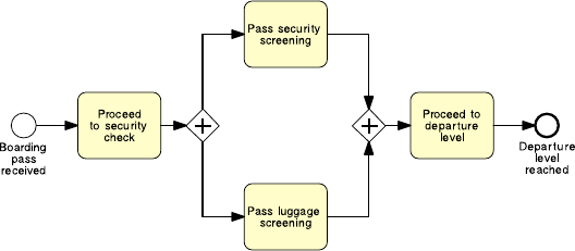
70 3 Essential Process Modeling
Fig. 3.5 An example of the use of AND gateways
undergoing the required security checks. After the first activity, and before the last
one, we need to perform two activities which can be executed in any order, i.e. which
do not depend on each other: “Pass personal security screening” and “Pass luggage
screening”. To model this situation we use an AND-split linking activity “Proceed
to security check” with the two screening activities, and an AND-join linking the
two screening activities with activity “Proceed to departure level” (see Fig. 3.5).
The AND-split splits the token coming from activity “Proceed to security check”
into two tokens. Each of these tokens independently flows through one of the two
branches. This means that when we reach an AND-split, we take all outgoing
branches (note that an AND-split may have multiple outgoing arcs). As we said
before, a token is used to indicate the state of a given instance. When multiple to-
kens of the same color are distributed across a process model, e.g. as a result of
executing an AND-split, they collectively represent the state of an instance. For ex-
ample, if a token is on the arc emitting from activity “Pass luggage screening” and
another token of the same color is on the arc incident to activity “Pass personal
security screening”, this indicates an instance of the security check process where
a passenger has just passed the luggage screening but not yet started the personal
security screening.
The AND-join of our example waits for a token to arrive from each of the two
incoming arcs, and once they are all available, it merges the tokens back into one.
The single token is then sent to activity “Proceed to departure level”. This means that
we proceed when all incoming branches have completed (note again that an AND-
join may have multiple incoming arcs). This behavior of waiting for a number of
tokens to arrive and then merging the tokens into one is called synchronization.
Example 3.4 Let us extend the order fulfillment example of Fig. 3.1 by assuming
that a purchase order is only confirmed if the product is in stock, otherwise the pro-
cess completes by rejecting the order. Further, if the order is confirmed, the shipment
address is received and the requested product is shipped while the invoice is emit-
ted and the payment is received. Afterwards, the order is archived and the process
completes.
The resulting model is shown in Fig. 3.6. Let us make a couple of remarks. First,
this model has two activities that are mutually exclusive: “Confirm order” and “Re-

3.2 Branching and Merging 71
Fig. 3.6 A more elaborated version of the order fulfillment process diagram
ject order”, thus we preceded them with an XOR-split (remember to put an activity
before an XOR-split to allow the decision to be taken, such as a check like in this
case, or an approval). Second, the two sequences “Get shipment address”–“Ship
product” and “Emit invoice”–“Receive payment” can be performed independently
of each other, so we put them in a block between an AND-split and an AND-join. In
fact, these two sets of activities are typically handled by different resources within
a seller’s organization, like a sales clerk for the shipment and a financial officer for
the invoice, and thus can be executed in parallel (note the word “meantime” in the
process description, which indicates that two or more activities can be performed at
the same time).
Let us compare this new version of the order fulfillment process with that in
Fig. 3.1 in terms of events. The new version features two end events while the first
version features one end event. In a BPMN model we can have multiple end events,
each capturing a different outcome of the process (e.g. balance paid vs. arrears pro-
cessed, order approved vs. order rejected). BPMN adopts the so-called implicit ter-
mination semantics, meaning that a process instance completes only when each to-
ken flowing in the model reaches an end event. Similarly, we can have multiple start
events in a BPMN model, each event capturing a different trigger to start a process
instance. For example, we may start our order fulfillment process either when a new
purchase order is received or when a revised order is resubmitted. If a revised order
is resubmitted, we first retrieve the order details from the orders database, and then
continue with the rest of the process. This variant of the order fulfillment model is
showninFig.3.7. An instance of this process model is triggered by the first event
that occurs (note the use of an XOR-join to merge the branches coming from the
two start events).
Exercise 3.2 Model the following fragment of a business process for assessing loan
applications.
A loan application is approved if it passes two checks: (i) the applicant’s loan risk assess-
ment, done automatically by a system, and (ii) the appraisal of the property for which the
loan has been asked, carried out by a property appraiser. The risk assessment requires a

72 3 Essential Process Modeling
Fig. 3.7 A variant of the order fulfillment process with two different triggers
credit history check on the applicant, which is performed by a financial officer. Once both
the loan risk assessment and the property appraisal have been performed, a loan officer can
assess the applicant’s eligibility. If the applicant is not eligible, the application is rejected,
otherwise the acceptance pack is prepared and sent to the applicant.
There are two situations when a gateway can be omitted. An XOR-join can be
omitted before an activity or event. In this case, the incoming arcs to the XOR-join
are directly connected to the activity/event. An example of this shorthand notation
isshowninFig.1.6, where there are two incident arcs to activity “Select suitable
equipment”. An AND-split can also be omitted when it follows an activity or event.
In this case, the outgoing arcs of the AND-split emanate directly from the activ-
ity/event.
3.2.3 Inclusive Decisions
Sometimes we may need to take one or more branches after a decision activity.
Consider the following business process.
Example 3.5 Order distribution process.
A company has two warehouses that store different products: Amsterdam and Hamburg.
When an order is received, it is distributed across these warehouses: if some of the relevant
products are maintained in Amsterdam, a sub-order is sent there; likewise, if some relevant
products are maintained in Hamburg, a sub-order is sent there. Afterwards, the order is
registered and the process completes.
Can we model the above scenario using a combination of AND and XOR gate-
ways? The answer is yes. However, there are some problems. Figures 3.8 and 3.9
show two possible solutions. In the first one, we use an XOR-split with three alter-
native branches: one taken if the order only contains Amsterdam products (where
the sub-order is forwarded to the Amsterdam warehouse), another taken if the order
only contains Hamburg products (similarly, in this branch the sub-order is forwarded

3.2 Branching and Merging 73
Fig. 3.8 Modeling an inclusive decision: first trial
Fig. 3.9 Modeling an inclusive decision: second trial
to the Hamburg warehouse), and a third branch to be taken in case the order con-
tains products from both warehouses (in which case sub-orders are forwarded to
both warehouses). These three branches converge in an XOR-join which leads to
the registration of the order.
While this model captures our scenario correctly, the resulting diagram is some-
what convoluted, since we need to duplicate the two activities that forward sub-
orders to the respective warehouses twice. And if we had more than two warehouses,
the number of duplicated activities would increase. For example, if we had three
warehouses, we would need an XOR-split with seven outgoing branches, and each
activity would need to be duplicated four times. Clearly this solution is not scal-
able.

74 3 Essential Process Modeling
Fig. 3.10 Modeling an inclusive decision with the OR gateway
In the second solution we use an AND-split with two outgoing arcs, each
of which leads to an XOR-split with two alternative branches. One is taken
if the order contains Amsterdam (Hamburg) products, in which case an ac-
tivity is performed to forward the sub-order to the respective warehouse; the
other branch is taken if the order does not contain any Amsterdam (Hamburg)
products, in which case nothing is done until the XOR-join, which merges
the two branches back. Then an AND-join merges the two parallel branches
coming out of the AND-split and the process completes by registering the or-
der.
What is the problem with this second solution? The example scenario allows
three cases: the products are in Amsterdam only, in Hamburg only, or in both ware-
houses, while this solution allows one more case, i.e. when the products are in
neither of the warehouses. This case occurs when the two empty branches of the
two XOR-splits are taken and results in doing nothing between activity “Check or-
der line items” and activity “Register order”. Thus this solution, despite being more
compact than the first one, is wrong.
To model situations where a decision may lead to one or more options be-
ing taken at the same time, we need to use an inclusive (OR) split gateway.An
OR-split is similar to the XOR-split, but the conditions on its outgoing branches
do not need to be mutually exclusive, i.e. more than one of them can be true
at the same time. When we encounter an OR-split, we thus take one or more
branches depending on which conditions are true. In terms of token seman-
tics, this means that the OR-split takes the input token and generates a num-
ber of tokens equivalent to the number of output conditions that are true, where
this number can be at least one and at most as the total number of outgoing
branches. Similar to the XOR-split gateway, an OR-split can also be equipped
with a default flow, which is taken only when all other conditions evaluate to
false.
Figure 3.10 shows the solution to our example using the OR gateway. After the
sub-order has been forwarded to either of the two warehouses or to both, we use
an OR-join to synchronize the flow and continue with the registration of the order.
An OR-join proceeds when all active incoming branches have completed. Waiting
for an active branch means waiting for an incoming branch that will ultimately de-

3.2 Branching and Merging 75
Fig. 3.11 What type should the join gateway have such that instances of this process can complete
correctly?
liver a token to the OR-join. If the branch is active, the OR-join will wait for that
token, otherwise it will not. Once all tokens of active branches have arrived, the
OR-join synchronizes these tokens into one (similarly to what an AND-join does)
and sends that token to its output arc. We call this behavior synchronizing merge
as opposed to the simple merge of the XOR-join and the synchronization of the
AND-join.
Let us delve into the concept of active branch. Consider the model in Fig. 3.11,
which features a join gateway with undefined type (the one grayed out with a ques-
tion mark). What type should we assign to this join? Let us try an AND-join to
match the preceding AND-split. We recall that an AND-join waits for a token to ar-
rive from each incoming branch. While the token from the branch with activity “C”
will always arrive, the token from the branch with activities “B” and “D” may not
arrive if this is routed to “E” by the XOR-split. So if activity “D” is not executed,
the AND-join will wait indefinitely for that token, with the consequence that the
process instance will not be able to progress any further. This behavioral anomaly
is called deadlock and should be avoided.
Let us try an XOR-join. We recall that the XOR-join works as a passthrough
by forwarding to its output branch each token that arrives through one of its input
branches. In our example this means that we may execute activity “F” once or twice,
depending whether the preceding XOR-split routes the token to “E” (in this case “F”
is executed once) or to “D” (“F” is executed twice). While this solution may work,
we have the problem that we do not know whether activity “F” will be executed
once or twice, and we may actually not want to execute it twice. Moreover, if this
is the case, we would signal that the process has completed twice, since the end
event following “F” will receive two tokens. And this, again, is something we want
to avoid.
76 3 Essential Process Modeling
The only join type left to try is the OR-join. An OR-join will wait for all incoming
active branches to complete. If the XOR-split routes control to “E”, the OR-join will
not wait for a token from the branch bearing activity “D”, since this will never arrive.
Thus, it will proceed once the token from activity “C” arrives. On the other hand, if
the XOR-split routes control to “D”, the OR-join will wait for a token to also arrive
from this branch, and once both tokens have arrived, it will merge them into one and
send this token out, so that “F” can be executed once and the process can complete
normally.
Question When should we use an OR-join?
Since the OR-join semantics is not simple, the presence of this element in a
model may confuse the reader. Thus, we suggest to use it only when it is strictly
required. Clearly, it is easy to see that an OR-join must be used whenever we need
to synchronize control from a preceding OR-split. Similarly, we should use an AND-
join to synchronize control from a preceding AND-split and an XOR-join to merge
a set of branches that are mutually exclusive. In other cases the model will not have
a lean structure like the examples in Fig. 3.8 or 3.10, where the model is made up of
nested blocks each delimited by a split and a join of the same type. The model may
rather look like that in Fig. 3.11, where there can be entry points into, or exist points
from a block-structure. In these cases play the token game to understand the correct
join type. Start with an XOR-join; next try an AND-join and if both gateways lead
to incorrect models use the OR-join which will work for sure.
Now that we have learned the three core gateways, let us use them to extend
the order fulfillment process. Assume that if the product is not in stock, it can be
manufactured. In this way, an order can never be rejected.
Example 3.6
If the product requested is not in stock, it needs to be manufactured before the order handling
can continue. To manufacture a product, the required raw materials have to be ordered. Two
preferred suppliers provide different types of raw material. Depending on the product to
be manufactured, raw materials may be ordered from either Supplier 1 or Supplier 2, or
from both. Once the raw materials are available, the product can be manufactured and the
order can be confirmed. On the other hand, if the product is in stock, it is retrieved from the
warehouse before confirming the order. Then the process continues normally.
The model for this extended order fulfillment process is shown in Fig. 3.12.
Exercise 3.3 Model the following fragment of a business process for assessing loan
applications.
A loan application may be coupled with a home insurance which is offered at discounted
prices. The applicant may express their interest in a home insurance plan at the time of
submitting their loan application to the loan provider. Based on this information, if the
loan application is approved, the loan provider may either only send an acceptance pack
to the applicant, or also send a home insurance quote. The process then continues with the
verification of the repayment agreement.

3.2 Branching and Merging 77
Fig. 3.12 The order fulfillment process diagram with product manufacturing
3.2.4 Rework and Repetition
So far we have seen structures that are linear, i.e. each activity is performed at most
once. However, sometimes we may require to repeat one or several activities, for
instance because of a failed check.
Example 3.7
In the treasury minister’s office, once a ministerial inquiry has been received, it is first
registered into the system. Then the inquiry is investigated so that a ministerial response
can be prepared. The finalization of a response includes the preparation of the response
itself by the cabinet officer and the review of the response by the principal registrar. If the
registrar does not approve the response, the latter needs to be prepared again by the cabinet
officer for review. The process finishes only once the response has been approved.
To model rework or repetition we first need to identify the activities, or more
in general the fragment of the process, that can be repeated. In our example this
consists of the sequence of activities “Prepare ministerial response” and “Review
ministerial response”. Let us call this our repetition block. The property of a repeti-
tion block is that the last of its activities must be a decision activity. In fact, this will
allow us to decide whether to go back before the repetition block starts, so that this
can be repeated, or to continue with the rest of the process. As such, this decision
activity should have two outcomes. In our example the decision activity is “Review
ministerial response” and its outcomes are: “response approved” (in this case we
continue with the process) and “response not approved” (we go back). To model
these two outcomes, we use an XOR-split with two outgoing branches: one which
allows us to continue with the rest of the process (in our example, this is simply

78 3 Essential Process Modeling
Fig. 3.13 A process model for addressing ministerial correspondence
the end event “Ministerial correspondence addressed”), the other which goes back
to before activity “Prepare ministerial response”. We use an XOR-join to reconnect
this branch to the point of the process model just before the repetition block. The
model for our example is illustrated in Fig. 3.13.
Question Why do we need to merge the loopback branch of a repetition block with
an XOR-join?
The reason for using an XOR-join is that this gateway has a very simple seman-
tics: it moves any token it receives in its input arc to its output arc, which is what
we need in this case. In fact, if we merged the loopback branch with the rest of the
model using an AND-join we would deadlock since this gateway would try to syn-
chronize the two incoming branches when we know that only one of them can be
active at a time: if we were looping we would receive the token from the loopback
branch; otherwise we would receive it from the other branch indicating that we are
entering the repetition block for the first time. An OR-join would work but is an
overkill since we know that only one branch will be active at a time.
Exercise 3.4 Model the following fragment of a business process for assessing loan
applications.
Once a loan application is received by the loan provider, and before proceeding with its
assessment, the application itself needs to be checked for completeness. If the application is
incomplete, it is returned to the applicant, so that they can fill out the missing information
and send it back to the loan provider. This process is repeated until the application is found
complete.
We have learned how to combine activities, events, and gateways to model basic
business processes. For each such element we have showed its graphical represen-
tation, the rules for combining it with other modeling elements and explained its
behavior in terms of token rules. All these aspects fall under the term components of
a modeling language. If you want to know more about this topic, you can read the
box “Components of a modeling language”.
COMPONENTS OF A MODELING LANGUAGE
A modeling language consists of three parts: syntax, semantics, and notation.
The syntax provides a set of modeling elements and a set of rules to govern

3.3 Information Artifacts 79
how these elements can be combined. The semantics bind the syntactical ele-
ments and their textual descriptions to a precise meaning. The notation defines
a set of graphical symbols for the visualization of the elements.
For example, the BPMN syntax includes activities, events, gateways, and
sequence flows. An example of syntactical rule is that start events only have
outgoing sequence flows whereas end events only have incoming sequence
flows. The BPMN semantics describes which kind of behavior is represented
by the various elements. In essence, this relates to the question how the ele-
ments can be executed in terms of token flow. For example, an AND-join has
to wait for all incoming branches to complete before it can pass control to its
outgoing branch. An example of BPMN notation is the use of labeled rounded
boxes to depict activities.
3.3 Information Artifacts
As shown in Chap. 2, a business process entails different organizational aspects
such as functions, business artifacts, humans, and software systems. These aspects
are captured by different process modeling perspectives. So far we have seen the
functional perspective, which indicates what activities should happen in the pro-
cess, and the control-flow perspective, which indicates when activities and events
should occur. Another important perspective that we ought to consider when model-
ing business processes is the data perspective. The data perspective indicates which
information artifacts (e.g. business documents, files) are required to perform an ac-
tivity and which ones are produced as a result of performing an activity.
Let us enrich the order fulfillment process of Example 3.6 with artifacts. Let us
start by identifying the artifacts that each activity requires in order to be executed,
and those that each activity creates as a result of its execution. For example, the first
activity of the order fulfillment process is “Check stock availability”. This requires
a Purchase order as input in order to check whether or not the ordered product is
in stock. This artifact is also required by activity “Check raw materials availability”
should the product be manufactured. Artifacts like Purchase order are called data
objects in BPMN. Data objects represent information flowing in and out of activi-
ties; they can be physical artifacts such as an invoice or a letter on a piece of paper,
or electronic artifacts such as an e-mail or a file. We depict them as a document with
the upper-right corner folded over, and link them to activities with a dotted arrow
with an open arrowhead (called data association in BPMN). Figure 3.14 shows the
data objects involved in the order fulfillment process model.
We use the direction of the data association to establish whether a data object is
an input or output for a given activity. An incoming association, like the one used
from Purchase order to activity “Check stock availability”, indicates that Purchase
order is an input object for this activity; an outgoing association, like the one used

80 3 Essential Process Modeling
Fig. 3.14 The order fulfillment example with artifacts
from activity “Obtain raw materials from Supplier 1” to Raw materials, indicates
that Raw materials is an output object for this activity. To avoid cluttering the dia-
gram with data associations that cross sequence flows, we may repeat a data object
multiple times within the same process model. However, all occurrences of a given
object do conceptually refer to the same artifact. For example, in Fig. 3.14 Purchase
order is repeated twice as input to “Check stock availability” and to “Confirm order”
since these two activities are far away from each other in terms of model layout.
Often the output from an activity coincides with the input to a subsequent activity.
For example, once Raw materials have been obtained, these are used by activity
“Manufacture product” to create a Product. The Product in turn is packaged and
sent to the customer by activity “Ship product”. Effectively, data objects allow us
to model the information flow between process activities. Bear in mind, however,
that data objects and their associations with activities cannot replace the sequence
flow. In other words, even if an object is passed from an activity A to an activity B,
we still need to model the sequence flow from A to B. A shorthand notation for
passing an object from an activity to the other is by directly connecting the data
object to the sequence flow between two consecutive activities via an undirected
association. See for example the Shipment address being passed from activity “Get
3.3 Information Artifacts 81
shipment address” to activity “Ship product”, which is a shorthand for indicating
that Shipment address is an output of “Get shipment address” and an input to “Ship
product”.
Sometimes we may need to represent the state of a data object. For instance,
activity “Confirm order” takes a Purchase order as input, and returns a “confirmed”
Purchase order as output: input and output objects are the same, but the object’s
state has changed to “confirmed”. Similarly, activity “Receive payment” takes as
input a “confirmed” Purchase order and transforms it into a “paid” Purchase order.
An object can go through a number of states, e.g. an invoice is first “opened”, then
“approved” or “rejected” and finally “archived”. Indicating data objects’ states is
optional: we can do so by appending the name of the state between square brackets
to a data object’s label, e.g. “Purchase Order [confirmed]”, “Product [packaged]”.
A data store is a place containing data objects that need to be persisted beyond
the duration of a process instance, e.g. a database for electronic artifacts or a fil-
ing cabinet for physical ones. Process activities can read/write data objects from/to
data stores. For example, activity “Check stock availability” retrieves the Stock lev-
els for the ordered product from the Warehouse database, which contains Stock
level information for the various Products. Similarly, activity “Check raw materials
availability” consults the Suppliers catalog to check which Supplier to contact. The
Warehouse database or the Supplier catalog are examples of data stores used as input
to activities. An example of data store employed as output is the Orders database,
which is used by activity “Archive order” to store the confirmed Purchase order. In
this way, the order just archived will be available for other business processes within
the same organization, e.g. for a business process that handles requests for prod-
uct returns. Data stores are represented as an empty cylinder (the typical database
symbol) with a triple upper border. Similar to data objects, they are connected to
activities via data associations.
Question Do data objects affect the token flow?
Input data objects are required for an activity to be executed. Even if a token
is available on the incoming arc of that activity, the latter cannot be executed until
all input data objects are also available. A data object is available if it has been
created as a result of completing a preceding activity (whose output was the data
object itself), or because it is an input to the whole process (like Purchase order).
Output data objects only affect the token flow indirectly, i.e. when they are used by
subsequent activities.
Question Do we always need to model data objects?
Data objects help the reader understand the flow of business data from one activ-
ity to the other. However, the price to pay is an increased complexity of the diagram.
Thus, we suggest to use them only when they are needed for a specific purpose, e.g.
to highlight potential issues in the process under analysis (cf. Chaps. 6 and 7)orfor
automation (cf. Chap. 9).
82 3 Essential Process Modeling
Sometimes we may need to provide additional information to the process model
reader, for the sake of improving the understanding of the model. For example, in
the order fulfillment process we may want to specify that activity “Ship product”
includes the packaging of the product. Also, we may want to clarify what business
rule is followed behind the choice of raw materials from Suppliers. Such additional
information can be provided via text annotations. An annotation is depicted as an
open-ended rectangle encapsulating the text of the annotation, and is linked to a
process modeling element via a dotted line (called association)—see Fig. 3.14 for
an example. Text annotations do not bear any semantics, thus they do not affect the
flow of tokens through the process model.
Exercise 3.5 Put together the four fragments of the loan assessment process that
you created in Exercises 3.1–3.4.
Hint Look at the labels of the start/end events to understand the order dependencies
among the various fragments. Then extend the resulting model by adding all the
required artifacts. Moreover, attach annotations to specify the business rules behind
(i) checking an application completeness, (ii) assessing an application eligibility,
and (iii) verifying a repayment agreement.
3.4 Resources
A further aspect we need to consider when modeling business processes is the re-
source perspective. This perspective, also called the organizational perspective,in-
dicates who or what performs which activity. Resource is a generic term to refer to
anyone or anything involved in the performance of a process activity. A resource
can be:
• A process participant, i.e. an individual person like the employee John Smith.
• A software system, for example a server or a software application.
• An equipment, such as a printer or a manufacturing plant.
We distinguish between active resources, i.e. resources that can autonomously
perform an activity, and passive resources, i.e. resources that are merely involved in
the performance of an activity. For example, a photocopier is used by a participant to
make a copy of a document, but it is the participant who performs the photocopying
activity. So, the photocopier is a passive resource while the participant is an active
resource. A bulldozer is another example of a passive resource since it is the driver
who performs the activity in which the bulldozer is used.
The resource perspective of a process is interested in active resources, so from
now on with the term “resource” we refer to an “active resource”.
Frequently, in a process model we do not explicitly refer to one resource at a
time, like for example an employee John Smith, but instead we refer to a group of
resources that are interchangeable in the sense that any member of the group can

3.4 Resources 83
perform a given activity. Such groups are called resource classes. Examples are a
whole organization, an organizational unit or a role.
1
Let us examine the resources involved in our order fulfillment example.
Example 3.8
The order fulfillment process is carried out by a seller’s organization which includes two de-
partments: the sales department and the warehouse & distribution department. The purchase
order received by warehouse & distribution is checked against the stock. This operation is
carried out automatically by the ERP system of warehouse & distribution, which queries
the warehouse database. If the product is in stock, it is retrieved from the warehouse be-
fore sales confirm the order. Next sales emit an invoice and wait for the payment, while the
product is shipped from within warehouse & distribution. The process completes with the
order archival in the sales department. If the product is not in stock, the ERP system within
warehouse & distribution checks the raw materials availability by accessing the suppliers
catalog. Once the raw materials have been obtained the warehouse & distribution depart-
ment takes care of manufacturing the product. The process completes with the purchase
order being confirmed and archived by the sales department.
BPMN provides two constructs to model resource aspects: pools and lanes. Pools
are generally used to model resource classes, lanes are used to partition a pool into
sub-classes or single resources. There are no constraints as to what specific resource
type a pool or a lane should model. We would typically use a pool to model a busi-
ness party like a whole organization such as the seller in our example, and a lane
to model a department, unit, team or software system/equipment within that orga-
nization. In our example, we partition the Seller pool into two lanes: one for the
warehouse & distribution department, the other for the sales department.
Lanes can be nested within each other in multiple levels. For example, if we
need to model both a department and the roles within that department, we can use
one outer lane for the department, and one inner lane for each role. In the order
fulfillment example we nest a lane within Warehouse & Distribution to represent
the ERP System within that department.
Pools and lanes are depicted as rectangles within which we can place activities,
events, gateways, and data objects. Typically, we model these rectangles horizon-
tally, though modeling them vertically is also possible. The name of the pool/lane
is shown vertically on the left-hand side of a horizontal rectangle (or horizontally if
the pool/lane is vertical); for pools, and for lanes containing nested lanes , the name
is enclosed in a band. Figure 3.15 shows the revised order fulfillment example with
resource aspects.
It is important to place an activity within the right lane. For example, we placed
activity “Check stock availability” under the ERP System lane of Warehouse &
Distribution to indicate that this activity is carried out automatically by the ERP
system of that department. It is also important to place events properly within lanes.
In our example we put event “Purchase order received” under the ERP system lane to
indicate that the process starts within the ERP system of Warehouse & Distribution,
1
In BPMN the term “participant” is used in a broad sense as a synonym of resource class, though
in this book we do not adopt this definition.

84 3 Essential Process Modeling
Fig. 3.15 The order fulfillment example with resource information
3.4 Resources 85
while we put event “Order fulfilled” under the Sales pool to indicate that the process
completes in the sales department. It is not relevant where data objects are put, as
they depend on the activities they are linked to. As per gateways, we need to place
those modeling (X)OR-splits under the same lane as the preceding decision activity
has been put in. On the other hand, it is irrelevant where we place an AND-split
and all join gateways, since these elements are passive in the sense that they behave
according to their context.
We may organize lanes within a pool in a matrix when we need to model com-
plex organizational structures. For example, if we have an organization where roles
span different departments, we may use horizontal lanes to model the various de-
partments, and vertical lanes to model the roles within these departments. Bear in
mind, however, that in BPMN each activity can be performed by one resource only.
Thus, if an activity sits in the intersection of a horizontal lane with a vertical lane, it
will be performed by the resource that fulfills the characteristics of both lanes, e.g.
a resource that has that role and belongs to that department.
Exercise 3.6 Extend the business process for assessing loan applications that you
created in Exercise 3.5 by considering the following resource aspects.
The process for assessing loan applications is executed by four roles within the loan
provider: a financial officer takes care of checking the applicant’s credit history; a prop-
erty appraiser is responsible for appraising the property; an insurance sales representative
sends the home insurance quote to the applicant if this is required. All other activities are
performed by the loan officer who is the main point of contact with the applicant.
Often there is more than one business party participating in the same business
process. For example, in the order fulfillment process there are four parties: the
seller, the customer and the two suppliers.
Each party can be modeled by a pool. In our example we can thus use one pool
for the customer, one for the seller and one for each supplier. Each of these pools
will contain the activities, events, gateways, and data objects that model the specific
portion of the business process occurring at that organization. Or to put it differently,
each pool will model the same business process from the perspective of a specific
organization. For example, event “Purchase order received” which sits in the Sales
pool, will have a corresponding activity “Submit purchase order” occurring in the
Customer pool. Similarly, activity “Ship product” from Sales will have a counter-
part activity “Receive product” in the Customer pool. So, how can we model the
interactions among the pools of two collaborating organizations? We cannot use the
sequence flow to connect activities that belong to different pools since the sequence
flow cannot cross the boundary of a pool. For this, we need to use a specific element
called message flow.
A message flow represents the flow of information between two separate resource
classes (pools). It is depicted as a dashed line which starts with an empty circle
and ends with an empty arrowhead, and bears a label indicating the content of the
message, e.g. a fax, a purchase order, but also a letter or a phone call. That is, the
86 3 Essential Process Modeling
message flow models any type of communication between two organizations, no
matter if this is electronic like sending a purchase order via e-mail or transmitting a
fax, or manual like making a phone call or handing over a letter on paper.
Figure 3.16 shows the complete order fulfillment process model including the
pools for the customer and the two suppliers. Here we can see that message flows
are labeled with the piece of information they carry, e.g. “Raw materials” or “Ship-
ment address”. An incoming message flow may lead to the creation of a data ob-
ject by the activity that receives the message. For example, the message flow “Raw
materials” is received by activity “Obtain raw materials from Supplier 1” which
then creates the data object “Raw materials”. This is also the case of the purchase
order, which is generated by the start event “Purchase order received” from the
content of the incoming message flow. We do not need to create a data object for
each incoming message flow, only when the information carried by the message is
needed elsewhere in the process. In our case, “Raw materials” is consumed by ac-
tivity “Manufacture product” so we need to represent it as a data object. Similarly,
we do not need to explicitly represent the data object that goes into an outgoing
message if this data object is not needed elsewhere in the process. For example, ac-
tivity “Emit invoice” generates an invoice which is sent to the customer, but there
is no data object “Invoice” since this is not consumed by any activity in the Seller
pool.
A BPMN diagram that features two or more pools is called collaboration dia-
gram. Figure 3.16 shows different uses of a pool in a collaboration diagram. A pool
like that for the seller is called private process,orwhite box pool, since it shows
how effectively the seller organization participates in the order fulfillment process
in terms of activities, events, gateways, and data objects. On the contrary, a pool
like that for the customer and the two suppliers is called public process,orblack
box pool, since it hides how these organizations actually participate in the order
fulfillment process. In order to save space, we can represent a black box with a
collapsed pool, which is an empty rectangle bearing the name of the pool in the
middle.
Question Black box or white box?
Modeling a pool as a white box or as a black box is a matter of relevance. When
working on a collaboration diagram, an organization may decide whether or not
to expose their internal behavior depending on the requirements of the project at
hand. For example, if we are modeling the order fulfillment process from the seller’s
perspective, it may be relevant to expose the business process of the seller only,
but not that of the customer and the suppliers. That is, the internal behavior of the
customer and that of the suppliers are not relevant for the sake of understanding
how the seller should fulfill purchase orders, and as such they can be hidden. On
the other hand, if we need to improve the way the seller fulfills purchase orders, we
may also want to know what it takes for a supplier to provide raw materials, as a
delay in the provision of raw materials will slow down the product manufacturing

3.4 Resources 87
Fig. 3.16 Collaboration diagram between a seller, a customer and two suppliers

88 3 Essential Process Modeling
at the seller’s side. In this case, we should also represent the suppliers using white
box pools.
The type of pool affects the way we use the message flow to connect to the
pool. Accordingly, a message flow may cross the boundary of a white box pool
and connect directly to an activity or event within that pool, like the Purchase order
message which is incident to the start event in the Seller pool. On the other hand,
since a black box pool is empty, message flows must stop at the boundary or emanate
from the boundary of a black box pool. Bear in mind that a message flow is only
used to connect two pools and never to connect two activities within the same pool.
For that, we use a sequence flow.
An activity that is the source of a message—such as “Emit invoice” in the Seller
pool—is called a send activity. The message is sent upon completion of the activity’s
execution. On the other hand, an activity that receives a message—such as “Get
shipping address”—is a receive activity.
2
The execution of such an activity will not
start until the incoming message is available. An activity can act as both a receive
and a send activity when it has both an incoming and outgoing message flow, e.g.
“Make payment”. The execution of this activity will start when both the control-flow
token and the incoming message are available. Upon completion of the activity, a
control-flow token will be put on the output arc and the outgoing message will be
sent out. Finally, when a message flow is incident to a start event like “Purchase
order received”, we need to mark this event with a light envelope (see Fig. 3.16).
This event type is called message event. A message event can be linked to an output
data object in order to store the content of the incoming message. We will learn
more about events in the next chapter.
Exercise 3.7 Extend the model of Exercise 3.6 by representing the interactions be-
tween the loan provider and the applicant.
In the order fulfillment example we used pools to represent business parties and
lanes to represent the departments and systems within the sales organization. This is
because we wanted to focus on the interactions between the seller, the customer and
the two suppliers. As mentioned before, this is the typical use for pools and lanes.
However, since BPMN does not prescribe what specific resource types should be
associated with pools and lanes, we may use these elements differently. For exam-
ple, if the focus is on the interactions between the departments of an organization,
we can model each department with a pool, and use lanes to partition the depart-
ments, e.g. in units or roles. In any case, we should avoid to use pools and lanes
to capture participants by their names since individuals tend to change frequently
within an organization; rather, we should use the participant’s role, e.g. financial
officer. On the other hand, we can use pools and lanes to represent specific software
systems or equipments, e.g. an ERP system, since these change less frequently in an
organization.
2
More specifically, “Emit invoice” is a send task and “Get shipping address” is a receive task.The
distinction between activity and task will be discussed in Chap. 4.

3.5 Recap 89
3.5 Recap
At the end of this chapter, we should be able to understand and produce basic pro-
cess models in BPMN. A basic BPMN model includes simple activities, events,
gateways, data objects, pools, and lanes. Activities capture units of work within a
process. Events define the start and end of a process, and signal something that hap-
pens during the execution of it. Gateways model exclusive and inclusive decisions,
merges, parallelism and synchronization, and repetition. We studied the difference
between process model and process instance. A process model depicts all the possi-
ble ways a given business process can be executed, while a process instance captures
one specific process execution out of all possible ones. The progress, or state, of a
process instance is represented by tokens. Using tokens we can define the behavior
of gateways.
We also learned how to use data objects to model the information flow between
activities and events. A data object captures a physical or an electronic artifact re-
quired to execute an activity or trigger an event, or that results from the execution
of an activity or an event occurrence. Data objects can be stored in a data store
like a database or file cabinet such that they can be persisted beyond the process
instance where they are created. Furthermore, we saw how pools and lanes can be
used to model both human and non-human resources that perform process activi-
ties. Pools generally model resource classes while lanes are used to partition pools.
The interaction between pools is captured by message flows. Message flows can be
directly attached to the boundary of a pool, should the details of the interaction not
be relevant.
Activities, events, gateways, artifacts, and resources belong to the main model-
ing perspectives of a business process. The functional perspective captures the ac-
tivities that are performed in a business process while the control-flow perspective
combines these activities and related events in a given order. The data perspective
covers the artifacts manipulated in the process while the resource perspective covers
the resources that perform the various activities. In the next chapter, we will learn
how to model complex business processes by delving into the various extensions of
the core BPMN elements that we presented here.
3.6 Solutions to Exercises
Solution 3.1

90 3 Essential Process Modeling
Solution 3.2
Solution 3.3
Solution 3.4

3.6 Solutions to Exercises 91
Solution 3.5

92 3 Essential Process Modeling
Solution 3.6 See the Loan Provider pool in the model of Solution 3.7.
Solution 3.7

3.7 Further Exercises 93
3.7 Further Exercises
Exercise 3.8 What types of splits and joins can we model in a process? Make an
example for each of them using the security check at an airport as a scenario.
Exercise 3.9 Describe the following process model.
Exercise 3.10 Model the following business process for handling downpayments.
The process for handling downpayments starts when a request for payment has been ap-
proved. It involves entering the downpayment request into the system, the automatic sub-
sequent payment, emission of the direct invoice and the clearance of the vendor line items.
The clearing of the vendor line items can result in a debit or credit balance. In case of debit
balance, the arrears are processed, otherwise the remaining balance is paid.
Exercise 3.11 Model the following business process for assessing credit risks.
When a new credit request is received, the risk is assessed. If the risk is above a threshold,
an advanced risk assessment needs to be carried out, otherwise a simple risk assessment will
suffice. Once the assessment has been completed, the customer is notified with the result of
the assessment and meantime the disbursement is organized. For simplicity, assume that the
result of an assessment is always positive.
Exercise 3.12 Model the following fragment of a business process for insurance
claims.
After a claim is registered, it is examined by a claims officer who then writes a settlement
recommendation. This recommendation is then checked by a senior claims officer who may
mark the claim as “OK” or “Not OK”. If the claim is marked as “Not OK”, it is sent back
to the claims officer and the recommendation is repeated. If the claim is “OK”, the claim
handling process proceeds.
Exercise 3.13 Model the control flow of the following business process for damage
compensation.
If a tenant is evicted because of damages to the premises, a process needs to be started by the
tribunal in order to hold a hearing to assess the amount of compensation the tenant owes the
owner of the premises. This process starts when a cashier of the tribunal receives a request
for compensation from the owner. The cashier then retrieves the file for those particular
premises and checks that both the request is acceptable for filing, and compliant with the

94 3 Essential Process Modeling
description of the premises on file. Setting a hearing date incurs fees to the owner. It may be
that the owner has already paid the fees with the request, in which case the cashier allocates
a hearing date and the process completes. It may be that additional fees are required, but the
owner has already paid also those fees. In this case the cashier generates a receipt for the
additional fees and proceeds with allocating the hearing date. Finally, if the owner has not
paid the required fees, the cashier produces a fees notice and waits for the owner to pay the
fees before reassessing the document compliance.
Exercise 3.14 Can the process model below execute correctly? If not, how can it
be fixed without affecting the cycle, i.e. such that “F”, “G”, and “E” all remain in
the cycle?
Exercise 3.15 Write a BPMN model for the process described in Exercise 1.1.
Make sure to include artifacts and annotations where appropriate.
Exercise 3.16 Extend the model of Exercise 3.13 by adding the artifacts that are
manipulated.
Exercise 3.17 Extend the model of Exercise 3.16 by adding the involved resources.
Is there any non-human resource?
Exercise 3.18 Model the following business process. Use gateways and data objects
where needed.
In a court each morning the files that have yet to be processed are checked to make sure
they are in order for the court hearing that day. If some files are missing a search is initiated,
otherwise the files can be physically tracked to the intended location. Once all the files are
ready, these are handed to the Associate; meantime the judge’s lawlist is distributed to the
relevant people. Afterwards, the directions hearings are conducted.
Exercise 3.19 Model the following business process. Use pools/lanes where
needed.
The motor claim handling process starts when a customer submits a claim with the relevant
documentation. The notification department at the car insurer checks the documents upon
3.8 Further Reading 95
completeness and registers the claim. Next, the Handling department picks up the claim
and checks the insurance. Then, an assessment is performed. If the assessment is positive,
a Garage is phoned to authorize the repairs and the payment is scheduled (in this order).
Otherwise, the claim is rejected. In any case (whether the outcome is positive or negative),
a letter is sent to the customer and the process is considered to be complete.
Exercise 3.20 Model the following business process. Use pools/lanes where
needed.
When a claim is received, a claims officer first checks if the claimant is insured. If not, the
claimant is informed that the claim must be rejected by sending an automatic notification via
an SAP system. Otherwise, a senior claims officer evaluates the severity of the claim. Based
on the outcome (simple or complex claims), the relevant forms are sent to the claimant,
again using the SAP system. Once the forms are returned, they are checked for completeness
by the claims officer. If the forms provide all relevant details, the claim is registered in the
claims management system, and the process ends. Otherwise, the claimant is informed to
update the forms via the SAP system. Upon reception of the updated forms, they are checked
again by the claims officer to see if the details have been provided, and so on.
3.8 Further Reading
In this chapter we presented the basics of process modeling through the BPMN
language. Other mainstream languages that can be used to model business processes
are UML Activity Diagrams (UML ADs), Event-driven Process Chains (EPCs) and
Web Services Business Process Execution Language (WS-BPEL). UML ADs are
another OMG standard [60]. They are mainly employed in software engineering
where they can be used to describe software behavior and linked to other UML
diagram types, e.g. class diagrams, to generate software code. UML ADs offer a
subset of the modeling elements present in BPMN. For example, constructs like the
OR-join are not supported. A good overview of this language and its application to
business process modeling is provided in [16].
EPCs were initially developed for the design of the SAP R/3 reference process
model [9]. They obtained a widespread adoption by various organizations when they
became the core modeling language of the ARIS toolset [12, 82]. Later, they were
used by other vendors for the design of SAP-independent reference models such as
ITIL and SCOR. The EPC language includes modeling elements corresponding to
BPMN activities, AND, XOR and OR gateways, untyped events and data objects.
An introduction to EPCs is provided in [50].
WS-BPEL (BPEL for short) version 2.0 [3] is a standard of the Organization for
the Advancement of Structured Information Standards (OASIS). A good overview
of BPEL is provided in [65]. BPEL is a language for process execution which re-
lies on Web service technology to achieve inter-process communication. A mapping
from BPMN to BPEL constructs is available in the BPMN specification [61]. How-
ever, this mapping is not complete since BPEL offers a restricted set of constructs
compared to BPMN, and is essentially a block-oriented language, while BPMN is
graph-oriented. BPEL is structured in blocks which need to be properly nested and
96 3 Essential Process Modeling
cannot overlap. A block is made up of a single entry node and a single exit node
which matches the type of the entry node and collects all the outgoing branches
from the entry node. For example, if the entry node is an AND-split, the exit node
must be an AND-join. Moreover, BPEL does not feature a standard notation, since
this was deemed to be out of scope by OASIS, though various vendors provide pro-
prietary notations for this language. While BPMN 1.2 aimed to be the conceptual
counterpart of BPEL, and mappings were thus available to move from the former to
the latter language, BPMN 2.0 can also be used to specify executable processes (see
Chap. 9). Thus BPMN 2.0 aims to replace BPEL in this respect.
Other process modeling languages originate from research efforts. Two of them
are Workflow nets and Yet Another Workflow Language (YAWL). Workflow nets
are an extension of Petri nets to model business processes. Their syntax is purpose-
fully simple and revolves around two elements: places and transitions. The former
roughly correspond to BPMN events, while the latter to BPMN activities. A good
presentation of Workflow nets is provided in [95].
YAWL is a successor of Workflow nets in that it adds specific constructs to cap-
ture the OR-join behavior, multi-instance activities, sub-processes and cancellation
regions. YAWL retains the simplicity and intuitiveness of Workflow nets, though it
provides a much more expressive language. YAWL and its supporting environment
are presented in detail in [92].
A comparison of the above languages in terms of their expressiveness along the
control-flow, data and resource perspectives can be found in the Workflow Patterns
Initiative website [108]. Over time this initiative has collected a repository of work-
flow patterns, i.e. recurring process behavior as it has been observed from a thor-
ough analysis of various process modeling languages and supporting tools. Various
languages and tools have been compared based on their support for such patterns.
Chapter 4
Advanced Process Modeling
The sciences do not try to explain, they hardly even try to
interpret, they mainly make models.
John von Neumann (1903–1957)
In this chapter we will learn how to model complex business processes with BPMN.
The constructs presented in this chapter build on top of the knowledge acquired
in Chap. 3. In particular, we will expand on activities, events and gateways. We
will learn how to use activities to model sub-processes and how to reuse these sub-
processes across different processes. We will also extend activities to model more
sophisticated forms of rework and repetition. As per events, we will expand on mes-
sage events, present temporal events and show how race conditions can be modeled
among these event types via a new type of gateway. We will also learn how to use
events to handle business process exceptions. Finally, we will show how a collabo-
ration diagram can be abstracted into a choreography diagram that only focuses on
the interactions between the involved business parties.
4.1 Process Decomposition
When capturing complex business processes, the resulting process model may be
too large to be understood at once. Take the order fulfillment process model in
Fig. 3.12. While the scenario at hand is still relatively simple, this model already
contains 14 activities, six gateways and two events. As we add data objects and mes-
sage flows, the model gets larger and so harder to understand (see e.g. Fig. 3.16). To
improve its readability, we can simplify the process by hiding certain parts within
a sub-process. A sub-process represents a self-contained, composite activity that
can be broken down into smaller units of work. Conversely, an atomic activity, also
called task, is an activity capturing a unit of work that cannot be further broken
down.
In order to use a sub-process, we first need to identify groups of related activities,
i.e. those activities which together achieve a particular goal or generate a particu-
lar outcome in the process model under analysis. In our order fulfillment example,
we can see that the activities “Check raw materials availability” and “Purchase raw
M. Dumas et al., Fundamentals of Business Process Management,
DOI 10.1007/978-3-642-33143-5_4, © Springer-Verlag Berlin Heidelberg 2013
97

98 4 Advanced Process Modeling
Fig. 4.1 Identifying sub-processes in the order fulfillment process of Fig. 3.12
materials from Supplier 1(2)”, lead together to the acquisition of raw materials.
Thus these activities, and their connecting gateways, can be encapsulated in a sub-
process. In other words, they can be seen as the internal steps of a macro-activity
called “Acquire raw materials”. Similarly, the two parallel branches for shipping and
invoicing the order can be grouped under another sub-process activity called “Ship
and invoice”. Figure 4.1 illustrates the resulting model, where the above activities
have been enclosed in two sub-process activities. We represent such activities with
a large rounded box which encloses the internal steps. As we can observe from
Fig. 4.1, we also added a start event and an end event inside each sub-process activ-
ity, to explicitly indicate when the sub-process starts and completes.
Recall that our initial objective was to simplify a process model. Once we have
identified the boundaries of the sub-processes, we can simplify the model by hid-
ing the content of its sub-processes, as shown in Fig. 4.2. This is done by replacing
the macro-activity representing the sub-process with a standard-size activity. We
indicate that this activity hides a sub-process by marking it with a small square
with a plus sign (+) inside (like if we could expand the content of that activity
by pressing the plus button). This operation is called collapsing a sub-process. By
collapsing a sub-process we reduce the total number of activities (the order ful-
fillment process has only six activities now), thus improving the model readabil-
ity. In BPMN, a sub-process which hides its internal steps is called collapsed sub-
process, as opposed to an expanded sub-process which shows its internal steps (as
in Fig. 4.1).

4.1 Process Decomposition 99
Fig. 4.2 A simplified version of the order fulfillment process after hiding the content of its sub-
processes
Exercise 4.1 Identify suitable sub-processes in the process for assessing loan ap-
plications modeled in Exercise 3.5.
Hint Use the building blocks that you created throughout Exercises 3.1–3.4.
Collapsing a sub-process does not imply losing its content. The sub-process
is still there, just defined at an abstraction level below. In fact, we can nest sub-
processes in multiple levels, so as to decompose a process model hierarchically. An
example is shown in Fig. 4.3, which models a business process for disbursing home
loans. In the first level we identified two sub-processes: one for checking the appli-
cant’s liability, the other for signing the loan. In the second level, we factored out
the scheduling of the loan disbursement within the process for signing loans into a
separate sub-process.
As we go down the hierarchical decomposition of a process model, we can add
more details. For example, we may establish a convention that at the top level we
only model core business activities, at the second level we add decision points, and
so on all the way down to modeling exceptions and details that are only relevant for
process automation.
Question When should we decompose a process model into sub-processes?
We should use sub-processes whenever a model becomes too large that is hard to
understand. While it is hard to precisely define when a process model is “too large”,
since understandability is subjective, it has been shown that using more than ap-
proximately 30 flow objects (i.e. activities, events, gateways) leads to an increased
probability of making mistakes in a process model (e.g. introducing behavioral is-
sues). Thus, we suggest to use as few elements as possible per each process model
level, and in particular to decompose a process model if this has more than 30 flow
objects.
Reducing the size of a process model, for example by collapsing its sub-
processes, is one of the most effective ways of improving a process model’s read-
ability. Other structural aspects that affect the readability include the density of the

100 4 Advanced Process Modeling
Fig. 4.3 A process model for disbursing home loans, laid down over three hierarchical levels via
the use of sub-processes
process model connections, the number of parallel branches, the longest path from a
start to an end event, as well as cosmetic aspects such as the layout, the labels style
(e.g. always use a verb-noun style), the colors palette, the lines thickness, etc. More
information on establishing process modeling guidelines can be found in Chap. 5.
We have shown that we can simplify a process model by first identifying the
content of a sub-process, and then hiding this content by collapsing the sub-process
activity. Sometimes, we may wish to proceed in the opposite direction, meaning that
when modeling a process we already identify activities that can be broken down in
smaller steps, but we intentionally under-specify their content. In other words, we
do not link the sub-process activity to a process model at a lower level capturing
its content (like if by pressing the plus button nothing would happen). The reason
for doing this is to tell the reader that some activities are made up of sub-steps, but
that disclosing the details of these is not relevant. This could be the case of activity
“Ship product” in the order fulfillment example, for which modeling the distinction
between its internal steps for packaging and for shipping is not relevant.
4.2 Process Reuse
By default a sub-process is embedded within its parent process model, and as such
it can only be invoked from within that process model. Often, when modeling a
business process we may need to reuse parts of other process models of the same
organization. For example, a loan provider may reuse the sub-process for signing

4.2 Process Reuse 101
Fig. 4.4 The process model for disbursing student loans invokes the same model for signing loans
used by the process for disbursing home loans, via a call activity
loans contained in the home loan disbursement for other types of loan, such as a
process for disbursing student loans or motor loans.
In BPMN, we can define the content of a sub-process outside its parent process,
by defining the sub-process as a global process model. A global process model is
a process model that is not embedded within any process model, and as such can
be invoked by other process models within the same process model collection. To
indicate that the sub-process being invoked is a global process model, we use the
collapsed sub-process activity with a thicker border (this activity type is called call
activity in BPMN). Coming back to the loan disbursement example of Fig. 4.3,we
can factor out the sub-process for signing loans and define it as a global process
model, so that it can also be invoked by a process model for disbursing student
loans (see Fig. 4.4).
Question Embedded or global sub-process?
Our default choice should be to define sub-processes as global process models
so as to maximize their reusability within our process model collection. Supporting
processes such as payment, invoicing, HR, printing, are good candidates for being
defined as global process models, since they are typically shared by various business
processes within an organization. Besides reusability, another advantage of using
global process models is that any change made to these models will be automati-
cally propagated to all process models that invoke them. In some cases, however,
we may want to keep the changes internal to a specific process. For example, an
invoicing process used for corporate orders settlement would typically be different
102 4 Advanced Process Modeling
from the invoicing process for private orders. In this case, we should keep two model
variants of the invoice sub-process, each embedded within its parent process model:
corporate and private order settlement.
Example 4.1 Let us consider the procurement process of a pharmaceutical company.
A pharmaceutical company has different business units within its manufacturing depart-
ment, each producing a specific type of medicine. For example, there is a business unit
looking after inhaled medications, and another one producing vaccines. The various busi-
ness units make use of a direct procurement process for ordering chemicals, and of an
indirect procurement process for ordering spare parts for their equipment.
The direct procurement process depends on the raw materials that are required to
produce a specific type of medicine. For example, vaccines typically include ad-
juvants that help improve the vaccine’s effectiveness, which are not contained in
inhaled medications. Similarly, inhaled medications contain a chemical propellant
to push the medicine out of the inhaler, which is not required for vaccines. Since
this procurement process is specific to each business unit, we need to model it as
an embedded sub-process within the manufacturing process model of each unit. On
the other hand, the process for ordering spare parts to the equipment for synthesiz-
ing chemicals can be shared across all units, since all units make use of the same
equipment. Thus, we will model this process with a global process model.
Before concluding our discussion on sub-processes, we need to point to some
syntactical rules for using this element. A sub-process is a regular process model. It
should start with at least one start event, and complete with at least one end event.
If there are multiple start events, the sub-process will be triggered by the first such
an event that occurs. If there are multiple end events, the sub-process will return
control to its parent process only when each token flowing in this model reaches
an end event. Moreover, we cannot cross the boundary of a sub-process with a se-
quence flow. To pass control to a sub-process, or receive control from a sub-process,
we should always use start and end events. On the other hand, message flows can
cross the boundaries of a sub-process to indicate messages that emanate from, or are
directed to, internal activities or events of the sub-process.
Exercise 4.2 Identify suitable sub-processes in the business process of Exercise 1.7.
Among these sub-processes, identify those that are specific to this business process
versus those that can potentially be shared with other business processes of the same
company.
4.3 More on Rework and Repetition
In the previous chapter we described how to model rework and repetition via the
XOR gateways. Expanded sub-processes offer an alternative way to model parts
of a process that can be repeated. Let us consider again the process for addressing
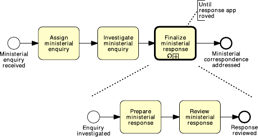
4.3 More on Rework and Repetition 103
Fig. 4.5 The process model for addressing ministerial correspondence of Fig. 3.13 simplified
using a loop activity
ministerial correspondence of Example 3.7. To make this model simpler, we can
take the fragment identified by the XOR-join and the XOR-split (which includes
the repetition block and the loopback branch) and replace it with a sub-process
containing the activities in the repetition block. To identify that this sub-process
may be repeated (if the response is not approved), we mark the sub-process activity
with a loop symbol, as shown in Fig. 4.5. We can use an annotation to specify the
loop condition, e.g. “until response approved”.
As for any sub-process, you may decide not to specify the content of a loop
sub-process. However, if you do so, do not forget to put a decision activity as the
last activity inside the sub-process, otherwise there is no way to determine when to
repeat the sub-process.
Question Loop activity or cycle?
The loop activity is a shorthand notation for a structured cycle, i.e. a repetition
block delimited by a single entry point to the cycle, and a single exit point from
the cycle, like in the example above. Sometimes there might be more than one en-
try and/or exit point, or the entry/exit point might be inside the repetition block.
Consider for example the model in Fig. 4.6. Here the repetition block is made up
of activities “Assess application”, “Notify rejection” and “Receive customer feed-
back”; the cycle has an entry point and two exit points, of which one inside the
repetition block. When an unstructured cycle has multiple exit points, like in this
case, a loop activity cannot be used, unless additional conditions are used to specify
the situations in which the cycle can be exited, which will render the model more
complex.
Exercise 4.3
1. Identify the entry and exit points that delimit the unstructured cycles in the pro-
cess models shown in Solution 3.4 and in Exercise 3.9. What are the repetition
blocks?

104 4 Advanced Process Modeling
Fig. 4.6 An example of unstructured cycle
2. Model the business process of Solution 3.4 using a loop activity.
4.3.1 Parallel Repetition
The loop activity allows us to capture sequential repetition, meaning that instances
of the loop activity are executed one after the other. Sometimes, though, we may
need to execute multiple instances of the same activity at the same time, like in the
following example.
Example 4.2 In a procurement process, a quote is to be obtained from all preferred
suppliers. After all quotes are received, they are evaluated and the best quote is
selected. A corresponding purchase order is then placed.
Let us assume five preferred suppliers exist. Then we can use an AND-split to
model five tasks in parallel, each to obtain a quote from one supplier, as shown in
Fig. 4.7. However, there are several problems with this solution. First, the larger the
number of suppliers, the larger the resulting model will be, since we need to use
one task per supplier. Second, we need to revise the model every time the number
of suppliers changes. In fact, it is often the case in reality that an updated list of
suppliers is kept in an organizational database which is queried before contacting
the suppliers.
To obviate these problems, BPMN provides a construct called multi-instance ac-
tivity. A multi-instance activity indicates an activity (being it a task or a sub-process)
that is executed multiple times concurrently. Such a construct is useful when the
same activity needs to be executed for multiple entities or data items, like for ex-
ample to request quotes from multiple suppliers (as in our example), to check the
availability of each line item in an order separately, to send and gather question-
naires for multiple witnesses in the context of an insurance claim, etc.
A multi-instance activity is depicted as an activity marked with three small ver-
tical lines at the bottom. Figure 4.8 shows a revised version of the procurement
process model in Fig. 4.7. Not only is this model smaller, but it can also work with
a dynamic list of suppliers, which may change on an instance-by-instance basis.

4.3 More on Rework and Repetition 105
Fig. 4.7 Obtaining quotes from five suppliers
To do so, we added a task to retrieve the list of suppliers, and passed this list to a
multi-instance task, which contacts the various suppliers. You would have noticed
that in this example we have also marked the data object Suppliers list with the
multi-instance symbol. This is used to indicate a collection of similar data objects,
like a list of order items, or a list of customers. When a collection is used as input
to a multi-instance activity, the number of items in the collection determines the
number of activity instances to be created. Alternatively, we can specify the number
of instances to be created via an annotation on the multi-instance activity (e.g. “15
suppliers”, or “as per suppliers database”).
Let us come back to our example. Assume the list of suppliers has become quite
large over time, say there are 20 suppliers in the database. As per our organizational
policies, however, five quotes from five different suppliers are enough to make a
decision. Thus, we do not want to wait for all 20 suppliers to reply back to our
request for quote. To do so, we can annotate the multi-instance activity with the
minimum number of instances that need to complete before passing control to the
outgoing arc (e.g. “complete when five quotes obtained”, as shown in Fig. 4.8).
When the multi-instance activity is triggered, 20 tokens are generated, each marking
the progress of one of the 20 instances. Then, as soon as the first five instances
complete, all the other instances are canceled (the respective tokens are destroyed)
and one token is sent to the output arc to signal completion.
Let us take the order fulfillment example in Fig. 4.2, and expand the content of
the sub-process for acquiring raw materials. To make this model more realistic, we
can use a multi-instance sub-process in place of the structure delimited by the two
OR gateways, assuming that the list of suppliers to be contacted will be determined

106 4 Advanced Process Modeling
Fig. 4.8 Obtaining quotes from multiple suppliers, whose number is not known a priori
Fig. 4.9 Using a multi-instance pool to represent multiple suppliers
on the fly from a suppliers database (the updated model is shown in Fig. 4.9). By the
same principle, we replace the two pools “Supplier 1” and “Supplier 2” with a single
pool, namely “Supplier”, which we also mark with the multi-instance symbol—a
multi-instance pool represents a set of resource classes, or resources, having similar
characteristics.
4.3 More on Rework and Repetition 107
From this figure we note that there are four message flows connected to the sub-
process “Ship and invoice”, as a result of collapsing the content of this activity.
The order in which these messages are exchanged is determined by the activities
inside this sub-process that receive and send them. In other words, when it comes
to a collapsed sub-process activity, the message semantics for tasks described in
Sect. 3.4 is not enforced.
Exercise 4.4 Model the following process fragment.
After a car accident, a statement is sought from two witnesses out of the five that were
present, in order to lodge the insurance claim. As soon as the first two statements are re-
ceived, the claim can be lodged with the insurance company without waiting for the other
statements.
4.3.2 Uncontrolled Repetition
Sometimes we may need to model that one or more activities can be repeated a
number of times, without a specific order, until a condition is met. For example, let
us assume that the customer of our order fulfillment process needs to inquire about
the progress of their order. The customer may do so simply by sending an e-mail to
the seller. This may be done any time after the customer has submitted the purchase
order and as often as the customer desires. Similarly, the customer may attempt to
cancel the order or update their personal details before the order has been fulfilled.
These activities are uncontrolled, in the sense that they may be repeated multiple
times with no specific order, or not occur at all, until a condition is met—in our case
the order being fulfilled.
To model a set of uncontrolled activities, we can use an ad-hoc sub-process.
Figure 4.10 shows the example of the customer’s process, where the completion
condition (“until order is fulfilled”) has been specified via an annotation. The ad-
hoc sub-process is marked with a tilde symbol at the bottom of the sub-process box.
A partial order may be established among the activities of an ad-hoc sub-process
via the sequence flow. However, we cannot represent start and end events in an ad-
hoc sub-process.
Exercise 4.5 Model the following process snippet.
A typical army recruitment process starts by shortlisting all candidates’ applications. Those
shortlisted are then called to sit the following tests: drug and alcohol, eye, color vision,
hearing, blood, urine, weight, fingerprinting and doctor examination. The color vision can
only be done after the eye test, while the doctor examination can only be done after color
vision, hearing, blood, urine and weight have been tested. Moreover, it may be required
for some candidates to repeat some of these tests multiple times in order to get a correct
assessment, e.g. the blood test may need to be repeated if the candidate has taken too much
sugar in the previous 24 hours. The candidates that pass all tests are asked to sit a mental
exam and a physical exam, followed by an interview. Only those that also pass these two
exams and perform well in the interview can be recruited in the army.

108 4 Advanced Process Modeling
Fig. 4.10 Using an ad-hoc sub-process to model uncontrolled repetition
4.4 Handling Events
As we pointed out in Chap. 3, events are used to model something that happens in-
stantaneously in a process. We saw start events, which signal how process instances
start (tokens are created), and end events, which signal when process instances com-
plete (tokens are destroyed). When an event occurs during a process, for example
an order confirmation is received after sending an order out to the customer and
before proceeding with the shipment, the event is called intermediate.Atokenre-
mains trapped in the incoming sequence flow of an intermediate event until the
event occurs. Then the token traverses the event instantaneously, i.e. events can-
not retain tokens. An intermediate event is represented as a circle with a double
border.
4.4.1 Message Events
In the previous chapter, we showed that we can mark a start event with an empty en-
velope to specify that new process instances are triggered by the receipt of a message
(cf. Fig. 3.16). Besides the start message event, we can also mark an end event and
an intermediate event with an envelope to capture the interaction between our pro-
cess and another party. These types of event are collectively called message events.
An end message event signals that a process concludes upon sending a message.
An intermediate message event signals the receipt of a message, or that a message
has just been sent, during the execution of the process. Intermediate and end mes-
sage events represent an alternative notation to those activities that are solely used
to send or receive a message. Take for example activities “Return application to ap-
plicant” and “Receive updated applications” in Fig. 4.11a, which is an extract of the
loan assessment model of Solution 3.7. It is more meaningful to replace the former
activity with an intermediate send message event and the latter activity with an in-
termediate receive message event, as illustrated in Fig. 4.11b, since these activities
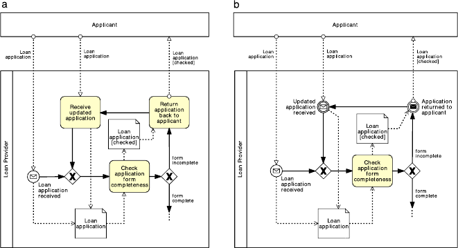
4.4 Handling Events 109
Fig. 4.11 Replacing activities that only send or receive messages (a) with message events (b)
do not really represent units of work, but rather the mechanical sending or receiving
of a message. An intermediate message event that receives a message is depicted as
a start message event but with a double border. If the intermediate event signals a
message being sent, the envelope is darkened.
Further, if the send activity is immediately followed by an untyped end event,
we can replace this with an end message event, since again, this activity is merely
used to send a message after which the process concludes. An end message event
is depicted as an end event marked with a darkened envelope. Beware that a start
message event is not an alternative notation for an untyped start event followed
by a receive activity: these two constructs are not interchangeable. In the former
case, process instances start upon the receipt of a specific message; in the latter
case, process instances may start at any time, after which the first activity requires a
message to be performed.
Question Typed or untyped event?
We suggest to specify the type of an event whenever this is known, since it will
help the reader better understand the process model.
Exercise 4.6 Is there any other activity in the loan assessment model of Solution 3.7
that can be replaced by a message event?
In BPMN, events come in two flavors based on the filling of their marker.
A marker with no fill, like that on the start message event, denotes a catching event,
i.e. an event that catches a trigger, typically originating from outside the process.
A marker with a dark fill like that on the end message event denotes a throwing

110 4 Advanced Process Modeling
Fig. 4.12 Using timer events to drive the various activities of a business process
event, i.e. an event that throws a trigger from within the process. An intermediate
message event has both flavors since it can be used both as a catching event (the
message is received from another pool) or as a throwing event (the message is sent
to another pool).
4.4.2 Temporal Events
Besides the message event, there are other triggers that can be specified for a start
event. One worth of notice is the timer event. This event type indicates that process
instances start upon the occurrence of a specific temporal event, e.g. every Friday
morning, every working day of the month, every morning at 7am.
A timer event may also be used as intermediate event, to model a temporal inter-
val that needs to elapse before the process instance can proceed. To indicate a timer
event, we mark the event symbol with a light watch inside the circle. Timer events
are catching events only since a timer is a trigger outside the control of the process.
In other words, the process does not generate the timer, but rather reacts to this.
Example 4.3 Let us consider the following process at a small claims tribunal.
In a small claims tribunal, callovers occur once a month, to set down the matter for the
upcoming trials. The process for setting up a callover starts three weeks prior to the callover
day, with the preparation of the callover list containing information such as contact details of
the involved parties and estimated hearing date. One week prior to the callover, the involved
parties are contacted to determine if they are all ready to go to trial. If this is the case, the
callover is set, otherwise it is deferred to the next available slot. Finally, on the callover day,
the callover material is prepared and the callover is held.
This process is driven by three temporal events: it starts three weeks prior to
the callover date, continues one week prior to the callover date, and concludes on
the day of the callover. To model these temporal events we need one start and
two intermediate timer events, as shown in Fig. 4.12. Let us see how this pro-
cess works from a token semantics point of view. A token capturing a new in-
stance is generated every time it is three weeks prior to the callover date (we
assume this date has been scheduled by another process). Once the first activity
4.4 Handling Events 111
“Prepare callover list” has been completed, the token is sent through the incom-
ing arc of the following intermediate timer event, namely “1 week prior to callover
day”. The event thus becomes enabled. The token remains trapped in the incom-
ing arc of this event until the temporal event itself occurs, i.e. only when it is one
week prior to the callover day. Once this is the case, the token instantaneously tra-
verses the event symbol and moves to the outgoing arc. This is why events are
said to be instantaneous, since they cannot retain tokens as opposed to activities,
which retain tokens for the duration of their execution (recall that activities con-
sume time).
Exercise 4.7 Model the billing process of an Internet Service Provider (ISP).
The ISP sends an invoice by email to the customer on the first working day of each month
(Day 1). On Day 7, the customer has the full outstanding amount automatically debited
from their bank account. If an automatic transaction fails for any reason, the customer
is notified on Day 8. On Day 9, the transaction that failed on Day 7 is re-attempted. If
it fails again, on Day 10 a late fee is charged to the customer’s bank account. At this
stage, the automatic payment is no longer attempted. On Day 14, the Internet service is
suspended until payment is received. If on Day 30 the payment is still outstanding, the
account is closed and a disconnection fee is applied. A debt-recovery procedure is then
started.
4.4.3 Racing Events
A typical scenario encountered when modeling processes with events is the one
where two external events race against one another. The first of the two events that
occurs determines the continuation of the process. For example, after an insurance
quote has been sent to a client, the client may reply either with an acceptance mes-
sage, in which case an insurance contract will be made, or with a rejection, in which
case the quote will be discarded.
This race between external events is captured by means of the event-based exclu-
sive (XOR) split. An event-based exclusive split is represented by a gateway marked
by an empty pentagon enclosed in a double-line circle. Figure 4.13 features an event-
based exclusive split. When the execution of the process arrives at this point (in
other words—when a token arrives at this gateway), the execution stops until ei-
ther the message event or the timer event occurs. Whichever event occurs first will
determine which way the execution will proceed. If the timer event occurs first, a
shipment status inquiry will be initiated and the execution flow will come back to
the event-based exclusive gateway. If the message signaling the freight delivery is
received first, the execution flow will proceed along the sequence flow that leads to
the AND-join.
The difference between the XOR-split that we saw in Chap. 3 and the event-based
XOR-split is that the former models an internal choice that is determined by the out-
come of a decision activity, whereas the latter models a choice that is determined

112 4 Advanced Process Modeling
Fig. 4.13 A race condition between an incoming message and a timer
by the process environment.
1
An internal choice is determined by the outcome of a
decision activity. Thus, the event-based XOR-split can only be followed by interme-
diate catching events like a timer or a message event, or by receiving activities. Since
the choice is delayed until an event happens, the event-based split is also known as
deferred choice. There is no event-based XOR-join, so the branches emanating from
an event-based split are merged with a normal XOR-join.
Exercise 4.8 Model the following process.
A restaurant chain submits a purchase order (PO) to replenish its warehouses every Thurs-
day. The restaurant chain’s procurement system expects to receive either a “PO Response”
or an error message. However, it may also happen that no response is received at all due to
system errors or due to delays in handling the PO on the supplier’s side. If no response is
received by Friday afternoon or if an error message is received, a purchasing officer at the
restaurant chain’s headquarters should be notified. Otherwise, the PO Response is processed
normally.
The event-based split can be used as the counterpart of an internal decision on
a collaborating party. For example, a choice made from within the Client pool to
send either an acceptance message or a rejection message to an Insurer, needs to be
matched by an event-driven decision on the insurer pool to react to the choice made
by the client. This example is illustrated in Fig. 4.14.
Event-based gateways can be used to avoid behavioral anomalies in the com-
munication between pools. Take for example the collaboration diagram between the
auctioning service and the seller in Fig. 4.15. This collaboration may deadlock if the
seller is already registered, as this party will wait for the account creation request
message which in that case will never arrive. To fix this issue, we need to allow the
seller to receive the creation confirmation message straightaway in case the seller is
already registered, as shown in Fig. 4.16.
1
Specifically, the XOR-split of Chap. 3 is called data-based XOR-split since the branch to take is
based on the evaluation of two or more conditions on data that are produced by a decision activity.

4.4 Handling Events 113
Fig. 4.14 Matching an internal choice in one party with an event-based choice in the other party
Fig. 4.15 An example of deadlocking collaboration between two pools

114 4 Advanced Process Modeling
Fig. 4.16 Using an event-based gateway to fix the deadlocking collaboration of Fig. 4.15
When connecting pools with each other via message flows, make sure you check
the order of these connections so as to avoid deadlocks. Recall, in particular, that
an internal decision in one party needs to be matched by an event-based decision in
the other party, and that an activity with an outgoing message flow will send that
message upon activity completion, whereas an activity with an incoming message
flow will wait for that message to start.
Exercise 4.9 Fix the collaboration diagram in Fig. 4.17.
Acknowledgement This exercise is partly inspired by: Niels Lohmann: “Correcting
Deadlocking Service Choreographies Using a Simulation-Based Graph Edit Dis-
tance”. LNCS 5240, Springer, 2008.
4.5 Handling Exceptions
Exceptions are events that deviate a process from its normal course, i.e. from what
is commonly known as the “sunny-day” scenario. These “rainy-day” situations hap-
pen frequently in reality, and as such they should be modeled when the objective is
to identify all possible causes of problems in a given process. Exceptions include
business faults like an exception due to an out-of-stock or discontinued product,
and technology faults like a database crash, a network outage or a program logic
violation. They deviate the normal process course since they cause the interruption

4.5 Handling Exceptions 115
Fig. 4.17 A collaboration diagram between a client, a travel agency and an airline
or abortion of the running process. For example, in case of an out-of-stock prod-
uct, an order-to-cash process may need to be interrupted to order the product from
a supplier, or aborted altogether if the product cannot be supplied within a given
timeframe.
4.5.1 Process Abortion
The simplest way of handling an exception is to abort the running process and signal
an improper process termination. This can be done by using an end terminate event,
as shown in Fig. 4.18. An end terminate event (depicted as an end event marked

116 4 Advanced Process Modeling
Fig. 4.18 Using a terminate event to signal improper process termination
with a full circle inside), causes the immediate cessation of the process instance at
its current level and for any sub-process.
In the example of Fig. 4.18—a variant of the home loan that we already saw in
Fig. 4.3—a home loan is rejected and the process is aborted if the applicant has
debts and/or low liability. From a token semantics, the terminate event destroys all
tokens in the process model and in any sub-process. In our example, this is needed
to avoid the process to deadlock at the AND-join, since a token may remain trapped
before the AND-join if there is high liability and debts or low liability and no debts.
Observe that if a terminate event is triggered from within a sub-process, it will
not cause the abortion of the parent process but only that of the sub-process, i.e. the
terminate event is only propagated downwards in a process hierarchy.
Exercise 4.10 Revise the examples presented so far in this chapter, by using the
terminate event appropriately.
4.5.2 Internal Exceptions
Instead of aborting the whole process, we can handle an exception by interrupting
the specific activity that has caused the exception. Next, we can start a recovery
procedure to bring the process back to a consistent state and continue its execution,
and if this is not possible, only then, abort the process altogether. BPMN provides
the error event to capture these types of scenario. An end error event is used to
interrupt the enclosing sub-process and throw an exception. This exception is then
caught by an intermediate catching error event which is attached to the boundary of
the same sub-process. In turn, this boundary event triggers the recovery procedure
through an outgoing branch which is called exception flow.

4.5 Handling Exceptions 117
Fig. 4.19 Error events model internal exceptions
The error event is depicted as an event with a lightning marker. Following the
BPMN conventions for throwing and catching events, the lightning is empty for the
catching intermediate event and full for the end throwing event.
An example of error events is shown in Fig. 4.19 in the context of our order ful-
fillment process. If there is an out of stock exception, the acquisition of raw materi-
als is interrupted and the recovery procedure is triggered, which in this case simply
consists of a task to notify the customer before aborting the process. In terms of
token semantics, upon throwing an end error event, all tokens are removed from
the enclosing sub-process (causing its interruption), and one token is sent through
the exception flow emanating from the boundary error event. There is no restriction
on the modeling elements we can put in the exception flow to model the recovery
procedure. Typically, we would complete the exception flow with an end terminate
event to abort the process, or wire this flow back to the normal sequence flow if the
exception has been properly handled.
4.5.3 External Exceptions
An exception may also be caused by an external event occurring during an activity.
For example, while checking the stock availability for the product in a purchase
order, the Seller may receive an order cancellation from the customer. Upon this
request, the Seller should interrupt the stock availability check and handle the order
cancellation. Scenarios like the above are called unsolicited exceptions since they
originate externally to the process. They can be captured by attaching a catching
intermediate message event to an activity’s boundary, as shown in Fig. 4.20.From
a token semantics, when the intermediate message event is triggered, the token is
removed from the enclosing activity, consequently causing the activity interruption,
and sent through the exception flow emanating from the boundary event, to perform
the recovery procedure.

118 4 Advanced Process Modeling
Fig. 4.20 Boundary events
catch external events that can
occur during an activity
Before using a boundary event we need to identify the scope within which the
process should be receptive of this event. For example, in the order fulfillment ex-
ample, order cancellation requests can only be handled during the execution of task
“Check stock availability”. Thus, the scope for being receptive to this event is made
up by this single task. Sometimes the scope should include multiple activities. In
these cases, we can encapsulate the interested activities into a sub-process and at-
tach the event to the sub-process’s boundary.
Exercise 4.11 Model the following routine for logging into an Internet bank ac-
count.
The routine for logging into an Internet bank account starts once the credentials entered
from the user have been retrieved. First, the username is validated. If the username is not
valid, the routine is interrupted and the invalid username is logged. If the username is valid,
the number of password trials is set to zero. Then the password is validated. If this is not
valid, the counter for the number of trials is incremented and if lower than three, the user
is asked to enter the password again, this time together with a CAPTCHA test to increase
the security level. If the number of failed attempts reaches three times, the routine is in-
terrupted and the account is frozen. Moreover, the username and password validation may
be interrupted should the validation server not be available. Similarly, the server to test the
CAPTCHA may not be available at the time of log in. In these cases, the procedure is inter-
rupted after notifying the user to try again later. At any time during the log in routine, the
customer may close the web-page, resulting in the interruption of the routine.
4.5.4 Activity Timeouts
Another type of exception is that provoked by the interruption of an activity which
is taking too long to complete. To model that an activity must be completed within
a given timeframe (e.g. an approval must be completed within 24 hours), we can
attach an intermediate timer event to the boundary of the activity: the timer is acti-
vated when the enclosing activity starts, and if it fires before the activity completes,
provokes the activity’s interruption. In other words, a timer event works as a timeout
when attached to an activity’s boundary.

4.5 Handling Exceptions 119
Fig. 4.21 Non-interrupting
boundary events catch
external events that occur
during an activity, and trigger
a parallel procedure without
interrupting the enclosing
activity
Exercise 4.12 Model the following process fragment.
Once a wholesale order has been confirmed, the supplier transmits this order to the car-
rier for the preparation of the transportation quote. In order to prepare the quote, the car-
rier needs to compute the route plan (including all track points that need to be traversed
during the travel) and estimate the trailer usage (e.g. whether it is a full track-load, half
track-load or a single package). By contract, wholesale orders have to be dispatched within
four days from the receipt of the order. This implies that transportation quotes have to be
prepared within 48 hours from the receipt of the order to remain within the terms of the
contract.
4.5.5 Non-interrupting Events and Complex Exceptions
There are situations where an external event occurring during an activity should just
trigger a procedure without interrupting the activity itself. For example, in the order
fulfillment process, the customer may send a request to update their details during
the stock availability check. The details should be updated in the customer database
without interrupting the stock check. In order to denote that the boundary event is
non-interrupting, we use a dashed double border, as shown in Fig. 4.21.
Exercise 4.13 Extend the process for assessing loan applications of Solution 3.7 as
follows.
An applicant who has decided not to combine their loan with a home insurance plan may
change their mind any time before the eligibility assessment has been completed. If a request
for adding an insurance plan is received during this period, the loan provider will simply
update the loan application with this request.
Non-interrupting events can be used to model more complex exception handling
scenarios. Consider again the example in Fig. 4.19 and assume that the customer
sends a request to cancel the order during the acquisition of raw materials. We catch
this request with a non-interrupting boundary message event, and first determine

120 4 Advanced Process Modeling
Fig. 4.22 Non-interrupting events can be used in combination with signal events to model com-
plex exception handling scenarios
the penalty that the customer will need to incur based on the raw materials that
have already been ordered. We forward this information to the customer who then
may decide within 48 hours to either stop the cancellation, in which case nothing
is done, or go on with it (see Fig. 4.22). In the latter case, we throw an end signal
event. This event, depicted with a triangle marker, broadcasts a signal defined by
the event’s label, which can be caught by all catching signal events bearing the
same label. In our case, we throw an “Order canceled” signal and catch this with a
matching intermediate signal event on the boundary of the sub-process for acquiring
raw materials. This event causes the enclosing sub-process to be interrupted and
then triggers a recovery procedure to charge the customer, after which the process is
aborted. We observe that in this scenario the activity interruption is triggered from
within the process, but outside the activity itself.
Observe that the signal event is different from the message event, since it has
a source but no specific target, whilst a message has both a specific source and a
specific target. Like messages, signals may also originate from a process modeled
in a separate diagram.

4.5 Handling Exceptions 121
Fig. 4.23 Event sub-processes can be used in place of boundary events, and to catch events thrown
from outside the scope of a particular sub-process
4.5.6 Interlude: Event Sub-processes
An alternative notation to boundary events is the event sub-process. An event sub-
process is started by the event which would otherwise be attached to the boundary
of an activity, and encloses the procedure that would be triggered by the boundary
event. An important difference with boundary events is that event sub-processes do
not need to refer to a specific activity, but can model events that occur during the
execution of the whole process. For example, any time during the order fulfillment
process the customer may send an inquiry about the order status. To handle this
request, which is not specific to a particular activity of this process, we can use an
event sub-process as shown in Fig. 4.23.
The event sub-process is depicted within a dotted rectangle with rounded corners
which is placed into an expanded sub-process or into the top-level process. Similar
to boundary events, an event sub-process may or may not interrupt the enclosing
process depending on whether its start event is interrupting or not. If its start event
is non-interrupting, this is depicted with a dashed (single) border.
All syntactical rules for a sub-process apply to the event sub-process, except for
boundary events, which cannot be defined on event sub-processes. For example, the
event sub-process can also be represented as a collapsed sub-process. In this case,
the start event is depicted on the top-left corner of the collapsed event sub-process
rectangle to indicate how this event sub-process is triggered.
Question Event sub-processes or boundary events?
Event sub-processes are self-contained, meaning that they must conclude with
an end event. This has the disadvantage that the procedure captured inside an event
122 4 Advanced Process Modeling
sub-process cannot be wired back to the rest of the sequence flow. The advantage
is that an event sub-process can also be defined as a global process model, and thus
be reused in other process models of the same organization. Another advantage is
that event sub-processes can be defined at the level of an entire process whereas
boundary events must refer to a specific activity. Thus, we suggest to use event
sub-processes when the event that needs to be handled may occur during the en-
tire process, or when we need to capture a reusable procedure. For all other cases,
boundary events are more appropriate since the procedure triggered by these events
can be wired back to the rest of the flow.
Exercise 4.14 Model the following business process for reimbursing expenses.
After an Expense report is received from an employee, the employee is notified of the
receipt of the report. Next, a new account must be created if the employee does not already
have one. The report is then reviewed for automatic approval. Amounts under €1,000 are
automatically approved while amounts equal to or over €1,000 require manual approval.
In case of rejection, the employee must receive a Rejection notice by email. In case of
approval, the reimbursement is deposited directly to the employee’s bank account. At any
time during the review, the employee can send a Request for amount rectification. In that
case the rectification is registered and the report needs to be reviewed again. Moreover, if
the report is not handled within 30 days, the process is stopped and the employee receives
a Cancelation notice email so that he can re-submit the expense report from scratch.
4.5.7 Activity Compensation
As part of a recovery procedure, we may need to undo one or more steps that have
already been completed, due to an exception that occurred in the enclosing sub-
process. In fact, the results of these steps, and possibly their side effects, may no
longer be desired and for this reason they should be reversed. This operation is
called compensation and tries to restore the process to a business state close to the
one before starting the sub-process that was interrupted.
Let us delve into the sub-process for shipment and invoice handling of the order
fulfillment example and assume that also this activity can be interrupted upon the
receipt of an order cancellation request (see Fig. 4.24). After communicating the
cancellation penalty to the customer, we need to revert the effects of the shipment
and of the payment. Specifically, if the shipment has already been made, we need to
handle the product return, whereas if the payment has already been made, we need to
reimburse the Customer. These compensations can be modeled via a compensation
handler. A compensation handler is made up of a throwing compensate event (an
event marked with a rewind symbol), a catching intermediate compensate event and
a compensation activity. The throwing compensate event is used inside the recovery
procedure of an exception to start the compensation, and can either be an interme-
diate or an end event (in the latter case, the recovery procedure concludes with the
compensation). The catching intermediate compensation event is attached to those
activities that need to be compensated—in our example “Ship product” and “Re-
ceive payment”. These boundary events catch the compensation request and trigger

4.5 Handling Exceptions 123
Fig. 4.24 Compensating for the shipment and for the payment
a compensation activity specific to the activity to be compensated. For example the
compensation activity for “Receive payment” is “Reimburse customer”. The bound-
ary event is connected to the compensation activity via a dotted arrow with an open
arrowhead, called compensation association (whose notation is the same as that of
the data association). This activity is marked with the compensate symbol to indi-
cate its purpose, and must not have any outgoing flow: in case the compensation
procedure is complex, this activity can be a sub-process.
Compensation is only effective if the attached activity has completed. Once all
activities that could be compensated are compensated, the process resumes from af-
ter the throwing compensation event, unless this is an end event. If the compensation
is for the entire process, we can use an event sub-process with a start compensate
event in place of the boundary event.
In this section we have seen various ways to handle exceptions in business pro-
cess, from simple process abortion to complex exception handling. Before adding
exceptions it is important to understand the sunny-day scenario well. So start by
modeling that. Then think of all possible situations that can go wrong. For each of
these exceptions, identify what type of exception handling mechanism needs to be
used. First, determine the cause of the exception: internal or external. Next, decide
if aborting the process is enough, or if a recovery procedure needs to be triggered.
Finally, evaluate whether the interrupted activity needs to be compensated as part of
the recovery procedure.

124 4 Advanced Process Modeling
Fig. 4.25 A replenishment
order is triggered every time
the stock levels drop below a
threshold
Exercise 4.15 Modify the model that you created in Exercise 4.14 as follows.
If the report is not handled within 30 days, the process is stopped, the employee receives a
cancellation notice email and must re-submit the expense report. However, if the reimburse-
ment for the employee’s expenses had already been made, a money recall needs to be made,
to get the money back from the employee, before sending the cancellation notice email.
4.6 Processes and Business Rules
A business rule implements an organizational policy or practice. For example, in
an online shop, platinum customers have a 20 % discount for each purchase above
€250. Business rules can appear in different forms in a process model. We have
seen them modeled in a decision activity and in the condition of a flow coming out
of an (X)OR-split (see Exercise 3.5 for some examples). A third option is to use
a dedicated BPMN event called conditional event. A conditional event causes the
activation of its outgoing flow when the respective business rule is fulfilled. Condi-
tional events, identified by a lined page marker, can be used as start or intermediate
catching events, including after an event-based gateway or attached to an activity’s
boundary. An example of conditional event is shown in Fig. 4.25.
The difference between an intermediate conditional event and a condition on a
flow is that the latter is only tested once, and if it is not satisfied the corresponding
flow is not taken (another flow or the default flow will be taken instead). The condi-
tional event, on the other hand, is tested until the associated rule is satisfied. In other
words, the token remains trapped before the event until the rule is satisfied.
In the example of Fig. 4.25, observe the use of the error event on the boundary of
a multi-instance activity. This event only interrupts the activity instance that refers
to the particular product being discontinued, i.e. the instance from which the error
event is thrown. All other interrupting boundary events, i.e. message, timer, signal
and conditional, interrupt all instances of a multi-instance activity.
Exercise 4.16 Model the following business process snippet.
4.7 Process Choreographies 125
In a stock exchange, stock price variations are continuously monitored during the day. A day
starts when the opening bell rings and concludes when the closing bell rings. Between the
two bells, every time the stock price changes by more than 10 %, the entity of the change is
first determined. Next, if the change is high, a “high stock price” alert is sent, otherwise a
“low stock price” alert is sent.
4.7 Process Choreographies
Sometimes it might be hard to frame a business collaboration between two or more
parties, e.g. two organizations, by working directly at the level of the collaboration
diagram. First, the collaboration diagram is typically too low-level and if the terms
of the interactions between the two parties are not clear yet, it might be confusing to
mix communication aspects with internal activities. Second, a party may not be will-
ing to expose their internal activities to other parties (e.g. the logic behind a claim
approval should remain private). Thus, it might be opportune to first focus on the
interactions that have to occur among all involved parties, and on the order in which
these interactions can take place. In BPMN, this information is captured by a chore-
ography diagram. A choreography diagram is the process model of the interactions
occurring between two or more parties. This high-level view on a collaboration acts
as a contract among all involved parties. Once this contract has been crafted, each
party can take it and refine it into their private processes, or alternatively, all parties
can work together to refine the choreography into a collaboration diagram.
Figure 4.26 shows the choreography for the order fulfillment collaboration of
Fig. 4.9. As we can see, a choreography is indeed a process model: it is started by
one or more start events and concluded by one or more end events, activities are con-
nected via sequence flows and gateways are used for branching and merging. The
key characteristic is, however, that an activity represents an interaction between two
parties, rather than a unit of work. An interaction can be one-way (one message is
exchanged) or two-way (a message is followed by a return message in the opposite
direction). Each interaction has an initiator or sender (the party sending the mes-
sage), and a recipient or receiver (the party receiving the message, who may reply
with a return message). For example, the first activity of Fig. 4.26, “Submit pur-
chase order” takes place between the Customer, who sends the purchase order, and
the Seller, who receives it.
A choreography activity is depicted as a box with rounded corners where two
bands, one at the top, the other at the bottom of the box, represent the two parties
involved in the interaction captured by the activity. A light band is used for the
initiator whilst a darkened band is used for the recipient. The position of each band
with respect to the box is left to the modeler, so long as the two bands are on opposite
sides. An envelope attached to a band via a dashed line represents the message sent
by that party. This envelop is darkened if it is the return message of a two-way
interaction.
A precedence relation between two interactions can only be established if the
initiator of the second interaction is involved in the preceding interaction (either as

126 4 Advanced Process Modeling
Fig. 4.26 The choreography diagram for the collaboration diagram in Fig. 4.9
a sender or as a receiver), except for the first interaction. In this way the sender of
the second interaction ‘knows’ when this can take place. On the other hand, if there
are no order dependencies between two or more interactions, we can link these
interactions via an AND-split, as shown in Fig. 4.26. Make sure, however, that the
sender of each interaction following the split is involved in the interaction preceding
the split.
An (X)OR-split models the outcomes of a an internal decision that is taken by one
party. This imposes that the data upon which the decision is taken are made available
to that party via an interaction prior to the split. In our example, the data required by
the XOR-split are extrapolated from the purchase order, which is sent to the seller
in the interaction just before the split. Furthermore, all interactions immediately
following the split must be initiated by the party who took the decision. In our
example, these are done by the seller. In fact, it makes no sense that a decision taken
by one party results in an interaction initiated by another party—the latter would not
be able to know the results of the decision at that stage.
The event-based XOR-split is used when the data to make a choice are not ex-
posed through an interaction before the split. Thus, the parties not involved in the
decision will only know about this with the receipt of a message. This imposes that
the interactions following an event-based split must either have the same sender or
the same receiver. For example, we use an event-based split to model a situation
where an applicant waits for a confirmation message that may either arrive from
a broker or directly from the insurer (the decision of which party to interact with

4.7 Process Choreographies 127
Fig. 4.27 The choreography diagram between a seller, a customer and a carrier
the applicant is taken by the broker together with the insurer). Figure 4.27 shows
another example: here a seller waits for one of three possible messages from a cus-
tomer, representing three different types of complaint. The decision is taken by the
customer and the seller is not aware of this until the specific complain is received.
The interactions following an event-based split can be constrained by a timer. In this
example, if the seller does not receive any message after five days, they will trigger
an interaction to invoice the customer. In this case, all parties in the interactions fol-
lowing the split must be involved in the interaction preceding the split in order to be
aware of the timer.
Exercise 4.17 The choreography below illustrates the interactions that may occur
among a seller, a customer and a carrier after the freight has been delivered by the
carrier to the client. Use this diagram as a template to build the corresponding col-
laboration diagram. Observe the use of the terminate event in this example. In a
choreography this event can only be used to denote a negative outcome and not to
forcefully terminate the choreography, since the parties not involved in the interac-
tion preceding the terminate event would not know that the terminate event has been
reached.
128 4 Advanced Process Modeling
Complex interactions involving more than one business party are modeled via
a sub-choreography activity. This activity is represented with the plus symbol (as
a sub-process) and may have multiple bands representing all roles involved. For
example, the “Handle damage claim” interaction in Fig. 4.27 occurs between the
seller, the carrier and the customer. The messages involved in a sub-choreography
are only visible when expanding the content of the sub-choreography where also
their order becomes apparent.
Artifacts cannot be explicitly expressed in a choreography via data objects or data
stores. This is because a choreography does not have a central control mechanism
to maintain data.
Exercise 4.18 Model the choreography and collaboration diagrams for the follow-
ing mortgage application process at BestLoans.
The mortgage application process starts with the receipt of a mortgage application from a
client. When an application is sent in by the client to the broker, the broker may either deal
with the application themselves, if the amount of the mortgage loan is within the mandate
the broker has been given by BestLoans, or forward the application to BestLoans. If the
broker deals with the application themselves, this results in either a rejection or an approval
letter being sent back to the client. If the broker sends an approval letter, then it forwards the
details of this application to BestLoans so that from there on the client can interact directly
with BestLoans for the sake of disbursing the loan. In this case, BestLoans registers the
application and sends an acknowledgment to the client.
The broker can only handle a given number of clients at a time. If the broker is not able to
reply within one week, the client must contact BestLoans directly. In this case, a reduction
on the interest rate is applied should the application be approved.
If BestLoans deals with the application directly, its mortgage department checks the credit
of the client with the Bureau of Credit Registration. Moreover, if the loan amount is more
than 90 % of the total cost of the house being purchased by the client, the mortgage depart-
ment must request a mortgage insurance offer from the insurance department. After these
interactions BestLoans either sends an approval letter or a rejection to the broker, which the
broker then forwards to the client (this interaction may also happen directly between the
mortgage department and the client if no broker is involved).
After an approval letter has been submitted to the client, the client may either accept or reject
the offer by notifying this directly to the mortgage department. If the mortgage department
receives an acceptance notification, it writes a deed and sends it to an external notary for
signature. The notary sends a copy of the signed deed to the mortgage department. Next, the
insurance department starts an insurance contract for the mortgage. Finally, the mortgage
department submits a disbursement request to the financial department. When this request
has been handled, the financial department notifies the client directly.
Any time during the application process, the client may inquire about the status of their
application with the mortgage department or with the broker, depending on which entity is
dealing with the client. Moreover, the client may request the cancellation of the application.
In this case the mortgage department or the broker computes the application processing
fees, which depend on how far the application process is, and communicates these to the
client. The client may reply within two days with a cancellation confirmation, in which
case the process is canceled, or with a cancellation withdrawal, in which case the process
continues. If the process has to be canceled, BestLoans may need to first recall the loan (if
the disbursement has been done), then annul the insurance contract (if an insurance contract
has been drawn) and finally annul the deed (if a deed has been drawn).
4.8 Recap 129
4.8 Recap
This chapter provided us with the means to model complex business processes. We
first learned how to structure complex process models in hierarchical levels via sub-
process activities. Sub-processes represent activities that can be broken down in a
number of internal steps, as compared to tasks, which capture single units of work.
An interesting aspect of sub-processes is that they can be collapsed to hide details.
We also discussed how to maximize reuse by defining global sub-processes within a
process model collection, and invoking them via call activities. A global sub-process
is modeled once and shared by different process models in a repository.
We then expanded on the topic of rework and repetition. We illustrated how struc-
tured loops can be modeled using a loop activity. Furthermore, we presented the
multi-instance activity as a way to model an activity that needs to be executed mul-
tiple times without knowing the number of occurrences beforehand. Further, we
saw how the concept of multi-instantiation can be related to data collections and ex-
tended to pools. We also discussed ad-hoc sub-processes for capturing unstructured
repetition.
Next, we expanded on various types of event. We explained the difference be-
tween catching and throwing events and distinguished between start, end and inter-
mediate events. We saw how message exchange between pools can be framed by
message events, and how timer events can be used to model temporal triggers to the
process or delays during the process. We then showed how to capture racing condi-
tions between events external to the process, using an event-based split followed by
intermediate catching events.
Afterwards, we showed how to handle exceptions. Exceptions are situations that
deviate the process from its normal course, due to technology or business faults.
The simplest way to react to an exception is to abort the process via a terminate
end event. Exceptions can be handled by using a catching intermediate event on the
boundary of an activity. If the event is caught during the activity’s execution, the
activity is interrupted and a recovery procedure may be launched. Another type of
exception is the activity timeout. This occurs when an activity does not complete
within a given timeframe. A boundary event can also be configured not to interrupt
the attached activity. In this case the event is called non-interrupting. These events
are convenient to model procedures that have to be launched in parallel to an activ-
ity’s execution, when an event occurs. Related to exception handling is the notion of
activity compensation. Compensation is required to revert the effects of an activity
that has been completed, if these effects are no longer desired due to an exception
that has occurred.
We then saw how business rules can be defined in process models via conditional
events. A conditional event, available as a start and catching intermediate event, al-
lows a process instance to start, or progress, only when the corresponding (boolean)
business rule evaluates to true.
We concluded this chapter on advanced process modeling by introducing chore-
ography diagrams. A choreography diagram models the interactions that happen be-
tween the various business parties partaking in a business process. Each activity in

130 4 Advanced Process Modeling
the choreography captures an interaction between a sender and a receiver. To estab-
lish an order dependency between two interactions, the sender of the second activity
must be involved in the first one, otherwise this party will not be able to determine
when to send the message pertaining to the second interaction. We also discussed the
rules for using gateways in a choreography where a decision is made by a specific
party based on data or events. Sub-choreographies can be used to model complex
interactions involving more than two parties, in a similar vein to sub-processes in a
collaboration.
4.9 Solutions to Exercises
Solution 4.1
Solution 4.2 Possible sub-processes are “Request purchase”, “Issue purchase or-
der”, “Receive goods” and “Handle invoice”. Of these, “Handle invoice” could be
shared with other procure-to-pay processes of the same company, e.g. with that de-
scribed in Example 1.1 for BuildIT. The first three sub-processes are internal to
this procure-to-pay process, because they are specific to the enterprise system that
supports this process.
Solution 4.3
1. In Exercise 3.9 the repetition block goes from activity “Record claim” to activity
“Review claim rejection”. The entry point to the cycle is the input arc of activ-
ity “Record claim”; the exit points are arcs “claim to be accepted” and “claim
rejection accepted”, the former being inside the repetition block.
2. In Solution 3.4 the repetition block is made up of activities “Check application
form completeness”, “Return application back to applicant” and “Receive up-
dated application”. The entry point to the cycle is the outgoing arc of the XOR-
split, while the exit point is the arc “form complete” which is inside the repetition
block. To model this cycle with a loop activity, we need to repeat activity “Check
application form completeness” outside the loop activity, as shown below.

4.9 Solutions to Exercises 131
In this case using a loop activity is still advantageous, since we reduce the size
of the original model if we collapse the sub-process.
Solution 4.4

132 4 Advanced Process Modeling
Solution 4.5

4.9 Solutions to Exercises 133
Solution 4.6 Activity “Send acceptance pack” can be replaced by an intermediate
send message event; activities “Notify cancelation” and “Notify approval” can each
be replaced by an end message event, thus removing the last XOR-join and the un-
typed end event altogether. Note that activity “Send home insurance quote” cannot
be replaced by a message event since it subsumes the preparation of the quote. In
fact, a more appropriate label for this activity would be “Prepare home insurance
quote”. Similarly, we cannot get rid of activity “Reject application” as this activity
changes the status of the application before sending the latter out.
Solution 4.7
Solution 4.8

134 4 Advanced Process Modeling
Solution 4.9
Solution 4.10 The following end events should be terminate events: Fig. 4.12—
“callover deferred”, Fig. 4.14—“Quote rejected” in the Client and Insurer pools,
Fig. 4.18—“Offer rejected” in the Customer pool, “Offer canceled” in the Travel
Agency pool and “Payment refused” in the Airline pool.

4.9 Solutions to Exercises 135
Solution 4.11
Solution 4.12

136 4 Advanced Process Modeling
Solution 4.13
Observe that in the “Assess application” sub-process, the Loan application can have
two possible states: “checked” or “unchecked”. In order to use the Loan application
in any such state as input of activity “Add insurance request to loan application”, we
do not specify any state for this data object in the above model.

4.9 Solutions to Exercises 137
Solution 4.14

138 4 Advanced Process Modeling
Solution 4.15

4.9 Solutions to Exercises 139
Solution 4.16
In this solution we did not use a boundary event to stop the sub-process for moni-
toring stock price changes since this way, the sub-process would only stop because
of an exception. Rather, we used the loop condition to allow the sub-process to
complete normally, i.e. without being interrupted.

140 4 Advanced Process Modeling
Solution 4.17
Fig. 4.28 Collaboration diagram—part 1/2 (Freight shipment fragment)

4.9 Solutions to Exercises 141
Fig. 4.29 Collaboration diagram—part 2/2 (Merchandise return handling fragment)
In Solution 4.17 we used the link event to lay the diagram over two pages, since
the model was too large to fit in one page. The link event does not have any se-
mantics: it is purely a notational expedient to break a diagram over multiple pages.
An intermediate throwing link event (marked with a full arrow) breaks the process
flow and provides a link to the diagram where the flow continues; an intermediate
catching link event (marked with an empty arrow) resumes the flow and indicates
the diagram where this flow is resumed from.

142 4 Advanced Process Modeling
Solution 4.18
Fig. 4.30 Choreography diagram—part 1/2

4.9 Solutions to Exercises 143
Fig. 4.31 Choreography diagram—part 2/2

144 4 Advanced Process Modeling
Fig. 4.32 Collaboration diagram—part 1/3 (Loan establishment fragment)

4.9 Solutions to Exercises 145
Fig. 4.33 Collaboration diagram—part 2/3 (Loan disbursement fragment)

146 4 Advanced Process Modeling
Fig. 4.34 Collaboration diagram—part 3/3 (sub-processes)
4.10 Further Exercises
Exercise 4.19
1. Model the prescription fulfillment process described in Exercise 1.6. Use sub-
processes where required, and nest them appropriately.
2. Is there any sub-process that can potentially be shared with other business pro-
cesses of the same pharmacy, or of other pharmacies?
4.10 Further Exercises 147
Exercise 4.20 Model the business process described in Exercise 3.12 using a loop
activity.
Exercise 4.21
1. What is the limitation of using a loop activity to model repetition instead of using
unstructured cycles?
2. What is the requirement for a sub-process to be used as a loop activity?
3. Model the procure-to-pay process described in Example 1.1.
Hint Use the model in Fig. 1.6 as a starting point for item (3).
Exercise 4.22 Model the following business process.
Mail from the party is collected on a daily basis by the mail processing unit. Within this
unit, the mail clerk sorts the unopened mail into the various business areas. The mail is then
distributed. When the mail is received by the registry, it is opened and sorted into groups for
distribution, and thus registered in a mail register. Afterwards, the assistant registry manager
within the registry performs a quality check. If the mail is not compliant, a list of requisi-
tions explaining the reasons for rejection is compiled and sent back to the party. Otherwise,
the matter details are captured and provided to the cashier, who takes the applicable fees
attached to the mail. At this point, the assistant registry manager puts the receipt and copied
documents into an envelope and posts it to the party. Meantime, the cashier captures the
party details and prints the physical court file.
Exercise 4.23 Model the following process for selecting Nobel prize laureates for
chemistry.
September: nomination forms are sent out. The Nobel committee sends out confidential
forms to around 3,000 people—selected professors at universities around the world, No-
bel laureates in physics and chemistry, and members of the Royal Swedish Academy of
Sciences, among others.
February: deadline for submission. The completed nomination forms must reach the No-
bel Committee no later than 31 January of the following year. The committee screens the
nominations and selects the preliminary candidates. About 250–350 names are nominated
as several nominators often submit the same name.
March–May: consultation with experts. The Nobel committee sends the list of the pre-
liminary candidates to specially appointed experts for their assessment of the work of the
candidates.
June–August: writing of the report. The Nobel committee puts together the report with
recommendations to be submitted to the Academy. The report is signed by all members of
the committee.
September: committee submits recommendations. The Nobel committee submits its report
with recommendations on the final candidates to the members of the Academy. The report
is discussed at two meetings of the chemistry section of the Academy.
October: Nobel laureates are chosen. In early October, the Academy selects the Nobel lau-
reates in chemistry through a majority vote. The decision is final and without appeal. The
names of the Nobel laureates are then announced.
December: Nobel laureates receive their prize. The Nobel prize award ceremony takes place
on 10 December in Stockholm, where the Nobel laureates receive their Nobel prize, which
consists of a Nobel medal and diploma, and a document confirming the prize amount.

148 4 Advanced Process Modeling
Acknowledgement This exercise is taken from “Nomination and Selection of Chem-
istry Laureates”, Nobelprize.org. 29 Feb 2012 (http://www.nobelprize.org/nobel_
prizes/chemistry/nomination).
Exercise 4.24
1. What is the difference between throwing and catching events?
2. What is the meaning of an event attached to an activity’s boundary and what
events can be attached to an activity’s boundary?
3. What is the difference between the untyped end event and the terminate end
event.
Exercise 4.25 What is wrong with the following model?
Exercise 4.26 Extend the billing process model seen in Exercise 4.7 as follows.
Any time after the first transaction has failed, the customer may pay the invoice directly to
the ISP. If so, the billing process is interrupted and the payment is registered. This direct
payment must also cover the late fees, based on the number of days passed since Day 7 (the
last day to avoid incurring late fees). If the direct payment does not include late fees, the
ISP sends a notification to the customer that the fees will be charged in the next invoice,
before concluding the process.

4.10 Further Exercises 149
Exercise 4.27 What is wrong with the following model?
Exercise 4.28 Model the following business process at a supplier.
After a supplier notifies a retailer of the approval of a purchase order, the supplier can either
receive an order confirmation, an order change or an order cancellation from the retailer. It
may happen that no response is received at all. If no response is received after 48 hours, or if
an order cancellation is received, the supplier will cancel the order. If an order confirmation
is received within 48 hours, the supplier will process the order normally. If an order change
is received within 48 hours, the supplier will update the order and ask again the retailer for
confirmation. The retailer is allowed to change an order at most three times. Afterwards, the
supplier will automatically cancel the order.
Exercise 4.29 Revise the model in Exercise 3.9 by using the terminate event.
Exercise 4.30 Model the following business process.
When a claim is received, it is first registered. After registration, the claim is classified
leading to two possible outcomes: simple or complex. If the claim is simple, the insurance
policy is checked. For complex claims, both the policy and the damage are checked inde-
pendently. A possible outcome of the policy check is that the claim is invalid. In this case,
any processing is canceled and a letter is sent to the customer. In the case of a complex
claim, this implies that the damage checking is canceled if it has not been completed yet.
After the check(s), an assessment is performed which may lead to two possible outcomes:
positive or negative. If the assessment is positive, the garage is phoned to authorize the
repairs and the payment is scheduled (in this order). In any case (whether the outcome is
positive or negative), a letter is sent to the customer and the process ends. At any moment
after the registration and before the end of the process, the customer may call to modify the
details of the claim. If a modification occurs before the payment is scheduled, the claim is
classified again (simple or complex) and the process is repeated. If a request to modify the
claim is received after the payment is scheduled, the request is rejected.
Exercise 4.31 Model the following business process.
150 4 Advanced Process Modeling
An order handling process starts when an order is received. The order is first registered.
If the current date is not a working day, the process waits until the following working day
before proceeding. Otherwise, an availability check is performed and a purchase order re-
sponse is sent back to the customer. If any item is not available, any processing related to
the order must be stopped. Thereafter, the client needs to be notified that the purchase order
cannot be further processed. Anytime during the process, the customer may send a purchase
order cancel request. When such a request is received, the purchase order handling process
is interrupted and the cancellation is processed. The customer may also send a “Customer
address change request” during the order handling process. When such a request is received,
it is just registered, without further action.
Exercise 4.32
1. What is the difference between a collaboration and a choreography diagram?
What are the respective modeling objectives?
2. Model the choreography diagram for the collaboration diagram that you modeled
in Exercise 3.7.
Exercise 4.33 Model the choreography and collaboration diagrams for the follow-
ing business process for electronic land development applications.
The Smart Electronic Development Assessment System (Smart eDA) is a Queensland Gov-
ernment initiative aimed to provide an intuitive service for preparing, lodging and assess-
ing land development applications. The land development business process starts with the
receipt of a land development application from an applicant. Upon the receipt of a land
development application, the assessment manager interacts with the cadastre to retrieve ge-
ographical information on the designated development area. This information is used to
get an initial validation of the development proposal from the city council. If the plan is
valid, the assessment manager sends the applicant a quote of the costs that will incur to
process the application. These costs depend on the type of development plan (for residential
or commercial purposes), and on the permit/license that will be required for the plan to be
approved. If the applicant accepts the quote, the assessment can start.
The assessment consists of a detailed analysis of the development plan. First, the assessment
manager interacts with the Department of Main Roads (DMR) to check for conflicts with
planned road development works. If there are conflicts, the application cannot proceed and
must be rejected. In this case, the applicant is notified by the assessment manager. The
applicant may wish to modify the development plan and re-submit it for assessment. In this
case, the process is resumed from where it was interrupted.
If the development plan includes modifications to the natural environment, the assessment
manager needs to request a land alteration permit to the Department of Natural Resources
and Water (NRW). If the plan is for commercial purposes, additional fees will be applied
to obtain this permit. Once the permit is granted, this is sent by NRW directly to the ap-
plicant. Likewise, if the designated development area is regulated by special environment
protection laws, the assessment manager needs to request an environmental license to the
Environmental Protection Agency (EPA). Similarly, once the license is granted, this is sent
by EPA directly to the applicant. Once the required permit and/or license have been ob-
tained, the assessment manager notifies the Applicant of the final approval.
At any time during this process, the applicant can track the progress of their application by
interacting directly with the assessment manager.
Assessment manager, cadastre, DMR, NRW and EPA are all Queensland Government enti-
ties. In particular, NRW and EPA are part of the Department of Environment and Resource
Management within the Queensland Government.
4.10 Further Exercises 151
Exercise 4.34 Model the choreography and collaboration diagrams for the follow-
ing business process for ordering maintenance activities at Sparks.
The ordering business process starts with the receipt of a request for work order from a
customer. Upon the receipt of this request, the ordering department of Sparks estimates
the expected usage of supplies, parts and labor and prepares a quote with the estimated
total cost for the maintenance activity. If the customer’s vehicle is insured, the ordering
department interacts with the insurance department to retrieve the details of the customer’s
insurance plan so that these can be attached to the quote. The ordering department then
sends the quote to the customer, who can either accept or reject the quote by notifying
the ordering department within five days. If the customer accepts the quote, the ordering
department contacts the warehouse department to check if the required parts are in stock
before scheduling an appointment with the customer. If some parts are not in stock, the
ordering department orders the required parts by interacting with a certified reseller and
waits for an order confirmation from the reseller, to be received within three days. If it is
not received, the order department orders the parts again from a second reseller. If no reply
is received from the second reseller too, the order department notifies the customer that the
parts are not available and the process terminates. If the required parts are in stock or have
been ordered, the ordering department interacts with an external garage to book a suitably
equipped service bay and a suitably qualified mechanic to perform the work. A confirmation
of the appointment is then sent by the garage to the order department which forwards the
confirmation to the customer. The customer has one week to pay Sparks, otherwise the
ordering department cancels the work order by sending a cancellation notice to both the
service bay and the mechanic that have been booked for this order. If the customer pays in
time, the work order is performed.
Exercise 4.35 Model the choreography and collaboration diagrams for the follow-
ing business process at MetalWorks. Keep in mind that the purpose of this BPMN
diagram is to serve as a means of communication between the business stakeholders
and the IT team who has to build a software system to automate this process.
A build-to-order (BTO) process, also known as make-to-order process, is an “order-to-cash”
process where the products to be sold are manufactured on the basis of a confirmed purchase
order. In other words, the manufacturer does not maintain any ready-to-ship products in their
stock. Instead, the products are manufactured on demand when the customer orders them.
This approach is used in the context of customized products, such as metallurgical products,
where customers often submit orders for products with very specific requirements.
We consider a BTO process at a company called MetalWorks. The process starts when
MetalWorks receives a purchase order (PO) from one of its customers. This PO is called the
“customer PO”. The customer PO may contain one or multiple line items. Each line item
refers to a different product.
Upon receiving a customer PO, a sales officer checks the PO to determine if all the line
items in the order can be produced within the timeframes indicated in the PO. As a result
of this check, the sales officer may either confirm the customer PO or ask the customer
to revise the terms of the PO (for example: change the delivery date to a later date). In
some extreme cases, the sales officer may reject the PO, but this happens very rarely. If
the customer is asked to revise the PO, the BTO process will be put in “stand-by” until the
customer submits a revised PO. The sales officer will then check the revised PO and either
accept it, reject it, or ask again the customer to make further changes.
Once a PO is confirmed, the sales officer creates one “work order” for each line item in the
customer PO. In other words, one customer PO gives place to multiple work orders (one
per line item). The work order is a document that allows employees at MetalWorks to keep
track of the manufacturing of a product requested by a customer.
152 4 Advanced Process Modeling
In order to manufacture a product, multiple raw materials are typically required. Some of
these raw materials are maintained in stock in the warehouse of MetalWorks, but others need
to be sourced from one or multiple suppliers. Accordingly, each work order is examined by a
production engineer. The production engineer determines which raw materials are required
in order to fulfill the work order. The production engineer annotates the work order with a
list of required raw materials. Each raw material listed in the work order is later checked
by a procurement officer. The procurement officer determines whether the required raw
material is available in stock, or it has to be ordered. If the material has to be ordered, the
procurement officer selects a suitable supplier for the raw material and sends a PO to the
selected supplier. This “PO for a raw material” is called a “material PO”, and it is different
from the customer PO. A material PO is a PO sent by MetalWorks to one of its suppliers,
whereas a customer PO is a PO received by MetalWorks from one of its customers.
Once all materials required to fulfill a work order are available, the production can start.
The responsibility for the production of a work order is assigned to the same production
engineer who previously examined the work order. The production engineer is responsible
for scheduling the production. Once the product has been manufactured, it is checked by a
quality inspector. Sometimes, the quality inspector finds a defect in the product and reports
it to the production engineer. The production engineer then decides whether: (i) the product
should undergo a minor fix; or (ii) the product should be discarded and manufactured again.
Once the production has completed, the product is shipped to the customer. There is no need
to wait until all the line items requested in a customer PO are ready before shipping them.
As soon as a product is ready, it can be shipped to the corresponding customer.
At any point in time (before the shipment of the product), the customer may send a “cancel
order” message for a given PO. When this happens, the sales officer determines if the order
can still be canceled, and if so, whether or not the customer should pay a penalty. If the
order can be canceled without penalty, all the work related to that order is stopped and the
customer is notified that the cancellation has been successful. If the customer needs to pay a
penalty, the sales officer first asks the customer if they accept to pay the cancellation penalty.
If the customer accepts to pay the cancellation penalty, the order is canceled and all work
related to the order is stopped. Otherwise, the work related to the order continues.
4.11 Further Reading
In this chapter we showed how sub-processes can be used to reduce the complex-
ity of a process model by reducing the overall process model size. Size is a metric
strongly related to the understandability of a process model. Intuitively, the smaller
the size, the more understandable will the model be. There are other metrics that can
be measured from a process model to assess its understandability, for instance the
degree of structuredness,thediameter, and the coefficient of connectivity. A com-
prehensive discussion on process model metrics is available in [50]. The advantages
of modularizing process models into sub-processes and automatic techniques are
covered in [75], while the correlation between number of flow objects and error
probability in process models is studied in [54, 55].
BPMN 2.0 provides various other event types besides the main ones presented
in this chapter. For example, the link event can be used to modularize a process
sequentially (useful when a process model does not fit on a single paper and has to be
divided over multiple papers). An example of link event is shown in Figs. 4.28 and
4.29.Themultiple event can be used to catch one of a set of events or throw a set of
4.11 Further Reading 153
events. Moreover, BPMN 2.0 provides a further diagram type besides collaborations
and choreographies. This diagram type is called conversation diagram, and focuses
on the messages exchanged by two or more process parties, abstracting from the
precise order in which the messages occur. All these constructs are described in
detail in the BPMN 2.0 specification by OMG [61]. There are also various books
that present BPMN 2.0 by example, among others [2, 87, 107].
This chapter concludes our coverage of the BPMN 2.0 language. For further in-
formation on this language, we point to the BPMN web-site: www.bpmn.org, where
the official specification can be downloaded from. This site also provides a link to a
handy BPMN poster, a quick reference guide on all BPMN elements and includes
a comprehensive list of books on the subject, as well as tool implementations that
support this standard.
Chapter 5
Process Discovery
All truths are easy to understand once they are discovered;
the point is to discover them.
Galileo Galilei (1564–1642)
The previous chapters showed how to create a BPMN model. This chapter goes
further by showing how to create models that are both correct and complete. To this
end, one needs to thoroughly understand the operation of a business process, and
one needs to possess the technical skills to represent it in an appropriate BPMN
model. These two types of skill are hardly ever unified in the same person. Hence,
multiple stakeholders with different and complementary skills are typically involved
in the construction of a process model.
This chapter presents the challenges faced by the stakeholders involved in the
lead-up to a process model. Then, we discuss methods to facilitate effective commu-
nication and information gathering in this setting. Given the information gathered in
this way, we show step by step how to construct a process and what criteria should
be verified before a process model is accepted as an authoritative representation of
a business process.
5.1 The Setting of Process Discovery
Process discovery is defined as the act of gathering information about an existing
process and organizing it in terms of an as-is process model. This definition em-
phasizes gathering and organizing information. Accordingly, process discovery is
a much broader activity than modeling a process. Clearly, modeling is a part of
this activity. The problem is though that modeling can only start once enough in-
formation has been put together. Indeed, gathering information often proves to be
cumbersome and time-consuming in practice. Therefore, we need to first define a
setting in which information can be gathered effectively. In order to address these
issues, we can describe four phases of process discovery:
1. Defining the setting: This phase is dedicated to assembling a team in a company
that will be responsible for working on the process.
M. Dumas et al., Fundamentals of Business Process Management,
DOI 10.1007/978-3-642-33143-5_5, © Springer-Verlag Berlin Heidelberg 2013
155
156 5 Process Discovery
2. Gathering information: This phase is concerned with building an understanding
of the process. Different discovery methods can be used to acquire information
on a process.
3. Conducting the modeling task: This phase deals with organizing the creation of
the process model. The modeling method gives guidance for mapping out the
process in a systematic way.
4. Assuring process model quality: This phase aims to guarantee that the result-
ing process models meet different quality criteria. This phase is important for
establishing trust in the process model.
Typically, one or several process analysts are responsible for driving the mod-
eling and analysis of a business process. Often, the process analyst is not familiar
with all details of the business process. The definition of the setting of process dis-
covery is critical since it helps the process analyst to secure the commitment of
various domain experts for providing information on the process. These domain
experts have to cover the relevant perspectives on the process. Therefore, differ-
ent domain experts should be involved. A domain expert is any individual who has
intimate knowledge about how a process or activity is performed. Typically, the do-
main expert is a process participant, but it can also be a process owner or a manager
who works closely with the process participants who perform the process. Also
suppliers and customers of the process can be considered as domain experts. The
involved domain experts should jointly have insight into all activities of the process.
It is the task of the process owner to secure the commitment and involvement of
these persons. In the following, we will focus on the relationship between process
analyst and domain expert in order to illustrate three challenges of process discov-
ery.
5.1.1 Process Analyst Versus Domain Expert
One fundamental problem of process discovery relates to the question of who is
going to model the business process. This problem is illustrated by the following
exercise.
Exercise 5.1 Consider the following two tasks, and explain their difference:
• The task of modeling the process of signing a rental contract in your city.
• The task of modeling the process of getting a license plate for your car in Liecht-
enstein as a foreign resident.
The point of this exercise is to emphasize a potential difference in knowledge
about processes. If you have already acquired some knowledge of mapping pro-
cesses with BPMN by the help of this book, you will be able to create an initial
process model for the rental process. The reason is that you not only have modeling

5.1 The Setting of Process Discovery 157
Table 5.1 Typical profile of process analyst and domain expert
Aspect Process Analyst Domain Expert
Modeling Skills strong limited
Process Knowledge limited strong
knowledge but also some knowledge about the domain of renting a flat in your city.
The case is likely to be different for getting a license plate for a car in Liechtenstein
as a foreign resident. There are only few foreign residents living in Liechtenstein,
our colleague Jan vom Brocke being one of them. Most other people would not
know how this process works. If we are supposed to model a process that we do
not know, we have to gather an extensive amount of information about it in order
to understand how it works. That is exactly the situation we are typically facing in
practice: a process needs to be modeled, we have the required modeling skills, but
we have only limited knowledge of the corresponding domain.
In order to describe the typical modeling situation in a plastic way, we distin-
guish between the role of a process analyst and the role of a domain expert.Inareal
modeling project, we have one or a few process analysts and several domain experts.
Process analysts and domain experts have complementary roles in the act of process
discovery as well as different strengths as shown in Table 5.1. The process analyst
is the one who has profound knowledge of business process modeling techniques.
A process analyst is familiar with languages like BPMN and skilled in organizing
information in terms of a process diagram. However, process analysts have typically
a limited understanding of the concrete process that is supposed to be modeled. For
this reason, they depend upon the information being provided by domain experts.
Domain experts have detailed knowledge of the operation of the considered business
process. They have a clear understanding of what happens within the boundaries of
the process, which participants are involved, which input is required, and which
output is generated. On the downside, the domain expert is typically not familiar
with languages like BPMN. In some companies, domain experts even refuse to dis-
cuss process models and diagrams, because they feel more comfortable by sticking
to natural language for explaining what is happening in the process. As a conse-
quence, domain experts often rely on a process analyst for organizing their process
knowledge in terms of a process model.
At this stage, it has to be emphasized that the difference in modeling skills of
process analysts and domain experts only results from different exposure to prac-
tical modeling and modeling training. Many companies use training programs for
improving the modeling skills of domain experts. Such training is a prerequisite for
modeling initiatives where process participants are expected to model processes on
their own. On the other hand, there are consulting companies that specialize in a
particular domain. It is an advantage when process analysts of consultancies can
be assigned to modeling projects who are experts in modeling and have at least a
certain level of domain expertise.
158 5 Process Discovery
5.1.2 Three Process Discovery Challenges
The fact that modeling knowledge and domain knowledge is often available in dif-
ferent persons in a modeling project has strong implications. It gives rise to three
essential challenges of process discovery, namely fragmented process knowledge,
thinking in cases, and lack of familiarity with process modeling languages.
Exercise 5.2 An online book retailer faces a problem with its order process in terms
of processing time. In order to identify the root cause of the problem, the company
decides that every team involved with the order process should model its part of the
process. Why could this approach be problematic?
The first challenge of process discovery relates to fragmented process knowl-
edge. Business processes define a set of logically related activities. These activities
are typically assigned to specialized participants. This has the consequence that a
process analyst needs to gather information about a process not only by talking with
a single domain expert, but with several domain experts who are responsible for
the different tasks of the process. Typically, domain experts have an abstract under-
standing of the overall process and a very detailed understanding of their own task.
This makes it often difficult to puzzle the different views together. In particular, one
domain expert might have a different idea about which output has to be expected
from an upstream activity than the domain expert actually working on it. Potential
conflicts in the provided information have to be resolved. It is also often the case that
the rules of the process are not explicitly defined in detail. In those situations, do-
main experts may operate with diverging assumptions, which are often not exactly
consistent. Fragmented process knowledge is one of the reasons why process dis-
covery requires several iterations. Having received input from all relevant domain
experts, the process analyst has to make proposals for resolving inconsistencies,
which again requires feedback and eventually approval of the domain experts.
The second challenge of process discovery stems from the fact that domain ex-
perts typically think of processes on a case level. Domain experts will find it easy
to describe the activities they conducted for one specific case, but they might have
problems responding to general questions about how a process works in the general
way. Process analysts often get answers like “you cannot really generalize, every
case is different” to such a question. It is indeed the task of the process analyst to
organize and abstract from the pieces of information provided by the domain expert
in such a way that a systematically defined process model can emerge. Therefore, it
is required to ask specific questions about what happens if some task is completed,
what if certain conditions do or do not hold, and what if certain deadlines are not
met. In this way, the process analyst can reverse engineer the conditions that govern
the routing decisions of a business process.
The third challenge of process discovery is a result of the fact that domain experts
are typically not familiar with business process modeling languages. This observa-
tion already gave rise to the distinction of domain experts and process analysts. In
this context, the problem is not only that domain experts are often not trained to
5.1 The Setting of Process Discovery 159
create process models themselves, but also that they are not trained to read pro-
cess models that others have created. This lack of training can encumber the act of
seeking feedback to a draft of a process model. In this situation it is typically not
appropriate to show the model to the domain expert and ask for corrections. Even
if domain experts understand the activity labels well, they would often not under-
stand the sophisticated parts of control flow captured in the model. Therefore, the
process analyst has to explain the content of the process model in detail, for exam-
ple by translating the formal notation of the process model to a natural-language
description with the same meaning. Domain experts will feel at ease in responding
to these natural-language explanations, pointing out aspects that need modification
or further clarification according to their understanding of the process.
5.1.3 Profile of a Process Analyst
The skills of a process analyst play an important role in process discovery. Expert
process analysts can be described based on a set of general dispositions, their actual
behavior in a process analysis project, and in terms of the process resulting from
their efforts.
Exercise 5.3 You are the manager of a consulting company, and you need to hire
a person for the newly signed process analysis project with an online book retailer.
Consider the following two profiles, who would you hire as a process analyst?
• Mike Miller has ten years of work experience with an online retailer. He has
worked in different teams involved with the order process of the online retailer.
• Sara Smith has five years of experience working as a process analyst in the bank-
ing sector. She is familiar with two different process modeling tools.
Research on expertise in the general area of system analysis and design has found
that there are certain personal traits that are likely to be observed for expert process
analysts. Apparently, there seems to exist a set of certain personal dispositions that
help in becoming an expert in process analysis. One of the ways to describe per-
sonality is the so-called Five Factor Model developed in psychological research.
In essence, this model contains the dimensions openness (appreciating art, emo-
tion, and adventure), conscientiousness (tendency to self-discipline, achievement
and planning), extraversion (being positive, energetic, and seeking company), agree-
ableness (being compassionate and cooperative), and neuroticism (being anxious,
depressed and vulnerable). These factors have also been studied regarding their
connection with expert analysts. These experts appear to be strong both in terms
of conscientiousness and extraversion. Indeed, process discovery projects require a
conscientious planning and coordination of interviews with various domain experts
in a limited period of time. Furthermore, process discovery projects are sometimes
subject to enterprise-internal politics in situations where the agenda of different pro-
cess stakeholders is not thoroughly clear or where stakeholders might fear losing
160 5 Process Discovery
their position. In such an environment, it is valuable to have an energetic and ex-
traverted process analyst involved who is able to create a positive atmosphere for
working on the project.
Process discovery in general belongs to the category of ill-defined problems. This
means in the beginning of a process discovery project, it is not exactly clear who
of the domain experts have to be contacted, which documentation can be utilized,
and which agenda the different stakeholders might have in mind. The way how
expert analysts navigate through a project is strongly influenced by experiences with
former projects. Therefore, there is a strong difference between the way how novices
and expert analysts conduct problem understanding and problem solving. In terms of
problem understanding, it has been observed that expert analysts approach a project
in terms of what are the things that need to be achieved. Novices lack this clear goal
orientation, and try to approach things in a bottom-up way. This means, they often
start by investigating material that is easily accessible and talk to persons that readily
respond. Experts work in a different way. They have an explicit set of triggers and
heuristics available from experiences with prior projects. They tend to pay specific
attention to the following aspects:
• Getting the right people on board. If you need to talk to a given process partici-
pant, make sure their immediate supervisor and the one above them is on board
and that the process participant knows that their hierarchy backs their involve-
ment in the process discovery effort.
• Having a set of working hypotheses on how the process is structured at different
levels of details. In order to progress with the project, it is important to have a
short and precise set of working hypotheses, which they step-by-step challenge.
Prepare a extensive set of questions and assumptions to be discussed in workshops
or interviews.
• Identifying patterns in the information provided by domain experts. These can
be utilized for constructing parts of a process model. Such pieces of information
typically refer to specific control structure. For instance, statements about certain
activities being alternative, exclusive, or subject to certain conditions often point
to the usage of XOR-gateways. In a similar way, statements about activities being
independent of another, or sometimes being in one or another order, often sug-
gest concurrency. For their knowledge of such patterns, it is often easy for expert
analysts to sketch out processes.
• Paying attention to model aesthetics. Models have to look nice to be engaging
to a wide audience. This does not only help to have a resulting model that is
easy to understand by stakeholders, but also valuable throughout the process of
creating the model. Experts also use the right level of abstraction. For example,
you should not show a super-detailed model to an executive-level manager. The
importance of layout is apparent from the fact that expert analysts often take half
of the time while creating a model for repositioning its elements in a meaningful
way.
5.2 Discovery Methods 161
5.2 Discovery Methods
As we have now a rough idea of the tasks that a process analyst has and which
capabilities and limitations he has to keep in mind when interacting with domain
experts, we turn to different techniques for gathering information about a process.
In general, we distinguish three classes of discovery techniques, namely evidence-
based discovery, interview-based discovery, and workshop-based discovery. There
are strengths and limitations, which we will discuss subsequently.
Exercise 5.4 Imagine you would be assigned the task of modeling the process of
how a book order is processed by your favorite online book retailer. How can you
systematically gather the required pieces of information about this process?
5.2.1 Evidence-Based Discovery
Various pieces of evidence are typically available for studying how an existing pro-
cess works. Here, we discuss three methods: document analysis, observation, and
automatic process discovery.
Document analysis exploits the fact that there is usually documentation material
available that can be related to an existing process. However, there are some poten-
tial issues with document analysis. First, most of the documentation that is available
about the operations of a company is not readily organized in a process-oriented
way. Think of an organization chart, for instance. It defines the departments and po-
sitions, it is helpful to identify a potential set of process stakeholders. Such material
can help to structure phases of a process. For example, in case of our online book
retailer, it might reveal that the sales department, the logistics department and the
finance department are likely to be involved with the book order. Second, the level
of granularity of the material might not be appropriate. While an organization chart
draws rather an abstract picture of a company, there are often many documents that
summarize parts of a process on a too fine-granular level. Many companies docu-
ment detailed work instructions for tasks and work profiles for positions. These are
typically too detailed for modeling processes. Third, many of the documents are
only partially trustworthy. For a process discovery project, it is important to identify
how a process works in reality. Many documents do not necessarily show reality.
Some of them are outdated and some state how things should work idealistically,
and not how people conduct them in reality. The advantage of document analysis
is that a process analyst can use them to get familiar with certain parts of a process
and its environment, and also to formulate hypotheses. This is helpful before talk-
ing to domain experts. On the downside, a process analyst has to keep in mind that
documents do not necessarily reflect the reality of the process.
If we use observation as a method of discovery, we directly follow the process-
ing of individual cases in order to get an understanding of how a process works.
The process analyst can either play the active role of a customer of a process or the
162 5 Process Discovery
passive role of an observer. As part of the active customer role, the process analyst
triggers the execution of a process and records the steps that are executed and the set
of choices that are offered. For instance, in the case of the online book retailer, the
analyst can create a new book order and keep track of which activities are performed
at the side of the retailer. This provides a good understanding of the boundaries of
the process and its essential milestones. However, the analyst will only see those
parts of the process that require interaction with the customer. All backoffice pro-
cessing remains a black box. The role of a passive observer is more appropriate for
understanding the entire process, but it also requires access to the people and sights
where the process is being worked on. Usually, such access requires the approval of
the managers and supervisors of the corresponding teams. Furthermore, there might
be a potential issue with people acting differently, because they are aware of being
observed. People usually change their behavior under observation in such a way
that they work faster and more diligently. This is important to be kept in mind when
execution times have to be estimated. However, discovery based on observation has
the advantage that it reveals how a process is conducted in reality today, which is in
contrast to document analysis that typically captures the past.
A third option of automatic process discovery emerges from the extensive op-
erational support of business processes provided by various information systems.
Automatic process discovery makes use of event logs that are stored by these infor-
mation systems. Such event data have to be recorded in such a way that each event
can be exactly related to three things: an individual case of the process, a specific
activity of the process, and a precise point in time. If these three pieces of informa-
tion are available in the event logs, then automatic process discovery techniques can
be used to reconstruct the process model, for example for the online book retailer.
Since this approach shares some characteristics with data mining, where meaning-
ful information is extracted from fine-granular data, these techniques of automatic
process discovery are subsumed to the research area of process mining. The advan-
tage of automatic process discovery is that event logs capture the execution of a
process very accurately including information about execution times. A limitation
is though that some log information can be misleading. This may be the case if a
system crashes such that logs are not stored correctly. These failure types relating to
a flawed storage of event logs are summarized with the term noise. Furthermore, the
models resulting from process mining may not be directly understandable. Process
behavior can be very complex, such that the generated models are hardly readable.
In such a case, the logs have to be filtered or clustered for getting models that help
understanding the process.
5.2.2 Interview-Based Discovery
Interview-based discovery refers to methods that build on interviewing domain ex-
perts about how a process is executed. With these methods, we have to explicitly
take into account the challenges of process discovery, namely the fact that process
5.2 Discovery Methods 163
knowledge is scattered across different domain experts, that domain experts typi-
cally think in terms of individual cases, and that domain experts are often not fa-
miliar with business process modeling languages. This has implications for how the
interviews can be scheduled, and which phases and iterations are required.
Exercise 5.5 Consider that the order process of your favorite online book retailer
has ten major activities that are conducted by different persons. How much time do
you need approximately for creating a process model that is validated and approved
by the process owner? Make appropriate assumptions.
We have mentioned that process knowledge is typically fragmented due to spe-
cialization and division of labor. For this reason, interviews have to be conducted
with various domain experts involved in the process. As the process analyst might
not yet understand the details of the involvement of different domain experts, it
might be required to discover the process step by step. There are two strategies
available for scheduling interviews: starting backwards from the products and re-
sults of the process and starting at the beginning by proceeding forward. Conducting
interviews in a forward way permits to follow the flow of processing in the order of
how it unfolds. This is particularly helpful for understanding which decisions are
taken at a given stage. However, following the processing in a backward way has
also advantages. People working in a process require certain input to be available
for conducting their work, and this perspective makes it easy to consider what has
to be achieved before a specific activity can be conducted. Both perspectives, the
downstream and the upstream perspective are important when interviewing domain
experts. With each interview partner, it must be clarified which input is expected
from prior upstream activities, which decisions are taken, and in which format the
results of an activity are forwarded to which subsequent party.
The discovery challenges emphasize that the expertise of the process analyst is
required for abstracting information on how individual cases are executed in order
to construct meaningful process models. Typically, the process analyst gathers in-
formation about the process in interviews and later organizes the material offline
before constructing an initial process model. As a consequence, interviewing a do-
main expert is often conducted in different iterations. After an initial interview, the
process analysts creates a draft process model, which is then discussed with the do-
main expert in terms of correctness and completeness. Here, it is important to ask
what happens if something goes wrong or how unexpected cases are handled. This
feedback interview usually triggers another round of rework. In some cases, the sec-
ond feedback round leads to an approval of the process model. In other cases, a third
feedback round is required for checking the reworked process model again. Often,
domain experts feel more comfortable with free-form interviews where they can dis-
cuss the process at a level of detail that they find appropriate. Structured interviews,
in contrast, can create a feeling of running through a checklist, with the effect that
domain experts hold back important information that they are not explicitly asked
for.
It is a strength of interview-based discovery that the interview situation provides
a rich and detailed picture of the process and the people working in it. It has the
164 5 Process Discovery
potential to reveal inconsistent perceptions that different domain experts may have
on how a process operates. It also helps the process analyst to understand the process
in detail. However, it is a labor-intensive discovery method. Several iterations are
required for arriving at a point where domain experts feel comfortable with how a
process is described in a process model.
One recurrent pitfall of interviews is that when asked how a given process or ac-
tivity is performed, the interviewee tends to describe the normal way of processing.
Thus, exceptions tend to be left aside. In other words, the interview ends up cover-
ing only the “sunny-day” scenario. One way to prevent this pitfall is to reserve time
during the interview to focus on the “rainy-day” scenarios. Questions that can be
used to spark discussion on the rainy-day scenario are: “How did you handle your
most difficult customer?”, “What was the most difficult case you have worked on?”.
This technique allows one to uncover variations or exceptions in the process that,
while not necessarily frequent, have a sufficient impact on the process to be worth
documenting.
5.2.3 Workshop-Based Discovery
Workshop-based discovery also offers the opportunity to get a rich set of informa-
tion on the business process. Although this is not always the case, the setting can
be organized in such a way that the contributions to the discussion are immediately
used to model the process. In contrast to interviews, it not only involves more partic-
ipants, but also a bigger set of roles. Additional roles are required for facilitating the
discussion and for operating the process modeling tool. The facilitator takes care
of organizing the verbal contributions of the participants. The tool operator is re-
sponsible for directly entering the discussion results into the modeling tool. Several
domain experts also participate, as much as the process owner and the process an-
alyst. The involvement to this extensive set of persons requires diligent preparation
and scheduling. Furthermore, the process will not be sketched out in detail in only
one session. It can be expected that three to five half-day sessions are required.
At the start of a process discovery effort, when there is not yet information avail-
able for modeling the process, it can be beneficial to take a more lightweight and
participative approach to organizing the workshops. One technique to engage the
workshop participants in the discovery effort is by asking workshop participants to
build a map of the process using sticky notes. The facilitator starts with a pad of
sticky notes. Each sticky note is meant to represent a task or event. The group starts
to discuss how the process typically starts. The facilitator then writes the name of the
(supposedly) first task or event into a sticky note and posts it on the wall. Then the
facilitator asks what can happen next. The participants start mentioning one or more
possible tasks. The facilitator writes these activities in new sticky notes and starts
posting these on the wall, organizing them for example from left to right or top to
bottom to capture the order of the activities. At this stage no lines are drawn between
the tasks and no gateways are discovered. The purpose of this exercise is to build

5.2 Discovery Methods 165
Table 5.2 Relative strengths and limitations of process discovery methods
Aspect Evidence Interview Workshop
Objectivity high medium-high medium-high
Richness medium high high
Time Consumption low-medium medium medium
Immediacy of Feedback low high high
a map of activities and their temporal ordering. Sometimes, participants disagree on
whether something is one task or two tasks. If the disagreement cannot be resolved,
the two tasks can be written as two sticky notes and these two related sticky notes are
pasted next to each other. The facilitator also needs to pay attention to the fact that
the tasks being posted should be at the same level of detail. When people start men-
tioning small micro-steps, like “putting the document on a fax machine” the facilita-
tor should try to lift the level of abstraction. In the end, this exercise leads to a rough
map that the process analyst can take as input for constructing an initial model.
Exercise 5.6 Consider the following two companies. Company A is young, founded
three years ago, and has grown rapidly to a current toll of 100 employees. Com-
pany B is owned by the state and operates in a domain with extensive health and se-
curity regulations. How might these different characteristics influence a workshop-
based discovery approach?
Workshop-based process discovery requires an organized facilitation and an at-
mosphere of openness. In terms of facilitation, the facilitator has to ensure that the
parole is balanced between the different participants. This means on the one hand
restricting the speech time of talkative participants. On the other hand, more in-
troverted participants should be encouraged to express their perspective. An atmo-
sphere of openness is helpful for having everybody participate. This aspect is influ-
enced by the culture of the company. In organizations with a strongly emphasized
hierarchy, it might be difficult for domain experts to express their view openly if
their supervisor is present. If creativity and independent thinking is appreciated in
the company, the participants are likely to feel at ease with discussing issues. It is
the responsibility of the facilitator to stimulate a constructive workshop interaction
in both cases. In this case, workshops have the potential to resolve inconsistencies
directly with all involved parties.
5.2.4 Strengths and Limitations
The different methods of process discovery have strengths and limitations. These
can be discussed in terms of objectivity, richness, time consumption, and immediacy
of feedback (see Table 5.2).
166 5 Process Discovery
• Objectivity: Evidence-based discovery methods typically provide the best level
of objectivity. Existing documents, existing logs and observation provide an un-
biased account of how a process works. Interview-based and workshop-based dis-
covery both have to rely on the descriptions and interpretations of domain experts
who are involved with the process. This bears the risk that those persons may
have perceptions and ideas of how the process operates, which may be partially
not correct. Even worse, the process analyst is also at risk that domain experts
might opportunistically hide relevant information about the process. This can be
the case if the process discovery project happens in a political environment where
groups of process stakeholders have to fear loss of power, loss of influence, or
loss of position.
• Richness: While interview-based and workshop-based discovery methods show
some limitations in terms of objectivity, they are typically strong in providing rich
insights into the process. Domain experts involved in interviews and workshops
are a good source to clarify reasons and objectives for why a process is set up as it
is. Evidence-based methods might show issues that need to be discussed and raise
questions, but they often do not provide an answer. Talking to domain experts also
offers a view into the history of the process and the surrounding organization. This
is important for understanding which stakeholders have which agenda. Evidence-
based discovery methods sometimes provide insight into strategic considerations
about a process when they are documented in white papers, but they hardly allow
conclusions about the personal agendas of the different stakeholders.
• Time consumption: Discovery methods differ in the amount of time they require.
While documentation of a company and a particular process can be easily made
available to a process analyst, it is much more time-consuming to conduct in-
terviews and workshops. While interview-based discovery suffers from several
feedback iterations, it is difficult to schedule workshops with various domain ex-
perts on short notice. Automatic process discovery often involves a significant
amount of time for extracting, reformatting, and filtering of event logs. Passive
observation also requires coordination and approval time. Therefore, it is a good
idea to start with document analysis, since documentation can often be made ac-
cessible on short notice.
• Immediacy of feedback: Those methods that directly build on the conversation
and interaction with domain experts are best for getting immediate feedback.
Workshop-based discovery is best in this regard since inconsistent perceptions
about the operation of a process can be directly resolved by the involved parties.
Interviews offer the opportunity for asking questions whenever process-related
aspects are unclear. However, not all issues can be directly resolved with a single
domain expert. Evidence-based discovery methods raise various questions about
how a process works. These questions can often only be answered by talking to
domain experts.
Since each discovery method has strengths and limitations, it is recommended to
utilize a mixture of them in a discovery project. The process analyst typically starts
with documentation that is readily available. It is essential to organize the project in
such a way that the information can be gathered from the relevant domain experts
5.3 Process Modeling Method 167
in an efficient and effective way. Interviews and workshops have to be scheduled
during the usual work time of domain experts. Therefore, they have to be motivated
to participate and involved in such a way that it is the least time-consuming for
them. Once issues arise about specific details of a process, it might be required to
turn back to evidence-based discovery methods.
Exercise 5.7 In what situations is it simply not possible to use one or more of the
described discovery methods?
5.3 Process Modeling Method
Modeling a process in the discovery phase is a complex task. Therefore, it is good
to follow a predefined procedure in order to approach this task in a systematic way.
One way to do so is to work in five stages, as follows:
1. Identify the process boundaries
2. Identify activities and events
3. Identify resources and their handovers
4. Identify the control flow
5. Identify additional elements
5.3.1 Identify the Process Boundaries
The identification of the process boundaries is essential for understanding the scope
of the process. Part of this work might have been done already with the definition
of a process architecture. Technically, this means we need to identify the events
that trigger our processes and those that identify the possible process outcomes.
For example, let us consider again the order fulfillment process that we modeled in
Chap. 3. We observe that this process is triggered by the receipt of a purchase order
from the customer, and completes with the fulfillment of the order as an outcome.
These two events mark the boundaries of this process. Accordingly, we use a start
message event and an end event in BPMN to represent them. If our process would
have had negative outcomes, we would have modeled these via terminate end events.
5.3.2 Identify Activities and Events
The goal of the second step is to identify the main activities of the process. The
advantage of starting with the activities is that domain experts will clearly be able
to state what they are doing even if they are not aware of working as part of an
overarching business process. Also documents might explicitly mention activities,

168 5 Process Discovery
Fig. 5.1 The main activities and events of the order fulfillment process
for instance a set of work instructions. In the case of the order fulfillment process,
this stage may lead to a set of activities for which the order and routing conditions
are not yet defined. In this step, we also need to identify the events that occur during
the process, which we will model with intermediate events. Figure 5.1 lists the 12
activities of our example.
1
Note that this initial set of activities and events may
undergo revisions, e.g. more activities may be added as we add more details into
our model. If the process is too complex, we suggest to focus on the main activities
and events only at this stage, and add the others at a later stage when a deeper
understanding of these elements and their relations has been gained.
5.3.3 Identify Resources and Their Handovers
Once we have defined the set of main activities and events, we can turn to the ques-
tion of who is responsible for them. This information provides the basis for the
definition of pools and lanes, and the assignment of activities and events to one of
these pools and lanes. At this stage, the order of the activities is not defined yet.
Therefore, it is a good step to first identify those points in the process where work
is handed over from one resource to another, e.g. from one department to the other.
These handover points are important since a participant being assigned a new task
to perform, usually has to make assumptions about what has been completed be-
fore. Making these assumptions explicit is an essential step in process discovery.
Figure 5.2 shows the set of activities and events of the order fulfillment process now
being assigned to pools and lanes. The sequence flows indicate handover points. The
handover points also help to identify parts of the process which can be studied in
isolation from the rest. These parts can be refined into sub-processes with the help
of the involved stakeholders. For example, in the order fulfillment process the acqui-
sition of raw materials (cf. Fig. 4.19) could be handled in isolation from the rest of
the process, since this part involves the suppliers and personnel from the warehouse
& distribution department.
1
For simplicity, we only consider one supplier in this example, so for instance there is only one
activity “Request raw materials” instead of “Request raw materials from Supplier 1” and “Request
raw materials from Supplier 2”.

5.3 Process Modeling Method 169
Fig. 5.2 The activities and events of the order fulfillment process assigned to pools and lanes
5.3.4 Identify the Control Flow
The handover points define an initial structure for the control flow. In essence, con-
trol flow relates to the questions of when and why activities and events are executed.
Technically, we need to identify order dependencies, decision points, concurrent ex-
ecution of activities and events and potential reword and repetition. Decision points
require the addition of (X)OR-splits, and relevant conditions on the alternative se-
quence flows. Rework and repetition can be modeled with loop structures. Concur-
rent activities that can be executed independently from each other are linked to AND
gateways. Event-based splits are used to react to decisions taken outside the process.
If we have modeled more than one business party in the previous step via the use of
multiple pools in this step we also need to capture the exchange of information be-
tween the various pools via message flows. Figure 5.3 shows how order constraints
are captured by control-flow arcs in the order fulfillment process. Here we can see
that the handovers that we identified in the previous step have now been refined in
more elaborate dependencies.
Exercise 5.8 What is the relationship between the type of a gateway and the condi-
tions of the subsequent arcs?
5.3.5 Identify Additional Elements
Finally, we can extend the model by capturing the involved artifacts and exception
handlers. For the artifacts, this means adding data objects, data stores and their rela-
tions to activities and events via data associations. For the exception handlers, this
means using boundary events, exception flows and compensation handlers. As we
mentioned in Chaps. 3 and 4, the addition of data elements and exceptions, depends

170 5 Process Discovery
Fig. 5.3 The control flow of
the order fulfillment process
5.4 Process Model Quality Assurance 171
on the particular modeling purpose. For example, if the process is meant to be au-
tomated, it is desirable to explicitly capture data and exception aspects. In this step
we may also add further annotations to help support specific application scenarios,
for instance, if the model is used for risk analysis or for process cost estimation we
may need to add risk and cost information. In general, which elements to be added
depends upon the particular application scenario.
In this section we illustrated a method for constructing a business process model
via a number of incremental steps. In a scenario where multiple business parties
are involved, an alternative option is to start with a choreography diagram first, and
then incrementally refine this diagram into a collaboration diagram. In this case,
we use the choreography diagram to identify the resources first, and model each of
them via a pool. Next, inside each pool we model those events and activities that
handle handover of information between parties (i.e. send and receive activities,
message and signal events); we can derive these elements from the activities of the
choreography diagram. We can then continue with Step 2 of the above method by
adding the other internal activities. Next, in Step 3 we model the inner resources
within each party using lanes, and then continue with the rest of the method as
normal.
5.4 Process Model Quality Assurance
Process discovery involves at least a process analyst and various domain experts.
Since gathering information and organizing it in a process model is often done in a
sequential way, and not simultaneously, there is a need for various steps of quality
assurance. Here, we focus on syntactic, semantic and pragmatic quality. Figure 5.4
shows that verification is used to achieve syntactic quality, validation provides se-
mantic quality, and certification ensures pragmatic quality. Modeling guidelines and
conventions help to ensure a good quality right from the start.
5.4.1 Syntactic Quality and Verification
Process models constructed in process discovery projects typically have to adhere
to syntactical rules and guidelines. Syntactic quality relates to the goal of producing
a process model that conforms to these rules. First of all, this means that the content
of the model should comply with the syntax as defined by the process modeling lan-
guage in use. For instance, in BPMN it is not allowed to draw a sequence flow across
the boundaries of pools. BPMN defines an extensive set of syntax rules. Following
these rules helps to make sure that a process model can always be interpreted. Be-
yond that, many companies define guidelines in order to guarantee consistency and
comparability of process models, which we will discuss below.
Verification essentially addresses formal properties of a model that can be
checked without knowing the real-world process. In the context of process model

172 5 Process Discovery
Fig. 5.4 Quality aspects and quality assurance activities
verification, structural and behavioral correctness can be distinguished. Structural
correctness relates to the types of element that are used in the model and how they
are connected. For instance, an activity should always have an incoming and an out-
going arc and every element should be on a path from a start event to an end event
of the process model. Such properties can often be checked quite easily by inspect-
ing the graph-based structure of the process model. Behavioral correctness relates
to potential sequences of execution as defined by the process model. It is a general
assumption that a case should never be able to reach a deadlock or a livelock. This
is the case when the soundness property holds (see Chap. 3). Common sound and
unsound process fragments are depicted in Fig. 5.5. Verification properties such as
soundness can be checked after a process model is created. Alternatively, a process
modeling tool can enforce that a model is correct by design. This can be achieved by
allowing only edit operations on the model that preserve structural and behavioral
correctness.
Exercise 5.9 Have a look at Fig. 5.5. Explain what exactly is going wrong in the
unsound process model fragments.
5.4.2 Semantic Quality and Validation
Semantic quality relates to the goal of producing models that make true statements
about the considered domain, either for existing as-is processes or future to-be pro-
cesses. The particular challenge of a semantic quality assessment is that the process

5.4 Process Model Quality Assurance 173
Fig. 5.5 Common sound and unsound process fragments
model has to be compared with the real-world domain of a particular business pro-
cess. This means there is no set of formal rules that can be used to easily check
semantic quality. Whether the process model at the center of Fig. 5.4 is of good
semantic quality can only be assessed by talking to people involved in the process
and by consulting documentation.
Validation deals with checking the semantic quality of a model by comparing
it with the real-world business process. There are two essential aspects of seman-
tic quality: validity and completeness indexCompleteness. Validity means that all
statements included in the model are correct and relevant to the problem. Validity
can be assessed by explaining domain experts how the processing is captured in the
model. The domain expert is expected to point out any difference between what the
model states and what is possible in reality. Completeness means that the model
contains all relevant statements on a process that would be correct. Completeness
is more difficult to assess. Here, the process analyst has to ask about various alter-
native processing options at different stages of the process. For example, the model
in Fig. 5.3 is still missing all data elements and exception handlers. It is the job of
174 5 Process Discovery
the process analyst to judge the relevance of these additional elements. This judg-
ment has to be done against the background of the modeling objective, which the
process analyst should be familiar with. Let us consider an example to understand
the difference between validity and completeness. If the process model for loan as-
sessments expresses that any financial officer may carry out the task of checking
the credit history of a particular applicant while in practice this requires a specific
authorization, the model has an issue with semantic quality (invalid statement). If
the task of checking the credit history is omitted then it has a semantic problem due
to incompleteness. Validation can be supported by techniques like simulation or in-
terviews. Alternatively, there are tools that provide truthfulness by design. This is,
for instance, achieved by building a process model from the logs of an information
system, as we will see in Chap. 10. In practice, process models often require the
approval from the process owner. This approval is a special validation step, since
it again refers to the correctness and completeness of the process model. Beyond
that, the approval of the process owner establishes the normative character of the
process model at hand. As a consequence, the process model can now be archived,
published or used as an input for process redesign.
5.4.3 Pragmatic Quality and Certification
Pragmatic quality relates to the goal of building a process model of good usability.
The particular challenge of pragmatic quality assessment is to prognosticate the
actual usage of a process model beforehand. Accordingly, this aspect very much
focuses on how people interact with a model. Whether the process model at the
center of Fig. 5.4 is of good pragmatic quality can, for instance, be checked by
testing how well a user understands the content of the model.
Certification is the activity of checking the pragmatic quality of a process model
by investigating its usage. There are several aspects of usability including under-
standability, maintainability, and learning. Understandability relates to the fact how
easy it is to read a specific process model. Maintainability points to the ease of ap-
plying changes to a process model. Learning relates to the degree of how good a
process model reveals how a business process works in reality. There are several
characteristics of a model that influence usability including its size, its structural
complexity, and its graphical layout. Certification can be conducted using user in-
terviews or user experiments. Alternatively, there are rules that strive to provide
usability by design. This can be achieved, for instance, by following design rules on
the structure of the process model. There are two essential checks for understanding,
maintainability and learning. The first one relates to the consistency between visual
structure and logical structure. Figure 5.6 and Fig. 5.7 show the same fragment of
the order fulfillment process model. The second model is a rework of the first one
in terms of layout. Here, the element positions have been changed with the aim to
improve the consistency between visual structure and logical structure. The second
check is concerned with meaningful labels. It is important that activities and other

5.4 Process Model Quality Assurance 175
Fig. 5.6 Extract of the order fulfillment process model with bad layout
Fig. 5.7 Extract of the order fulfillment process model with good layout
elements have labels that follow specific naming conventions, as those presented in
Sect. 3.1.
5.4.4 Modeling Guidelines and Conventions
Modeling guidelines and conventions are an important tool for safeguarding model
consistency and integrity for bigger modeling initiatives with several people in-
volved. The goals of such guidelines and conventions are to increase readability
176 5 Process Discovery
and comparability in order to facilitate efficient model analysis. A guideline docu-
ment typically covers naming conventions for processes, tasks and events, modeling
conventions for layout and usage of tasks, events, lanes and pools, and a restric-
tion of the set of elements. Naming conventions usually recommend or enforce the
verb-object style for labeling of activities and suitable styles for other elements as
discussed in Sect. 3.1. Too technical and too generic verbs should be avoided. Mod-
eling conventions define element usage and layout. Layout for BPMN models is
typically defined with a horizontal orientation. Usage of pools may be enforced for
each model along with corresponding message flow. The detail of how start and end
events are captured can be specified as well. All the conventions often come along
with rules how to capitalize or what to reference in the elements names, e.g. using a
glossary. Finally, restrictions can be defined in order to simplify the set of elements
of BPMN. Such restrictions are recommended to increase understanding of models
also by non-expert users.
One set of guidelines that has recently been proposed are the so-called Seven
Process Modeling Guidelines (7PMG). This set was developed as an amalgamation
of the insights that were derived from available research. Specifically, the analysis
of large sets of process models by various researchers have identified many syn-
tactical errors as well as complex structures that inhibited their interpretation. The
guidelines that are part of 7PMG are helpful in guiding users towards mitigating
such problems. The guidelines are as follows:
G1: Use as few elements in the model as possible. The size of a process model has
undesirable effects on the understanding of process model and the likelihood
of syntactical errors. Studies have shown that larger models tend to be more
difficult to understand and have a higher error rate.
G2: Minimize the routing paths per element. For each element in a process model,
it is possible to determine the number of incoming and outgoing arcs. This
summed figure gives an idea of the routing paths through such an element.
A high number makes it harder to understand the model. Also, the number
of syntactical errors in a model seems strongly correlated to the use of model
elements with high numbers of routing paths.
G3: Use one start and one end event. Empirical studies have established that the
number of start and end events is positively connected with an increase in error
probability. Models satisfying this requirement are easier to understand and
allow for all kinds of formal analysis.
G4: Model as structured as possible. A process model is structured if each split
gateway matches a respective join gateway of the same type. Block-structured
models can be seen as formulas with balanced brackets, i.e., every opening
bracket has a corresponding closing bracket of the same type . Unstructured
models are not only more likely to include errors, people also tend to under-
stand them less easily. Nonetheless, as discussed in Chap. 4.3, it is sometimes
not possible or not desirable to turn an unstructured process model fragment
(e.g. an unstructured cycle) into a structured one. This is why this guideline
states “as structured as possible”.

5.4 Process Model Quality Assurance 177
Fig. 5.8 A complaint handling process as found in practice
G5: Avoid OR-gateways. Models that have only AND-gateways and XOR-gate-
ways are less error-prone. This empirical finding is apparently related to the
fact that the combinations of choices represented by an OR-split are more dif-
ficult to grasp than behavior captured by other gateways.
G6: Use verb-object activity labels. A wide exploration of labeling styles that are
used in actual process models, discloses the existence of a number of popular
styles. From these, people consider the verb-object style, like “Inform com-
plainant”, as significantly less ambiguous and more useful than action-noun
labels (e.g. “Complaint analysis”) or labels that follow neither of these styles
(e.g. “Incident agenda”).
G7: Decompose a model with more than 30 elements. This guideline relates to G1
that is motivated by a positive correlation between size and errors. For mod-
els with a more than 30 elements the error probability tends to climb sharply.
Therefore, large models should be split up into smaller models. For example,
large sub-components with a single entry and a single exit can be replaced by
one activity that points to the original sub-component as a sub-process.
The need for guidelines like 7PMG is emphasized by the structure of process
models we have seen in practice. Figure 5.8 shows a simplified version of a com-
plaint handling process model of one of our industry partners. A complaint is trig-
gered by a phone call by a complaining customer. It is decided whether the com-
plaint can be handled or whether it has to be referred to an internal or external party.
An external referral leads to a telephone confirmation to the external party. An in-
ternal referral is added to the incident agenda. If no referral is needed, a complaint
analysis is conducted and the complainant is contacted. In either case, the complaint
is archived and the case is closed.
Exercise 5.10 Consider the process model of Fig. 5.8. Explain which 7PMG guide-
lines point to potential for improvement. Remodel the process based on your obser-
vations.
178 5 Process Discovery
The 7PMG are but one of the available sets of modeling guidelines. Moreover,
it is a tentative set in the sense that research in the area of process model quality
is rapidly developing. Many of its guidelines are already applied in practice and
have been discussed as state-of-the-art at previous places in this book. For example,
in Sect. 3.1 the beneficial verb-object labeling convention was already mentioned.
Also, the threshold to start decomposing process models as in guideline G7 was
discussed in Sect. 4.1. What is special about the 7PMG is that these guidelines
have a strong empirical basis and, as such, transcend the knowledge of individual
modelers. As insights develop further, it seems both likely and favorable that the set
will be updated and expanded.
5.5 Recap
This chapter described how to proceed in the different phases of process discov-
ery. In essence, we defined four stages of process discovery, namely defining the
setting of process discovery, applying different discovery methods for gathering in-
formation about the process, stepwise modeling the process, and finally addressing
different aspects of quality assurance.
The definition of the setting of process discovery has to take into account the
different characteristics and complementary skills of process analysts and domain
experts. While process analysts are skilled in analyzing and modeling processes,
they often lack detailed domain knowledge. In contrast, domain experts have typi-
cally limited modeling skills, but detailed understanding of the part of the process
they are involved with. This implies three challenges of process discovery. First,
different domain experts have an understanding of only a part of the process. Differ-
ent partial views have to be integrated in process discovery. Second, domain experts
tend to think in cases and not on the general process level. The process analyst has
to abstract from these cases. Third, domain experts often have difficulties in under-
standing process models. Therefore, the process analyst has to guide the domain
expert in reading the model for getting feedback.
Different methods of process discovery can be used ranging from evidence-based
methods to interviews and workshops. Evidence-based methods typically provide
the most objective insight into the execution of the process. However, the immedi-
acy of feedback is low and the richness of the insight can be mediocre. Interviews
can be biased towards the perspective or opinion of the interview partner, but re-
veal rich details of the process. The interview situation offers the chance of direct
feedback and clarification. Workshops can help to immediately resolve inconsistent
perspectives of different domain experts. On the downside, it is difficult to have
all required domain experts synchronously joining. It is recommended to utilize a
mixture of the methods that reflects the specifics of the discovery project.
We then defined a process modeling method including six steps. First, the bound-
aries of the process have to be defined in terms of start and end events. Second, the
essential activities of the process have to be identified. Subsequently, we need to de-
termine the handovers between different persons and departments. Once that aspect
5.6 Solutions to Exercises 179
is clarified, we can sketch out the details of the control flow. Then, routing condi-
tions and intermediate events have to be added. Finally, additional perspectives and
annotations can be included.
In the last sections of this chapter, we discussed different measures of quality
assurance. First, we emphasized verification as a tool for assuring syntactical cor-
rectness. Then, we discussed how validation helps to establish semantic quality.
Finally, we presented different aspects of pragmatic quality and described how they
can be certified.
5.6 Solutions to Exercises
Solution 5.1 In case you are supposed to map the process of signing a rental con-
tract in your city, it is likely that you have some experience with this process, either
from renting a flat yourself, or from stories from your friends, or from you or your
friends giving a flat for rent. Assuming you have already studied the chapters on
process modeling, you have both domain expertise and process modeling expertise.
This is an uncommon situation. Most often, you face situations like mapping the
process of getting a license plate for your car in Liechtenstein as a foreign resident.
This is a process for which you would unlikely have domain knowledge. Process
discovery typically brings you as a process analyst into an environment that you do
not know in detail beforehand. Process discovery is concerned with understanding
the process under consideration and also the domain surrounding it.
Solution 5.2 An advantage of having teams modeling processes themselves is first
that a lot of process models can be created in a short span of time. It is critical
though that these teams possess the required skills in process modeling. According
to the third challenge of process discovery, domain experts typically do not have pro-
cess modeling skills and feel uncomfortable with the modeling task. Furthermore,
domain experts often think in cases (second challenge) and lack the process per-
spective to generalize. Finally, there is the risk that the results from such a modeling
initiative might be fragmented and difficult to integrate. It is typically the responsi-
bility of the process analyst to integrate the fragmented perspectives.
Solution 5.3 Domain knowledge can be very helpful for analyzing processes. It
helps to ask the right questions and to build analogies from prior experience. On
the other hand, the skills of an experienced process analyst should not be underes-
timated. These skills are domain-independent and relate to how a process discovery
project can be organized. Experienced process analysts are typically very skilled in
scoping and driving a project into the right direction. They possess problem-solving
skills for handling various critical situations of a process discovery project. There
is clearly a trade-off between the two sets of skills. It should be ensured that a cer-
tain level of process analysis experience is available. If that is not the case for the
applying domain expert, the process analyst might be preferred.
180 5 Process Discovery
Solution 5.4 As a customer, we would have to rely mostly on evidence-based pro-
cess discovery. We can place exemplary orders and study the different processing
options for them. In relation to these placed orders, we could also contact the cus-
tomer help desk and inquire details of the process that we cannot directly observe.
If we were assigned to a process discovery project by the process owner, we would
get access to the domain experts within the company. In this case, we could also use
interviews and workshop-based discovery methods.
Solution 5.5 This process contains ten major activities that are executed by differ-
ent persons. We can assume that there will be a kickoff meeting with the process
owner and some important domain experts on day one. One day might be required
to study available documentation. An interview with one domain expert can take
from two to three hours, such that we would be able to meet two persons per day,
and document the interview results at night time. Let us assume that we meet some
persons only once while we seek feedback from important domain experts in two
additional interviews. Then, there would be a final approval from the process owner.
This adds up to one day for the kickoff, one for document study, five days for the
first iteration interviews, and further five days if we assume that we meet five experts
three times. Then, we need one day for preparing the meeting for final approval with
the process owner, which would be on the following day. If there are no delays and
scheduling problems, this yields 2 +5 +5 +2 =14 work days as a minimum.
Solution 5.6 Before starting with process discovery, it is important to understand
the culture and the sentiment of an organization. There are companies that preach
and practice an open culture in which all employee are encouraged to utter their
ideas and their criticism. Such organizations can benefit a lot from workshops as
participants are likely to present their ideas freely. In strictly hierarchical organiza-
tions, it is necessary to take special care that every participant gets an equal share of
parole in a workshop and that ideas and critique are not hold back. It might be the
case that the young dynamic company has a more open culture than the company
with extensive health and security regulations. This has to be taken into account
when organizing a workshop.
Solution 5.7 There are various circumstances that may restrict the application of
different discovery methods. Direct observation may not be possible if the process
partially runs in a remote or dangerous environment. For instance, the discovery of a
process of an oil-producing company for pumping oil from an oil rig to a ship might
belong to this category. Then, there might be cases where documentation does not
exist, for example when a startup company, which has gone through a period of
rapid growth wants to structure its purchasing process. Lack of input may also be
a problem for automatic process discovery based on event log data. If the process
under consideration is not yet supported by information systems, then there are no
data available for conducting automatic process discovery. In general, interviews
are always possible. It might still be a problem though to gain commitment of do-
main experts for an interview. This is typically the case when the process discovery

5.6 Solutions to Exercises 181
project is subject to company-internal politics and hidden agendas. Workshop-based
discovery can be critical in companies with strong hierarchy which have a culture
of suppressing creative thinking of their staff.
Solution 5.8 The type of the gateway has to be consistent with the conditions of the
subsequent arcs. If there is an XOR-split, then the conditions on the arcs have to be
mutually exclusive. If there is an OR-split, then the conditions can be non-exclusive.
If an AND-split is used, there should be no conditions on the arcs.
Solution 5.9 Four unsound fragments are shown with the following problems:
• The lack of synchronization relates to an AND-split followed by an XOR-join. In
this case, the two tokens created from the AND-split are not synchronized XOR-
join, potentially leading to the duplicate execution of activities downstream.
• A deadlock occurs, for instance, if an XOR-split is followed by an AND-join.
As the XOR-split creates a token only on one of its outgoing arcs, the AND-join
requiring a token on each of its incoming arcs gets stuck waiting for a second
tokentoarrive.
• In case there is an OR-split followed by an XOR-join, we potentially get a lack
of synchronization. This depends upon the conditions of the OR-split. If only one
token is generated from it, the process can proceed correctly. If multiple tokens
are generated, there is a lack of synchronization. In the same vein, there is a
potential deadlock if the OR-split is followed by an AND-join.
• A livelock can occur in an inappropriate loop structure. Here, there is an XOR-
join used as an entry to a loop, but the loop exit is modeled with an AND-split.
This has the consequence that it is never possible to leave the loop. Each time the
AND-split is reached, it creates one token exiting the loop, but also another token
that stays within the loop.
Solution 5.10 The process model reveals several problems. Several elements with
the same name are shown twice (end event and archiving activity), therefore G1 is
violated. Also the control structure is very complicated, violating G4 asking for a
Fig. 5.9 The complaint handling process reworked
