iRADAnalyzer
GUI Software
R34US0001EU0200 Rev.2.00 Page 1 of 18
Oct 18, 2022 © 2020-2022 Renesas Electronics
User Manual
The radiation hardened precision SAR ADC evaluation platform consists of custom designed hardware
(RHADC-FMCEV1Z) and software (iRADAnalyzer). The function of the hardware is to excite and/or measure the
appropriate analog and digital inputs and outputs of the Renesas portfolio of low-power, high-performance
radiation hardened Successive Approximate Register (SAR) Analog-to-Digital Converters (ADC). The
iRADAnalyzer software is required to configure the device for initial operation, to modify the device functionality or
parameters where applicable, and to process and display the output data (see Figure 1
)
Key Features
• Complete radiation hardened precision SAR ADC measurement solution
• Calculation of critical ADC parameters (SNR, SFDR, SINAD, ENOB, Harmonics)
• Multiple display modes: frequency (FFT), time domain
• Works with the RHADC-FMCEV1Z evaluation board to support datasheet-style, live-updated display with
calculation of critical ADC parameters (SNR, SFDR, SINAD, ENOB, Harmonics, Power)
Specifications
• Data rates between 1ksps and 1000ksps
• 32k - 1M word capture depth
• USB 2.0 interface for rapid data transfer
Related Literature
For a full list of related documents, visit our website:
• R
H ADCs page
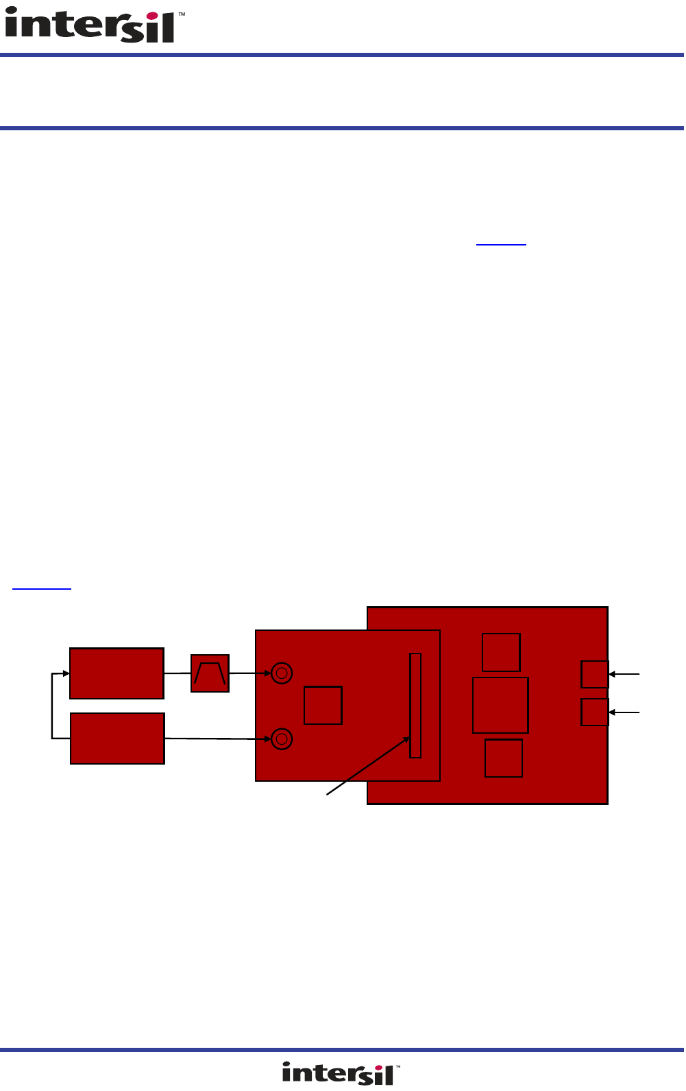
Figure 1. Evaluation Platform Block Diagram
Low-Jitter Signal
Generator
Low-Jitter Signal
Generator
ADC Evaluation Board
FPGA Based Data
Capture Board
Analog Input
Clock Input
10MHz
Reference
REF
OUT
REF
IN
AIN
CLK
ADC
FPGA Mezzanine
Connector (FMC)
FPGA
USB
SRAM
SRAM
+5V
USB to PC
DC Wall Supply

iRADAnalyzer 1. Functional Description
R34US0001EU0200 Rev.2.00 Page 2 of 18
Oct 18, 2022
1. Functional Description
The RHADC-FMCEV1Z motherboard is intended to operate with the iRADAnalyzer software along with a
radiation hardened precision SAR ADC evaluation board (daughterboard). The motherboard collects digitized
data from the daughter board ADC and relays that data to a PC running iRADAnalyzer so the data can be
analyzed for performance.
1.1 Hardware
There are two components in the hardware portion of the evaluation platform: the RHADC-FMCEV1Z
motherboard and the ADC daughter card (Figure 1
). The ADC is contained on the daughter card that contains the
analog input and clock circuitry. The daughter card interfaces with the motherboard through a High Pin Count
(HPC) FPGA Mezzanine Connector (FMC). The daughter card was designed to be compatible with the Vita 57.1
standard. The motherboard contains a USB interface, an FPGA, and four banks of SDRAM. The motherboard
serves as the interface between the host PC and the ADC daughter card. The daughter cards have jumpers that
set the operating voltages. The FPGA accepts output data from the ADC and buffers it in the SDRAMs before
passing it to the PC at a lower speed for post-processing. The maximum buffer depth is 32 Megawords (225),
however, the evaluation software is capable of processing data records only up to 1 Megaword (220) deep. If
usage of the full 32 Megaword depth is required.
You must supply the low-jitter analog signal generators for the clock and analog inputs to operate the daughter
card. Recommendations of suitable generators can be found in Appendix
: Analog Signal Generators. Many low-
jitter analog signal generators exhibit high harmonic spectral content relative to the ADC performance. A band-
pass filter is recommended to attenuate the harmonics.
1.2 Daughter Card
The daughter card is designed to produce optimal ADC performance and simplify the evaluation process. Some
boards have multiple connections for the analog input and clock.
1.2.1 Daughter Card Compatibility with FMC Host Cards
The daughter card connects to the motherboard through a High Pin Count (HPC) FPGA Mezzanine Connector
(FMC). The daughter card was designed to be compatible with the Vita 57.1 standard. This is intended to facilitate
the use of the daughter card with commercially available FMC host cards. These generators provide low jitter to
optimize the SNR performance of the ADC under test. Other generators with similar phase noise performance can
also be used. Contact Renesas Technical Support
for recommendations. Signals described as being sourced by
the Host must be provided by the FMC host card to the daughter card. These signals are necessary for the
daughter card to be fully functional. Signals described as being sourced by the daughter card are provided by the
daughter card to the host card. These signals can be optionally ignored by the host card if the functionality they
provide is deemed unnecessary.
1.3 Motherboard
The only connections required for the motherboard are a +5V power supply and a USB connection to the PC
running iRADAnalyzer. No additional configuration of the motherboard is required.
1.4 Software
The software component is iRADAnalyzer, a Graphical User Interface (GUI) created with Java. The GUI reads
data from the motherboard, optionally post-processes the data (FFT analysis), and displays the results. Data can
be viewed in the time or frequency domain and can be saved for processing later. Critical performance
parameters such as SNR, SFDR, and harmonic distortion are calculated and displayed on-screen when viewing
in the frequency domain.

iRADAnalyzer 1. Functional Description
R34US0001EU0200 Rev.2.00 Page 3 of 18
Oct 18, 2022
1.5 Installation Requirements
To operate the RHADC-FMCEV1Z motherboard, the iRADAnalyzer software must be installed. Before installing
the iRADAnalyzer, confirm the following:
• PC operating system is Windows 7 or greater.
• The account that the software is installed from has administrator privileges.
• Java is required for operation of the iRADAnalyzer software.
○ If the Java runtime environment is not installed on the PC, Java is installed during the installation of the
iRADAnalyzer software.
○ Windows has associated files with the *.jar extension with the java runtime environment. This is done by
default during the java runtime environment install. File extension associations can be modified by opening an
explorer window, clicking on the Tools drop-down menu, selecting Folder Options, and interacting with the
pop-up window.

iRADAnalyzer 2. Installing the iRADAnalyzer Software
R34US0001EU0200 Rev.2.00 Page 4 of 18
Oct 18, 2022
2. Installing the iRADAnalyzer Software
1. Double click the installer executable (that is, iRADAnalyzer_VX.XX.X.exe). This launches the installer,
resulting in the following window for language selection. Click Next >.
2. The install introduction page opens up showing the current version of the software, click Next > to continue.
Figure 2. Language Selection Window
Figure 3. Install Introduction Window

iRADAnalyzer 2. Installing the iRADAnalyzer Software
R34US0001EU0200 Rev.2.00 Page 5 of 18
Oct 18, 2022
3. In the License Agreement window, confirm the Software Evaluation License Agreement by clicking the IAgree
radio button, then click Next >.
4. The Choose Install Location window opens. Click Next >.
Figure 4. License Agreement Window
Figure 5. Choose Install Location Window

iRADAnalyzer 2. Installing the iRADAnalyzer Software
R34US0001EU0200 Rev.2.00 Page 6 of 18
Oct 18, 2022
5. The Choose Start Menu Folder window opens. If installing with administrative privileges, the For all users or
Only for the current user options can be selected to indicate which users the shortcuts are created for. Click
Next >.
6. The Additional Tasks window opens. Select the desired options for creating a desktop icon and for installing
the driver for the RHADC-FMCEV1Z. Note: If the USB driver has previously been installed, the Install Driver
check box can be left unchecked. Click Next >.
Figure 6. Choose Start Menu Folder Window
Figure 7. Additional Tasks Window

iRADAnalyzer 2. Installing the iRADAnalyzer Software
R34US0001EU0200 Rev.2.00 Page 7 of 18
Oct 18, 2022
7. The Complete Installation window opens. Click Install.
8. If the driver has not previously been installed, follow the prompts to install the driver. Select the check box to
always trust drivers from Renesas Electronics America Inc. and click Install.
Figure 8. Complete Installation Window
Figure 9. Install the USB Driver

iRADAnalyzer 2. Installing the iRADAnalyzer Software
R34US0001EU0200 Rev.2.00 Page 8 of 18
Oct 18, 2022
9. The Completing Renesas iRADAnalyzer Setup window opens. Click Finish.
Figure 10. Complete the iRADAnalyzer Installation

iRADAnalyzer 3. Evaluation Kit Setup
R34US0001EU0200 Rev.2.00 Page 9 of 18
Oct 18, 2022
3. Evaluation Kit Setup
1. Referencing to Figure 1, connect the daughter card to the motherboard by aligning the two mating FMC
connectors. Four screws on the motherboard (not shown) align with mounting holes in the daughter card.
2. Connect the analog signal generators to the Clock and Analog input SMA connectors.
3. Set the clock frequency as required with a power level of at least +0dBm (approximately 1.2V
PP
). Similarly, set
the analog input frequency with an appropriate power level depending on the connected ADC evaluation board
(the full-scale value varies depending on the loss of the input path, the gain of the ADC, and the reference
voltage of the ADC).
4. Apply +5V power (minimum 18W supply) to the motherboard. Unless otherwise stated in the ADC evaluation
board user guide, the motherboard can supply power to the daughter card. The daughter card contains power
conditioning circuitry to filter and convert the power provided by the motherboard (or external power supply) to
the voltages required by the daughter card circuitry. When the motherboard and the daughter card are powered
up, the analog signal generators can be turned on to supply the input signals to the ADC clock and analog
inputs.
5. The iRADAnalyzer software can be launched by double-clicking the iRADAnalyzer icon that should have been
copied to the desktop during the installation process (see the RHADC-FMCEV1Z User Manual for detailed
installation instructions). iRADAnalyzer can also be launched by selecting Start→All Programs→Renesas
iRADAnalyzer→iRADAnalyzer. The main iRADAnalyzer window opens.
6. If the hardware has been set up as previously described, data collection can proceed by pressing the Data
Capture button. If the hardware has not been configured or is not functioning properly, the Data Capture
button is inactive and an Init Eval Kit button is displayed. In this case, the Init Eval Kit button should be
pressed when the hardware has been connected.

iRADAnalyzer 4. Overview of Software Features
R34US0001EU0200 Rev.2.00 Page 10 of 18
Oct 18, 2022
4. Overview of Software Features
iRADAnalyzer is the evaluation kit control software for the evaluation of Rensas’ newest radiation hardened
precision SAR ADC products. The remainder of this guide assumes the iRADAnalyzer software has been
installed by following the iRADAnalyzer installation guide.
Double-clicking on the desktop shortcut iRADAnalyzer brings up a window similar to the one shown in Figure 11
.
With a daughterboard attached, iRADAnalyzer should indicate that the board is initialized.
Note: iRADAnalyzer can be run without the hardware attached to analyze previous data captures.
After clicking on the Data Capture button with a powered-up evaluation kit attached, a window similar to the
following is displayed. Figure 12
shows the major portions of the iRADAnalyzer GUI.
Figure 11. Board Initialization
Figure 12. iRADAnalyzer GUI
Pull-Down Menus
Frequency or
Time Display
Performance
Characteristics
Product
Information
FFT Window
Options
Zoom options and user messages (errors, warnings, and information notifications)
Graphical Data Display and Options
Data Capture
Options

iRADAnalyzer 4. Overview of Software Features
R34US0001EU0200 Rev.2.00 Page 11 of 18
Oct 18, 2022
Clicking on the Time or Frequency display panel changes the display of the current capture between time and
frequency domain. The typical ADC performance characteristics, as calculated from the current data capture, are
shown in the upper-left area of the GUI (such as SNR, SFDR, H2, H3, and ENOB). The product information is
shown in the lower-left area of the GUI. The product information includes the ADC product name, the number of
samples captured, and analog and digital power consumption of the ADC, as measured during the last data
capture.
4.1 File Menu
The File pull-down menu contains the following selections:
• Open Data File
• Save Data File
• Open Configuration File
• Save Configuration File
•Print
• Exit
4.1.1 Open Data File
By clicking on Open Data File, the GUI opens a previously saved Comma Separated Format (CSV) file and
analyzes the data as if it was received from the evaluation kit. CSV is an industry-standard text format. The CSV
files saved and loaded by iRADAnalyzer have one ADC sample per line, with each sample represented by a
decimal number. The decimal number is generated by taking the raw ADC data in unsigned magnitude format and
left shifting as needed until the MSB of the ADC sample is in bit position 16, with the resulting binary number
being represented as a decimal. This default format has the advantage that a program can load this CSV file
without having prior knowledge of the resolution of the ADC. As an option, iRADAnalyzer can also load and save
more traditional LSB-justified CSV files from the Tools→Option drop-down selection.
4.1.2 Save Data File
By clicking on Save Data File, the GUI saves the currently displayed data as a CSV file. The saved data is always
in the time domain, irrespective of the graphical time or frequency domain display selection.
Figure 13. File Menu
Figure 14. Save Data Options

iRADAnalyzer 4. Overview of Software Features
R34US0001EU0200 Rev.2.00 Page 12 of 18
Oct 18, 2022
4.1.3 Open Configuration File
By clicking on Open Configuration File, the GUI opens the configuration file previously saved by iRADAnalyzer.
Configuration files are a convenient way to save settings for the iRADAnalyzer, including FFT windowing,
continuous capture, FFT bin width settings, data capture setting such as number of samples.
4.1.4 Save Configuration File
By clicking on Save Configuration File, the GUI saves the configuration state of iRADAnalyzer into a
configuration file.
4.1.5 Print
By clicking on Print, the GUI brings up the printing window.
4.1.6 Exit
By clicking on Exit, the GUI exits iRADAnalyzer.
4.2 Edit Menu
The Edit pull-down menu contains the following selections:
• Data Capture
• Connect to Eval Hardware
4.2.1 Data Capture
By clicking on Data Capture, the GUI brings up a window that allows you to configure the data capture operation.
Each of these settings affects data captures from the hardware and from CSV files read in. Available parameters
that can be set are shown in Figure 16
.
Figure 15. Edit Menu
Figure 16. Data Capture Parameters

iRADAnalyzer 4. Overview of Software Features
R34US0001EU0200 Rev.2.00 Page 13 of 18
Oct 18, 2022
4.2.1.1 Number of Samples
The number of contiguous samples in each capture can be selected each time the Data Capture button is
pressed. This number is automatically rounded up to the next largest power of 2 as required by the FFT routine of
the iRADAnalyzer. The hardware supports up to 32Meg (2
25
) continuous data samples captured.
IMPORTANT: Downloading in excess of 4Meg (2
22
) samples can result in long capture times and can cause the
program to run out of memory.
4.2.1.2 Input Clock Frequency
The Input Clock Frequency field allows you to set the input clock frequency for subsequent data analysis, which
calculates the sample rate based on the product type and device settings. When reading in data from a CSV file,
the sample rate is read into iRADAnalyzer from the file and updated accordingly.
4.2.1.3 Calculate Coherent Frequency
The Calculate Coherent Frequency field allows you to calculate the coherent frequency for sampling with no
windowing. Input the required frequency into the box labeled Preferred Sinusoid input signal freq. after the
required mode of the product is selected. This calculation can be updated to provide the appropriate frequency for
the input frequency, number of samples selected, and the sample rate.
4.2.1.4 Reset Eval Hardware
When the Reset Eval Hardware button is selected, the entire evaluation kit hardware is re-initialized. This
process takes several seconds to complete.
4.3 Tools Menu
The Tools pull-down menu contains the following selection:
• Options
Figure 17. Tools Menu

iRADAnalyzer 4. Overview of Software Features
R34US0001EU0200 Rev.2.00 Page 14 of 18
Oct 18, 2022
4.3.1 Options
The Options selection allows you to set the iRADAnalyzer options to adjust the behavior of the software, as
required.
4.4 Device Menu
The device menu allows you to see the information for the connected product, configure the connected product,
and reset the data capture board.
Figure 18. Options Window
Figure 19. Device Menu

iRADAnalyzer 4. Overview of Software Features
R34US0001EU0200 Rev.2.00 Page 15 of 18
Oct 18, 2022
4.4.1 Configuration
The information about the connected product and data capture board status are provided in this menu
(ISL73148SEH shown as an example).
4.4.2 Settings
The settings for the connected product are configured using this menu. Depending on the connected product,
different options are populated for you to select the required mode of operation.
4.4.3 Reset Eval Hardware
When Reset Eval Hardware is selected, the entire evaluation kit hardware is re-initialized. Press the reset button
on the RHADC-FMCEV1Z board before clicking the Done button on this menu. This process takes several
seconds to complete.
Figure 20. Device Configuration Menu
Figure 21. Reset Eval Hardware Menu

iRADAnalyzer 4. Overview of Software Features
R34US0001EU0200 Rev.2.00 Page 16 of 18
Oct 18, 2022
4.5 Help Menu
The Help pull-down menu contains the following selections:
• Device Link
• Online Feedback
• About
The Help drop-down menu contains links to various on-line resources for acquiring device information, updating
the iRADAnalyzer software, obtaining information on the software version, and obtaining the serial number of the
connected evaluation board.
4.5.1 About Menu
The about menu provides information about the version of software and the serial number for the evaluation
board that is attached to the RHADC-FMCEV1Z board.
Figure 22. Help Menu
Figure 23. Help - About Menu

iRADAnalyzer 5. Appendix: Analog Signal Generators
R34US0001EU0200 Rev.2.00 Page 17 of 18
Oct 18, 2022
5. Appendix: Analog Signal Generators
Renesas uses the following analog signal generators as clock and signal sources when characterizing low-power,
high-performance radiation hardened precision SAR ADCs:
• Rohde & Schwarz: SMA100A or SMA100B (with low phase noise and clock synthesis options)
• Audio Precision SYS-2722 Audio Analyzer/Generator
These generators provide very low jitter to optimize the SNR performance of the ADC under test. Other
generators with similar phase noise performance can also be used. Contact Renesas Technical Support
for
recommendations.

iRADAnalyzer 6. Revision History
R34US0001EU0200 Rev.2.00 Page 18 of 18
Oct 18, 2022
6. Revision History
Rev. Date Description
2.00 Oct 18, 2022 Changed tolerant to hardened throughout document.
Updated Specifications section.
Updated PC operating system requirements.
Updated Evaluation Kit Setup section.
Updated Figures 11, 12, 14, 16, 19, and 20
Changed Sample Rate section to Input Clock Frequency section.
Changed Number of Bits in Each Sample section to Calculate Coherent Frequency section.
Removed Measure menu section and subsections.
Removed the Options subsections.
Added Device Menu section and subsections.
Updated Help Menu section.
Added About Menu section.
Updated Appendix section.
1.01 Jun 15, 2021 Updated the Installation Requirements section.
1.00 Aug 26, 2020 Initial release

Corporate Headquarters
TOYOSU FORESIA, 3-2-24 Toyosu,
Koto-ku, Tokyo 135-0061, Japan
www.renesas.com
Contact Information
For further information on a product, technology, the most
up-to-date version of a document, or your nearest sales
office, please visit:
www.renesas.com/contact/
Trademarks
Renesas and the Renesas logo are trademarks of Renesas
Electronics Corporation. All trademarks and registered
trademarks are the property of their respective owners.
IMPORTANT NOTICE AND DISCLAIMER
RENESAS ELECTRONICS CORPORATION AND ITS SUBSIDIARIES (“RENESAS”) PROVIDES TECHNICAL
SPECIFICATIONS AND RELIABILITY DATA (INCLUDING DATASHEETS), DESIGN RESOURCES (INCLUDING
REFERENCE DESIGNS), APPLICATION OR OTHER DESIGN ADVICE, WEB TOOLS, SAFETY INFORMATION, AND
OTHER RESOURCES “AS IS” AND WITH ALL FAULTS, AND DISCLAIMS ALL WARRANTIES, EXPRESS OR IMPLIED,
INCLUDING, WITHOUT LIMITATION, ANY IMPLIED WARRANTIES OF MERCHANTABILITY, FITNESS FOR A
PARTICULAR PURPOSE, OR NON-INFRINGEMENT OF THIRD PARTY INTELLECTUAL PROPERTY RIGHTS.
These resources are intended for developers skilled in the art designing with Renesas products. You are solely responsible
for (1) selecting the appropriate products for your application, (2) designing, validating, and testing your application, and (3)
ensuring your application meets applicable standards, and any other safety, security, or other requirements. These
resources are subject to change without notice. Renesas grants you permission to use these resources only for
development of an application that uses Renesas products. Other reproduction or use of these resources is strictly
prohibited. No license is granted to any other Renesas intellectual property or to any third party intellectual property.
Renesas disclaims responsibility for, and you will fully indemnify Renesas and its representatives against, any claims,
damages, costs, losses, or liabilities arising out of your use of these resources. Renesas' products are provided only subject
to Renesas' Terms and Conditions of Sale or other applicable terms agreed to in writing. No use of any Renesas resources
expands or otherwise alters any applicable warranties or warranty disclaimers for these products.
(Rev.1.0 Mar 2020)
