
9/24/2018
1
Time Overcurrent Relays
U
I
ECE525
Lecture 11
Time Overcurrent Relays
More or less
approximates
thermal fuse
» Allow
coordination
with fuses
Reset
Position
Time Dial
Setting
Direction
of
Current
Induced
Torque
Restraining
Spring
Disk
Time Overcurrent Relays
U
I
ECE525
Lecture 11
Basic equation
s
= restraining spring
torque
I = applied current
I
p
= pick up current
K
d
= disk damping
factor
= angle of disk
rotation (proportional
to Time Dial Setting
(TDS)
t
K
I
I
T
d
p
s
1
2
Operating torque Restraining Torque

9/24/2018
2
Time Overcurrent Relays
U
I
ECE525
Lecture 11
Relay Response
12
2
12
1 tt
I
I
K
pd
s
t
K
I
I
d
p
s
1
2
1. Operating torque = Restraining Torque
2. Integrate w.r.t. Time
timetrip
I
I
K
TDS
pd
s
1
2
3. TDS (setting angle),
where triptime = t
2
-t
1
Time Overcurrent Relays
U
I
ECE525
Lecture 11
Relay Response
4. Finding trip time
1
1
2
2
M
A
TDS
I
I
K
TDStimetrip
p
s
d
Where: M = I/I
p
A = K
d
/t
s

9/24/2018
3
Time Overcurrent Relays
U
I
ECE525
Lecture 11
Standard Curves --
standard formats
2
1 M
C
TDStr
B
M
A
TDStt
p
1
Reset Time (M < 1)
Trip time (M
1)
Some manufacturers include disk inertia in B
Time Overcurrent Relays
U
I
ECE525
Lecture 11
US and IEC curve
parameters
Curve A B C P
U.S. Moderately inverse (U1) 0.0104 0.2256 1.08 0.02
U.S. Inverse (U2) 5.95 0.180 5.95 2.00
U.S. Very inverse (U3) 3.88 0.0963 3.88 2.00
U.S. Extremely inverse (U4) 5.67 0352 5.67 2.00
U.S. Short-time inverse (U5) 0.00342 0.00262 0.323 0.02
I.E.C. Class A - Standard inverse (C1) 0.14 0.0 13.5 0.02
I.E.C. Class B – Very inverse (C2) 13.5 0.0 47.3 2.00
I.E.C. Class C – Extremely inverse (C3) 80.0 0.0 80.0 2.00
I.E.C Long-time inverse (C4) 120.0 0.0 120.0 2.00
I.E.C Short-time inverse (C5) 0.05 0.0 4.85 0.04

9/24/2018
4
Time Overcurrent Relays
U
I
ECE525
Lecture 11
US Inverse (U2)
Characteristic
Time Overcurrent Relays
U
I
ECE525
Lecture 11
Comparison of curves

9/24/2018
5
Time Overcurrent Relays
U
I
ECE525
Lecture 11
Extremely Inverse Curve
and 50E fuse
Time Overcurrent Relays
U
I
ECE525
Lecture 11
Example
Vs
Z1
Local
Load
Local
Load
Local
Load
Faulted
Line
Bus
#1
Bus
#2
Bus
#3
Z3
Z4
Z2
Source
R3R2
R4
• Want the relay on the faulted line, R4, to be the only relay to trip
• Max and min fault current (based on ends of faulted line)
1 2 3
1 2 3 4

9/24/2018
6
Time Overcurrent Relays
U
I
ECE525
Lecture 11
Example continued
The desired coordination can be accomplished by:
increasing the time dial settings as one proceeds toward
the source.
» If relay R2 is expected to provide backup protection for
relay R4,
» Then R4, the relay with the greatest source impedance, would
be set with the lowest time dial setting
Time Overcurrent Relays
U
I
ECE525
Lecture 11
Example continued
» If I
MIN
is defined as the minimum fault current,
» Then the pickup current must be set at or below this current but
above maximum load current.
» Usually with a margin around both
» For relays R2 and R3, the TDS must be set to trip no
faster then the next downstream device when the fault
current is maximum for an out of zone fault
9/24/2018
7
Time Overcurrent Relays
U
I
ECE525
Lecture 11
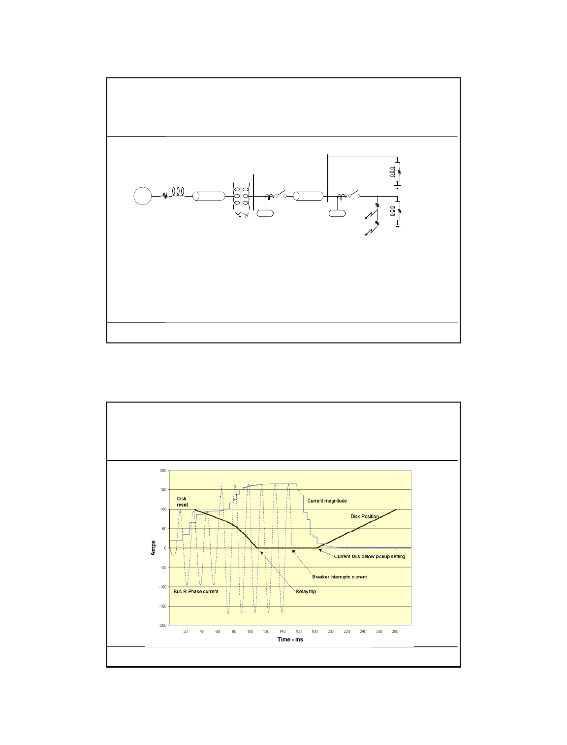
EMTP relay simulation
Gen
Xfmr
Breaker
Breaker
Source
Impedance
230KV
Fault #2
C-G
Fault #1
C-G
69KV
52 52
S Bus
R Bus
Load
Load
225
25
250 resistive fault is initiated at 8.3 ms and progresses to a 25 fault at 62 ms
as can occur by a tree branch coming in contact with the wire.
Time Overcurrent Relays
U
I
ECE525
Lecture 11
Example with a trip

9/24/2018
8
Time Overcurrent Relays
U
I
ECE525
Lecture 11
Comparing relay
coordination (light load)
Time Overcurrent Relays
U
I
ECE525
Lecture 11
Comparing relay
coordination (heavy load)

9/24/2018
9
Time Overcurrent Relays
U
I
ECE525
Lecture 11
Directional Control vs
Direction Supervision
32
Directional
Element
(32)
Reference
Signal
Phase
Current
50/
51
Overcurrent
Element
(50 or 51)
Phase
Current
50/51
52
DC Bus -
AC Circuit
Breaker
b. Directional Control
32
DC Bus +
32
Directional
Element
(32)
Reference
Signal
Phase
Current
50/
51
Overcurrent
Element
(50 or 51)
Phase
Current
32
50/51
52
DC Bus +
DC Bus -
AC Circuit
Breaker
a. Directional Supervision
Time Overcurrent Relays
U
I
ECE525
Lecture 11
Directional Step-Time
Overcurrent (ANSI 67)
The directional overcurrent relay can be perceived as a
type 50 instantaneous element controlled by a type 32
directional element
If the type 67 relay element is to provide backup protection,
they use definite time delay for downstream coordination
The 67 element requires more attention to detail for
coordination than do type 51 relays
» The advantage that the stepped time has over the 51 is that
the time steps are independently set
.
» The disadvantage is that overreach errors have a more
pronounced affect that often proves difficult to
coordinate

9/24/2018
10
Time Overcurrent Relays
U
I
ECE525
Lecture 11
Directional Step-Time
Overcurrent (ANSI 67)
Bus S
2
G 1
Load
1
Load
2
Load
3
Load
4
F1 F2 F3 F4
Load 5
Increasing
time
51
67
Time Overcurrent Relays
U
I
ECE525
Lecture 11
Overcurrent Elements in
Microprocessor Relays
Expect the relay to be able to coordinate with
fuses and electromechanical relays
Implement relay function using the standard
curve equations
Use digital filters to compute RMS magnitude
from measured currents
Add directional supervision
Take advantage of some calculations difficult
to do without microprocessor
