
U.S. CONSUMER PRODUCT SAFETY COMMISSION
Directorate for Engineering Sciences
AN EVALUATION OF USING
INDICATORS TO INFORM CONSUMERS
OF CLOTHES DRYER STATUS
June l, 2011
Arthur Lee
Electrical Engineer
Division of Electrical Engineering
Directorate for Engineering Sciences
Rana Balci-Sinha
Engineering Psychologist
Division of Human Factors
Directorate for Engineering Sciences
Matthew Hnatov
Mathematical Statistician
Division of Hazard Analysis
Directorate for Epidemiology
Leigh-Anne Edwards
Intern
Division of Mechanical Engineering
Directorate for Engineering Sciences
This report was prepared by CPSC staff and has not been reviewed or approved by,
and may not necessarily reflect the views of, the Commission.

ii
Table of Contents
1.0 INTRODUCTION ........................................................................................................... 1
1.1 Background ......................................................................................................................... 1
1.2 Project Objectives ............................................................................................................... 1
2.0 CLOTHES DRYERS ....................................................................................................... 1
2.1 Basic Dryer Operation ......................................................................................................... 2
2.2 High-Limit Thermostat Operation ....................................................................................... 2
3.0 FACTORS CONTRIBUTING TO DRYER FIRES ........................................................ 3
4.0 CHANGES TO THE VOLUNTARY STANDARD ....................................................... 4
5.0 STATUS INDICATORS ................................................................................................. 5
5.1 Reminders – Maintenance Indicators .................................................................................. 5
5.2 Warnings – Operating Status Indicators .............................................................................. 6
5.3 Status Indicators for Maintenance and Operation ............................................................... 7
6.0 EXAMPLES OF INCIDENTS THAT POSSIBLY WOULD HAVE BEEN
MITIGATED BY A STATUS INDICATOR ................................................................ 10
6.1 Three Years Old or Less .................................................................................................... 11
6.2 Three to Five Years Old .................................................................................................... 11
6.3 Five to Ten Years Old ....................................................................................................... 13
6.4 More Than Ten Years Old................................................................................................. 13
7.0 INCORPORATING STATUS INDICATORS.............................................................. 14
8.0 CONCLUSION .............................................................................................................. 17
Bibliography ........................................................................................................................... 18
APPENDIX ............................................................................................................................. 19
A.1 Auditory Displays ................................................................................................................ 19
A.2 Increasing Detectability of Auditory Signals ...................................................................... 20
A.3 Signal and Warning Lights .................................................................................................. 20
List of Figures
Figure 1. Heater Housing Temperatures, High-Limit Thermostat Cycling ..................................... 3
Figure 2. Warning Signal for Specific Operating Conditions .......................................................... 7
Figure 3. Example of Status Indicator Lights for a Dryer................................................................ 8
Figure 4. Passive and Active Monitoring for Clean Lint Filter Indicator........................................ 9
Figure 5. Passive Monitoring for Clean Dryer Duct and Cabinet Indicator.................................... 9
Figure 6. Passive Monitoring for Clean Dryer Duct and Cabinet Indicator.................................. 10
Figure 7. Cross-sectional View of Single-Pole, Single-Throw High-Limit Thermostat ............... 14
Figure 8. Cross-sectional View of Single-Pole, Double-Throw High-Limit Thermostat .............. 15
Figure 9. Incorporating a Service Required Indicator .................................................................... 15
Figure 10. Incorporating Clean Lint Filter and Clean Dryer Duct and Cabinet Indicators .......... 16

1
1.0 INTRODUCTION
The U.S. Consumer Product Safety Commission (CPSC) staff conducted an evaluation
on incorporating warning indicators into the design of clothes dryers to alert consumers to
potentially hazardous situations. This report describes the results of that evaluation.
From 2003 to 2005, the latest years for which data are available, CPSC staff estimates
that there was an annual average of 6,900 residential structure fires attributed to clothes dryers.
The estimated annual average of fire injuries was 200. The estimated annual average of fire
deaths was less than 10 (Chowdhury, Greene, & Miller, 2008).
1.1 Background
In 2003, CPSC staff completed its Final Report on Electric Clothes Dryers and Lint
Ignition Characteristics (Lee, 2003). In the report, CPSC staff investigated the possible
relationship between lint ignition and fires in clothes dryers. CPSC staff tested a selection of
clothes dryers to evaluate the effects of lint accumulation on operating temperatures to determine
whether such conditions may result in lint ignition and/or dryer fires.
The data were used to help determine if dryer fires result from a single event or a
combination of events. The results of the staff’s evaluation demonstrated that lint accumulates
and ignites when in contact with a hot surface, such as the heating element or heater housing.
The evaluation also demonstrated that lint contacting the heater housing, and in proximity to the
heater intake, can ignite itself and accumulated lint material downstream of the heater, such as
accumulated lint within a dryer duct. It was determined that lint may still accumulate inside a
dryer, even with properly vented exhaust ducting and routine cleaning of the lint screen before
each load. The testing also showed that dryers cycled on the high-limit thermostat when the
exhaust vent was 75 or 100 percent blocked, which caused the temperatures near the heater to
increase significantly.
1.2 Project Objectives
CPSC staff conducted this evaluation to determine whether indicators could be used to
inform a user that a clothes dryer requires maintenance or is operating abnormally, with the
potential to prevent a hazardous scenario.
2.0 CLOTHES DRYERS
The life expectancy of a clothes dryer depends on the extent of use it receives. From a
CPSC staff survey,
1
on average, consumers reported drying approximately six loads of clothes
per week, with larger families using clothes dryers more frequently (Balci-Sinha, 2010). Dryers,
either electric or gas, last about 13 years, but are often replaced long before they are worn out
1
The CPSC staff survey was not a random sample of the U.S. population but, rather, a convenience population
sample. Therefore, the survey results may not be representative of the general population. The respondent
population was more likely than the public to be aware of safety issues, so unsafe behaviors or low hazard
perceptions among this population most likely would point to problems that would be more prevalent among the
general consumer population.

2
because changes in styling, technology, and consumer preferences make newer products more
desirable (NAHB, 2007).
2.1 Basic Dryer Operation
The basic airflow path in clothes dryers, as indicated in the 2003 CPSC staff report, has
changed little over the years. Air is pulled into the dryer through any gaps in the dryer housing,
particularly through rear vents. Air is drawn over the heater, where it is warmed, before it enters
the tumbler. The air exits the tumbler through the lint screen. It then passes through a duct and
into a fan. The fan forces the air through an exiting duct to the rear of the dryer, which is
connected to external ducting that is routed to the outside of the home.
2.2 High-Limit Thermostat Operation
A high-limit thermostat is found in almost all clothes dryers. Typically, a high-limit
thermostat is located near or within the heater housing. The high-limit thermostat is designed to
activate at a manufacturer pre-determined set point (i.e., when there is excessive heat in the
heater area). When activated, the high-limit themostat or switch disconnects power to the
heating element. The high-limit thermostat is automatically resettable, which means that it resets
itself when the temperature has cooled to a specific set point. In the 2003 CPSC staff testing,
staff evaluated the activation responses of high-limit thermostats for various clothes dryer
designs. Figure 1 shows the graph of one dryer design (Dryer Design C), cycling on the high-
limit thermostat when the exhaust vent was 75 percent or 100 percent blocked. The operation of
the high-limit thermostat prevented the heater box temperature from increasing much higher than
80°C.
There may be no indication to a user when their clothes dryer is operating on the high-
limit thermostat, or in an abnormal condition. Typically, when a dryer is operating in the high-
limit cycling mode, the clothes in the dryer are still damp at the end of the drying cycle; and this
may be the only indication to the user that the dryer is not operating efficiently.

3
Final Report on Electric Clothes Dryers and Lint Ignition Characteristics, May 2003
Figure 30. Dryer Design C – T3 Heater Housing Comparison
Figure 1. Heater Housing Temperatures, High-Limit Thermostat Cycling
3.0 FACTORS CONTRIBUTING TO DRYER FIRES
Two recent reports, one by the U.S. Fire Administration (USFA), and one by the National
Fire Protection Association (NFPA), on clothes dryer fires in the United States both indicate that
the two leading factors associated with dryer fires are mechanical failures and failure to clean the
airways. The USFA report uses data from 2002 to 2004, and the NFPA report uses data from
2003 to 2006.
According to the NFPA report, failure to clean airways accounted for an annual average
of 31 percent of the dryer fires, followed by mechanical failure at 23 percent (Hall, 2009). The
NFPA estimates are based on data from the USFA’s National Fire Incident Reporting System
(NFIRS) and NFPA’s annual fire department experience survey.
According to the USFA report, most fires occurred in one- and two-family residences and
accounted for 81 percent of residential building clothes dryer fires (FEMA, 2007). Clothes dryer
fires typically occurred between 8 a.m. and midnight. The report states that the leading factor
contributing to ignition of clothes dryer fires is operational deficiencies (43 percent), followed by
mechanical failure (32.6 percent). Failure to clean the airways and ducts is included in the
4
category of operational deficiencies, which accounted for 70 percent of the fires in this category.
This category includes not cleaning the lint and dust around and inside of the dryer, as well as
not cleaning accumulated lint inside the dryer ducts. According to the report, when a dryer fire
occurs, the most likely items to ignite first are wearing apparel, not on a person and/or dust,
fiber, lint, etc. Wearing apparel, not on a person refers most likely to the clothes load in the
dryer, or possibly, clothing near the dryer. Dust, fiber, lint, etc. can include this debris any place
that collects dust and lint, such as within the dryer chassis, on the lint screen, around the dryer,
and in the ducting that carries the lint from the dryer to the outside.
The number of home fires involving electric-powered clothes dryers outnumbered fires
involving gas-fueled clothes dryers by 3.2 to 1, as indicated in the NFPA report (Hall, 2009). In
CPSC staff’s survey of clothes dryer use, the ratio of electric to gas clothes dryers owned by
consumers was 3.4 to 1, which indicates that one type of fuel source for clothes dryers does not
necessarily have higher chances of fires (Balci-Sinha, 2010).
In 2002, the Association of Home Appliance Manufacturers (AHAM) released a report
that analyzed clothes dryer fire incidents by using industry-collected data (AHAM, 2002).
AHAM and member companies who manufacture clothes dryers conducted a data collection
program on clothes dryer fire incidents from February 2001 through August 2001. The goal of
the survey was to collect data from approximately 200 reported incidents. In the end, data was
collected on a total of 191 clothes dryer incidents. The number of clothes dryer incidents that
each manufacturer compiled was based on an approximation of that company’s market share as
published by industry trade magazines. The report states that the ratio of fire reports on electric
and gas clothes dryers did not differ from the ratio of electric and gas clothes dryers installed in
U.S. residences. In the cases where some evidence of a fire was observed, the analysis of the
data could not determine a single cause that would stand out as a leading contributor to dryer
fires. The causes of dryer fires were reported to be the result of many potential contributing
factors, such as the load, electrical system, mechanical system, and gas system. In 66 out of the
191 incidents investigated, the drum was identified as the area of involvement.
4.0 CHANGES TO THE VOLUNTARY STANDARD
Underwriters Laboratories Inc. (UL) recently revised its voluntary standard, UL 2158 -
Electric Clothes Dryers, to include performance requirements to contain fires within a dryer.
These requirements will become effective in March 2013. After March 20, 2013, clothes dryers
listed to UL 2158 must meet a series of fire containment tests. Fires in the tumbler and the inside
base of the dryer chassis will be required to be contained within the dryer. The tests use
cheesecloth draped over the entire dryer as an indicator of whether the fire has escaped the dryer
(Underwriters Laboratories Inc., 2009).
While these additional performance tests should help lower the severity of clothes dryer
fires by containing a fire and not allowing it to spread to nearby combustibles, changes to dryer
designs that will be necessary to pass the performance tests will mostly likely not reduce the
leading causes of dryer fires: ignition of lint, dust, fibers, etc. and mechanical failures.

5
5.0 STATUS INDICATORS
UL 2158 does not require clothes dryers to provide feedback to a user on the “health” of
the dryer. Without the user knowing, a dryer could be operating in a potentially unsafe mode for
an extended period of time, which has the potential to escalate into a hazardous fire condition.
Status indicators, whether visual and/or audible, could be useful tools for informing a user that
their clothes dryer is not operating correctly or that a routine maintenance task needs to be
performed. The use of status indicators may be divided into two categories: reminders and
warnings.
5.1 Reminders – Maintenance Indicators
Indicators have been widely used on various appliances to inform or remind consumers
of the specific status of an appliance. Some central heating thermostats have been designed to
inform consumers when they need to change their furnace filter. These reminders can be
triggered by something as simple as a timer, from the time the homeowner previously changed
the filter, to a sensor that actually detects the amount of debris on the filters. Vacuum cleaners
have incorporated feedback indicators to give consumers a visual indication of how full the
vacuum bag is and when it needs to be changed. While these indicators or reminders are not
designed to be safety features, they provide important feedback to the consumer and allow the
appliance to operate more efficiently and under less strain, which may ultimately prevent
component failure.
In a 2010 CPSC staff online survey
2
on the clothes dryer maintenance habits of
consumers, more than 80 percent of the respondents indicated that they typically clean their
dryer lint filters once every load or every other load (Balci-Sinha, 2010). Seventy-one percent of
the respondents stated that they check their dryer exhaust exits for blockages. As might be
expected, when the task includes removing or cleaning lint from a less accessible area and, thus,
becomes more difficult, the likelihood that the task is performed decreases. Sixty-two percent of
respondents stated that they cleaned under the lint filter; 38 percent said they cleaned inside the
dryer ducts; and 20 percent reported that they cleaned inside the dryer cabinet. In some cases,
surveyed respondents stated that the inside of the cabinet or the dryer duct was cleaned when a
repair was performed on the dryer or dryer duct.
As stated earlier in this report, CPSC staff testing in 2003 showed that lint accumulates
inside a dryer even when the dryer’s lint screen has been cleaned after each use and the dryer is
exhausted properly. In addition, dust, fiber, lint, etc. are among the first items to ignite in a
clothes dryer fire.
Maintenance indicators could provide a convenient reminder to consumers to clean inside
the dryer chassis and dryer duct. Counting dryer loads is one easy method that could be used for
an indicator control to remind consumers when a task needs to be performed (e.g., check and
clean the exhaust exit, exhaust duct, and inside the dryer cabinet). The specific number of dryer
2
The CPSC staff survey was not a random sample of the U.S. population but, rather, a convenience population
sample and, therefore, the survey results may not be representative of the general population.

6
loads counted to signal that maintenance or a cleaning task needs to be performed would be
manufacturer and dryer-design specific.
5.2 Warnings – Operating Status Indicators
Operating status indicators to inform consumers on the “health” of a product are used
across a wide range of applications, but mainly can be found on products that are costly or would
create a high-level hazard if the product were to fail. Expensive items, such as automobiles,
have incorporated multiple feedback indicators to inform the driver on the “health” of various
vehicle systems or components. The “check engine” or “air bag” lights are two common
operating status indicators on automobiles that, if not attended to, may cause the vehicle to fail
completely during an untimely situation, not provide protection in an accident, or result in more
costly repairs. Some appliances have incorporated operating status indicators to prevent
untimely failures or a hazardous situation. Gas appliances use sensors to verify that the burner
has ignited and, if not, the gas valve is closed. Feedback to the user that the appliance failed to
ignite may be a simple flashing indicator. Ground fault circuit interrupters (GFCI) have been
designed with indicator lights to allow feedback to consumers if the GFCI is properly installed
and operating correctly to provide protection against electrical faults. These operating status
indicators are not only designed as feedback indicators to the user, but they also may be
considered safety features because failure could result in a hazardous situation.
Clothes that are drying in progressively longer cycle times or clothes that are still damp at
the end of a drying cycle may be the only indications to a consumer that their clothes dryer is not
operating properly (i.e., that it is not operating under normal conditions). Consumers may
overlook the hint that still-damp clothes might indicate something is not correct; moreover,
consumers may run the dryer again in an attempt to dry the load. In this instance, the dryer may
be cycling on the high-limit thermostat, which is designed to prevent excessive heat buildup
around the heater.
Feedback on the operating status of the high-limit thermostat could be a valuable
indicator that service needs to be performed on the dryer system. The dryer can enter into a
high-limit cycling mode from a number of conditions, such as an overload, a blocked exhaust
duct, and a blocked lint screen, as shown in Figure 2. All of these conditions typically result in
reduced airflow through the dryer system, causing excessive heat at the heater location. In
addition, depending on dryer design, a primary thermostat that fails to operate may trigger the
high-limit thermostat to begin cycling (Lee, 2003).
If the high-limit thermostat fails to operate, clothes dryers have a secondary safety feature
that will activate. Typically, a one-shot thermal fuse is located near the high-limit thermostat
and has a higher activation set point. When the one-shot activates, it disconnects power to the
heating element and, in some designs, power to other parts of the dryer. When a one-shot has
activated, the dryer will not heat until the part is replaced, which requires a qualified technician.
Even though a consumer will know at this point that something is wrong with their dryer, a status
indicator may still be beneficial. An indicator light that signals the dryer needs servicing would
inform the user that the dryer has experienced an internal failure.

7
Figure 2. Warning Signal for Specific Operating Conditions
5.3 Status Indicators for Maintenance and Operation
A status indicator is effective only if the user understands and acts on the notification. A
poor indicator design decreases the chances that the user will embrace the message. An indicator
light that is too small or dark may not be noticed by the user. A series of indicator lights without
explanation or text may be confusing and ignored. The appendix contains information on
different types of indicators and their purposes.
The background color of the control panel and room lighting can influence the
effectiveness of indicator lights for users to detect and respond to the message. The intensity or
color of the light may vary if clothes dryer color is different, such as white, black, or stainless
steel. A dryer located in a basement or closet with poor lighting may provide a more effective
indicator light than a dryer in a well-lit room. But with low signal-to-background brightness
contrast, a red signal has a marked advantage in attracting attention, followed by green, yellow,
and white, in that order.
Overloaded
Tumbler
Blocked Exhaust
Duct
Severely Blocked
Lint Screen
Failed Primary
Thermostat
No heat and
possibly dryer
shuts down
Overheated,
which may lead
to fire
OPERATING
CONDITION
High-Limit
Thermostat
One-Shot
Thermostat
WARNING
SIGNAL
operates
operates
fails to
operate
fails to
operate

8
Red indicator lights typically have been used to inform users of an urgent situation that
needs immediate attention because the system has become inoperative and/or may pose a life-
threatening situation. Yellow indicator lights have been used to alert users of a cautious situation
that may not require immediate attention, but is a condition that, if not attended to, could lead to
a dangerous situation. Green indicator lights have been used to indicate that equipment is
operating satisfactorily or without problems.
A flashing indicator light can be more effective at attracting attention. An illustration of
possible indicator lights and text to inform the user on the status of the dryer is shown in Figure
3. To be the effective, the size of the indicator lights should be at least one-half of an inch to
provide enough illumination and surface area to attract the attention of the user. Clean Lint
Filter and Clean Dryer Duct and Cabinet indicator lights are solid yellow when activated. While
it is important that these maintenance services are performed, they do not necessarily require
immediate attention. The Service Required indicator is a flashing red light when activated. The
flash rate should be well below a flashing light that could appear to be a steady light. In this
situation, the dryer is operating on the high-limit thermostat, or the primary thermostat has failed,
and excessive heat is building up at the heater.
Clean Lint Filter
Clean Dryer Duct and Cabinet
Service Required
Figure 3. Example of Status Indicator Lights for a Dryer

9
The Clean Lint Filter indicator can be designed to be a passive or an active indicator, as
shown in Figure 4.
Clean Lint Filter
Clean Lint Filter
Clean Lint Filter
Clean Lint Filter
Passive Indicator Active Indicator
End of previous drying cycle or
missing lint filter
Sensor monitors air flow or amount of lint
on the filter and presence of lint filter
Controller sets the indicator light to ON Sensor detects fault or missing lint filter
Controller sets the indicator light to ON
User removes, clean, and installs filter
User removes, cleans, and installs the lint filter
Sensor resets
Indicator light goes OFF
Indicator light goes OFF
Figure 4. Passive and Active Monitoring for Clean Lint Filter Indicator
A passive system for monitoring the lint filter could use a switch in the lint filter slot to
monitor whether the lint filter has been removed and reinserted after a drying cycle. Because
this method does not monitor the actual condition of the lint filter, the user could remove and
reinsert the lint filter without cleaning the lint filter. Active monitoring would provide a better
indicator of the condition of the lint filter and the amount of lint that has accumulated on the
filter. Active monitoring of the lint filter could use sensors to monitor the air flow across the
filter and/or the amount of lint on the filter. If airflow is reduced, the indicator light would stay
on until the sensor detects that the lint has been removed from the filter and the filter has been
replaced.
The Clean Dryer Duct and Cabinet indicator can be easily incorporated as a passive
indicator, as shown in Figure 5.
Clean Dryer Duct and Cabinet
Clean Dryer Duct and Cabinet
Passive Indicato
r
Drying cycle
Counter
Controller sets the indicator light to ON
The dryer duct and cabinet are cleaned
The system is reset by a button and/or the removal of power
Indicator light goes OFF and the
counter is reset to zero
Counter met
Figure 5. Passive Monitoring for Clean Dryer Duct and Cabinet Indicator

10
In this example, passive monitoring of the start button/switch would be used to count the
number of drying cycles. This method would not monitor the actual accumulation of lint in the
dryer duct or within the dryer cabinet but, rather, would serve as a reminder that these tasks may
need to be performed. The system could be reset by a button in an inconspicuous location, such
as on the back of the dryer, and/or it could be reset when the dryer power plug is removed from
the receptacle. Cleaning the duct and inside the dryer cabinet would require unplugging the
dryer, which could then reset the monitoring system.
The Service Required indicator could be an active indicator, as shown in Figure 6.
Service Required
Service Required
Active Indicator
Sensor monitors the status of the high limit thermostat
Sensor detects the high limit thermostat is active
Controller sets the indicator light to flashing ON
Blockage or primary thermostat is replaced
Sensor detects the high limit thermostat is not active
Indicator light goes OFF
Figure 6. Passive Monitoring for Clean Dryer Duct and Cabinet Indicator
Active monitoring of the high-limit thermostat, to determine when it has been activated,
would determine the status of the indicator light. This does not specify what may be wrong with
the dryer, but it is a clear indication that the air flow, used to remove the heat from the heater, is
not sufficient. Insufficient air flow across the heater can be caused by several factors, such as an
overloaded dryer, a blocked exhaust duct, or a severely blocked lint screen. A failed primary
thermostat may also activate the high-limit thermostat into a cycling mode. Once the blockage is
removed or the primary thermostat has been replaced, the sensor would detect that the high-limit
thermostat is not active, and the indicator light would reset to “off.”
6.0 EXAMPLES OF INCIDENTS THAT POSSIBLY WOULD HAVE BEEN
MITIGATED BY A STATUS INDICATOR
Staff conducted a search of the CPSC’s Injury or Potential Injury Incident (IPII) database
for incidents occurring during the period June 2006 through June 2010. The search resulted in
more than 200 reports
3
of fires or potential fires related to clothes dryers, but only 137 of the
reports contained some detailed descriptions of the incidents. The incidents ranged from
complete destruction of the house or facility to a few sparks coming from a dryer.
3
The reports include all fires related to clothes dryers, not necessarily only lint as the first ignited item.

11
Of the 137 more detailed incident reports, there were 51 In-depth Investigation (IDI)
reports. IDIs are detailed reports of an incident, conducted by CPSC field investigators.
Thirteen of the incidents involved dryers that had been purchased or manufactured three years or
less before the incident. Nine of the incidents involved dryers that had been purchased or
manufactured three to five years prior to the incident. Twelve of the incidents involved dryers
that had been purchased or manufactured five to 10 years prior to the incident. Four of the
incidents involved dryers that had been purchased or manufactured more than 10 years prior to
the incident.
Anecdotal examples of incidents that, according to the incident reports, resulted from
inadequate air flow due to lint build-up, are discussed in the following sections. Some reports
contained more detail than others and, in some cases, the technician servicing the dryer after the
incident stated that the cause was related to lint accumulation.
6.1 Three Years Old or Less
Thirteen incidents involved dryers zero to three years old. One incident involved lint
burning on the heating element of the dryer, which caused the insulation on the electrical wires
to melt. Summaries of these incidents are described below.
Document Number (Doc. No.) H09C0326A
The incident occurred in the consumer’s home. The consumer’s daughter used the family’s clothes dryer to
dry one load of laundry, but when she tried to dry a second load, the dryer wouldn’t work. The father, who
is an electrician and repairs dryers, removed the front of the dryer and saw that there was lint in the bottom,
on the heating element. The lint was charred black, and wires around the heating element had also burned.
Doc. Nos. Y1046396A and Y1066505A
Both of these incidents involved lint getting on the heating element, overheating, and catching fire. In one
incident, the consumer told the technician that the dryer had not been drying clothes properly, at which
point, the technician determined that the dryer did not have adequate ventilation due to excessive lint build-
up. The other incident did not have many details, but it was noted that the fire caused damage to the
heating element and heater relay.
6.2 Three to Five Years Old
Nine incidents involved dryers three to five years old. There were two incidents that
involved damage to the drum, caused by excessive lint that ignited in the dryer. One incident
involved lint build-up that caused a burning odor to come from the dryer. Summaries of typical
incidents are described below.
Doc. Nos. Y1066360A and Y1036044A
The consumers in both incidents stated the dryer caught on fire due to lint build-up. Both fires caused
damage to the dryer drum. Because these reports were not investigated and, therefore, do not have in-depth
investigation reports, they offer very little detail.
12

13
Doc. No. Y1026094A
In this incident, the lint build-up inside the dryer caused a burning odor while the dryer was in use. The
consumer saw smoke coming from the dryer while it was running and reported the incident. A technician
had serviced the dryer previously, on multiple occasions, for the same issue; but the consumer continued to
experience the same problem.
6.3 Five to Ten Years Old
Twelve of the incidents involved dryers which had been purchased or manufactured five
to 10 years prior to the incident. One incident involved burning lint that had accumulated over
six years between the drum and the cabinet, near the heating element. Another incident involved
a dryer that caught fire, which caused damage to the control board, timer, harness, and drum. Yet
another incident involved a dryer that had recently been serviced, but still caught fire due to lint
build-up.
Doc. No. I09C1008A
The consumer reported that the dryer took a long time to properly dry clothes, although the consumer had
cleaned the entire vent line repeatedly. Lint in between the drum and cabinet, near the burner, caught fire,
causing the smoke alarms to go off in the home. The consumer shut down the dryer and unplugged it,
noting that the dryer did not shut down automatically on its own. The consumer said that the dryer had a
smoky smell, but he could not find any lint in the vent line. Upon checking the cabinet, the consumer
found 3 to 4 inches of charred lint in the bottom case. The consumer speculated that there was probably
about 6 years’ worth of lint in the back of the dryer, causing the fire.
After cleaning out the cabinet, the consumer was able to restart the dryer with no problems. After two
weeks of running properly, however, the dryer had a burning smell again. The consumer opened the
cabinet and found a large accumulation of lint.
Doc. No. Y1056040A
A technician reported that a dryer had caught fire due to lint build-up, which resulted in damage to the
dryer. The damaged parts included the control board, timer, harness, and drum. The fire department had to
be called to extinguish the flames.
6.4 More Than Ten Years Old
Four of the incidents involved dryers that had been purchased or manufactured more than
10 years prior to the incident. One incident involved flames shooting out from the blower
housing.
Doc. No. Y1046298A
This incident involved a dryer catching fire and flames exiting the blower housing. After the incident, a
technician reported that the fire was caused by lint build-up.
Doc. No. I1010047A
The consumer went down to the laundry room after taking a shower and discovered that the laundry room
had a horrible smell of smoke, like something had been burning. She noted that the dryer was not running
at the time, but when she opened the dryer door, the smell became worse. When the consumer’s husband
returned home, he opened the bottom of the dryer and found charred lint below the drum. The consumer
14
reported that she and her husband have always been very good at cleaning the vent in the front of the dryer,
the hose, and the outside line, but never imagined that lint would get under the drum, near the pilot light.
Less than five months after the lint was cleaned out from the bottom of the dryer, the consumer experienced
a similar incident.
In the summarized accounts, the incidents were a result of burning and charring lint that
had accumulated in the exhaust ducts and/or within the dryer. Some of the incidents involved
dryers that had not been cleaned out by the consumers who, in some instances, stated that they
were unaware that the lint within a dryer needed to be cleaned out. Others routinely cleaned in
the more accessible areas, such as the lint screen, slot, and exhaust duct, but lint had nevertheless
accumulated within the dryer cabinet, near the heater. It is likely that the consumers did not
know that the accumulation of lint was taking place until the incidents occurred.
7.0 INCORPORATING STATUS INDICATORS
The methods that could be used to incorporate status indicators will likely vary among
manufacturers and dryer designs, but the illustration below demonstrates the general concept of
using the high-limit thermostat and other existing dryer controls as the components of an
indicator system.
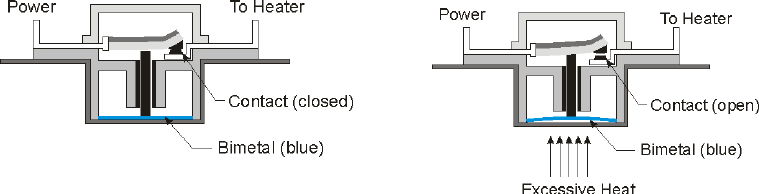
The temperature of the air inside the dryer drum is regulated/limited using different
thermostats. Simple thermostat models may contain only two terminals and are single-pole,
single-throw style switches. The high-limit thermostat is typically in series with the 240 VAC
power to the heater. When the high-limit thermostat is exposed to excessive heat, the bimetal
deflects, causing it to push on a plunger that disconnects one of the 240 VAC lines to the heater,
as shown in Figure 7. When the heater area cools, the bimetal returns, and the plunger retracts,
causing the contacts to close and reenergize the heater.
Figure 7. Cross-sectional View of Single-Pole, Single-Throw High-Limit Thermostat
Thermostats are also constructed as single-pole, double-throw style switches. These
thermostats can usually be identified by a third terminal, as shown in Figure 8. This type of
thermostat has one set of contacts normally open and another set closed. When the thermostat
activates after being exposed to excessive heat, the second set of contacts (normally open) would
close, while the contacts for the heater open.

15
Figure 8. Cross-sectional View of Single-Pole, Double-Throw High-Limit Thermostat
The second set of contacts on the high-limit thermostat could be used as an activation
signal to a Service Required indicator. The contacts would be connected to a latching circuit so
that, when the high-limit thermostat first activates, it would latch the signal, as shown in Figure
9. The signal would activate the Service Required indicator light and would continue to activate
the indicator even if the high-limit thermostat resets. Once the problem is corrected, the latch
could be reset manually, which would deactivate the Service Required light.
Figure 9. Incorporating a Service Required Indicator
The maintenance indicators would require monitoring two different conditions—the
number of dryer cycles and the status of the lint screen. There are many methods that could be
used to monitor the status of the lint screen. The difficulty may lie in finding a sensor that is not
susceptible to lint contamination. Monitoring a decrease in air flow from one side of the lint
screen is one method to determine excessive lint on the lint screen, as shown in Figure 11. A
comparator would look at the signals from each sensor and, if the difference exceeds a
predetermined threshold, it would activate the Clean Lint Filter indicator. When the sensors have

16
detected that the lint screen has been cleaned (air flow is adequate after the lint screen is
cleaned), the Clean Lint Filter indicator light would be reset to “off.”
The maintenance tasks of cleaning the duct and cleaning inside the cabinet are often
forgotten because the user generally does not look in these areas to observe the accumulation of
lint. An indicator light, which is activated after a set number of loads, may be a helpful visual
reminder that this task needs to be performed. Using a counter connected to the dryer’s start
button could keep track of the number of dryer operations, as shown in Figure 10. When the
counter has reached a manufacturer-set limit, the Clean Dryer Duct and Cabinet indicator would
activate. There may be a slight error in the count because not all start button activations
represent a complete cycle; but because there are so many other variables, such as size and type
of load, the trigger set count likely would represent a conservative maintenance interval.
Resetting the counter could be accomplished either manually, by using a reset button, or
automatically, when the dryer has been unplugged, because cleaning the cabinet and dryer duct
would require unplugging the unit.
Figure 10. Incorporating Clean Lint Filter and Clean Dryer Duct and Cabinet Indicators
17
8.0 CONCLUSION
Consumers report that they usually clean their clothes dryer lint filters; however, they
also report that they typically do not clean the ducting or inside the dryer cabinet. Failure to
clean ducts and airways is among the leading factors associated with clothes dryer fires. Lint can
begin to accumulate inside a dryer, even when the dryer’s lint screen has been cleaned after each
use and the dryer is properly exhausted. Lint accumulating inside the dryer cabinet, and in
contact with the heater, can potentially lead to a fire.
As seen in consumer-reported incidents, a dryer could be operating in an unfavorable
mode for an extended period of time until the situation escalates into a more hazardous scenario.
Clothes dryers commonly do not include any form of operating status indicators. Indicators that
remind consumers of maintenance tasks or warn that the clothes dryer is not operating normally,
could offer consumers valuable information that might improve clothes dryer safety.
Maintenance indicators could be used to remind consumers to clean inside the dryer
chassis and dryer duct. Counting dryer loads is one easy method that can be translated to an
indicator to remind consumers when a task needs to be performed—check and clean the exhaust
exit, exhaust duct, and inside the dryer cabinet. The specific number of times the dryer can run
before a check and cleaning task needs to be performed would be manufacturer and dryer design-
specific.
An “abnormal operations” indicator could provide consumers with information about a
potentially hazardous condition. Normally, clothes that do not dry may be the only indication to
a consumer that a dryer is not operating correctly. The dryer can enter into a high-limit cycling
mode from a number of conditions, such as an overloaded dryer, a blocked exhaust duct, or a
blocked lint screen. Feedback on the status of the high-limit thermostat would be a valuable
indicator that service needs to be performed on the dryer system.
Using indicators to tell the consumer that maintenance and service are required on the
clothes dryer can potentially reduce the number of fire-related incidents involving clothes dryers.
18
Bibliography
AHAM. (2002). AHAM Analysis of Industry Data on Clothes Dryer Fire Incidents. Washington DC: Association of
Home Appliance Manufacturers (AHAM).
Balci-Sinha, R. (2010). Consumer Opinion Forum, Survey #3 Clothes Dryer Maintenance. Directorate for
Engineering Sciences. Bethesda: US Consumer Product Safety Commission.
Belz, S. M., Robinson, G. S., & Casali, J. G. (December 1999). A New Class of Auditory Warning Signals for
Complex Systems: Auditory Icons. Human Factors: The Journal of the Human Factors and Ergonomics Society ,
608-618.
Braun, C. C., Holt, R. S., & Silver, N. C. (2001). Adding Consequence Information to Product Instructions: Changes
in Hazard Perceptions. In M. S. Wogalter, S. L. Young, & K. R. Laughery, Human Factors Perspectives on
Warnings. Volume 2.
Chan, A., & Ng, A. (2009). Perceptions of implied hazard for visual and auditory alerting signals. Safety Science ,
346-352.
Chowdhury, R., Greene, M., & Miller, D. (
2008). 2003-2005 Residential Fire Loss Estimates, U.S. National
Estimates of Fires, Deaths, Injuries, and Property Losses from Unintentional Fires. Directorate for Epidemiology.
Bethesda: US Consumer Product Safety Commission.
Defense, D. o. (1999). Design Criteria Standard Human Engineering. Retrieved March 19, 2010, from
http://www.safetycenter.navy.mil/instructions/OSH/MILSTD1472F.pdf
Defense, D. o. (1995). Handbook for Human Engineering Design Guidelines. Retrieved March 19, 2010, from
http://www.hf.faa.gov/docs/508/docs/milhdbk759C.pdf
Dingus, T. A., Hathaway, ,. J., & Hunn, B. P. (1991). A Most Critical Warning Variable: Two Demonstrations of the
Powerful Effects of Cost on Warning Compliance. Proceedings of the Human Factors Society 35th Annual Meeting.
Edworthy, J., & Adams, A. (1996). Warning Design: A Research Prospective.
Edworthy, J., & Hellier, E. (2000). Auditory Warnings in Noisy Environments. Noise Health , 27-39.
FEMA. (2007). Clothes Dryer Fires in Residential Buildings. Topical Fire Research Series , 7 (1), 6.
Freedman, M., Lerner, N., Zador, P., Singer, J., & Levi, S. (2009). Effectiveness and Acceptance of Enhanced Seat
Belt Reminder Systems: Characteristics of Optimal Reminder Systems. DOT HS 811 097.
Glendon, A. I., Clarke, S., & McKenna, E. F. (1995). Human safety and risk management.
Hall, J. J. (2009). Home Fires involving Clothes Dryers and Washing Machines. Fire Analysis and Research
Division. Quincy: National Fire Protection Association.
Laughery, K. R. (2006). Safety Communications: Warnings. Applied Ergonomics , 467-478.
Laughery, K. R., & Hammond, A. (1999). Overview. In M. S. Wogalter, D. M. DeJoy, & K. R. Laughery, Warnings
and Risk Communication.
Lee, A. (2003). Final report on Electric Clothes Dryers and Lint Ignition Characteristics. Directorate for
Engineering Sciences. Bethesda: US Consumer Product Safety Commission.
NAHB. (2007). Study of Life Expectancy of Home Components. Economics Group of NAHB. Washington DC:
National Association of Home Builders.
Papastavrou, J. D., & Lehto, M. R. (1996). Improving the effectiveness of warnings by increasing the
appropriateness of their information content: Some hypotheses about human compliance. Safety Science .
Rogers, W. A., Lamson, N., & Rousseau, G. K. (2000). Warning Research: An Integrative Perspective. Human
Factors .
Sanders, M. S., & McCormick, E. J. (1993). Human Factors in Engineering and Design.
Underwriters Laboratories Inc. (2009, March 20). UL 2158 Electric Clothes Dryers. Northbrook, Illinois.
Wogalter, M. S. (1998). Factors Influencing the Effectiveness of Warnings. In H. Zwaga, T. Boersema, & H.
Hoohhout, Visual Information For Everyday Use: Design And Research Perspectives.
Wogalter, M. S., Conzola, V. C., & Smith-Jackson, T. L. (2002). Research-Based Guidelines for Warning Design
and Evaluation. Applied Ergonomics , 219-230.
Wogalter, M. S., Rashid, R., Clarke, S. W., & Kalsher, M. J. (1991). Evaluating the Behavioral Effectiveness of a
Multi-Modal Voice Warning Sign in a Visually Cluttered Environment . Human Factors and Ergonomics Society
Annual Meeting Proceedings , 718-722.
Wogalter, M. S., Young, S., Brelsford, J. W., & Barlow, T. (1999). The relative contributions of injury severity and
likelihood information on hazard-risk judgments and warning compliance. Journal of Safety Research , 151-162.
Woodson, W. E. (1981). Human Factors Design Handbook. McGraw-Hill Inc.,US .

19
APPENDIX
Warnings aim to increase safety by reducing the incident rates, influencing people’s behavior in
ways that will improve safety, and guiding people to make informed decisions by providing information
about a hazard, its consequences, and how to take precautions (Laughery, 1999). Warnings should be
noticeable; the information presented should be understandable by its intended population; and the
message should be persuasive to motivate people to comply (Wogalter 1998).
When evaluating status indicators, it is important to consider the relevant human factors research.
Laughery (2006) noted that a cost-benefit tradeoff analysis, comparing the benefits of complying with the
warnings versus the cost of compliance (such as time, effort, or money), could be used in the decision-
making process. A number of research studies show that reducing cost of compliance increases the
overall compliance (Rogers et al., 2000). Dingus et al. (1991) concluded that the cost of compliance must
be very low to garner the highest possible compliance with the warning directions. CPSC staff’s
questionnaire on clothes dryer maintenance showed that the lower the cost, time, and/or difficulty of the
maintenance task, the higher the ratio of respondents who performed the maintenance activity (Balci-
Sinha, 2010). The simplest maintenance task is to clean the lint filter, and approximately 96 percent of all
respondents reported cleaning their clothes dryer lint filter at some time. It is not difficult to inspect the
exhaust exit if it is reachable from ground level, but the task requires more effort and time than cleaning
the lint filter. For this maintenance, approximately 71 percent of the respondents indicated that they
checked exhaust exits. The slot for the lint filter in most cases is too thin for a hand with a rag to reach in
and wipe up any accumulated lint. Using a vacuum requires more effort than simply removing the lint
from the filter. For this task, approximately 62 percent of the respondents cleaned the area under the lint
filter. Cleaning the exhaust duct and inside the dryer cabinet requires moving the dryer to access the
exhaust duct or the back of the dryer. These tasks require more time and effort. For these tasks, 38
percent and 20 percent of the respondents, respectively, cleaned the dryer ducts and inside the dryer
cabinet.
Status indicators can be provided in several different ways. Auditory warnings can be used to
call attention to a hazardous situation; these may be followed by a visual warning, which could include
more detailed information on the hazard (Wogalter et al., 2002).
A.1 Auditory Displays
Principles of Auditory Display
Sanders and McCormick (1993) cite the general principles of auditory display as compatibility
(i.e., signals matching to the learned or natural relationships of the users), approximation, dissociability
(i.e., easy to differentiate), parsimony (i.e., only the required amount of information), invariance, or
consistency. They suggest avoiding extremes of auditory dimensions; making sure that the intensity level
is not masked with ambient noise level; using interrupted or variable signals; and avoiding the auditory
channel overload. They recommend that the signals be tested with potential users, ensure that the new
signals do not contradict the old ones, and overlapping the old and new modes for a certain period until
people get accustomed to the new signals.
Edworthy and Adams (1996) list the effects of various pulse and burst signals on perceived
urgency. For pulses, a high fundamental frequency, random harmonics, no delayed harmonics, and a
regular amplitude envelope produces a more urgent message than a low fundamental frequency, regular
harmonics, delayed harmonics, and an amplitude envelope with a slow offset. For bursts, fast speed, four
repeating units, regular rhythm, speeding up, random pitch contour, large pitch range, atonal musical
structure produces a more urgent message than slow speed, nonrepeating units, in syncopated rhythm,

20
regular/slowing speeding change, down/up contour pitch, moderate pitch range, and resolved musical
structure.
A.2 Increasing Detectability of Auditory Signals
Several options include: increasing the intensity of the signal; presenting the signal for at least
0.5 second to 1 second; and composing the signal in four or more prominent frequency components in the
range from 1000 to 4000 Hz because complex sounds are more difficult to mask than simpler sounds.
Other recommendations are:
Use frequencies between 200 Hz and 5000 Hz, and preferably between 500 and 3000 Hz, because the
ear is most sensitive to this middle range.
Use frequencies below 1000 Hz when signals have to travel long distances (over 1000 ft), because
high frequencies do not travel as far.
Use frequencies below 500 Hz when signals “bend around” obstacles or pass through partitions.
Use a modulated signal (1 to 8 beeps per second, or warbling sounds varying from 1 to 3 times per
second), because it is different enough from normal sounds to demand attention.
Use signals with frequencies different from those that dominate the background noise.
MIL-HDBK-759C (Department of Defense, 1995) specifies the following in warning signals: Warning
signals should be used to alert personnel of immediate action required in hazardous or emergency
situations. These signals should alert personnel and transmit identifying or action signals. These
functions may be accommodated by either a two-element or single-element signal as appropriate to the
situation in consideration of the total acoustic signal environment. If a small set of warning signals are
used, the single-element signal would be preferred because this would provide the shortest reaction time.
Warning signals should consist of distinctive, complex sounds of exceptional attention-getting value and
be presented at a level of at least 20 dB (on the A-weighted scale) above the noise environment.
Examples of warning signals include fire alarms, collision alarms, and transit bells on cranes.
A.3 Signal and Warning Lights
Sizes of Lights
The luminance threshold depends on many factors, such as the field size, surround state of
adaptation, other viewing conditions, and possibly individual visual acuity. The lowest luminance of a
stimulus is dependent on the field size or degrees and minutes of an arc (one minutes of an arc is equal to
1/60 of a degree). Teichner and Krebs recommend minimum sizes of lights that can be detected 50
percent of the time under varying combinations of exposure time and luminance. As the field size
decreases, the brightness needs to increase to achieve the same luminance threshold. For exposure times
less than one second, the brightness and field size needs to increase to achieve minimum luminance
threshold.
It has been suggested to increase luminance values at least twice of those shown to ensure that the
target is detected 99 percent of the time (Sanders and McCormick, 1993).
MIL-STD-1472F (Department of Defense, 1999) specifies various color coding of lights that can
be used to address different scenarios and relay various messages to the operator. The color red is used
for emergency conditions (flashing and >=25mm) and malfunctions (flashing and >=13mm). The color
yellow is used for extreme caution (steady and >=25mm) and check (steady and >=13mm). The color
green is used for acceptable or ready (steady and >=13mm).

21
.
Colors of Lights
Background color and ambient illumination can interact to influence the ability of people to
detect and respond to lights of different colors. If a signal has good brightness contrast against a dark
background, and if the absolute level of brightness of the signal is high, the color of the signal is of
minimal importance in attracting attention. But with low signal-to-background brightness contrast, a red
signal has a marked advantage, followed by green, yellow, and white, in that order (Sanders and
McCormick, 1993).
Following are additional recommendations (Woodson, 1981):
Red: Alert the operator that the situation makes the system inoperative (e.g., an error, failure, or life-
threatening).
Yellow: Alert the operator to a situation in which caution, recheck, or delay is necessary. A condition
that, if not attended to, could lead to a dangerous situation.
Green: Indicates that equipment is operating satisfactorily.
White: Indicates status, a test in progress, which may imply neither success nor failure of system
conditions.
Blue: Has no standard meaning, except when it has been assigned a special significance within a
given operating system (e.g., blue ref light to show headlights on high beam setting in automobiles).
Flash Rate of Lights
The flash rate should be well below that at which a flashing light appears as a steady light (the
flicker fusion frequency), which is 24–30 per second. In this regard, the recommended flash rates of about
3 to 10 per second (with duration of at least 0.05 second) with equal intervals of light and dark would
attract attention. The range of 60–120 flashes per minute (1 to 2 per second) appears to be compatible
with human discrimination capabilities (Sanders & McCormick, 1993).
In some cases, different flash rates might be used to signify different things, but no more than
three different rates should be used to align with perceptual capabilities of people.
Chan and Ng (2009) investigated the perceived relative effectiveness of visual and auditory alerts.
They used color, flash rate, flash mode, and auditory alarm type as variables. Red color was ranked as the
highest hazard level, followed by blue and yellow. The perceived hazard level for a visual alert increased
with its flash rate. Multiple flashes (double or triple) were found to be more effective than single flash
mode. Regarding the auditory alarm effect, siren and security alarm indicated greater hazard than the
buzzer. The authors concluded than two-way interactions also should be taken into consideration while
designing alerts.
Wogalter et al. (1991b) examined the effects of a multimodal warning sign on compliance
behavior by studying variables such as pictorials, a voice warning, and a flashing probe light in cluttered
and noncluttered environments. The voice warning had a significant effect on compliance. The strobe
(with a duration of 2.2 milliseconds per flash with a peak illuminance of 200,000 lux
4
at 1.2 m) flashing at
8Hz, although it attracted attention, did not hold participants’ attention. Authors suggest that a brief voice
message can be used to capture attention and communicate the most important information in a concise
manner.
4
Lux is equal to one lumen per square meter, where lumen is the unit of luminous flux (rate at which light energy is
emitted from a source).
