INTRODUCTION
TO
CRYPTOGRAPHY
AND
NETWORK SECURITY
McGraw-Hill Forouzan Networking Series
Titles by Behrouz A. Forouzan:
Cryptography and Network Security
Data Communications and Networking
TCP/IP Protocol Suite
Local Area Networks
Business Data Communications

INTRODUCTION
TO
CRYPTOGRAPHY
AND
NETWORK SECURITY
Behrouz A. Forouzan

INTRODUCTION TO CRYPTOGRAPHY AND NETWORK SECURITY
Published by McGraw-Hill, a business unit of The McGraw-Hill Companies, Inc., 1221 Avenue
of the Americas, New York, NY 10020. Copyright © 2008 by The McGraw-Hill Companies, Inc.
All rights reserved. No part of this publication may be reproduced or distributed in any form or
by any means, or stored in a database or retrieval system, without the prior written consent of The
McGraw-Hill Companies, Inc., including, but not limited to, in any network or other electronic
storage or transmission, or broadcast for distance learning.
Some ancillaries, including electronic and print components, may not be available to customers
outside the United States.
This book is printed on acid-free paper.
1 2 3 4 5 6 7 8 9 0 DOC/DOC 0 9 8 7
ISBN 978–0–07–287022–0
MHID 0–07–287022–2
Publisher: Alan R. Apt
Executive Marketing Manager: Michael Weitz
Senior Project Manager: Sheila M. Frank
Senior Production Supervisor: Kara Kudronowicz
Associate Media Producer: Christina Nelson
Senior Designer: David W. Hash
Cover/Interior Designer: Rokusek Design
(USE) Cover Image: ©John Still/Photonica–Getty Images
Compositor: ICC Macmillan Inc.
Typeface: 10/12 Times Roman
Printer: R. R. Donnelley Crawfordsville, IN
Library of Congress Cataloging-in-Publication Data
Forouzan, Behrouz A.
Introduction to cryptography and network security / Behrouz A. Forouzan.—1st ed.
p. cm.
Includes index.
ISBN 978-0-07-287022-0—ISBN 0-07-287022-2
1. Computer networks–Security measures. 2. Cryptography. I. Title.
TK5105.59.F672 2008
005.8–dc22
2006052665
www.mhhe.com
To my beloved daughter and son-in-law, Satara and Shane.
B. Forouzan

vii
CONTENTS
Preface xxiii
Chapter 1 Introduction 1
1.1 SECURITY GOALS 2
Confidentiality 2
Integrity 3
Availability 3
1.2 ATTACKS 3
Attacks Threatening Confidentiality 3
Attacks Threatening Integrity 4
Attacks Threatening Availability 5
Passive Versus Active Attacks 5
1.3 SERVICES AND MECHANISM 6
Security Services 6
Security Mechanisms 7
Relation between Services and Mechanisms 8
1.4 TECHNIQUES 9
Cryptography 9
Steganography 10
1.5 THE REST OF THE BOOK 12
Part One: Symmetric-Key Encipherment 12
Part Two: Asymmetric-Key Encipherment 12
Part Three: Integrity, Authentication, and Key Management 12
Part Four: Network Security 12
1.6 RECOMMENDED READING 12
Books 12
WebSites 12
1.7 KEY TERMS 13
1.8 SUMMARY 13
1.9 PRACTICE SET 14
Review Questions 14
Exercises 14
Part 1 Symmetric-Key Encipherment 17
Chapter 2 Mathematics of Cryptography 19
2.1 INTEGER ARITHMETIC 20
Set of Integers 20
viii CONTENTS
Binary Operations 20
Integer Division 21
Divisibility 22
Linear Diophantine Equations 28
2.2 MODULAR ARITHMETIC 29
Modulo Operator 29
Set of Residues: Z
n
30
Congruence 30
Operations in Z
n
32
Inverses 35
Addition and Multiplication Tables 39
Different Sets for Addition and Multiplication 39
Two More Sets 40
2.3 MATRICES 40
Definitions 40
Operations and Relations 41
Determinant 43
Inverses 44
Residue Matrices 44
2.4 LINEAR CONGRUENCE 45
Single-Variable Linear Equations 45
Set of Linear Equations 46
2.5 RECOMMENDED READING 47
Books 47
WebSites 47
2.6 KEY TERMS 47
2.7 SUMMARY 48
2.8 PRACTICE SET 49
Review Questions 49
Exercises 49
Chapter 3 Traditional Symmetric-Key Ciphers 55
3.1 INTRODUCTION 56
Kerckhoff’s Principle 57
Cryptanalysis 57
Categories of Traditional Ciphers 60
3.2 SUBSTITUTION CIPHERS 61
Monoalphabetic Ciphers 61
Polyalphabetic Ciphers 69
3.3 TRANSPOSITION CIPHERS 80
Keyless Transposition Ciphers 81
Keyed Transposition Ciphers 82
Combining Two Approaches 83
3.4 STREAM AND BLOCK CIPHERS 87
Stream Ciphers 87
Block Ciphers 89
Combination 89
3.5 RECOMMENDED READING 90
Books 90
CONTENTS ix
WebSites 90
3.6 KEY TERMS 90
3.7 SUMMARY 91
3.8 PRACTICE SET 92
Review Questions 92
Exercises 92
Chapter 4 Mathematics of Cryptography 97
4.1 ALGEBRAIC STRUCTURES 98
Groups 98
Ring 104
Field 105
Summary 107
4.2 GF(2
n
) FIELDS 107
Polynomials 108
Using a Generator 114
Summary 117
4.3 RECOMMENDED READING 117
Books 117
WebSites 117
4.4 KEY TERMS 118
4.5 SUMMARY 118
4.6 PRACTICE SET 119
Review Questions 119
Exercises 119
Chapter 5 Introduction to Modern Symmetric-Key
Ciphers 123
5.1 MODERN BLOCK CIPHERS 124
Substitution or Transposition 125
Block Ciphers as Permutation Groups 125
Components of a Modern Block Cipher 128
S-Boxes 132
Product Ciphers 136
Two Classes of Product Ciphers 139
Attacks on Block Ciphers 143
5.2 MODERN STREAM CIPHERS 148
Synchronous Stream Ciphers 149
Nonsynchronous Stream Ciphers 154
5.3 RECOMMENDED READING 154
Books 154
WebSites 154
5.4 KEY TERMS 154
5.5 SUMMARY 155
5.6 PRACTICE SET 156
Review Questions 156
Exercises 157
x CONTENTS
Chapter 6 Data Encryption Standard (DES) 159
6.1 INTRODUCTION 159
History 159
Overview 160
6.2 DES STRUCTURE 160
Initial and Final Permutations 160
Rounds 163
Cipher and Reverse Cipher 167
Examples 173
6.3 DES ANALYSIS 175
Properties 175
Design Criteria 176
DES Weaknesses 177
6.4 MULTIPLE DES 181
Double DES 182
Triple DES 184
6.5 SECURITY OF DES 185
Brute-Force Attack 185
Differential Cryptanalysis 185
Linear Cryptanalysis 186
6.6 RECOMMENDED READING 186
Books 186
WebSites 186
6.7 KEY TERMS 186
6.8 SUMMARY 187
6.9 PRACTICE SET 187
Review Questions 187
Exercises 188
Chapter 7 Advanced Encryption Standard (AES) 191
7.1 INTRODUCTION 191
History 191
Criteria 192
Rounds 192
Data Units 193
Structure of Each Round 195
7.2 TRANSFORMATIONS 196
Substitution 196
Permutation 202
Mixing 203
Key Adding 206
7.3 KEY EXPANSION 207
Key Expansion in AES-128 208
Key Expansion in AES-192 and AES-256 212
Key-Expansion Analysis 212
7.4 CIPHERS 213
Original Design 213
Alternative Design 214
CONTENTS xi
7.5 EXAMPLES 216
7.6 ANALYSIS OF AES 219
Security 219
Implementation 219
Simplicity and Cost 220
7.7 RECOMMENDED READING 220
Books 220
WebSites 220
7.8 KEY TERMS 220
7.9 SUMMARY 220
7.10 PRACTICE SET 221
Review Questions 221
Exercises 222
Chapter 8 Encipherment Using Modern Symmetric-Key
Ciphers 225
8.1 USE OF MODERN BLOCK CIPHERS 225
Electronic Codebook (ECB) Mode 226
Cipher Block Chaining (CBC) Mode 228
Cipher Feedback (CFB) Mode 231
Output Feedback (OFB) Mode 234
Counter (CTR) Mode 236
8.2 USE OF STREAM CIPHERS 238
RC4 238
A5/1 242
8.3 OTHER ISSUES 244
Key Management 244
Key Generation 244
8.4 RECOMMENDED READING 245
Books 245
WebSites 245
8.5 KEY TERMS 245
8.6 SUMMARY 245
8.7 PRACTICE SET 246
Review Questions 246
Exercises 247
Part 2 Asymmetric-Key Encipherment 249
Chapter 9 Mathematics of Cryptography 251
9.1 PRIMES 251
Definition 251
Cardinality of Primes 252
Checking for Primeness 253
Euler’s Phi-Function 254
Fermat’s Little Theorem 256
Euler’s Theorem 257
Generating Primes 258
xii CONTENTS
9.2 PRIMALITY TESTING 260
Deterministic Algorithms 260
Probabilistic Algorithms 261
Recommended Primality Test 266
9.3 FACTORIZATION 267
Fundamental Theorem of Arithmetic 267
Factorization Methods 268
Fermat Method 269
Pollard p – 1 Method 270
Pollard rho Method 271
More Efficient Methods 272
9.4 CHINESE REMAINDER THEOREM 274
Applications 275
9.5 QUADRATIC CONGRUENCE 276
Quadratic Congruence Modulo a Prime 276
Quadratic Congruence Modulo a Composite 277
9.6 EXPONENTIATION AND LOGARITHM 278
Exponentiation 279
Logarithm 281
9.7 RECOMMENDED READING 286
Books 286
WebSites 286
9.8 KEY TERMS 286
9.9 SUMMARY 287
9.10 PRACTICE SET 288
Review Questions 288
Exercises 288
Chapter 10 Asymmetric-Key Cryptography 293
10.1 INTRODUCTION 293
Keys 294
General Idea 294
Need for Both 296
Trapdoor One-Way Function 296
Knapsack Cryptosystem 298
10.2 RSA CRYPTOSYSTEM 301
Introduction 301
Procedure 301
Some Trivial Examples 304
Attacks on RSA 305
Recommendations 310
Optimal Asymmetric Encryption Padding (OAEP) 311
Applications 314
10.3 RABIN CRYPTOSYSTEM 314
Procedure 315
Security of the Rabin System 317
10.4 ELGAMAL CRYPTOSYSTEM 317
ElGamal Cryptosystem 317
Procedure 317
CONTENTS xiii
Proof 319
Analysis 319
Security of ElGamal 320
Application 321
10.5 ELLIPTIC CURVE CRYPTOSYSTEMS 321
Elliptic Curves over Real Numbers 321
Elliptic Curves over GF( p) 324
Elliptic Curves over GF(2
n
) 326
Elliptic Curve Cryptography Simulating ElGamal 328
10.6 RECOMMENDED READING 330
Books 330
WebSites 330
10.7 KEY TERMS 331
10.8 SUMMARY 331
10.9 PRACTICE SET 333
Review Questions 333
Exercises 334
Part 3 Integrity, Authentication, and Key Management 337
Chapter 11 Message Integrity and Message Authentication 339
11.1 MESSAGE INTEGRITY 339
Document and Fingerprint 340
Message and Message Digest 340
Difference 340
Checking Integrity 340
Cryptographic Hash Function Criteria 340
11.2 RANDOM ORACLE MODEL 343
Pigeonhole Principle 345
Birthday Problems 345
Attacks on Random Oracle Model 347
Attacks on the Structure 351
11.3 MESSAGE AUTHENTICATION 352
Modification Detection Code 352
Message Authentication Code (MAC) 353
11.4 RECOMMENDED READING 357
Books 357
WebSites 357
11.5 KEY TERMS 357
11.6 SUMMARY 358
11.7 PRACTICE SET 358
Review Questions 358
Exercises 359
Chapter 12 Cryptographic Hash Functions 363
12.1 INTRODUCTION 363
Iterated Hash Function 363
Two Groups of Compression Functions 364
xiv CONTENTS
12.2 SHA-512 367
Introduction 367
Compression Function 372
Analysis 375
12.3 WHIRLPOOL 376
Whirlpool Cipher 377
Summary 384
Analysis 384
12.4 RECOMMENDED READING 384
Books 384
WebSites 384
12.5 KEY TERMS 385
12.6 SUMMARY 385
12.7 PRACTICE SET 386
Review Questions 386
Exercises 386
Chapter 13 Digital Signature 389
13.1 COMPARISON 390
Inclusion 390
Verification Method 390
Relationship 390
Duplicity 390
13.2 PROCESS 390
Need for Keys 391
Signing the Digest 392
13.3 SERVICES 393
Message Authentication 393
Message Integrity 393
Nonrepudiation 393
Confidentiality 394
13.4 ATTACKS ON DIGITAL SIGNATURE 395
Attack Types 395
Forgery Types 395
13.5 DIGITAL SIGNATURE SCHEMES 396
RSA Digital Signature Scheme 396
ElGamal Digital Signature Scheme 400
Schnorr Digital Signature Scheme 403
Digital Signature Standard (DSS) 405
Elliptic Curve Digital Signature Scheme 407
13.6 VARIATIONS AND APPLICATIONS 409
Variations 409
Applications 411
13.7 RECOMMENDED READING 411
Books 411
WebSites 411
13.8 KEY TERMS 412
CONTENTS xv
13.9 SUMMARY 412
13.10 PRACTICE SET 413
Review Questions 413
Exercises 413
Chapter 14 Entity Authentication 415
14.1 INTRODUCTION 415
Data-Origin Versus Entity Authentication 415
Verification Categories 416
Entity Authentication and Key Management 416
14.2 PASSWORDS 416
Fixed Password 416
One-Time Password 419
14.3 CHALLENGE-RESPONSE 421
Using a Symmetric-Key Cipher 421
Using Keyed-Hash Functions 423
Using an Asymmetric-Key Cipher 424
Using Digital Signature 425
14.4 ZERO-KNOWLEDGE 426
Fiat-Shamir Protocol 427
Feige-Fiat-Shamir Protocol 429
Guillou-Quisquater Protocol 429
14.5 BIOMETRICS 430
Components 431
Enrollment 431
Authentication 431
Techniques 432
Accuracy 433
Applications 434
14.6 RECOMMENDED READING 434
Books 434
WebSites 434
14.7 KEY TERMS 434
14.8 SUMMARY 435
14.9 PRACTICE SET 435
Review Questions 435
Exercises 436
Chapter 15 Key Management 437
15.1 SYMMETRIC-KEY DISTRIBUTION 438
Key-Distribution Center: KDC 438
Session Keys 439
15.2 KERBEROS 443
Servers 444
Operation 445
Using Different Servers 445
Kerberos Version 5 447
Realms 447
xvi CONTENTS
15.3 SYMMETRIC-KEY AGREEMENT 447
Diffie-Hellman Key Agreement 447
Station-to-Station Key Agreement 451
15.4 PUBLIC-KEY DISTRIBUTION 453
Public Announcement 453
Trusted Center 453
Controlled Trusted Center 454
Certification Authority 454
X.509 456
Public-Key Infrastructures (PKI) 458
15.5 RECOMMENDED READING 461
Books 461
WebSites 461
15.6 KEY TERMS AND CONCEPTS 462
15.7 SUMMARY 462
15.8 PRACTICE SET 463
Review Questions 463
Exercises 463
Part 4 Network Security 465
Chapter 16 Security at the Application Layer:
PGP and S/MIME 467
16.1 E-MAIL 467
E-mail Architecture 467
E-mail Security 469
16.2 PGP 470
Scenarios 470
Key Rings 472
PGP Certificates 475
Key Revocation 482
Extracting Information from Rings 482
PGP Packets 484
PGP Messages 490
Applications of PGP 492
16.3 S/MIME 492
MIME 492
S/MIME 498
Applications of S/MIME 502
16.4 RECOMMENDED READING 502
Books 502
WebSites 502
16.5 KEY TERMS 502
16.6 SUMMARY 503
16.7 EXERCISES 503
Review Questions 503
Exercises 504
CONTENTS xvii
Chapter 17 Security at the Transport Layer: SSL and TLS 507
17.1 SSL ARCHITECTURE 508
Services 508
Key Exchange Algorithms 509
Encryption/Decryption Algorithms 511
Hash Algorithms 512
Cipher Suite 512
Compression Algorithms 513
Cryptographic Parameter Generation 513
Sessions and Connections 515
17.2 FOUR PROTOCOLS 517
Handshake Protocol 518
ChangeCipherSpec Protocol 525
Alert Protocol 526
Record Protocol 526
17.3 SSL MESSAGE FORMATS 529
ChangeCipherSpec Protocol 530
Alert Protocol 530
Handshake Protocol 530
Application Data 537
17.4 TRANSPORT LAYER SECURITY 538
Version 539
Cipher Suite 539
Generation of Cryptographic Secrets 539
Alert Protocol 542
Handshake Protocol 543
Record Protocol 543
17.5 RECOMMENDED READING 545
Books 545
WebSites 545
17.6 KEY TERMS 545
17.7 SUMMARY 545
17.8 PRACTICE SET 546
Review Questions 546
Exercises 546
Chapter 18 Security at the Network Layer: IPSec 549
18.1 TWO MODES 550
Comparison 552
18.2 TWO SECURITY PROTOCOLS 552
Authentication Header (AH) 552
Encapsulating Security Payload (ESP) 554
IPv4 and IPv6 555
AH versus ESP 555
Services Provided by IPSec 555
18.3 SECURITY ASSOCIATION 557
Idea of Security Association 557
Security Association Database (SAD) 558
xviii CONTENTS
18.4 SECURITY POLICY 560
Security Policy Database 560
18.5 INTERNET KEY EXCHANGE (IKE) 563
Improved Diffie-Hellman Key Exchange 563
IKE Phases 566
Phases and Modes 566
Phase I: Main Mode 567
Phase I: Aggressive Mode 573
Phase II: Quick Mode 575
SA Algorithms 577
18.6 ISAKMP 578
General Header 578
Payloads 579
18.7 RECOMMENDED READING 588
Books 588
WebSites 588
18.8 KEY TERMS 588
18.9 SUMMARY 589
18.10 PRACTICE SET 589
Review Questions 589
Exercises 590
Appendix A ASCII 593
Appendix B Standards and Standard Organizations 595
B.1 INTERNET STANDARDS 595
Maturity Levels 595
Requirement Levels 597
Internet Administration 597
B.2 OTHER STANDARD ORGANIZATIONS 599
NIST 599
ISO 599
ITU-T 599
ANSI 600
IEEE 600
EIA 600
Appendix C TCP/IP Protocol Suite 601
C.1 LAYERS IN THE TCP/IP 602
Application Layer 602
Transport Layer 602
Network Layer 603
Data Link Layer 604
Physical Layer 604
C.2 ADDRESSING 604
Specific Address 604
Port Address 604
Logical Address 605
Physical Address 605
CONTENTS xix
Appendix D Elementary Probability 607
D.1 INTRODUCTION 607
Definitions 607
Probability Assignment 608
Axioms 609
Properties 609
Conditional Probability 609
D.2 RANDOM VARIABLES 610
Continuous Random Variables 610
Discrete Random Variables 610
Appendix E Birthday Problems 611
E.1 FOUR PROBLEMS 611
First Problem 611
Second Problem 612
Third Problem 612
Fourth Problem 613
E.2 SUMMARY 614
Appendix F Information Theory 615
F.1 MEASURING INFORMATION 615
F.2 ENTROPY 616
Maximum Entropy 616
Minimum Entropy 617
Interpretation of Entropy 617
Joint Entropy 617
Conditional Entropy 617
Other Relations 618
Perfect Secrecy 618
F.3 ENTROPY OF A LANGUAGE 619
Entropy of an Arbitrary Language 619
Entropy of the English Language 619
Redundancy 619
Unicity Distance 620
Appendix G List of Irreducible and Primitive Polynomials 621
Appendix H Primes Less Than 10,000 623
Appendix I Prime Factors of Integers Less Than 1000 627
Appendix J List of First Primitive Roots for
Primes Less Than 1000 631
Appendix K Random Number Generator 633
K.1 TRNG 633
xx CONTENTS
K.2 PRNG 634
Congruential Generators 634
Cryptosystem-Based Generators 636
Appendix L Complexity 639
L.1 COMPLEXITY OF AN ALGORITHM 639
Bit-Operation Complexity 639
L.2 COMPLEXITY OF A PROBLEM 643
Two Broad Categories 643
L.3 PROBABILISTIC ALGORITHMS 644
Monte Carlo Algorithms 644
Las Vegas Algorithms 644
Appendix M ZIP 645
M.1 LZ77 ENCODING 645
Compression 646
Decompression 647
Appendix N Differential and Linear Cryptanalysis of DES 651
N.1 DIFFERENTIAL CRYPTANALYSIS 651
Probabilistic Relations 651
Attack 653
Finding the Cipher Key 654
Security 654
N.2 LINEAR CRYPTANALYSIS 655
Linearity Relations 655
Attack 658
Security 658
Appendix O Simplified DES (S-DES) 659
O.1 S-DES STRUCTURE 659
Initial and Final Permutations 660
Rounds 660
Key Generation 663
O.2 CIPHER AND REVERSE CIPHER 664
Appendix P Simplified AES (S-AES) 667
P.1 S-AES STRUCTURE 667
Rounds 667
Data Units 668
Structure of Each Round 670
P.2 TRANSFORMATIONS 671
Substitution 671
Permutation 672
CONTENTS xxi
Mixing 673
Key Adding 674
P.3 KEY EXPANSION 675
Creation of Words in S-AES 675
P.4 CIPHERS 677
Appendix Q Some Proofs 679
Q.1 CHAPTER 2 679
Divisibility 679
Euclidean Algorithms 680
Congruence 681
Q.2 CHAPTER 9 682
Primes 682
Euler’s Phi-Function 683
Fermat’s Little Theorem 684
Euler’s Theorem 684
Fundamental Theorem of Arithmetic 685
Glossary 687
References 707
Index 709

xxiii
Preface
The Internet, as a worldwide communication network, has changed our daily life in
many ways. A new paradigm of commerce allows individuals to shop online. The
World Wide Web (WWW) allows people to share information. The E-mail technology
connect people in far-flung corners of the world. This inevitable evolution has also cre-
ated dependency on the Internet.
The Internet, as an open forum, has created some security problems. Confidential-
ity, integrity, and authentication are needed. People need to be sure that their Internet
communication is kept confidential. When they shop online, they need to be sure that
the vendors are authentic. When they send their transactions request to their banks, they
want to be certain that the integrity of the message is preserved.
Network security is a set of protocols that allow us to use the Internet comfortably
without worrying about security attacks. The most common tool for providing network
security is cryptography, an old technique that has been revived and adapted to network
security. This book first introduces the reader to the principles of cryptography and then
applies those principles to describe network security protocols.
Features of the Book
Several features of this text are designed to make it particularly easy for readers to
understand cryptography and network security.
Structure
This text uses an incremental approach to teaching cryptography and network security.
It assumes no particular mathematical knowledge, such as number theory or abstract
algebra. However, because cryptography and network security cannot be discussed
without some background in these areas of mathematics, these topics are discussed in
Chapters 2, 4, and 9. Readers who are familiar with these areas of mathematics can
ignore these chapters. Chapters 1 through 15 discuss cryptography. Chapters 16
through 18 discuss network security.
xxiv PREFACE
Visual Approach
This text presents highly technical subject matters without complex formulas by using a
balance of text and figures. More than 400 figures accompanying the text provide a visual
and intuitive opportunity for understanding the materials. Figures are particularly important
in explaining difficult cryptographic concepts and complex network security protocols.
Algorithms
Algorithms play an important role in teaching cryptography. To make the presentation
independent from any computer language, the algorithms have been given in
pseudocode that can be easily programmed in a modern language. At the website for
this text, the corresponding programs are available for download.
Highlighted Points
Important concepts are emphasized in highlighted boxes for quick reference and imme-
diate attention.
Examples
Each chapter presents a large number of examples that apply concepts discussed in the
chapter. Some examples merely show the immediate use of concepts and formulae;
some show the actual input/output relationships of ciphers; others give extra informa-
tion to better understand some difficult ideas.
Recommended Reading
At the end of each chapter, the reader will find a list of books for further reading.
Key Terms
Key terms appear in bold in the chapter text, and a list of key terms appear at the end of
each chapter. All key terms are also defined in the glossary at the end of the book.
Summary
Each chapter ends with a summary of the material covered in that chapter. The sum-
mary provides a brief overview of all the important points in the chapter.
Practice Set
At the end of each chapter, the students will find a practice set designed to reinforce and
apply salient concepts. The practice set consists of two parts: review questions and
exercises. The review questions are intended to test the reader’s first-level understand-
ing of the material presented in the chapter. The exercises require deeper understanding
of the material.
Appendices
The appendices provide quick reference material or a review of materials needed to
understand the concepts discussed in the book. Some discussions of mathematical topics
PREFACE xxv
are also presented in the appendices to avoid distracting those readers who are already
familiar with these materials.
Proofs
Mathematical facts are mentioned in the chapters without proofs to emphasize the results
of applying the facts. For those interested reader the proofs are given in Appendix Q.
Glossary and Acronyms
At the end of the text, the reader will find an extensive glossary and a list of acronyms.
Contents
After the introductory Chapter 1, the book is divided into four parts:
Part One: Symmetric-Key Encipherment
Part One introduces the symmetric-key cryptography, both traditional and modern. The
chapters in this part emphasize the use of symmetric-key cryptography in providing
secrecy. Part One includes Chapters 2 through 8.
Part Two: Asymmetric-Key Encipherment
Part Two discusses asymmetric-key cryptography. The chapters in this part show how
asymmetric-key cryptography can provide security. Part Two includes Chapters 9 and 10.
Part Three: Integrity, Authentication, and Key Management
Part Three shows how cryptographic hashing functions can provide other security ser-
vices, such as message integrity and authentication. The chapters in this part also show
how asymmetric-key and symmetric-key cryptography can complement each other.
Part Three includes Chapters 11 through 15.
Part Four: Network Security
Part Four shows how the cryptography discussed in Part One through Three can be used
to create network security protocols at three levels of the Internet networking model.
Part Four includes Chapters 16 to 18.
How to Use this Book
This book is written for both an academic and a professional audience. Interested pro-
fessionals can use it for self-guidance study. As a textbook, it can be used for a one-
semester or one-quarter course. The following are some guidelines.
❏ Parts one to three are strongly recommended.
❏ Part four is recommended if the course needs to move beyond cryptography and
enter the domain of network security. A course in networking is a prerequisite for
Part four.
xxvi PREFACE
Online Learning Center
The McGraw-Hill Online Learning Center contains much additional material related to
Cryptography and Network Security. Readers can access the site at www.mhhe.com/
forouzan. Professors and students can access lecture materials, such as Power Point
slides. The solutions to odd-numbered problems are provided to students, and profes-
sors can use a password to access the complete set of solutions. Additionally, McGraw-
Hill makes it easy to create a website for the course with an exclusive McGraw-Hill
product called PageOut. It requires no prior knowledge of HTML, no long hours, and
no design skills on your part. Instead, PageOut offers a series of templates. Simply fill
them with your course information and click on one of 16 designs. The process takes
under an hour and leaves you with a professionally designed website. Although Page-
Out offers “instant” development, the finished website provides powerful features. An
interactive course syllabus allows you to post content to coincide with your lectures, so
when students visit your PageOut website, your syllabus will direct them to compo-
nents of Forouzan’s Online Learning Center, or specific material of your own.
Acknowledgments
It is obvious that the development of a book of this scope needs the support of many
people.
Peer Review
The most important contribution to the development of a book such as this comes from
peer reviews. I cannot express my gratitude in words to the many reviewers who spent
numerous hours reading the manuscript and providing me with helpful comments
and ideas. I would especially like to acknowledge the contributions of the following
reviewers:
Kaufman, Robert, University of Texas, San Antonio
Kesidis, George, Penn State
Stephens, Brooke, U. of Maryland, Baltimore County
Koc, Cetin, Oregon State University
Uminowicz, Bill, Westwood College
Wang, Xunhua, James Madison University
Kak, Subhash, Louisiana State U.
Dunigan, Tom, U. of Tennessee, Knoxville
McGraw-Hill Staff
Special thanks go to the staff of McGraw-Hill. Alan Apt, publisher, proved how a profi-
cient publisher can make the impossible possible. Melinda Bilecki, the developmental
editor, gave me help whenever I needed it. Sheila Frank, project manager, guided me
through the production process with enormous enthusiasm. I also thank David Hash
in design, Kara Kudronowicz in production, and Wendy Nelson, the copy editor.
Behrouz A. Forouzan

1
CHAPTER 1
Introduction
Objectives
This chapter has several objectives:
❏ To define three security goals
❏ To define security attacks that threaten security goals
❏ To define security services and how they are related to the three security
goals
❏ To define security mechanisms to provide security services
❏ To introduce two techniques, cryptography and steganography, to
implement security mechanisms.
We are living in the information age. We need to keep information about
every aspect of our lives. In other words, information is an asset that has
a value like any other asset. As an asset, information needs to be secured
from attacks.
To be secured, information needs to be hidden from unauthorized
access (confidentiality), protected from unauthorized change (integrity),
and available to an authorized entity when it is needed (availability).
Until a few decades ago, the information collected by an organization
was stored on physical files. The confidentiality of the files was achieved
by restricting the access to a few authorized and trusted people in the orga-
nization. In the same way, only a few authorized people were allowed to
change the contents of the files. Availability was achieved by designating
at least one person who would have access to the files at all times.
With the advent of computers, information storage became electronic.
Instead of being stored on physical media, it was stored in computers. The
three security requirements, however, did not change. The files stored in

2 CHAPTER 1 INTRODUCTION
computers require confidentiality, integrity, and availability. The implemen-
tation of these requirements, however, is different and more challenging.
During the last two decades, computer networks created a revolution in
the use of information. Information is now distributed. Authorized people
can send and retrieve information from a distance using computer net-
works. Although the three above-mentioned requirementsconfidentiality,
integrity, and availabilityhave not changed, they now have some new
dimensions. Not only should information be confidential when it is stored
in a computer; there should also be a way to maintain its confidentiality
when it is transmitted from one computer to another.
In this chapter, we first discuss the three major goals of information
security. We then see how attacks can threaten these three goals. We then
discuss the security services in relation to these security goals. Finally we
define mechanisms to provide security services and introduce techniques
that can be used to implement these mechanisms.
1.1 SECURITY GOALS
Let us first discuss three security goals: confidentiality, integrity, and availability
(Figure 1.1).
Confidentiality
Confidentiality is probably the most common aspect of information security. We need
to protect our confidential information. An organization needs to guard against those
malicious actions that endanger the confidentiality of its information. In the military,
concealment of sensitive information is the major concern. In industry, hiding some
information from competitors is crucial to the operation of the organization. In bank-
ing, customers’ accounts need to be kept secret.
As we will see later in this chapter, confidentiality not only applies to the storage
of the information, it also applies to the transmission of information. When we send a
piece of information to be stored in a remote computer or when we retrieve a piece of
information from a remote computer, we need to conceal it during transmission.
Figure 1.1
Taxonomy of security goals
Security
Goals
AvailabilityIntegrity
Confidentiality

SECTION 1.2 ATTACKS 3
Integrity
Information needs to be changed constantly. In a bank, when a customer deposits or with-
draws money, the balance of her account needs to be changed. Integrity means that
changes need to be done only by authorized entities and through authorized mechanisms.
Integrity violation is not necessarily the result of a malicious act; an interruption in the
system, such as a power surge, may also create unwanted changes in some information.
Availability
The third component of information security is availability. The information created and
stored by an organization needs to be available to authorized entities. Information is use-
less if it is not available. Information needs to be constantly changed, which means it
must be accessible to authorized entities. The unavailability of information is just as
harmful for an organization as the lack of confidentiality or integrity. Imagine what would
happen to a bank if the customers could not access their accounts for transactions.
1.2 ATTACKS
Our three goals of securityconfidentiality, integrity, and availabilitycan be threatened
by security attacks. Although the literature uses different approaches to categorizing the
attacks, we will first divide them into three groups related to the security goals. Later, we
will divide them into two broad categories based on their effects on the system. Figure 1.2
shows the first taxonomy.
Attacks Threatening Confidentiality
In general, two types of attacks threaten the confidentiality of information: snooping
and traffic analysis.
Figure 1.2
Taxonomy of attacks with relation to security goals
Security Attacks
Threat to
confidentiality
Threat to integrity
Snooping
Traffic
analysis
Masquerading
Replaying
Repudiation
Modification
Denial of
service
Threat to
availability
4 CHAPTER 1 INTRODUCTION
Snooping
Snooping refers to unauthorized access to or interception of data. For example, a file
transferred through the Internet may contain confidential information. An unauthorized
entity may intercept the transmission and use the contents for her own benefit. To prevent
snooping, the data can be made nonintelligible to the intercepter by using encipherment
techniques discussed in this book.
Traffic Analysis
Although encipherment of data may make it nonintelligible for the intercepter, she can
obtain some other type information by monitoring online traffic. For example, she can
find the electronic address (such as the e-mail address) of the sender or the receiver. She
can collect pairs of requests and responses to help her guess the nature of transaction.
Attacks Threatening Integrity
The integrity of data can be threatened by several kinds of attacks: modification, mas-
querading, replaying, and repudiation.
Modification
After intercepting or accessing information, the attacker modifies the information to
make it beneficial to herself. For example, a customer sends a message to a bank to do
some transaction. The attacker intercepts the message and changes the type of transac-
tion to benefit herself. Note that sometimes the attacker simply deletes or delays the
message to harm the system or to benefit from it.
Masquerading
Masquerading, or spoofing, happens when the attacker impersonates somebody else.
For example, an attacker might steal the bank card and PIN of a bank customer and pre-
tend that she is that customer. Sometimes the attacker pretends instead to be the
receiver entity. For example, a user tries to contact a bank, but another site pretends that
it is the bank and obtains some information from the user.
Replaying
Replaying is another attack. The attacker obtains a copy of a message sent by a user and
later tries to replay it. For example, a person sends a request to her bank to ask for pay-
ment to the attacker, who has done a job for her. The attacker intercepts the message
and sends it again to receive another payment from the bank.
Repudiation
This type of attack is different from others because it is performed by one of the two
parties in the communication: the sender or the receiver. The sender of the message
might later deny that she has sent the message; the receiver of the message might later
deny that he has received the message.
An example of denial by the sender would be a bank customer asking her bank to
send some money to a third party but later denying that she has made such a request. An

SECTION 1.2 ATTACKS 5
example of denial by the receiver could occur when a person buys a product from a
manufacturer and pays for it electronically, but the manufacturer later denies having
received the payment and asks to be paid.
Attacks Threatening Availability
We mention only one attack threatening availability: denial of service.
Denial of Service
Denial of service (DoS) is a very common attack. It may slow down or totally interrupt
the service of a system. The attacker can use several strategies to achieve this. She might
send so many bogus requests to a server that the server crashes because of the heavy load.
The attacker might intercept and delete a server’s response to a client, making the client to
believe that the server is not responding. The attacker may also intercept requests from
the clients, causing the clients to send requests many times and overload the system.
Passive Versus Active Attacks
Let us now categorize the attacks into two groups: passive and active. Table 1.1 shows
the relationship between this and the previous categorization.
Passive Attacks
In a passive attack, the attacker’s goal is just to obtain information. This means that the
attack does not modify data or harm the system. The system continues with its normal
operation. However, the attack may harm the sender or the receiver of the message.
Attacks that threaten confidentialitysnooping and traffic analysisare passive
attacks. The revealing of the information may harm the sender or receiver of the mes-
sage, but the system is not affected. For this reason, it is difficult to detect this type of
attack until the sender or receiver finds out about the leaking of confidential informa-
tion. Passive attacks, however, can be prevented by encipherment of the data.
Active Attacks
An active attack may change the data or harm the system. Attacks that threaten the
integrity and availability are active attacks. Active attacks are normally easier to detect
than to prevent, because an attacker can launch them in a variety of ways.
Table 1.1
Categorization of passive and active attacks
Attacks Passive/Active Threatening
Snooping
Traffic analysis
Passive Confidentiality
Modification
Masquerading
Replaying
Repudiation
Active Integrity
Denial of service Active Availability

6 CHAPTER 1 INTRODUCTION
1.3 SERVICES AND MECHANISMS
The International Telecommunication Union-Telecommunication Standardization
Sector (ITU-T) (see Appendix B) provides some security services and some mechanisms
to implement those services. Security services and mechanisms are closely related because a
mechanism or combination of mechanisms are used to provide a service. Also, a mechanism
can be used in one or more services. We briefly discuss them here to give the general idea;
we will discuss them in detail in later chapters devoted to specific services or mechanisms.
Security Services
ITU-T (X.800) has defined five services related to the security goals and attacks we
defined in the previous sections. Figure 1.3 shows the taxonomy of those five common
services.
It is easy to relate one or more of these services to one or more of the security
goals. It is also easy to see that these services have been designed to prevent the secu-
rity attacks that we have mentioned.
Data Confidentiality
Data confidentiality is designed to protect data from disclosure attack. The service as
defined by X.800 is very broad and encompasses confidentiality of the whole message
or part of a message and also protection against traffic analysis. That is, it is designed to
prevent snooping and traffic analysis attack.
Data Integrity
Data integrity is designed to protect data from modification, insertion, deletion, and
replaying by an adversary. It may protect the whole message or part of the message.
Authentication
This service provides the authentication of the party at the other end of the line. In
connection-oriented communication, it provides authentication of the sender or receiver
Figure 1.3
Security services
Security
Services
Nonrepudiation
Access
control
Authentication
Data
integrity
Data
confidentiality
Anti-change
Anti-replay
Peer entity
Data origin
Proof of origin
Proof of delivery

SECTION 1.3 SERVICES AND MECHANISM 7
during the connection establishment (peer entity authentication). In connectionless com-
munication, it authenticates the source of the data (data origin authentication).
Nonrepudiation
Nonrepudiation service protects against repudiation by either the sender or the receiver
of the data. In nonrepudiation with proof of the origin, the receiver of the data can later
prove the identity of the sender if denied. In nonrepudiation with proof of delivery, the
sender of data can later prove that data were delivered to the intended recipient.
Access Control
Access control provides protection against unauthorized access to data. The term
access in this definition is very broad and can involve reading, writing, modifying, exe-
cuting programs, and so on.
Security Mechanisms
ITU-T (X.800) also recommends some security mechanisms to provide the security
services defined in the previous section. Figure 1.4 gives the taxonomy of these
mechanisms.
Encipherment
Encipherment, hiding or covering data, can provide confidentiality. It can also be used
to complement other mechanisms to provide other services. Today two techniques
cryptography and steganographyare used for enciphering. We will discuss these shortly.
Figure 1.4
Security mechanisms
Digital signature
Authentication exchange
Traffic padding
Routing control
Notarization
Access control
Data integrity
Encipherment
Security
Mechanisms
8 CHAPTER 1 INTRODUCTION
Data Integrity
The data integrity mechanism appends to the data a short checkvalue that has been
created by a specific process from the data itself. The receiver receives the data and the
checkvalue. He creates a new checkvalue from the received data and compares the
newly created checkvalue with the one received. If the two checkvalues are the same,
the integrity of data has been preserved.
Digital Signature
A digital signature is a means by which the sender can electronically sign the data and
the receiver can electronically verify the signature. The sender uses a process that
involves showing that she owns a private key related to the public key that she has
announced publicly. The receiver uses the sender’s public key to prove that the message
is indeed signed by the sender who claims to have sent the message.
Authentication Exchange
In authentication exchange, two entities exchange some messages to prove their iden-
tity to each other. For example, one entity can prove that she knows a secret that only
she is supposed to know.
Traffic Padding
Traffic padding means inserting some bogus data into the data traffic to thwart the
adversary’s attempt to use the traffic analysis.
Routing Control
Routing control means selecting and continuously changing different available routes
between the sender and the receiver to prevent the opponent from eavesdropping on a
particular route.
Notarization
Notarization means selecting a third trusted party to control the communication
between two entities. This can be done, for example, to prevent repudiation. The
receiver can involve a trusted party to store the sender request in order to prevent the
sender from later denying that she has made such a request.
Access Control
Access control uses methods to prove that a user has access right to the data or
resources owned by a system. Examples of proofs are passwords and PINs.
Relation between Services and Mechanisms
Table 1.2 shows the relationship between the security services and the security mecha-
nisms. The table shows that three mechanisms (encipherment, digital signature, and
authentication exchange) can be used to provide authentication. The table also shows

SECTION 1.4 TECHNIQUES 9
that encipherment mechanism may be involved in three services (data confidentiality,
data integrity, and authentication)
1.4 TECHNIQUES
Mechanisms discussed in the previous sections are only theoretical recipes to imple-
ment security. The actual implementation of security goals needs some techniques. Two
techniques are prevalent today: one is very general (cryptography) and one is specific
(steganography).
Cryptography
Some security mechanisms listed in the previous section can be implemented using cryp-
tography. Cryptography, a word with Greek origins, means “secret writing.” However,
we use the term to refer to the science and art of transforming messages to make them
secure and immune to attacks. Although in the past cryptography referred only to the
encryption and decryption of messages using secret keys, today it is defined as involv-
ing three distinct mechanisms: symmetric-key encipherment, asymmetric-key encipher-
ment, and hashing. We will briefly discuss these three mechanisms here.
Symmetric-Key Encipherment
In symmetric-key encipherment (sometimes called secret-key encipherment or secret-
key cryptography), an entity, say Alice, can send a message to another entity, say Bob, over
an insecure channel with the assumption that an adversary, say Eve, cannot understand the
contents of the message by simply eavesdropping over the channel. Alice encrypts the
message using an encryption algorithm; Bob decrypts the message using a decryption
algorithm. Symmetric-key encipherment uses a single secret key for both encryption and
decryption. Encryption/decryption can be thought of as electronic locking. In symmetric-
key enciphering, Alice puts the message in a box and locks the box using the shared secret
key; Bob unlocks the box with the same key and takes out the message.
Asymmetric-Key Encipherment
In asymmetric-key encipherment (sometimes called public-key encipherment or
public-key cryptography), we have the same situation as the symmetric-key encipher-
ment, with a few exceptions. First, there are two keys instead of one: one public key
Table 1.2 Relation between security services and security mechanisms
Security Service Security Mechanism
Data confidentiality Encipherment and routing control
Data integrity Encipherment, digital signature, data integrity
Authentication Encipherment, digital signature, authentication exchanges
Nonrepudiation Digital signature, data integrity, and notarization
Access control Access control mechanism
10 CHAPTER 1 INTRODUCTION
and one private key. To send a secured message to Bob, Alice first encrypts the mes-
sage using Bob’s public key. To decrypt the message, Bob uses his own private key.
Hashing
In hashing, a fixed-length message digest is created out of a variable-length message.
The digest is normally much smaller than the message. To be useful, both the message
and the digest must be sent to Bob. Hashing is used to provide checkvalues, which were
discussed earlier in relation to providing data integrity.
Steganography
Although this book is based on cryptography as a technique for implementing secu-
rity mechanisms, another technique that was used for secret communication in the
past is being revived at the present time: steganography. The word steganography,
with origin in Greek, means “covered writing,” in contrast with cryptography, which
means “secret writing.” Cryptography means concealing the contents of a message by
enciphering; steganography means concealing the message itself by covering it with
something else.
Historical Use
History is full of facts and myths about the use of steganography. In China, war mes-
sages were written on thin pieces of silk and rolled into a small ball and swallowed by
the messenger. In Rome and Greece, messages were carved on pieces of wood, that
were later dipped into wax to cover the writing. Invisible inks (such as onion juice or
ammonia salts) were also used to write a secret message between the lines of the cover-
ing message or on the back of the paper; the secret message was exposed when the
paper was heated or treated with another substance.
In recent times other methods have been devised. Some letters in an innocuous
message might be overwritten in a pencil lead that is visible only when exposed to light
at an angle. Null ciphers were used to hide a secret message inside an innocuous simple
message. For example, the first or second letter of each word in the covering message
might compose a secret message. Microdots were also used for this purpose. Secret
messages were photographed and reduced to a size of a dot (period) and inserted into
simple cover messages in place of regular periods at the end of sentences.
Modern Use
Today, any form of data, such as text, image, audio, or video, can be digitized, and it is
possible to insert secret binary information into the data during digitization process.
Such hidden information is not necessarily used for secrecy; it can also be used to pro-
tect copyright, prevent tampering, or add extra information.
Text Cover The cover of secret data can be text. There are several ways to insert
binary data into an innocuous text. For example, we can use single space between
words to represent the binary digit 0 and double space to represent binary digit 1. The
following short message hides the 8-bit binary representation of the letter A in ASCII
code (01000001).

SECTION 1.4 TECHNIQUES 11
In the above message there are two spaces between the “book” and “is” and between
the “not” and “steganography”. Of course, sophisticated software can insert spaces that
differ only slightly to hide the code from immediate recognition.
Another, more efficient method, is to use a dictionary of words organized accord-
ing to their grammatical usages. We can have a dictionary containing 2 articles, 8 verbs,
32 nouns, and 4 prepositions. Then we agree to use cover text that always use sentences
with the pattern article-noun-verb-article-noun. The secret binary data can be divided
into 16-bit chunks. The first bit of binary data can be represented by an article (for exam-
ple, 0 for a and 1 for the). The next five bits can be represented by a noun (subject of the
sentence), the next four bits can be represented by a verb, the next bit by the second
article, and the last five bits by another noun (object). For example, the secret data “Hi”,
which is 01001000 01001001 in ASCII, could be a sentence like the following:
This is a very trivial example. The actual approach uses more sophisticated design
and a variety of patterns.
Image Cover Secret data can also be covered under a color image. Digitized images
are made of pixels (picture elements), in which normally each pixel uses 24 bits (three
bytes). Each byte represents one of the primary colors (red, green, or blue). We can there-
fore have 2
8
different shades of each color. In a method called LSB (least significant bit),
the least significant bit of each byte is set to zero. This may make the image a little bit
lighter in some areas, but this is not normally noticed. Now we can hide a binary data in
the image by keeping or changing the least significant bit. If our binary digit is 0, we keep
the bit; if it is 1, we change the bit to 1. In this way, we can hide a character (eight ASCII
bits) in three pixels. For example, the following three pixels can represent the letter M.
Of course, more sophisticated approaches are used these days.
Other Covers Other covers are also possible. The secret message, for example,
can be covered under audio (sound and music) and video. Both audio and video are
compressed today; the secret data can be embedded during or before the compres-
sion. We leave the discussion of these techniques to more specialized books in
steganography.
This book is mostly about cryptography, not steganography.
0 1 0 0 0 0 1
A friend called a doctor.
0 10010 0001 0 01001
01010011 10111100 01010101
01011110
10111100 01100101
01111110 01001010 00010101

12 CHAPTER 1 INTRODUCTION
1.5 THE REST OF THE BOOK
The rest of this book is divided into four parts.
Part One: Symmetric-Key Encipherment
The chapters in Part One discuss encipherment, both classic and modern, using sym-
metric-key cryptography. These chapters show how the first goal of security can be
implemented using this technique.
Part Two: Asymmetric-Key Encipherment
The chapters in Part Two discuss encipherment using asymmetric-key cryptography.
These chapters also show how the first goal of the security can be implemented using
this technique.
Part Three: Integrity, Authentication, and Key Management
The chapters in Part Three introduce the third application of cryptographyhashing
and show how it can be combined with the materials discussed in Part I and II for
implementing the second goal of security.
Part Four: Network Security
The chapters in Part Four show how the methods learned in the first three parts of the
book can be combined to create network security using the Internet model.
1.6 RECOMMENDED READING
For more details about subjects discussed in this chapter, the following books and web-
sites are good places to start. The items enclosed in brackets refer to the reference list at
the end of the book.
Books
Several books discuss security goals, attacks, and mechanisms. We recommend [Bis05]
and [Sta06].
WebSites
The following websites give more information about topics discussed in this chapter.
http://www.faqs.org/rfcs/rfc2828.html
fag.grm.hia.no/IKT7000/litteratur/paper/x800.pdf

SECTION 1.8 SUMMARY 13
1.7 KEY TERMS
1.8 SUMMARY
❏ Three general goals have been defined for security: confidentiality, integrity, and
availability.
❏ Two types of attacks threaten the confidentiality of information: snooping and traffic
analysis. Four types of attacks can threaten the integrity of information: modifica-
tion, masquerading, replaying, and repudiation. Denial-of-service attacks threaten
the availability of information.
❏ Some organizations involved in data communication and networking, such as
ITU-T or the Internet, have defined several security services that are related to
the security goals and security attacks. This chapter discussed five common secu-
rity services: data confidentiality, data integrity, authentication, nonrepudiation,
and access control.
❏ ITU-T also recommends some mechanisms to provide security. We discussed
eight of these mechanisms: encipherment, data integrity, digital signature,
authentication exchange, traffic padding, routing control, notarization, and access
control.
access control masquerading
active attack modification
asymmetric-key encipherment nonrepudiation
authentication notarization
authentication exchange passive attack
availability private key
confidentiality public key
cryptography replaying
data confidentiality repudiation
data integrity routing control
decryption secret key
denial of service security attacks
digital signature security goals
encipherment security mechanisms
encryption snooping
hashing steganography
integrity symmetric-key encipherment
International Telecommunication Union-
Telecommunication Standardization
Sector (ITU-T)
traffic analysis
traffic padding

14 CHAPTER 1 INTRODUCTION
❏ There are two techniquescryptography and steganographythat can imple-
ment some or all of the mechanisms. Cryptography or “secret writing” involves
scrambling a message or creating a digest of the message. Steganography or
“covered writing” means concealing the message by covering it with some-
thing else.
1.9 PRACTICE SET
Review Questions
1. Define the three security goals.
2. Distinguish between passive and active security attacks. Name some passive attacks.
Name some active attacks.
3. List and define five security services discussed in this chapter.
4. Define eight security mechanisms discussed in this chapter.
5. Distinguish between cryptography and steganography.
Exercises
6. Which security service(s) are guaranteed when using each of the following methods
to send mail at the post office?
a. Regular mail
b. Regular mail with delivery confirmation
c. Regular mail with delivery and recipient signature
d. Certified mail
e. Insured mail
f. Registered mail
7. Define the type of security attack in each of the following cases:
a. A student breaks into a professor’s office to obtain a copy of the next day’s test.
b. A student gives a check for $10 to buy a used book. Later she finds that the
check was cashed for $100.
c. A student sends hundreds of e-mails per day to another student using a phony
return e-mail address.
8. Which security mechanism(s) are provided in each of the following cases?
a. A school demands student identification and a password to let students log into
the school server.
b. A school server disconnects a student if she is logged into the system for more
than two hours.
c. A professor refuses to send students their grades by e-mail unless they provide
student identification they were preassigned by the professor.
d. A bank requires the customer’s signature for a withdrawal.
SECTION 1.9 PRACTICE SET 15
9. Which technique (cryptography or steganography) is used in each of the following
cases for confidentiality?
a. A student writes the answers to a test on a small piece of paper, rolls up the
paper, and inserts it in a ball-point pen, and passes the pen to another student.
b. To send a message, a spy replaces each character in the message with a symbol
that was agreed upon in advance as the character’s replacement.
c. A company uses special ink on its checks to prevent forgeries.
d. A graduate student uses watermarks to protect her thesis, which is posted on
her website.
10. What type of security mechanism(s) are provided when a person signs a form he has
filled out to apply for a credit card?

PART
1
Symmetric-Key Encipherment
In Chapter 1, we saw that cryptography provides three techniques: symmetric-key
ciphers, asymmetric-key ciphers, and hashing. Part One is devoted to symmetric-key
ciphers. Chapters 2 and 4 review the mathematical background necessary for under-
standing the rest of the chapters in this part. Chapter 3 explores the traditional ciphers
used in the past. Chapters 5, 6, and 7 explain modern block ciphers that are used
today. Chapter 8 shows how modern block and stream ciphers can be used to enci-
pher long messages.
Chapter 2: Mathematics of Cryptography: Part I
Chapter 2 reviews some mathematical concepts needed to understand the next
few chapters. It discusses integer and modular arithmetic, matrices, and congruence
relations.
Chapter 3: Traditional Symmetric-Key Ciphers
Chapter 3 introduces traditional symmetric-key ciphers. Although these ciphers are not
used today, they are the foundation of modern symmetric-key ciphers. This chapter
emphasizes the two categories of traditional ciphers: substitution ciphers and transposi-
tion ciphers. It also introduces the concepts of stream ciphers and block ciphers.
Chapter 4: Mathematics of Cryptography: Part II
Chapter 4 is another review of mathematics needed to understand the contents of the sub-
sequent chapters. It reviews some algebraic structures, such as groups, rings, and finite
fields, which are used in modern block ciphers.
Chapter 5: Introduction to Modern Symmetric-Key Ciphers
Chapter 5 is an introduction to modern symmetric-key ciphers. Understanding the indi-
vidual elements used in modern symmetric-key ciphers paves the way to a better under-
standing and analysis of modern ciphers. This chapter introduces components of block
ciphers such as P-boxes and S-boxes. It also distinguishes between two classes of product
ciphers: Feistel and non-Feistel ciphers.

18 PART 1 SYMMETRIC-KEY ENCIPHERMENT
Chapter 6: Data Encryption Standard (DES)
Chapter 6 uses the elements defined in Chapter 5 to discuss and analyze one of the com-
mon symmetric-key ciphers used today, the Data Encryption Standard (DES). The
emphasis is on how DES uses 16 rounds of Feistel ciphers.
Chapter 7: Advanced Encryption Standard (AES)
Chapter 7 shows how some algebraic structures discussed in Chapter 4 and some ele-
ments discussed in Chapter 5 can create a very strong cipher, the Advanced Encryption
Standard (AES). The emphasis is on how the algebraic structures discussed in Chapter 4
achieve the AES security goals.
Chapter 8: Encipherment Using Modern Symmetric-Key Ciphers
Chapter 8 shows how modern block and stream ciphers can actually be used to encipher
long messages. It explains five modes of operation designed to be used with modern
block ciphers. It also introduces two stream ciphers used for real-time processing of data.

19
CHAPTER 2
Mathematics of Cryptography
Part I: Modular Arithmetic, Congruence,
and Matrices
Objectives
This chapter is intended to prepare the reader for the next few chapters in
cryptography. The chapter has several objectives:
❏ To review integer arithmetic, concentrating on divisibility and find-
ing the greatest common divisor using the Euclidean algorithm
❏ To understand how the extended Euclidean algorithm can be used to
solve linear Diophantine equations, to solve linear congruent equa-
tions, and to find the multiplicative inverses
❏ To emphasize the importance of modular arithmetic and the modulo
operator, because they are extensively used in cryptography
❏ To emphasize and review matrices and operations on residue matri-
ces that are extensively used in cryptography
❏ To solve a set of congruent equations using residue matrices
Cryptography is based on some specific areas of mathematics, including
number theory, linear algebra, and algebraic structures. In this chapter, we
discuss only the topics in the above areas that are needed to understand the
contents of the next few chapters. Readers who are familiar with these top-
ics can skip this chapter entirely or partially. Similar chapters are provided
throughout the book when needed. Proofs of theorems and algorithms
have been omitted, and only their applications are shown. The interested
reader can find proofs of the theorems and algorithms in Appendix Q.
Proofs of theorems and algorithms discussed in this chapter can be found
in Appendix Q.

20 CHAPTER 2 MATHEMATICS OF CRYPTOGRAPHY
2.1 INTEGER ARITHMETIC
In integer arithmetic, we use a set and a few operations. You are familiar with this set
and the corresponding operations, but they are reviewed here to create a background for
modular arithmetic.
Set of Integers
The set of integers, denoted by Z, contains all integral numbers (with no fraction) from
negative infinity to positive infinity (Figure 2.1).
Binary Operations
In cryptography, we are interested in three binary operations applied to the set of integers.
A binary operation takes two inputs and creates one output. Three common binary oper-
ations defined for integers are addition, subtraction, and multiplication. Each of these
operations takes two inputs (a and b) and creates one output (c) as shown in Figure 2.2.
The two inputs come from the set of integers; the output goes into the set of integers.
Note that division does not fit in this category because, as we will see shortly, it
produces two outputs instead of one.
Example 2.1
The following shows the results of the three binary operations on two integers. Because each
input can be either positive or negative, we can have four cases for each operation.
Figure 2.1
The set of integers
Figure 2.2
Three binary operations for the set of integers
Add:
5 + 9 = 14 (−5) + 9 = 4 5 + (−9) = −4 (−5) + (−9) = −14
Subtract: 5 − 9 = −4 (−5) − 9 = −14 5 − (−9) = 14 (−5) − (−9) = +4
Multiply: 5 × 9 = 45
(−5) × 9 = −45
5 × (−9) = −45
(−5) × (−9) = 45
Z = { . . . , −2, −1, 0, 1, 2, . . . }
Z = { . . . , −2, −1, 0, 1, 2, . . . }
Z = { . . . , −2, −1, 0, 1, 2, . . . }
a b
c
Operation
+ ×−

SECTION 2.1 INTEGER ARITHMETIC 21
Integer Division
In integer arithmetic, if we divide a by n, we can get q and r. The relationship between
these four integers can be shown as
In this relation, a is called the dividend; q, the quotient; n, the divisor; and r, the
remainder. Note that this is not an operation, because the result of dividing a by n is
two integers, q and r. We can call it division relation.
Example 2.2
Assume that a
=
255 and n
=
11. We can find q
=
23 and r
=
2 using the division algorithm we
have learned in arithmetic as shown in Figure 2.3.
Most computer languages can find the quotient and the remainder using language-
specific operators. For example, in the C language, the operator / can find the quotient
and the operator % can find the remainder.
Two Restrictions
When we use the above division relationship in cryptography, we impose two restric-
tions. First, we require that the divisor be a positive integer (n > 0). Second, we require
that the remainder be a nonnegative integer (r ≥ 0). Figure 2.4 shows this relationship
with the two above-mentioned restrictions.
a ==
==
q ××
××
n ++
++
r
Figure 2.3
Example 2.2, finding the quotient and the remainder
Figure 2.4
Division algorithm for integers
2 5 5 1 1
2 2
3 5
3 3
2
2 3
q
a
r
n
n
(positive)
r
(nonnegative)
Z = { . . . , −2, −1, 0, 1, 2, . . . }
Z = { . . . , −2, −1, 0, 1, 2, . . . }
q
a = q × n + r
a

22 CHAPTER 2 MATHEMATICS OF CRYPTOGRAPHY
Example 2.3
When we use a computer or a calculator, r and q are negative when a is negative. How can we
apply the restriction that r needs to be positive? The solution is simple, we decrement the value of
q by 1 and we add the value of n to r to make it positive.
We have decremented −23 to become −24 and added 11 to −2 to make it 9. The above relation
is still valid.
The Graph of the Relation
We can show the above relation with the two restrictions on n and r using two graphs in
Figure 2.5. The first one shows the case when a is positive; the second when a is negative.
Starting from zero, the graph shows how we can reach the point representing the
integer a on the line. In case of a positive a, we need to move q × n units to the right and
then move extra r units in the same direction. In case of a negative a, we need to move
(q − 1) × n units to the left (q is negative in this case) and then move r units in the oppo-
site direction. In both cases the value of r is positive.
Divisibility
Let us briefly discuss divisibility, a topic we often encounter in cryptography. If a is not
zero and we let r = 0 in the division relation, we get
We then say that n divides a (or n is a divisor of a). We can also say that a is divis-
ible by n. When we are not interested in the value of q, we can write the above relation-
ship as a|n. If the remainder is not zero, then n does not divide a and we can write the
relationship as a n.
Example 2.4
a. The integer 4 divides the integer 32 because 32 = 8 × 4. We show this as 4|32.
b. The number 8 does not divide the number 42 because 42 = 5 × 8 + 2. There is a remainder, the
number 2, in the equation. We show this as 8
42.
−255 = (−23 × 11) + (–2) ↔ −255 = (−24 × 11) + 9
Figure 2.5 Graph of division algorithm
a ==
==
q ××
××
n
0 n 2n qn a
Case of
positive a
Case of
negative a
0
−n−2n
qn
(q − 1)n
a
r
r

SECTION 2.1 INTEGER ARITHMETIC 23
Example 2.5
a. We have 13|78, 7|98, −6|24, 4|44, and 11|(−33).
b. We have 13 27, 7 50, −6 23, 4 41, and 11 (−32).
Properties
Following are several properties of divisibility. The interested reader can check Appen-
dix Q for proofs.
Example 2.6
a. Since 3|15 and 15|45, according to the third property, 3|45.
b. Since 3|15 and 3|9, according to the fourth property, 3|(15 × 2 + 9 × 4), which means 3|66.
All Divisors
A positive integer can have more than one divisor. For example, the integer 32 has six
divisors: 1, 2, 4, 8, 16, and 32. We can mention two interesting facts about divisors of
positive integers:
Greatest Common Divisor
One integer often needed in cryptography is the greatest common divisor of two posi-
tive integers. Two positive integers may have many common divisors, but only one
greatest common divisor. For example, the common divisors of 12 and 140 are 1, 2, and 4.
However, the greatest common divisor is 4. See Figure 2.6.
Property 1: if a|1, then a = ±1.
Property 2: if a|b and b|a, then a =
±b.
Property 3: if a|b and b|c, then a|c.
Property 4: if a|b and a|c, then a|(m
× b + n × c), where m and n are arbitrary integers.
Fact 1: The integer 1 has only one divisor, itself.
Fact 2: Any positive integer has at least two divisors, 1 and itself (but it can have more).
Figure 2.6 Common divisors of two integers
Divisors of 140
Common Divisors
of 140 and 12
Divisor of 12
1
3
2
6
4
12
7
5
35
14
10
70
28
20
140

24 CHAPTER 2 MATHEMATICS OF CRYPTOGRAPHY
Euclidean Algorithm
Finding the greatest common divisor (gcd) of two positive integers by listing all com-
mon divisors is not practical when the two integers are large. Fortunately, more than
2000 years ago a mathematician named Euclid developed an algorithm that can find the
greatest common divisor of two positive integers. The Euclidean algorithm is based
on the following two facts (see Appendix Q for the proof):
The first fact tells us that if the second integer is 0, the greatest common divisor is
the first one. The second fact allows us to change the value of a, b until b becomes 0.
For example, to calculate the gcd (36, 10), we can use the second fact several times and
the first fact once, as shown below.
In other words, gcd (36, 10) = 2, gcd (10, 6) = 2, and so on. This means that instead
of calculating gcd (36, 10), we can find gcd (2, 0). Figure 2.7 shows how we use the
above two facts to calculate gcd (a, b).
We use two variables, r
1
and r
2
,
to hold the changing values during the process of
reduction. They are initialized to a and b. In each step, we calculate the remainder of
r
1
divided by r
2
and store the result in the variable r. We then replace r
1
by r
2
and r
2
by r.
The steps are continued until r
2
becomes 0. At this moment, we stop. The gcd (a, b) is r
1
.
The greatest common divisor of two positive integers is the largest integer that can
divide both integers.
Fact 1: gcd (a, 0) = a
Fact 2: gcd (a, b) = gcd (b, r), where r is the remainder of dividing a by b
gcd (36, 10) = gcd (10, 6) = gcd (6, 4) = gcd (4, 2) = gcd (2, 0) = 2
Figure 2.7 Euclidean algorithm
b. Algorithm a. Process
r
1
= a r
2
= b
r
r
gcd (a , b) = r
1
r
2
r
1
r
2
r
1
0
r
1
0
}
{
while (r
2
> 0)
(Initialization)
gcd (a, b) ← r
1
q ← r
1
/ r
2
;
r
1
← a; r
2
← b;
r
1
← r
2
; r
2
← r;
r ← r
1
− q × r
2
;

SECTION 2.1 INTEGER ARITHMETIC 25
Example 2.7
Find the greatest common divisor of 2740 and 1760.
Solution
We apply the above procedure using a table. We initialize r
1
to 2740 and r
2
to 1760. We have also
shown the value of q in each step. We have gcd (2740, 1760) = 20.
Example 2.8
Find the greatest common divisor of 25 and 60.
Solution
We chose this particular example to show that it does not matter if the first number is smaller than
the second number. We immediately get our correct ordering. We have gcd (25, 65) = 5.
The Extended Euclidean Algorithm
Given two integers a and b, we often need to find other two integers, s and t, such that
The extended Euclidean algorithm can calculate the gcd (a, b) and at the same time
calculate the value of s and t. The algorithm and the process is shown in Figure 2.8.
As shown in Figure 2.8, the extended Euclidean algorithm uses the same number of
steps as the Euclidean algorithm. However, in each step, we use three sets of calculations
and exchanges instead of one. The algorithm uses three sets of variables, r’s, s’s, and t’s.
When gcd (a, b) = 1, we say that a and b are relatively prime.
q r
1
r
2
r
1 2740 1760 980
1 1760 980 780
1 980 780 200
3 780 200 180
1 200 180 20
9 180 20 0
20 0
q r
1
r
2
r
0 25 60 25
2 60 25 10
2 25 10 5
2 10 5 0
5 0
s × a + t × b = gcd (a, b)

26 CHAPTER 2 MATHEMATICS OF CRYPTOGRAPHY
In each step, r
1
, r
2
, and r have the same values in the Euclidean algorithm. The variables r
1
and r
2
are initialized to the values of a and b, respectively. The variables s
1
and s
2
are initial-
ized to 1 and 0, respectively. The variables t
1
and t
2
are initialized to 0 and 1, respectively.
The calculations of r, s, and t are similar, with one warning. Although r is the remainder of
dividing r
1
by r
2
, there is no such relationship between the other two sets. There is only one
quotient, q, which is calculated as r
1
/r
2
and used for the other two calculations.
Example 2.9
Given a = 161 and b = 28, find gcd (a, b) and the values of s and t.
Solution
Figure 2.8 Extended Euclidean algorithm
r = r
1
− q × r
2
s = s
1
− q × s
2
t = t
1
− q × t
2
b. Algorithm
a. Process
r
1
= a r
2
= b
r
r
gcd (a , b) = r
1
r
2
r
1
r
2
r
1
0
r
1
0
s
1
= 1 s
2
= 0
s
s
s = s
1
s
2
s
1
s
2
s
1
s
s
1
s
2
t
1
= 0 t
2
= 1
t
t
t = t
1
t
2
t
1
t
2
t
1
t
t
1
t
2
}
(Initialization)
(Updating r’s)
r
1
← a; r
2
← b;
s
1
← 1; s
2
← 0;
t
1
← 0; t
2
← 1;
{
while (r
2
> 0)
q ← r
1
/ r
2
;
r
1
← r
2
; r
2
← r;
r ← r
1
− q × r
2
;
(Updating s’s)
s
1
← s
2
; s
2
← s;
s ← s
1
− q × s
2
;
(Updating t’s)
t
1
← t
2
; t
2
← t;
t ← t
1
− q × t
2
;
gcd (a , b) ← r
1
;
s ← s
1
;
t ← t
1

SECTION 2.1 INTEGER ARITHMETIC 27
We use a table to follow the algorithm.
We get gcd (161, 28) = 7, s = −1 and t = 6. The answers can be tested because we have
Example 2.10
Given a = 17 and b = 0, find gcd (a, b) and the values of s and t.
Solution
We use a table to follow the algorithm.
Note that we need no calculation for q, r, and s. The first value of r
2
meets our termination condi-
tion. We get gcd (17, 0) = 17, s = 1, and t = 0. This indicates why we should initialize s
1
to 1 and
t
1
to 0. The answers can be tested as shown below:
Example 2.11
Given a = 0 and b = 45, find gcd (a, b) and the values of s and t.
Solution
We use a table to follow the algorithm.
We get gcd (0, 45) = 45, s = 0, and t = 1. This indicates why we should initialize s
2
to 0 and t
2
to 1.
The answer can be tested as shown below:
q
r
1
r
2
r s
1
s
2
s t
1
t
2
t
5 161 28 21 1 0 1 0 1 −5
1 28 21 7 0 1 −1 1 −5 6
3 21 7 0 1 −1 4 −5 6 −23
7 0 −1 4 6 −23
(−1) × 161 + 6 × 28 = 7
q r
1
r
2
r s
1
s
2
s t
1
t
2
t
17 0 1 0 0 1
(1 × 17) + (0 × 0) = 17
q r
1
r
2
r s
1
s
2
s t
1
t
2
t
0 0 45 0 1 0 1 0 1 0
45 0 0 1 1 0
(0 × 0) + (1 × 45) = 45

28 CHAPTER 2 MATHEMATICS OF CRYPTOGRAPHY
Linear Diophantine Equations
Although we will see a very important application of the extended Euclidean algorithm
in the next section, one immediate application is to find the solutions to the linear
Diophantine equations of two variables, an equation of type ax + by = c. We need to
find integer values for x and y that satisfy the equation. This type of equation has either
no solution or an infinite number of solutions. Let d = gcd (a, b). If d c, then the equa-
tion has no solution. If d | c, then we have an infinite number of solutions. One of them
is called the particular; the rest, general.
Particular Solution
If d| c, a particular solution to the above equation can be found using the following steps:
1. Reduce the equation to a
1
x + b
1
y = c
1
by dividing both sides of the equation by d.
This is possible because d divides a, b, and c by the assumption.
2. Solve for s and t in the relation a
1
s + b
1
t = 1 using the extended Euclidean algorithm.
3. The particular solution can be found:
General Solutions
After finding the particular solution, the general solutions can be found:
Example 2.12
Find the particular and general solutions to the equation 21x + 14y = 35.
Solution
We have d = gcd (21, 14) = 7. Since 7
|
35, the equation has an infinite number of solutions.
We can divide both sides by 7 to find the equation 3x + 2y = 5. Using the extended Euclidean
algorithm, we find s and t such as 3s + 2t = 1. We have s = 1 and t = −1. The solutions are
Therefore, the solutions are (5,
−5), (7, −8), (9, −11), . . . We can easily test that each of these
solutions satisfies the original equation.
Example 2.13
A very interesting application in real life is when we want to find different combinations of
objects having different values. For example, imagine we want to cash a $100 check and get
some $20 and some $5 bills. We have many choices, which we can find by solving the corre-
sponding Diophantine equation 20x + 5y = 100. Since d = gcd (20, 5) = 5 and 5
|
100, the equation
A linear Diophantine equation of two variables is ax ++
++
by ==
==
c.
Particular solution: x
0
= (c/d)s and y
0
==
==
(c/d)t
General solutions: x = x
0
+ k (b/d) and y = y
0
−−
−−
k (a/d) where k is an integer
Particular: x
0
= 5 × 1 = 5 and y
0
= 5 × (−1) = −5 since 35/7 = 5
General: x = 5 + k × 2 and y = −5 − k × 3 where k is an integer

SECTION 2.2 MODULAR ARITHMETIC 29
has an infinite number of solutions, but only a few of them are acceptable in this case (only
answers in which both x and y are nonnegative integers). We divide both sides by 5 to get 4x + y = 20.
We then solve the equation 4s + t = 1. We can find s = 0 and t = 1 using the extended Euclidean
algorithm. The particular solutions are x
0
= 0 × 20 = 0 and y
0
= 1 × 20 = 20. The general solutions
with x and y nonnegative are (0, 20), (1, 16), (2, 12), (3, 8), (4, 4), (5, 0). The rest of the solutions
are not acceptable because y becomes negative. The teller at the bank needs to ask which of the
above combinations we want. The first has no $20 bills; the last has no $5 bills.
2.2 MODULAR ARITHMETIC
The division relationship (a = q × n + r) discussed in the previous section has two inputs
(a and n) and two outputs (q and r). In modular arithmetic, we are interested in only one
of the outputs, the remainder r. We don’t care about the quotient q. In other words, we
want to know what is the value of r when we divide a by n. This implies that we can
change the above relation into a binary operator with two inputs a and n and one output r.
Modulo Operator
The above-mentioned binary operator is called the modulo operator and is shown as
mod. The second input (n) is called the modulus. The output r is called the residue.
Figure 2.9 shows the division relation compared with the modulo operator.
As Figure 2.9 shows, the modulo operator (mod) takes an integer (a) from the set Z
and a positive modulus (n). The operator creates a nonnegative residue (r). We can say
Example 2.14
Find the result of the following operations:
a. 27 mod 5
b. 36 mod 12
c. −18 mod 14
d. −7 mod 10
Figure 2.9 Division relation and modulo operator
a mod n ==
==
r
r (nonne
g
ative)
n
(positive)
Z = { . . . , −2, −1, 0, 1, 2, . . . }
Operato
r
mod
a
r (nonne
g
ative)
n
(positive)
Z = { . . . , −2, −1, 0, 1, 2, . . . }
Relation
a = q × n + r
q
a

30 CHAPTER 2 MATHEMATICS OF CRYPTOGRAPHY
Solution
We are looking for the residue r. We can divide the a by n and find q and r. We can then disregard
q and keep r.
a. Dividing 27 by 5 results in r = 2. This means that 27 mod 5 = 2.
b. Dividing 36 by 12 results in r = 0. This means that 36 mod 12 = 0.
c. Dividing −18 by 14 results in r = −4. However, we need to add the modulus (14) to make it
nonnegative. We have r = −4 + 14 = 10. This means that −18 mod 14 = 10.
d. Dividing −7 by 10 results in r = −7. After adding the modulus to −7, we have r = 3. This
means that −7 mod 10 = 3.
Set of Residues: Z
n
The result of the modulo operation with modulus n is always an integer between 0 and
n − 1. In other words, the result of a mod n is always a nonnegative integer less than n.
We can say that the modulo operation creates a set, which in modular arithmetic is
referred to as the set of least residues modulo n, or Z
n
. However, we need to remem-
ber that although we have only one set of integers (Z), we have infinite instances of the
set of residues (Z
n
), one for each value of n. Figure 2.10 shows the set Z
n
and three
instances, Z
2
, Z
6
,
and Z
11
.
Congruence
In cryptography, we often used the concept of congruence instead of equality. Map-
ping from Z to Z
n
is not one-to-one. Infinite members of Z can map to one member of
Z
n
. For example, the result of 2 mod 10 = 2, 12 mod 10 = 2, 22 mod 2 = 2, and so on. In
modular arithmetic, integers like 2, 12, and 22 are called congruent mod 10. To show
that two integers are congruent, we use the congruence operator (≡). We add the
phrase (mod n) to the right side of the congruence to define the value of modulus that
makes the relationship valid. For example, we write:
Figure 2.11 shows the idea of congruence. We need to explain several points.
a. The congruence operator looks like the equality operator, but there are differences.
First, an equality operator maps a member of Z to itself; the congruence operator
maps a member from Z to a member of Z
n
. Second, the equality operator is one-
to-one; the congruence operator is many-to-one.
Figure 2.10 Some Z
n
sets
2 ≡ 12 (mod 10) 13 ≡ 23 (mod 10) 34 ≡ 24 (mod 10) −8 ≡ 12 (mod 10)
3 ≡ 8 (mod 5) 8 ≡ 13 (mod 5) 23 ≡ 33 (mod 5) −8 ≡ 2 (mod 5)
Z
n
= { 0, 1, 2, 3, . . . , (n − 1) }
Z
2
= { 0, 1 } Z
6
= { 0, 1, 2, 3, 4, 5 } Z
11
= { 0, 1, 2, 3, 4, 5, 6, 7, 8, 9, 10 }

SECTION 2.2 MODULAR ARITHMETIC 31
b. The phrase (mod n) that we insert at the right-hand side of the congruence opera-
tor is just an indication of the destination set (Z
n
). We need to add this phrase to
show what modulus is used in the mapping. The symbol mod used here does not
have the same meaning as the binary operator. In other words, the symbol mod in
12 mod 10 is an operator; the phrase (mod 10) in 2 ≡ 12 (mod 10) means that the
destination set is Z
10
.
Residue Classes
A residue class [a] or [a]
n
is the set of integers congruent modulo n. In other words, it
is the set of all integers such that x = a (mod n). For example, if n = 5, we have five sets
[0], [1], [2], [3], and [4] as shown below:
The integers in the set [0] are all reduced to 0 when we apply the modulo 5 opera-
tion on them. The integers in the set [1] are all reduced to 1 when we apply the modulo
5 operation, and so on. In each set, there is one element called the least (nonnegative)
residue. In the set [0], this element is 0; in the set [1], this element is 1; and so on. The
set of all of these least residues is what we have shown as Z
5
= {0, 1, 2, 3, 4}. In other
words, the set Z
n
is the set of all least residue modulo n.
Circular Notation
The concept of congruence can be better understood with the use of a circle. Just as we
use a line to show the distribution of integers in Z, we can use a circle to show the
Figure 2.11 Concept of congruence
[0] = {…, −15, −10, −5, 0, 5, 10, 15, …}
[1] = {…, −14, −9, −4, 1, 6, 11, 16, …}
[2] = {…, −13, −8, −3, 2, 7, 12, 17, …}
[3] = {…, −12, −7, −5, 3, 8, 13, 18, …}
[4] = {…, −11, −6, −1, 4, 9, 14, 19, …}
Z = { . . . −8 . . . 2 . . . 12 . . . 22 . . . }
Z
10
= { 0 . . . 2 . . . 9 }
10
Congruence Relationship
−8 ≡ 2 ≡ 12 ≡ 22 (mod 10)
mod
10
mod
10
mod
10
mod
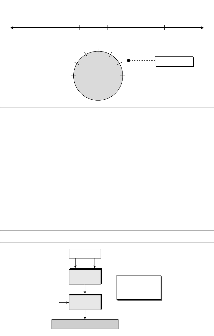
32 CHAPTER 2 MATHEMATICS OF CRYPTOGRAPHY
distribution of integers in Z
n
. Figure 2.12 shows the comparison between the two. Integers
0 to n − 1 are spaced evenly around a circle. All congruent integers modulo n occupy
the same point on the circle. Positive and negative integers from Z are mapped to the
circle in such a way that there is a symmetry between them.
Example 2.15
We use modular arithmetic in our daily life; for example, we use a clock to measure time. Our
clock system uses modulo
12 arithmetic. However, instead of a 0 we use the number 12. So our
clock system starts with 0 (or 12) and goes until 11. Because our days last 24 hours, we navigate
around the circle two times and denote the first revolution as
A.M. and the second as P.M.
Operations in Z
n
The three binary operations (addition, subtraction, and multiplication) that we dis-
cussed for the set Z can also be defined for the set Z
n
. The result may need to be
mapped to Z
n
using the mod operator as shown in Figure 2.13.
Figure 2.12 Comparison of Z and Z
n
using graphs
Figure 2.13 Binary operations in Z
n
0 11 22
(n − 1)−(n − 1)
(n − 1)
(n − 2)
0
1
2
Z
n
Z
a ≡ 2 (mod n)
n
Z
n
= { 0, 1, 2, . . . , (n − 1) }
Z or Z
n
c
a b
mod
+, ×−,
Operations
(a + b) mod n = c
(a − b) mod n = c
(a × b) mod n = c

SECTION 2.2 MODULAR ARITHMETIC 33
Actually, two sets of operators are used here. The first set is one of the binary oper-
ators (+, −, ×); the second is the mod operator. We need to use parentheses to emphasize
the order of operations. As Figure 2.13 shows, the inputs (a and b) can be members of
Z
n
or Z.
Example 2.16
Perform the following operations (the inputs come from Z
n
):
a. Add 7 to 14 in Z
15
.
b. Subtract 11 from 7 in Z
13
.
c. Multiply 11 by 7 in Z
20
.
Solution
The following shows the two steps involved in each case:
Example 2.17
Perform the following operations (the inputs come from either Z or Z
n
):
a. Add 17 to 27 in Z
14
.
b. Subtract 43 from 12 in Z
13
.
c. Multiply 123 by −10 in Z
19
.
Solution
The following shows the two steps involved in each case:
Properties
We mentioned that the two inputs to the three binary operations in the modular arithmetic
can come from Z or Z
n
. The following properties allow us to first map the two inputs to
Z
n
(if they are coming from Z) before applying the three binary operations (+, −, ×).
Interested readers can find proofs for these properties in Appendix Q.
Figure 2.14 shows the process before and after applying the above properties.
Although the figure shows that the process is longer if we apply the above properties,
we should remember that in cryptography we are dealing with very large integers.
For example, if we multiply a very large integer by another very large integer, we
(14
+
7) mod 15
→ (
21) mod 15
=
6
(7
−
11) mod 13
→ (−4)
mod 13
=
9
(7
×
11) mod 20
→ (77)
mod 20
=
17
(17 + 27) mod 14
→ (
44) mod 14 = 2
(12
−
43) mod 13
→ (−31)
mod 13 = 8
(123
×
(
−
10)) mod 19
→ (−1230)
mod 19 = 5
First Property:
(a + b) mod n = [(a mod n) + (b mod n)] mod n
Second Property: (a
−
b) mod n = [(a mod n)
−
(b mod n)] mod n
Third Property:
(a
×
b) mod n = [(a mod n)
×
(b mod n)] mod n

34 CHAPTER 2 MATHEMATICS OF CRYPTOGRAPHY
may have an integer that is too large to be stored in the computer. Applying the
above properties make the first two operands smaller before the multiplication oper-
ation is applied. In other words, the properties allow us to work with smaller num-
bers. This fact will manifest itself more clearly in discussion of the exponential
operation in later chapters.
Example 2.18
The following shows the application of the above properties:
1. (1,723,345 + 2,124,945) mod 11 = (8 + 9) mod 11 = 6
2. (1,723,345 − 2,124,945) mod 16 = (8 − 9) mod 11 = 10
3. (1,723,345 × 2,124,945) mod 16 = (8 × 9) mod 11 = 6
Example 2.19
In arithmetic, we often need to find the remainder of powers of 10 when divided by an integer.
For example, we need to find 10 mod 3, 10
2
mod 3, 10
3
mod 3, and so on. We also need to find 10
mod 7, 10
2
mod 7, 10
3
mod 7, and so. The third property of the mod operator mentioned above
makes life much easier.
We have
Figure 2.14
Properties of mod operator
10
n
mod x = (10 mod x)
n
mod x Applying the third property n times.
10 mod 3 = 1
→
10
n
mod 3 = (10 mod 3)
n
=
1
10 mod 9 = 1 → 10
n
mod 9 = (10 mod 9)
n
= 1
10 mod 7 = 3
→
10
n
mod 7 = (10 mod 7)
n
= 3
n
mod 7
n
a. Original process
n
Z
n
= { 0, 1, 2, . . . , (n − 1)}
Z or Z
n
c
a b
mod
+, ⋅
−,
b. A
pp
l
y
in
g
p
ro
p
erties
n
n
Z
n
= {0, 1, 2, . . . , (n − 1)}
Z or Z
n
a b
mod
+, ⋅
−,
mod
mod
a mod n b mod n
c

SECTION 2.2 MODULAR ARITHMETIC 35
Example 2.20
We have been told in arithmetic that the remainder of an integer divided by 3 is the same as the
remainder of the sum of its decimal digits. In other words, the remainder of dividing 6371 by 3
is the same as dividing 17 by 3 because 6 + 3 + 7 + 1 = 17. We can prove this claim using the
properties of the mod operator. We write an integer as the sum of its digits multiplied by the
powers of 10.
Now we can apply the mod operator to both sides of the equality and use the result of the
previous example that 10
n
mod 3 is 1.
Inverses
When we are working in modular arithmetic, we often need to find the inverse of a
number relative to an operation. We are normally looking for an additive inverse (rela-
tive to an addition operation) or a multiplicative inverse (relative to a multiplication
operation).
Additive Inverse
In Z
n
, two numbers a and b are additive inverses of each other if
In Z
n
, the additive inverse of a can be calculated as b = n − a. For example, the
additive inverse of 4 in Z
10
is 10 − 4 = 6.
Note that in modular arithmetic, each number has an additive inverse and the inverse is
unique; each number has one and only one additive inverse. However, the inverse of the
number may be the number itself.
Example 2.21
Find all additive inverse pairs in Z
10
.
a = a
n
× 10
n
+
. . .
+ a
1
× 10
1
+ a
0
× 10
0
For example: 6371 = 6 × 10
3
+ 3 × 10
2
+ 7 × 10
1
+ 1 × 10
0
a mod 3 = (a
n
× 10
n
+
. . .
+ a
1
× 10
1
+ a
0
× 10
0
) mod 3
= (a
n
× 10
n
) mod 3 +
. . .
+ (a
1
× 10
1
) mod 3
+ (a
0
× 10
0
) mod 3
= (a
n
mod 3) × (10
n
mod 3) +
. . .
+ (a
1
mod 3) × (10
1
mod 3)
+
(a
0
mod 3) × (10
0
mod 3)
= a
n
mod 3 +
. . .
+ a
1
mod 3
+ a
0
mod 3
= (a
n
+
. . .
+ a
1
+ a
0
) mod 3
a + b ≡ 0 (mod n)
In modular arithmetic, each integer has an additive inverse.
The sum of an integer and its additive inverse is congruent to 0 modulo n.

36 CHAPTER 2 MATHEMATICS OF CRYPTOGRAPHY
Solution
The six pairs of additive inverses are (0, 0), (1, 9), (2, 8), (3, 7), (4, 6), and (5, 5). In this list, 0 is
the additive inverse of itself; so is 5. Note that the additive inverses are reciprocal; if 4 is the addi-
tive inverse of 6, then 6 is also the additive inverse of 4.
Multiplicative Inverse
In Z
n
, two numbers a and b are the multiplicative inverse of each other if
For example, if the modulus is 10, then the multiplicative inverse of 3 is 7. In other
words, we have (3 × 7) mod 10 = 1.
It can be proved that a has a multiplicative inverse in Z
n
if and only if gcd (n, a)
= 1.
In this case, a and n are said to be relatively prime.
Example 2.22
Find the multiplicative inverse of 8 in Z
10
.
Solution
There is no multiplicative inverse because gcd (10, 8) = 2 ≠ 1. In other words, we cannot find any
number between 0 and 9 such that when multiplied by 8, the result is congruent to 1.
Example 2.23
Find all multiplicative inverses in Z
10
.
Solution
There are only three pairs: (1, 1), (3, 7) and (9, 9). The numbers 0, 2, 4, 5, 6, and 8 do not have a
multiplicative inverse. We can see that
Example 2.24
Find all multiplicative inverse pairs in Z
11
.
Solution
We have seven pairs: (1, 1), (2, 6), (3, 4), (5, 9), (7, 8), (9, 9), and (10, 10). In moving from Z
10
to
Z
11
, the number of pairs doubles. The reason is that in Z
11
, gcd (11, a) is 1 (relatively prime) for
all values of a except 0. It means all integers 1 to 10 have multiplicative inverses.
The extended Euclidean algorithm we discussed earlier in the chapter can find the
multiplicative inverse of b in Z
n
when n and b are given and the inverse exists. To show
a × b ≡ 1 (mod n)
In modular arithmetic, an integer may or may not have a multiplicative inverse.
When it does, the product of the integer and its multiplicative inverse is congruent
to 1 modulo n.
(1 × 1) mod 10 = 1 (3 × 7) mod 10 = 1 (9 × 9) mod 10 = 1
The integer a in Z
n
has a multiplicative inverse if and only if gcd (n, a) ≡≡
≡≡
1 (mod n)

SECTION 2.2 MODULAR ARITHMETIC 37
this, let us replace the first integer a with n (the modulus). We can say that the algorithm
can find s and t such s × n + b × t = gcd (n, b). However, if the multiplicative inverse of
b exists, gcd (n, b) must be 1. So the relationship is
Now we apply the modulo operator to both sides. In other words, we map each side
to Z
n
. We will have
Note that [(s × n) mod n] in the third line is 0 because if we divide (s × n) by n, the
quotient is s but the remainder is 0.
Figure 2.15 shows how we find the multiplicative inverse of a number using the
extended Euclidean algorithm.
Example 2.25
Find the multiplicative inverse of 11 in Z
26
.
(s ××
××
n) ++
++
(b ××
××
t) ==
==
1
(s
×
n + b
×
t) mod n = 1 mod n
[(s
×
n) mod n]
+
[
(
b
×
t) mod n] = 1 mod n
0
+
[
(
b
×
t) mod n] = 1
(
b
×
t) mod n = 1 → This means t is the multiplicative inverse of b in Z
n
The extended Euclidean algorithm finds the multiplicative inverses of b in Z
n
when n
and b are given and gcd (n, b) ==
==
1.
The multiplicative inverse of b is the value of t after being mapped to Z
n
.
Figure 2.15
Using the extended Euclidean algorithm to find the multiplicative inverse
If r
1
= 1, b
−1
= t
1
b. Algorithm
}
{
while (
r
2
> 0)
if (
r
1
= 1) then
b
−1
←
t
1
q
←
r
1
/
r
2
;
r
1
←
n
;
r
2
←
b
;
t
1
← 0;
t
2
← 1;
r
←
r
1
−
q
×
r
2
;
r
1
←
r
2
;
r
2
←
r
;
t
←
t
1
−
q
×
t
2
;
t
1
←
t
2
;
t
2
←
t
;
a. Process
r
r
gcd (n, b) = r
1
r
2
r
1
r
2
r
1
0
r
1
0
t
1
= 0 t
2
= 1
t
t
t
2
t
1
t
2
t
1
t
t
1
t
2
r
1
= n r
2
= b

38 CHAPTER 2 MATHEMATICS OF CRYPTOGRAPHY
Solution
We use a table similar to the one we used before with r
1
= 26 and r
2
= 11. We are interested only
in the value of t.
The gcd (26, 11) is 1, which means that the multiplicative inverse of 11 exists. The extended
Euclidean algorithm gives t
1
= −7. The multiplicative inverse is (−7) mod 26 = 19. In other words,
11 and 19 are multiplicative inverse in Z
26
. We can see that (11 × 19) mod 26 = 209 mod 26 = 1.
Example 2.26
Find the multiplicative inverse of 23 in Z
100
.
Solution
We use a table similar to the one we used before with r
1
= 100 and r
2
= 23. We are interested only
in the value of t.
The gcd (100, 23) is 1, which means the inverse of 23 exists. The extended Euclidean algorithm
gives t
1
= −13. The inverse is (−13) mod 100 = 87. In other words, 13 and 87 are multiplicative
inverses in Z
100
. We can see that (23 × 87) mod 100 = 2001 mod 100 = 1.
Example 2.27
Find the inverse of 12 in Z
26
.
Solution
We use a table similar to the one we used before, with r
1
= 26 and r
2
= 12.
The gcd (26, 12) = 2 ≠ 1, which means there is no multiplicative inverse for 12 in Z
26
.
q r
1
r
2
r t
1
t
2
t
2 26 11 4 0 1 −2
2 11 4 3 1 −2 5
1 4 3 1 −2 5 −7
3 3 1 0 5 −7 26
1 0 −7 26
q r
1
r
2
r t
1
t
2
t
4 100 23 8 0 1 −4
2 23 8 7 1 −4 19
1 8 7 1 −4 9 −13
7 7 1 0 9 −13 100
1 0 −13 100
q r
1
r
2
r t
1
t
2
t
2 26 12 2 0 1 −2
6 12 2 0 1 −2 13
2 0 −2 13

SECTION 2.2 MODULAR ARITHMETIC 39
Addition and Multiplication Tables
Figure 2.16 shows two tables for addition and multiplication. In the addition table, each
integer has an additive inverse. The inverse pairs can be found when the result of addi-
tion is zero. We have (0, 0), (1, 9), (2, 8), (3, 7), (4, 6), and (5, 5). In the multiplication
table we have only three multiplicative pairs (1, 1), (3, 7) and (9, 9). The pairs can be
found whenever the result of multiplication is 1. Both tables are symmetric with respect
to the diagonal of elements that moves from the top left to the bottom right, revealing
the commutative property for addition and multiplication (a + b = b + a and a × b = b × a).
The addition table also shows that each row or column is a permutation of another row
or column. This is not true for the multiplication table.
Different Sets for Addition and Multiplication
In cryptography we often work with inverses. If the sender uses an integer (as the
encryption key), the receiver uses the inverse of that integer (as the decryption key). If
the operation (encryption/decryption algorithm) is addition, Z
n
can be used as the set of
possible keys because each integer in this set has an additive inverse. On the other hand,
if the operation (encryption/decryption algorithm) is multiplication, Z
n
cannot be the
set of possible keys because only some members of this set have a multiplicative
inverse. We need another set. The new set, which is a subset of Z
n
includes only inte-
gers in Z
n
that have a unique multiplicative inverse. This set is called Z
n
*
. Figure 2.17
shows some instances of two sets. Note that Z
n
*
can be made from multiplication tables,
such as the one shown in Figure 2.16.
Each member of Z
n
has an additive inverse, but only some members have a multi-
plicative inverse. Each member of Z
n
*
has a multiplicative inverse, but only some
members have an additive inverse.
Figure 2.16 Addition and multiplication tables for Z
10
We need to use Z
n
when additive inverses are needed; we need to use Z
n
*
when
multiplicative inverses are needed.
1
0
2
3
4
5
6
10 2 3 4 5 6
Addition Table in Z
10
2 40 3 5 61
2 4 73 5 61
2 43 5 6 7 8
9
4
73 5 6 8
94 7 0
5
6 8
9 17 05 6 8
9 17 0 2
7
7
8
9
0
1
2
3
8
8
9
0
1
2
3
4
9
9
0
1
2
3
4
56 8
7
0 28 1 3 4 5 67 9
8
1 39 2 4 5 6 78 0
9
2 40 3 5 6 7 89 1
Multiplication Table in Z
10
1
0
2
3
4
5
6
10 2 3 4 5 6
0 00 0 0 00
1 3 62 4
5
0
0 42 6 8
0
2
83 20 6 9 5
00 2 44 8 6
0 00 50 5 5
8 06 4 6
7
0
7
4
1
8
5
2
8
0
8
6
4
2
0
8
9
0
9
8
7
6
5
40 2
7
1 07 8 2 9 6 30 4
8
4 08 2 8 6 4 20 6
9
7 59 6 4 3 2 10 8

40 CHAPTER 2 MATHEMATICS OF CRYPTOGRAPHY
Two More Sets
Cryptography often uses two more sets: Z
p
and Z
p
*
. The modulus in these two sets is a
prime number. Prime numbers will be discussed in later chapters; suffice it to say that a
prime number has only two divisors: integer 1 and itself.
The set Z
p
is the same as Z
n
except that n is a prime. Z
p
contains all integers from
0 to p − 1. Each member in Z
p
has an additive inverse; each member except 0 has a
multiplicative inverse.
The set Z
p
*
is the same as Z
n
*
except that n is a prime. Z
p
*
contains all integers
from 1 to p − 1. Each member in Z
p
*
has an additive and a multiplicative inverse. Z
p
*
is
a very good candidate when we need a set that supports both additive and multiplicative
inverse.
The following shows these two sets when p = 13.
2.3 MATRICES
In cryptography we need to handle matrices. Although this topic belongs to a special
branch of algebra called linear algebra, the following brief review of matrices is neces-
sary preparation for the study of cryptography. Readers who are familiar with this topic
can skip part or all of this section. The section begins with some definitions and then
shows how to use matrices in modular arithmetic.
Definitions
A matrix is a rectangular array of l × m elements, in which l is the number of rows and
m is the number of columns. A matrix is normally denoted with a boldface uppercase
letter such as A. The element a
ij
is located in the ith row and jth column. Although
the elements can be a set of numbers, we discuss only matrices with elements in Z.
Figure 2.18 shows a matrix.
If a matrix has only one row (l = 1), it is called a row matrix; if it has only one col-
umn (m = 1), it is called a column matrix. In a square matrix, in which there is the
Figure 2.17 Some Z
n
and Z
n
*
sets
Z
13
= {0, 1, 2, 3, 4, 5, 6, 7, 8, 9, 10, 11, 12}
Z
13
∗ = {1, 2, 3, 4, 5, 6, 7, 8, 9, 10, 11, 12}
Z
6
= {0, 1, 2, 3, 4, 5}
Z
7
= {0, 1, 2, 3, 4, 5, 6}
Z
10
= {0, 1, 2, 3, 4, 5, 6, 7, 8, 9}
Z
6
*
= {1, 5}
Z
7
*
= {1, 2, 3, 4, 5, 6}
Z
10
*
= {1, 3, 7, 9}

SECTION 2.3 MATRICES 41
same number of rows and columns (l = m), the elements a
11
, a
22
, . . . , a
mm
make the
main diagonal. An additive identity matrix, denoted as 0, is a matrix with all rows and
columns set to 0’s. An identity matrix, denoted as I, is a square matrix with 1s on the
main diagonal and 0s elsewhere. Figure 2.19 shows some examples of matrices with
elements from Z.
Operations and Relations
In linear algebra, one relation (equality) and four operations (addition, subtraction,
multiplication, and scalar multiplication) are defined for matrices.
Equality
Two matrices are equal if they have the same number of rows and columns and the corre-
sponding elements are equal. In other words, A = B if we have a
ij
= b
ij
for all i’s and j’s.
Addition and Subtraction
Two matrices can be added if they have the same number of columns and rows. This
addition is shown as C = A + B. In this case, the resulting matrix C has also the same
number of rows and columns as A or B. Each element of C is the sum of the two corre-
sponding elements of A and B: c
ij
= a
ij
+ b
ij
. Subtraction is the same except that each
element of B is subtracted from the corresponding element of A: d
ij
= a
ij
− b
ij
.
Example 2.28
Figure 2.20 shows an example of addition and subtraction.
Figure 2.18 A matrix of size l × m
Figure 2.19 Example of matrices
Matrix A:
m columns
l rows
a
11
a
l1
a
21
a
12
a
l2
a
22
a
1m
a
lm
a
2m
. . .
. . .
. . .
. . .
. . .
. . .
Row matrix
Column
matrix
Square
matrix
I
2 1 5 11
2
4
12
23
12
10
21
8
18
31
14 56
1
0 1
0
0
0
0
0
0
0
0

42 CHAPTER 2 MATHEMATICS OF CRYPTOGRAPHY
Multiplication
We can multiply two matrices of different sizes if the number of columns of the first
matrix is the same as the number of rows of the second matrix. If A is an l × m matrix
and B is an m × p matrix, the product of the two is a matrix C of size l × p. If each ele-
ment of matrix A is called a
ij
, each element of matrix B is called b
jk
, then each element
of matrix C, c
ik
, can be calculated as
Example 2.29
Figure 2.21 shows the product of a row matrix (1 × 3) by a column matrix (3 × 1). The result is a
matrix of size 1 × 1.
Example 2.30
Figure 2.22 shows the product of a 2 × 3 matrix by a 3 × 4 matrix. The result is a 2 × 4 matrix.
Scalar Multiplication
We can also multiply a matrix by a number (called a scalar). If A is an l × m matrix and x
is a scalar, C = xA is a matrix of size l × m, in which c
ij
= x × a
ij
.
Figure 2.20 Addition and subtraction of matrices
c
ik
= ∑ a
ij
× b
jk
= a
i1
× b
1j
+ a
i2
× b
2j
+
. . .
+ a
im
× b
mj
Figure 2.21 Multiplication of a row matrix by a column matrix
Figure 2.22 Multiplication of a 2 × 3 matrix by a 3 × 4 matrix
=
12
11 12 30
4 4
C = A + B
5
3 2 10
2 1
+
7
8 10 20
2 3
=
−2
−5 −8 10
0 −2
D = A − B
5
3 2 10
2 1
−
7
8 10 20
2 3
In which:
=
×
AC B
5 2 1
53
7
8
2
53 = 5 × 7 + 2 × 8 + 1 × 2
=
18
21 22 7
14 952
41
3
0 0 2
2 17
8
3 4 01
C A
B
5
3 2 4
2 1
×

SECTION 2.3 MATRICES 43
Example 2.31
Figure 2.23 shows an example of scalar multiplication.
Determinant
The determinant of a square matrix A of size m × m denoted as det (A) is a scalar cal-
culated recursively as shown below:
Example 2.32
Figure 2.24 shows how we can calculate the determinant of a 2 × 2 matrix based on the determi-
nant of a 1 × 1 matrix using the above recursive definition. The example shows that when m is 1
or 2, it is very easy to find the determinant of a matrix.
Example 2.33
Figure 2.25 shows the calculation of the determinant of a 3
×
3 matrix.
Figure 2.23
Scalar multiplication
1. If m = 1, det (A) = a
11
2. If m > 1, det (A) = (−1)
i+ j
× a
ij
× det (A
ij
)
Where A
ij
is a matrix obtained from A by deleting the ith row and jth column.
The determinant is defined only for a square matrix.
Figure 2.24
Calculating the determinant of a 2
×
2 matrix
Figure 2.25
Calculating the determinant of a 3
×
3 matrix
B
15
9 6 12
6 3
A
5
3 2 4
2 1
= 3 ×
i=1...m
+ (−1)
1+2
× 2 × det
4
= (−1)
1+1
× 5 × det
3
det 5 × 4 − 2 × 3 = 14
5
3 4
2
= a
11
× a
22
− a
12
× a
21
detor
a
11
a
21
a
22
a
12
= (+1) × 5 × (+4) + (−1) × 2 × (24) + (+1) × 1 × (3) = −25
= (−1)
1+1
× 5 × det + (−1)
1+2
× 2 × det + (−1)
1+3
× 1 × det
det
5
3
2
0
1
2
−4
6
1
0
1 6
−4 3
2 6
−4 3
2 1
0

44 CHAPTER 2 MATHEMATICS OF CRYPTOGRAPHY
Inverses
Matrices have both additive and multiplicative inverses.
Additive Inverse
The additive inverse of matrix A is another matrix B such that A + B = 0. In other
words, we have b
ij
= − a
ij
for all values of i and j. Normally the additive inverse of A is
defined by −A.
Multiplicative Inverse
The multiplicative inverse is defined only for square matrices. The multiplicative
inverse of a square matrix A is a square matrix B such that A × B = B
× A =
I. Normally
the multiplicative inverse of A is defined by A
−1
. The multiplicative inverse exists only
if the det(A) has a multiplicative inverse in the corresponding set. Since no integer has
a multiplicative inverse in Z, there is no multiplicative inverse of a matrix in Z. How-
ever, matrices with real elements have inverses only if det (A) ≠ 0.
Residue Matrices
Cryptography uses residue matrices: matrices with all elements are in Z
n
. All opera-
tions on residue matrices are performed the same as for the integer matrices except that
the operations are done in modular arithmetic. One interesting result is that a residue
matrix has a multiplicative inverse if the determinant of the matrix has a multiplicative
inverse in Z
n
.
In other words, a residue matrix has a multiplicative inverse if gcd
(det(A), n) = 1.
Example 2.34
Figure 2.26 shows a residue matrix A in Z
26
and its multiplicative inverse A
−1
. We have det(A) = 21
which has the multiplicative inverse 5 in Z
26
. Note that when we multiply the two matrices, the
result is the multiplicative identity matrix in Z
26
.
Multiplicative inverses are only defined for square matrices.
Figure 2.26 A residue matrix and its multiplicative inverse
A =
det(A) = 21
det(A
−1
) = 5
3
1
6
4
3
7
9
5 7
13 5 4
2
17
2
16
A
−1
=
15
23
15
9
16
0
18
21 0
24 7 15
22
3
15
3

SECTION 2.4 LINEAR CONGRUENCE 45
Congruence
Two matrices are congruent modulo n, written as A ≡ B (mod n), if they have the same
number of rows and columns and all corresponding elements are congruent modulo n.
In other words, A ≡ B (mod n) if a
ij
≡ b
ij
(mod n) for all i’s and j’s.
2.4 LINEAR CONGRUENCE
Cryptography often involves solving an equation or a set of equations of one or more
variables with coefficient in Z
n
. This section shows how to solve equations when the
power of each variable is 1 (linear equation).
Single-Variable Linear Equations
Let us see how we can solve equations involving a single variablethat is, equations of
the form ax ≡ b (mod n). An equation of this type might have no solution or a limited
number of solutions. Assume that the gcd (a, n) = d. If d b, there is no solution. If d
|
b,
there are d solutions.
If d
|
b, we use the following strategy to find the solutions:
1. Reduce the equation by dividing both sides of the equation (including the modu-
lus) by d.
2. Multiply both sides of the reduced equation by the multiplicative inverse of a to
find the particular solution x
0
.
3. The general solutions are x = x
0
+ k (n
/
d) for k = 0, 1, . . . , (d − 1).
Example 2.35
Solve the equation 10x ≡ 2 (mod 15).
Solution
First we find the gcd (10 and 15) = 5. Since 5 does not divide 2, we have no solution.
Example 2.36
Solve the equation 14x ≡ 12 (mod 18).
Solution
Note that gcd (14 and 18) = 2. Since 2 divides 12, we have exactly two solutions, but first we
reduce the equation.
Both solutions, 6 and 15 satisfy the congruence relation, because (14
×
6) mod 18 = 12 and also
(14
×
15) mod 18 = 12.
14x
≡
12 (mod 18)
→
7x
≡
6 (mod 9)
→
x
≡
6
(7
−1
)
(mod 9)
x
0
=
(6
×
7
−1
) mod 9
=
(6
×
4) (mod 9)
=
6
x
1
=
x
0
+ 1
×
(18/2)
=
15

46 CHAPTER 2 MATHEMATICS OF CRYPTOGRAPHY
Example 2.37
Solve the equation 3x + 4 ≡ 6 (mod 13).
Solution
First we change the equation to the form ax ≡ b (mod n). We add −4 (the additive inverse of 4) to
both sides, which give 3x
≡ 2 (mod 13). Because gcd (3, 13) = 1, the equation has only one solu-
tion, which is x
0
= (2 × 3
−
1
) mod 13 = 18 mod 13 = 5. We can see that the answer satisfies the
original equation: 3
× 5 + 4 ≡ 6 (mod 13).
Set of Linear Equations
We can also solve a set of linear equations with the same modulus if the matrix
formed from the coefficients of the variables is invertible. We make three matrices.
The first is the square matrix made from the coefficients of variables. The second is a
column matrix made from the variables. The third is a column matrix made from the
values at the right-hand side of the congruence operator. We can interpret the set of
equations as matrix multiplication. If both sides of congruence are multiplied by the
multiplicative inverse of the first matrix, the result is the variable matrix at the right-
hand side, which means the problem can be solved by a matrix multiplication as
shown in Figure 2.27.
Example 2.38
Solve the set of following three equations:
Figure 2.27 Set of linear equations
3x + 5y + 7z ≡ 3 (mod 16)
x +
4y + 13z ≡ 5 (mod 16)
2x + 7y + 3z
≡ 4 (mod 16)
a. Equations
+
+
+
+
+
+
+
+
+
≡
≡
≡
a
12
x
2
a
22
x
2
a
n2
x
2
a
1n
x
n
a
2n
x
n
a
nn
x
n
a
11
x
1
a
21
x
1
a
n1
x
1
b
n
b
2
b
1
. . .
. . .
. . .
. . .
. . .
. . .
. . .
c. Solution b. Inter
p
retation
a
11
a
21
a
n1
a
1n
a
2n
a
nn
a
12
a
22
a
n2
. . .
. . .
. . .
. . .
. . .
x
1
≡
x
2
x
n
. . .
b
1
b
2
b
n
. . .
. . .
−1
a
11
a
21
a
n1
a
1n
a
2n
a
nn
a
12
a
22
a
n2
. . .
. . .
. . .
. . .
. . .
x
1
≡
x
2
x
n
. . .
b
1
b
2
b
n
. . .
. . .

SECTION 2.6 KEY TERMS 47
Solution
Here x, y, and z play the roles of x
1
, x
2
, and x
3
. The matrix formed by the set of equations is
invertible. We find the multiplicative inverse of the matrix and multiply it by the column matrix
formed from 3, 5, and 4. The result is x
≡
15 (mod 16), y
≡
4 (mod 16), and z
≡
14 (mod 16). We
can check the answer by inserting these values into the equations.
2.5 RECOMMENDED READING
For more details about subjects discussed in this chapter, we recommend the following
books and sites. The items enclosed in brackets refer to the reference list at the end of
the book.
Books
Several books give an easy but thorough coverage of number theory including [Ros06],
[Sch99], [Cou99], and [BW00]. Matrices are discussed in any book about linear alge-
bra; [LEF04], [DF04], and [Dur05] are good texts to start with.
WebSites
The following websites give more information about topics discussed in this chapter.
2.6 KEY TERMS
http://en.wikipedia.org/wiki/Euclidean_algorithm
http://en.wikipedia.org/wiki/Multiplicative_inverse
http://en.wikipedia.org/wiki/Additive_inverse
additive inverse main diagonal
binary operation matrix
column matrix modular arithmetic
congruence modulo operator (mod)
congruence operator modulus
determinant multiplicative inverse
divisibility relatively prime
Euclidean algorithm residue
extended Euclidean algorithm residue class
greatest common divisor row matrix
identity matrix scalar
integer arithmetic
set of integers, Z
least residue set of residues, Z
n
linear congruence square matrix
linear Diophantine equation

48 CHAPTER 2 MATHEMATICS OF CRYPTOGRAPHY
2.7 SUMMARY
❏ The set of integers, denoted by Z, contains all integral numbers from negative
infinity to positive infinity. Three common binary operations defined for integers
are addition, subtraction, and multiplication. Division does not fit in this category
because it produces two outputs instead of one.
❏ In integer arithmetic, if we divide a by n, we can get q and r. The relationship
between these four integers can be shown as a = q × n + r. We say a|b if a = q × n.
We mentioned four properties of divisibility in this chapter.
❏ Two positive integers can have more than one common divisor. But we are nor-
mally interested in the greatest common divisor. The Euclidean algorithm gives an
efficient and systematic way to calculation of the greatest common divisor of two
integer.
❏ The extended Euclidean algorithm can calculate gcd (a, b) and at the same time
calculate the value of s and t to satisfy the equation as + bt = gcd (a, b).
❏ A linear Diophantine equation of two variables is ax + by = c. It has a particular
and general solution.
❏ In modular arithmetic, we are interested only in remainders; we want to know the
value of r when we divide a by n. We use a new operator called modulo operator
(mod) so that a mod n = r. Now n is called the modulus; r is called the residue.
❏ The result of the modulo operation with modulus n is always an integer between 0
and. We can say that the modulo operation creates a set, which in modular arith-
metic is referred to as the set of least residues modulo n, or Z
n
.
❏ Mapping from Z to Z
n
is not one-to-one. Infinite members of Z can map to one
member of Z
n
. In modular arithmetic, all integers in Z that map to one integer in
Z
n
are called congruent modulo n. To show that two integers are congruent, we use
the congruence operator (≡).
❏ A residue class [a] is the set of integers congruent modulo n. It is the set of all inte-
gers such that x = a (mod n).
❏ The three binary operations (addition, subtraction, and multiplication) defined for
the set Z can also be defined for the set Z
n
. The result may need to be mapped to
Z
n
using the mod operator.
❏ Several properties were defined for the modulo operation in this chapter.
❏ In Z
n
, two numbers a and b are additive inverses of each other if a + b ≡ 0 (mod n).
They are the multiplicative inverse of each other if a × b ≡ 1 (mod n). The integer a
has a multiplicative inverse in Z
n
if and only if gcd (n, a) = 1 (a and n are relatively
prime).
❏ The extended Euclidean algorithm finds the multiplicative inverses of b in Z
n
when
n and b are given and gcd (n, b) = 1. The multiplicative inverse of b is the value of
t after being mapped to Z
n
.
❏ A matrix is a rectangular array of l × m elements, in which l is the number of rows
and m is the number of columns. We show a matrix with a boldface uppercase let-
ter such as A. The element a
ij
is located in the ith row and jth column.

SECTION 2.8 PRACTICE SET 49
❏
Two matrices are equal if they have the same number of rows and columns and the
corresponding elements are equal.
❏ Addition and subtraction are done only on matrices of equal sizes. We can multiply
two matrices of different sizes if the number of columns of the first matrix is the
same as the number of rows of the second matrix.
❏ In residue matrices, all elements are in Z
n
. All operations on residue matrices are
done in modular arithmetic. A residue matrix has an inverse if the determinant of
the matrix has an inverse.
❏ An equation of the form ax ≡ b (mod n) may have no solution or a limited number
of solutions. If gcd (a, n)|b, there is a limited number of solutions.
❏ A set of linear equations with the same modulus can be solved if the matrix formed
from the coefficients of variables has an inverse.
2.8 PRACTICE SET
Review Questions
1. Distinguish between Z and Z
n
. Which set can have negative integers? How can we
map an integer in Z to an integer in Z
n
?
2. List four properties of divisibility discussed in this chapter. Give an integer with
only one divisor. Give an integer with only two divisors. Give an integer with more
than two divisors.
3. Define the greatest common divisor of two integers. Which algorithm can effec-
tively find the greatest common divisor?
4. What is a linear Diophantine equation of two variables? How many solutions can
such an equation have? How can the solution(s) be found?
5. What is the modulo operator, and what is its application? List all properties we
mentioned in this chapter for the modulo operation.
6. Define congruence and compare with equality.
7. Define a residue class and a least residue.
8. What is the difference between the set Z
n
and the set
Z
n
*
?
In which set does each ele-
ment have an additive inverse? In which set does each element have a multiplicative
inverse? Which algorithm is used to find the multiplicative inverse of an integer in Z
n
?
9. Define a matrix. What is a row matrix? What is a column matrix? What is a square
matrix? What type of matrix has a determinant? What type of matrix can have an
inverse?
10. Define linear congruence. What algorithm can be used to solve an equation of type
ax ≡ b (mod n)? How can we solve a set of linear equations?
Exercises
11. Which of the following relations are true and which are false?
5|26 3|123 27 127 15 21 23|96 8|5
50 CHAPTER 2 MATHEMATICS OF CRYPTOGRAPHY
12. Using the Euclidean algorithm, find the greatest common divisor of the following
pairs of integers.
a. 88 and 220
b. 300 and 42
c. 24 and 320
d. 401 and 700
13. Solve the following.
a. Given gcd (a, b) = 24, find gcd (a, b, 16).
b. Given gcd (a, b, c) = 12, find gcd (a, b, c, 16)
c. Find gcd (200, 180, and 450).
d. Find gcd (200, 180, 450, 610).
14. Assume that n is a nonnegative integer.
a. Find gcd (2n + 1, n).
b. Using the result of part a, find gcd (201, 100), gcd (81, 40), and gcd (501,
250).
15. Assume that n is a nonnegative integer.
a. Find gcd (3n + 1, 2n + 1).
b. Using the result of part a, find gcd (301, 201) and gcd (121, 81).
16. Using the extended Euclidean algorithm, find the greatest common divisor of the
following pairs and the value of s and t.
a. 4 and 7
b. 291 and 42
c. 84 and 320
d. 400 and 60
17. Find the results of the following operations.
a. 22 mod 7
b. 140 mod 10
c. −78 mod 13
d. 0 mod 15
18. Perform the following operations using reduction first.
a. (273 + 147) mod 10
b. (4223 + 17323) mod 10
c. (148 + 14432) mod 12
d. (2467 + 461) mod 12
19. Perform the following operations using reduction first.
a. (125 × 45) mod 10
b. (424 × 32) mod 10
c. (144 × 34) mod 12
d. (221 × 23) mod 22
SECTION 2.8 PRACTICE SET 51
20. Use the properties of the mod operator to prove the following:
a. The remainder of any integer when divided by 10 is the rightmost digit.
b. The remainder of any integer when divided by 100 is the integer made of the
two rightmost digits.
c. The remainder of any integer when divided by 1000 is the integer made of the
three rightmost digits.
21. We have been told in arithmetic that the remainder of an integer divided by 5 is the
same as the remainder of division of the rightmost digit by 5. Use the properties of
the mod operator to prove this claim.
22. We have been told in arithmetic that the remainder of an integer divided by 2 is the
same as the remainder of division of the rightmost digit by 2. Use the properties of
the mod operator to prove this claim.
23. We have been told in arithmetic that the remainder of an integer divided by 4 is the
same as the remainder of
division of the two rightmost digits by 4. Use the proper-
ties of the mod operator to prove this claim.
24. We have been told in arithmetic that the remainder of an integer divided by 8 is the
same as the remainder of division of the rightmost three digits by 8. Use the proper-
ties of the mod operator to prove this claim.
25. We have been told in arithmetic that the remainder of an integer divided by 9 is the
same as the remainder of division of the sum of its decimal digits by 9. In other
words, the remainder of dividing 6371 by 9 is the same as dividing 17 by 9 because
6 + 3 + 7 + 1 = 17. Use the properties of the mod operator to prove this claim.
26. The following shows the remainders of powers of 10 when divided by 7. We can
prove that the pattern will be repeated for higher powers.
Using the above information, find the remainder of an integer when divided by 7.
Test your method with 631453672.
27. The following shows the remainders of powers of 10 when divided by 11. We can
prove that the pattern will be repeated for higher powers.
Using the above information, find the remainder of an integer when divided by 11.
Test your method with 631453672.
28. The following shows the remainders of powers of 10 when divided by 13. We can
prove that the pattern will be repeated for higher powers.
Using the above information, find the remainder of an integer when divided by 13.
Test your method with 631453672.
10
0
mod 7 = 1 10
1
mod 7 = 3 10
2
mod 7 = 2
10
3
mod 7 = −1 10
4
mod 7 = −3 10
5
mod 7 = −2
10
0
mod 11 = 1 10
1
mod 11 = −1 10
2
mod 11 = 1 10
3
mod 11 = −1
10
0
mod 13 = 1 10
1
mod 13 = −3 10
2
mod 13 = −4
10
3
mod 13 = −1 10
4
mod 13 = 3 10
5
mod 13 = 4
52 CHAPTER 2 MATHEMATICS OF CRYPTOGRAPHY
29. Let us assign numeric values to the uppercase alphabet (A = 0, B = 1, . . . Z = 25).
We can now do modular arithmetic on the system using modulo 26.
a. What is (A + N) mod 26 in this system?
b. What is (A + 6) mod 26 in this system?
c. What is (Y − 5) mod 26 in this system?
d. What is (C −10) mod 26 in this system?
30. List all additive inverse pairs in modulus 20.
31. List all multiplicative inverse pairs in modulus 20.
32. Find the multiplicative inverse of each of the following integers in Z
180
using the
extended Euclidean algorithm.
a. 38
b. 7
c. 132
d. 24
33. Find the particular and the general solutions to the following linear Diophantine
equations.
a. 25x + 10y = 15
b. 19x + 13y = 20
c. 14x + 21y = 77
d. 40x + 16y = 88
34. Show that there are no solutions to the following linear Diophantine equations:
a. 15x + 12y = 13
b. 18x + 30y = 20
c. 15x + 25y = 69
d. 40x + 30y = 98
35. A post office sells only 39-cent and 15-cent stamps. Find the number of stamps a
customer needs to buy to put $2.70 postage on a package. Find a few solutions.
36. Find all solutions to each of the following linear equations:
a. 3x ≡ 4 (mod 5)
b. 4x ≡ 4 (mod 6)
c. 9x ≡ 12 (mod 7)
d. 256x ≡ 442 (mod 60)
37. Find all solutions to each of the following linear equations:
a. 3x + 5 ≡ 4 (mod 5)
b. 4x + 6 ≡ 4 (mod 6)
c. 9x + 4 ≡ 12 (mod 7)
d. 232x + 42 ≡ 248 (mod 50)
38. Find (A × B) mod 16 using the matrices in Figure 2.28.

SECTION 2.8 PRACTICE SET 53
39. In Figure 2.29, find the determinant and the multiplicative inverse of each residue
matrix over Z
10
.
40. Find all solutions to the following sets of linear equations:
a. 3x + 5y ≡ 4 (mod 5)
2x + y ≡ 3 (mod 5)
b. 3x + 2y ≡ 5 (mod 7)
4x + 6y ≡ 4 (mod 7)
c. 7x + 3y ≡ 3 (mod 7)
4x + 2y ≡ 5 (mod 7)
d. 2x + 3y ≡ 5 (mod 8)
x + 6y ≡ 3 (mod 8)
Figure 2.28 Matrices for Exercise 38
Figure 2.29 Matrices for Exercise 39
×
A
B
2
4
12
A
4
1
8
8
3
6
3
1
5
B
0
1
2
0
4
1
2
1
5
3 7 10
×
C
A
3
1
5
1
8
8
3
4 6
3
1 1
0
B
4
1 1
2

55
CHAPTER 3
Traditional Symmetric-Key Ciphers
Objectives
This chapter presents a survey of traditional symmetric-key ciphers used
in the past. By explaining the principles of such ciphers, it prepares the
reader for the next few chapters, which discuss modern symmetric-key
ciphers. This chapter has several objectives:
❏ To define the terms and the concepts of symmetric-key ciphers
❏ To emphasize the two categories of traditional ciphers: substitution
ciphers and transposition ciphers
❏ To describe the categories of cryptanalysis used to break the symmetric
ciphers
❏ To introduce the concepts of the stream ciphers and block ciphers
❏ To discuss some very dominant ciphers used in the past, such as the
Enigma machine
The general idea behind symmetric-key ciphers will be introduced here
using examples from cryptography. The terms and definitions presented
are used in all later chapters on symmetric-key ciphers. We then discuss
traditional symmetric-key ciphers. These ciphers are not used today, but
we study them for several reasons. First, they are simpler than modern
ciphers and easier to understand. Second, they show the basic foundation
of cryptography and encipherment: This foundation can be used to better
understand modern ciphers. Third, they provide the rationale for using
modern ciphers, because the traditional ciphers can be easily attacked
using a computer. Ciphers that were secure in earlier eras are no longer
secure in this computer age.

56 CHAPTER 3 TRADITIONAL SYMMETRIC-KEY CIPHERS
3.1 INTRODUCTION
Figure 3.1 shows the general idea behind a symmetric-key cipher.
In Figure 3.1, an entity, Alice, can send a message to another entity, Bob, over an
insecure channel with the assumption that an adversary, Eve, cannot understand the
contents of the message by simply eavesdropping over the channel.
The original message from Alice to Bob is called plaintext; the message that is
sent through the channel is called the ciphertext. To create the ciphertext from the
plaintext, Alice uses an encryption algorithm and a shared secret key. To create the
plaintext from ciphertext, Bob uses a decryption algorithm and the same secret key.
We refer to encryption and decryption algorithms as ciphers. A key is a set of values
(numbers) that the cipher, as an algorithm, operates on.
Note that the symmetric-key encipherment uses a single key (the key itself may be a
set of values) for both encryption and decryption. In addition, the encryption and decryp-
tion algorithms are inverses of each other. If P is the plaintext, C is the ciphertext, and K is
the key, the encryption algorithm E
k
(x) creates the ciphertext from the plaintext; the
decryption algorithm D
k
(x) creates the plaintext from the ciphertext. We assume that
E
k
(x) and D
k
(x) are inverses of each other: they cancel the effect of each other if they are
applied one after the other on the same input. We have
We can prove that the plaintext created by Bob is the same as the one originated by
Alice. We assume that Bob creates P
1
; we prove that P
1
= P:
We need to emphasize that, according to Kerckhoff’s principle (described later), it
is better to make the encryption and decryption public but keep the shared key secret.
Figure 3.1
General idea of symmetric-key cipher
Encryption: C = E
k
(P) Decryption: P = D
k
(C)
In which, D
k
(E
k
(x)) = E
k
(D
k
(x)) = x
Alice: C = E
k
(P) Bob: P
1
= D
k
(C) = D
k
(E
k
(P)) = P
Alice
Plaintext
Ciphertext
Shared
secret key
Encryption
algorithm
................
................
................
................
................
................
................
................
................
................
Bob
Plaintext
Ciphertext
Insecure channel
Secure key-exchange channel
Shared
secret key
Decryption
algorithm
................
................
................
................
................
................
................
................
................
................

SECTION 3.1 INTRODUCTION 57
This means that Alice and Bob need another channel, a secured one, to exchange the
secret key. Alice and Bob can meet once and exchange the key personally. The secured
channel here is the face-to-face exchange of the key. They can also trust a third party to
give them the same key. They can create a temporary secret key using another kind of
cipherasymmetric-key cipherswhich will be described in later chapters. The con-
cern will be dealt with in future chapters. In this chapter, we assume that there is an
established secret key between Alice and Bob.
Using symmetric-key encipherment, Alice and Bob can use the same key for com-
munication on the other direction, from Bob to Alice. This is why the method is called
symmetric.
Another element in symmetric-key encipherment is the number of keys. Alice
needs another secret key to communicate with another person, say David. If there are m
people in a group who need to communicate with each other, how many keys are
needed? The answer is (m
×
(m − 1))/2 because each person needs m − 1 keys to com-
municate with the rest of the group, but the key between A and B can be used in both
directions. We will see in later chapters how this problem is being handled.
Encryption can be thought of as locking the message in a box; decryption can be
thought of as unlocking the box. In symmetric-key encipherment, the same key locks
and unlocks as shown in Figure 3.2. Later chapters show that the asymmetric-key enci-
pherment needs two keys, one for locking and one for unlocking.
Kerckhoff’s Principle
Although it may appear that a cipher would be more secure if we hide both the
encryption/decryption algorithm and the secret key, this is not recommended. Based
on Kerckhoff’s principle, one should always assume that the adversary, Eve, knows
the encryption/decryption algorithm. The resistance of the cipher to attack must be
based only on the secrecy of the key. In other words, guessing the key should be so
difficult that there is no need to hide the encryption/decryption algorithm. This prin-
ciple manifests itself more clearly when we study modern ciphers. There are only a
few algorithms for modern ciphers today. The key domain for each algorithm, how-
ever, is so large that it makes it difficult for the adversary to find the key.
Cryptanalysis
As cryptography is the science and art of creating secret codes, cryptanalysis is the sci-
ence and art of breaking those codes. In addition to studying cryptography techniques,
Figure 3.2
Symmetric-key encipherment as locking and unlocking with the same key
Encryption
algorithm
Decryption
algorithm

58 CHAPTER 3 TRADITIONAL SYMMETRIC-KEY CIPHERS
we also need to study cryptanalysis techniques. This is needed, not to break other peo-
ple’s codes, but to learn how vulnerable our cryptosystem is. The study of cryptanalysis
helps us create better secret codes. There are four common types of cryptanalysis
attacks, as shown in Figure 3.3. We will study some of these attacks on particular ciphers
in this and future chapters.
Ciphertext-Only Attack
In a ciphertext-only attack, Eve has access to only some ciphertext. She tries to find
the corresponding key and the plaintext. The assumption is that Eve knows the algo-
rithm and can intercept the ciphertext. The ciphertext-only attack is the most probable
one because Eve needs only the ciphertext for this attack. To thwart the decryption of a
message by an adversary, a cipher must be very resisting to this type of attack. Figure 3.4
shows the process.
Various methods can be used in ciphertext-only attack. We mention some common
ones here.
Brute-Force Attack
In the brute-force method or exhaustive-key-search method, Eve tries to use all possi-
ble keys. We assume that Eve knows the algorithm and knows the key domain (the list of
Figure 3.3
Cryptanalysis attacks
Figure 3.4
Ciphertext-only attack
Cryptanalysis
attacks
Chosen-ciphertextChosen-plaintextKnown-plaintextCiphertext-only
Eve
Alice
................
................
................
................
................
Bob
Ciphertext
Ciphertext
................
................
................
................
................
Plaintext
Ciphertext
................
................
................
................
................
................
................
................
................
................
Analyze

SECTION 3.1 INTRODUCTION 59
all possible keys). Using the intercepted cipher, Eve decrypts the ciphertext with every
possible key until the plaintext makes sense. Using brute-force attack was a difficult task
in the past; it is easier today using a computer. To prevent this type of attack, the num-
ber of possible keys must be very large.
Statistical Attack
The cryptanalyst can benefit from some inherent characteristics of the plaintext lan-
guage to launch a statistical attack. For example, we know that the letter E is the most-
frequently used letter in English text. The cryptanalyst finds the mostly-used character
in the ciphertext and assumes that the corresponding plaintext character is E. After find-
ing a few pairs, the analyst can find the key and use it to decrypt the message. To pre-
vent this type of attack, the cipher should hide the characteristics of the language.
Pattern Attack
Some ciphers may hide the characteristics of the language, but may create some pat-
terns in the ciphertext. A cryptanalyst may use a pattern attack to break the cipher.
Therefore, it is important to use ciphers that make the ciphertext look as random as
possible.
Known-Plaintext Attack
In a known-plaintext attack, Eve has access to some plaintext/ciphertext pairs
in addition to the intercepted ciphertext that she wants to break, as shown in Figure 3.5.
The plaintext/ciphertext pairs have been collected earlier. For example, Alice has
sent a secret message to Bob, but she has later made the contents of the message public.
Eve has kept both the ciphertext and the plaintext to use them to break the next secret
message from Alice to Bob, assuming that Alice has not changed her key. Eve uses the
relationship between the previous pair to analyze the current ciphertext. The same
methods used in a ciphertext-only attack can be applied here. This attack is easier to
implement because Eve has more information to use for analysis. However, it is less
likely to happen because Alice may have changed her key or may have not disclosed
the contents of any previous messages.
Figure 3.5
Known-plaintext attack
Eve
Alice
................
................
................
................
................
Bob
Ciphertext
Ciphertext
................
................
................
................
................
Plaintext
Ciphertext
................
................
................
................
................
................
................
................
................
................
Analyze
Previous pair
................
................
................
................
................
................
................
................
................
................

60 CHAPTER 3 TRADITIONAL SYMMETRIC-KEY CIPHERS
Chosen-Plaintext Attack
The chosen-plaintext attack is similar to the known-plaintext attack, but the plaintext/
ciphertext pairs have been chosen by the attacker herself. Figure 3.6 shows the process.
This can happen, for example, if Eve has access to Alice’s computer. She can
choose some plaintext and intercept the created ciphertext. Of course, she does not have
the key because the key is normally embedded in the software used by the sender. This
type of attack is much easier to implement, but it is much less likely to happen.
Chosen-Ciphertext Attack
The chosen-ciphertext attack is similar to the chosen-plaintext attack, except that Eve
chooses some ciphertext and decrypts it to form a ciphertext/plaintext pair. This can
happen if Eve has access to Bob’s computer. Figure 3.7 shows the process.
Categories of Traditional Ciphers
We can divide traditional symmetric-key ciphers into two broad categories: substitution
ciphers and transposition ciphers. In a substitution cipher, we replace one symbol in the
Figure 3.6 Chosen-plaintext attack
Figure 3.7
Chosen-ciphertext attack
Eve
Alice
................
................
................
................
................
Bob
Ciphertext
Ciphertext
................
................
................
................
................
Plaintext
Ciphertext
................
................
................
................
................
................
................
................
................
................
Analyze
Eve
Pair created from
chosen plaintext
................
................
................
................
................
................
................
................
................
................
Eve
Alice
................
................
................
................
................
Bob
Ciphertext
Ciphertext
................
................
................
................
................
Plaintext
Ciphertext
................
................
................
................
................
................
................
................
................
................
Analyze
Eve
Pair created from
chosen ciphertext
................
................
................
................
................
................
................
................
................
................

SECTION 3.2 SUBSTITUTION CIPHERS 61
ciphertext with another symbol; in a transposition cipher, we reorder the position of
symbols in the plaintext.
3.2 SUBSTITUTION CIPHERS
A substitution cipher replaces one symbol with another. If the symbols in the plaintext
are alphabetic characters, we replace one character with another. For example, we can
replace letter A with letter D, and letter T with letter Z. If the symbols are digits (0 to 9),
we can replace 3 with 7, and 2 with 6. Substitution ciphers can be categorized as either
monoalphabetic ciphers or polyalphabetic ciphers.
Monoalphabetic Ciphers
We first discuss a group of substitution ciphers called the monoalphabetic ciphers. In
monoalphabetic substitution, a character (or a symbol) in the plaintext is always
changed to the same character (or symbol) in the ciphertext regardless of its position in
the text. For example, if the algorithm says that letter A in the plaintext is changed to
letter D, every letter A is changed to letter D. In other words, the relationship between
letters in the plaintext and the ciphertext is one-to-one.
Example 3.1
The following shows a plaintext and its corresponding ciphertext. We use lowercase characters to
show the plaintext; we use uppercase characters to show the ciphertext. The cipher is probably
monoalphabetic because both l’s (els) are encrypted as O’s.
Example 3.2
The following shows a plaintext and its corresponding ciphertext. The cipher is not monoalpha-
betic because each l (el) is encrypted by a different character. The first l (el) is encrypted as N; the
second as Z.
A substitution cipher replaces one symbol with another.
In monoalphabetic substitution, the relationship between a symbol in the plaintext to a
symbol in the ciphertext is always one-to-one.
Plaintext: hello Ciphertext: KHOOR
Plaintext: hello Ciphertext: ABNZF

62 CHAPTER 3 TRADITIONAL SYMMETRIC-KEY CIPHERS
Additive Cipher
The simplest monoalphabetic cipher is the additive cipher. This cipher is sometimes
called a shift cipher and sometimes a Caesar cipher, but the term additive cipher better
reveals its mathematical nature. Assume that the plaintext consists of lowercase letters
(a to z), and that the ciphertext consists of uppercase letters (A to Z). To be able to
apply mathematical operations on the plaintext and ciphertext, we assign numerical
values to each letter (lower- or uppercase), as shown in Figure 3.8.
In Figure 3.8 each character (lowercase or uppercase) is assigned an integer in Z
26
.
The secret key between Alice and Bob is also an integer in Z
26
. The encryption algorithm
adds the key to the plaintext character; the decryption algorithm subtracts the key from
the ciphertext character. All operations are done in Z
26
. Figure 3.9. shows the process.
We can easily prove that the encryption and decryption are inverse of each other
because plaintext created by Bob (P
1
) is the same as the one sent by Alice (P).
P
1
= (C
−
k) mod 26 = (P + k
−
k) mode 26 = P
Example 3.3
Use the additive cipher with key = 15 to encrypt the message “hello”.
Solution
We apply the encryption algorithm to the plaintext, character by character:
Figure 3.8
Representation of plaintext and ciphertext characters in Z
26
Figure 3.9 Additive cipher
When the cipher is additive, the plaintext, ciphertext, and key are integers in Z
26
.
Plaintext
Value
01 05 06 07 09 10 11 12 13 14 15 16 1708 18 19 2000 21 22 23 24 25
A B C D E F G H J K L M N O P Q RI S T U V W X Y Z
a b c d e f g h j k l m n o p q ri s t u v w x y z
Ciphertext
02 0403
P
C
C
Alice
Bob
Plaintext
Ciphertext
Plaintext
k
Encryption Decryption
C = (P + k) mod 26
k
P
P = (C − k) mod 26

SECTION 3.2 SUBSTITUTION CIPHERS 63
The result is “WTAAD”. Note that the cipher is monoalphabetic because two instances of the
same plaintext character (l’s) are encrypted as the same character (A).
Example 3.4
Use the additive cipher with key = 15 to decrypt the message “WTAAD”.
Solution
We apply the decryption algorithm to the plaintext character by character:
The result is “hello”. Note that the operation is in modulo 26 (see Chapter 2), which means that a
negative result needs to be mapped to Z
26
(for example −15 becomes 11).
Shift Cipher
Historically, additive ciphers are called shift ciphers. The reason is that the encryption algo-
rithm can be interpreted as “shift key characters down” and the encryption algorithm can be
interpreted as “shift key character up”. For example, if the key = 15, the encryption algo-
rithm shifts 15 characters down (toward the end of the alphabet). The decryption algorithm
shifts 15 characters up (toward the beginning of the alphabet). Of course, when we reach
the end or the beginning of the alphabet, we wrap around (manifestation of modulo 26).
Caesar Cipher
Julius Caesar used an additive cipher to communicate with his officers. For this reason,
additive ciphers are sometimes referred to as the Caesar cipher. Caesar used a key of 3
for his communications.
Cryptanalysis
Additive ciphers are vulnerable to ciphertext-only attacks using exhaustive key
searches (brute-force attacks). The key domain of the additive cipher is very small;
there are only 26 keys. However, one of the keys, zero, is useless (the ciphertext is the
same as the plaintext). This leaves only 25 possible keys. Eve can easily launch a brute-
force attack on the ciphertext.
Plaintext: h → 07 Encryption: (07 + 15) mod 26 Ciphertext: 22 → W
Plaintext: e
→ 04 Encryption: (04 + 15) mod 26 Ciphertext: 19 → T
Plaintext: l → 11 Encryption: (11 + 15) mod 26 Ciphertext: 00 → A
Plaintext: l → 11 Encryption: (11 + 15) mod 26 Ciphertext: 00 → A
Plaintext: o → 14 Encryption: (14 + 15) mod 26 Ciphertext: 03 → D
Ciphertext: W → 22 Decryption: (22 − 15) mod 26 Plaintext: 07 → h
Ciphertext: T
→ 19 Decryption: (19 − 15) mod 26 Plaintext: 04 → e
Ciphertext: A → 00 Decryption: (00 − 15) mod 26 Plaintext: 11 → l
Ciphertext: A → 00 Decryption: (00 − 15) mod 26 Plaintext: 11 → l
Ciphertext: D
→ 03 Decryption: (03 − 15) mod 26 Plaintext: 14 → o
Additive ciphers are sometimes referred to as shift ciphers or Caesar cipher.

64 CHAPTER 3 TRADITIONAL SYMMETRIC-KEY CIPHERS
Example 3.5
Eve has intercepted the ciphertext “UVACLYFZLJBYL”. Show how she can use a brute-force
attack to break the cipher.
Solution
Eve tries keys from 1 to 7. With a key of 7, the plaintext is “not very secure”, which makes sense.
Additive ciphers are also subject to statistical attacks. This is especially true if the
adversary has a long ciphertext. The adversary can use the frequency of occurrence of
characters for a particular language. Table 3.1 shows the frequency for an English text
of 100 characters.
However, sometimes it is difficult to analyze a ciphertext based only on information
about the frequency of a single letter; we may need to know the occurrence of specific
letter combinations. We need to know the frequency of two-letter or three-letter strings
in the ciphertext and compare them with the frequency of two-letter or three-letter
strings in the underlying language of the plaintext.
The most common two-letter groups (digrams) and three-letter groups (trigrams)
for the English text are shown in Table 3.2.
Ciphertext: UVACLYFZLJBYL
K = 1 → Plaintext: tuzbkxeykiaxk
K = 2 → Plaintext: styajwdxjhzwj
K = 3 → Plaintext: rsxzivcwigyvi
K = 4 → Plaintext: qrwyhubvhfxuh
K = 5 → Plaintext: pqvxgtaugewtg
K = 6 → Plaintext: opuwfsztfdvsf
K = 7 → Plaintext: notverysecure
Table 3.1 Frequency of occurrence of letters in an English text
Letter Frequency Letter Frequency Letter Frequency Letter Frequency
E 12.7 H 6.1 W 2.3 K 0.08
T 9.1 R 6.0 F 2.2 J 0.02
A 8.2 D 4.3 G 2.0 Q 0.01
O 7.5 L 4.0 Y 2.0 X 0.01
I 7.0 C 2.8 P 1.9 Z 0.01
N 6.7 U 2.8 B 1.5
S 6.3 M 2.4 V 1.0
Table 3.2 Grouping of digrams and trigrams based on their frequency in English
Digram TH, HE, IN, ER, AN, RE, ED, ON, ES, ST, EN, AT, TO, NT, HA, ND, OU,
EA, NG, AS, OR, TI, IS, ET, IT, AR, TE, SE, HI, OF
Trigram THE, ING, AND, HER, ERE, ENT, THA, NTH, WAS, ETH, FOR, DTH

SECTION 3.2 SUBSTITUTION CIPHERS 65
Example 3.6
Eve has intercepted the following ciphertext. Using a statistical attack, find the plaintext.
Solution
When Eve tabulates the frequency of letters in this ciphertext, she gets: I =14, V =13, S =12, and
so on. The most common character is I with 14 occurrences. This shows that character I in the
ciphertext probably corresponds to the character e in plaintext. This means key = 4. Eve deci-
phers the text to get
Multiplicative Ciphers
In a multiplicative cipher, the encryption algorithm specifies multiplication of the
plaintext by the key and the decryption algorithm specifies division of the ciphertext by
the key as shown in Figure 3.10. However, since operations are in Z
26
, decryption here
means multiplying by the multiplicative inverse of the key. Note that the key needs to
belong to the set Z
26
* to guarantee that the encryption and decryption are inverses of
each other.
Example 3.7
What is the key domain for any multiplicative cipher?
Solution
The key needs to be in Z
26
*. This set has only 12 members: 1, 3, 5, 7, 9, 11, 15, 17, 19, 21,
23, 25.
XLILSYWIMWRSAJSVWEPIJSVJSYVQMPPMSRHSPPEVWMXMWASVX-LQSVILY-
VVCFIJSVIXLIWIPPIVVIGIMZIWQSVISJJIVW
the house is now for sale for four million dollars it is worth more hurry before the seller
receives more offers
Figure 3.10 Multiplicative cipher
In a multiplicative cipher, the plaintext and ciphertext are integers in Z
26
; the key
is an integer in Z
26
*.
P
C
C
Alice
Bob
Plaintext
Ciphertext
Plaintext
k
Encryption Decryption
C = (P ⋅ k) mod 26
k
P
C = (P ⋅ k
−1
) mod 26

66 CHAPTER 3 TRADITIONAL SYMMETRIC-KEY CIPHERS
Example 3.8
We use a multiplicative cipher to encrypt the message “hello” with a key of 7. The ciphertext is
“XCZZU”.
Affine Cipher
We can combine the additive and multiplicative ciphers to get what is called the affine
ciphera combination of both ciphers with a pair of keys. The first key is used with
the multiplicative cipher; the second key is used with the additive cipher. Figure 3.11
shows that the affine cipher is actually two ciphers, applied one after another. We could
have shown only one complex operation for the encryption or decryption such as C =
(P × k
1
+ k
2
) mod 26 and P = ((C − k
2
) × k
1
−1
) mod 26. However, we have used a tem-
porary result (T) and have indicated two separate operations to show that whenever we use
a combination of ciphers we should be sure that each one has an inverse at the other side of
the line and that they are used in reverse order in the encryption and decryption. If addition
is the last operation in encryption, then subtraction should be the first in decryption.
In the affine cipher, the relationship between the plaintext P and the ciphertext C is
Example 3.9
The affine cipher uses a pair of keys in which the first key is from Z
26
* and the second is from Z
26
.
The size of the key domain is 26
× 12 = 312.
Plaintext: h → 07 Encryption: (07 × 07) mod 26 ciphertext: 23 → X
Plaintext: e
→ 04 Encryption: (04 × 07) mod 26 ciphertext: 02 → C
Plaintext: l → 11 Encryption: (11 × 07) mod 26 ciphertext: 25 → Z
Plaintext: l → 11 Encryption: (11 × 07) mod 26 ciphertext: 25 → Z
Plaintext: o → 14 Encryption: (14 × 07) mod 26 ciphertext: 20 → U
Figure 3.11 Affine cipher
C = (P × k
1
+ k
2
) mod 26 P = ((C − k
2
) × k
1
−1
) mod 26
where k
1
−1
is the multiplicative inverse of k
1
and −k
2
is the additive inverse of k
2
P
C
Alice
Bob
Plaintext
key key
Ciphertext
Plaintext
k
1
k
2
k
1
k
2
Encryption Decryption
T = (P ⋅ k
1
) mod 26
C = (T + k
2
) mod 26
P
P = (T ⋅ k
1
−1
) mod 26
T = (C − k
2
) mod 26

SECTION 3.2 SUBSTITUTION CIPHERS 67
Example 3.10
Use an affine cipher to encrypt the message “hello” with the key pair (7, 2).
Solution
We use 7 for the multiplicative key and 2 for the additive key. We get “ZEBBW”.
Example 3.11
Use the affine cipher to decrypt the message “ZEBBW” with the key pair (7, 2) in modulus 26.
Solution
Add the additive inverse of − 2 ≡ 24 (mod 26) to the received ciphertext. Then multiply the result
by the multiplicative inverse of 7
−1
≡ 15 (mod 26) to find the plaintext characters. Because 2 has
an additive inverse in Z
26
and 7 has a multiplicative inverse in Z
26
∗, the plaintext is exactly what
we used in Example 3.10.
Example 3.12
The additive cipher is a special case of an affine cipher in which k
1
= 1. The multiplicative cipher
is a special case of affine cipher in which k
2
= 0.
Cryptanalysis of Affine Cipher
Although the brute-force and statistical method of ciphertext-only attack can be
used, let us try a chosen-plaintext attack. Assume that Eve intercepts the following
ciphertext:
Eve also very briefly obtains access to Alice’s computer and has only enough time
to type a two-letter plaintext: “et”. She then tries to encrypt the short plaintext using
two different algorithms, because she is not sure which one is the affine cipher.
P: h → 07 Encryption: (07 × 7 + 2) mod 26 C: 25 → Z
P: e → 04 Encryption: (04 × 7 + 2) mod 26 C: 04 → E
P: l → 11 Encryption: (11 × 7 + 2) mod 26 C: 01 → B
P: l → 11 Encryption: (11 × 7 + 2) mod 26 C: 01 → B
P: o → 14 Encryption: (14 × 7 + 2) mod 26 C: 22 → W
C: Z → 25 Decryption: ((25 − 2) × 7
-1
) mod 26 P:07 → h
C: E → 04 Decryption: ((04 − 2) × 7
-1
) mod 26 P:04 → e
C: B → 01 Decryption: ((01 − 2) × 7
-1
) mod 26 P:11 → l
C: B → 01 Decryption: ((01 − 2) × 7
-1
) mod 26 P:11 → l
C: W → 22 Decryption: ((22 − 2) × 7
-1
) mod 26 P:14 → o
PWUFFOGWCHFDWIWEJOUUNJORSMDWRHVCMWJUPVCCG
Algorithm 1: Plaintext: et ciphertext: → WC
Algorithm 2: Plaintext: et ciphertext: → WF

68 CHAPTER 3 TRADITIONAL SYMMETRIC-KEY CIPHERS
To find the key, Eve uses the following strategy:
a. Eve knows that if the first algorithm is affine, she can construct the following two
equations based on the first data set.
As we learned in Chapter 2, these two congruence equations can be solved and the
values of k
1
and k
2
can be found. However, this answer is not acceptable because
k
1
= 16 cannot be the first part of the key. Its value, 16, does not have a multiplica-
tive inverse in Z
26*
.
b. Eve now tries the result of the second set of data.
The square matrix and its inverse are the same. Now she has k
1
= 11 and k
2
= 4.
This pair is acceptable because k
1
has a multiplicative inverse in Z
26
∗. She tries the
pair of keys (19, 22), which are the inverse of the pair (11, 4), to decipher the mes-
sage. The plaintext is
Monoalphabetic Substitution Cipher
Because additive, multiplicative, and affine ciphers have small key domains, they are
very vulnerable to brute-force attack. After Alice and Bob agreed to a single key, that
key is used to encrypt each letter in the plaintext or decrypt each letter in the ciphertext.
In other words, the key is independent from the letters being transferred.
A better solution is to create a mapping between each plaintext character and the
corresponding ciphertext character. Alice and Bob can agree on a table showing the
mapping for each character. Figure 3.12 shows an example of such a mapping.
e → W 04 → 22 (04 × k
1
+ k
2
) ≡ 22 (mod 26)
t → C 19 → 02 (19 × k
1
+ k
2
) ≡ 02 (mod 26)
e → W 04 → 22 (04 × k
1
+ k
2
) ≡ 22 (mod 26)
t → F 19 → 05 (19 × k
1
+ k
2
) ≡ 05 (mod 26)
best time of the year is spring when flowers bloom
Figure 3.12 An example key for monoalphabetic substitution cipher
k
1
k
2
=
4
19
1
1
1
–
22
2
=
19
3
7
24
22
2
=
16
10
k
1
=
16
k
2
=
10
Plaintext
Ciphertext
a b
A
c
O
d
RT
e
B
f
E
g
C
h
U
j
X
k
D
l
Q
m
G
n
Y
o
L
p
K
q
H
r
F
i
V
s
I
t
J
u
N M
v
P
w
Z
x
S
y
W
z

SECTION 3.2 SUBSTITUTION CIPHERS
69
Example 3.13
We can use the key in Figure 3.12 to encrypt the message
The ciphertext is
Cryptanalysis
The size of the key space for the monoalphabetic substitution cipher is 26! (almost
4
×
10
26
). This makes a brute-force attack extremely difficult for Eve even if she is
using a powerful computer. However, she can use statistical attack based on the fre-
quency of characters. The cipher does not change the frequency of characters.
Polyalphabetic Ciphers
In
polyalphabetic substitution,
each occurrence of a character may have a different
substitute. The relationship between a character in the plaintext to a character in the
ciphertext is one-to-many. For example, “a” could be enciphered as “D” in the begin-
ning of the text, but as “N” at the middle. Polyalphabetic ciphers have the advantage of
hiding the letter frequency of the underlying language. Eve cannot use single-letter fre-
quency statistic to break the ciphertext.
To create a polyalphabetic cipher, we need to make each ciphertext character
dependent on both the corresponding plaintext character and the position of the plain-
text character in the message. This implies that our key should be a stream of subkeys,
in which each subkey depends somehow on the position of the plaintext character that
uses that subkey for encipherment. In other words, we need to have a key stream
k
=
(
k
1
,
k
2
,
k
3
,
…
) in which
k
i
is used to encipher the
i
th character in the plaintext to create
the
i
th character in the ciphertext.
Autokey Cipher
To see the position dependency of the key, let us discuss a simple polyalphabetic cipher
called the
autokey
cipher.
In this cipher, the key is a stream of subkeys, in which each
subkey is used to encrypt the corresponding character in the plaintext. The first subkey
is a predetermined value secretly agreed upon by Alice and Bob. The second subkey is
the value of the first plaintext character (between 0 and 25). The third subkey is the
value of the second plaintext. And so on.
this message is easy to encrypt but hard to find the key
ICFVQRVVNEFVRNVSIYRGAHSLIOJICNHTIYBFGTICRXRS
The monoalphabetic ciphers do not change the frequency of characters in the ciphertext,
which makes the ciphers vulnerable to statistical attack.

70
CHAPTER 3 TRADITIONAL SYMMETRIC-KEY CIPHERS
The name of the cipher,
autokey
, implies that the subkeys are automatically created
from the plaintext cipher characters during the encryption process.
Example 3.14
Assume that Alice and Bob agreed to use an autokey cipher with initial key value
k
1
= 12. Now
Alice wants to send Bob the message “Attack is today”. Enciphering is done character by charac-
ter. Each character in the plaintext is first replaced by its integer value as shown in Figure 3.8.
The first subkey is added to create the first ciphertext character. The rest of the key is created as
the plaintext characters are read. Note that the cipher is polyalphabetic because the three occur-
rences of “a” in the plaintext are encrypted differently. The three occurrences of the “t” are enci-
phered differently.
Cryptanalysis
The autokey cipher definitely hides the single-letter frequency statistics of the plain-
text. However, it is still as vulnerable to the brute-force attack as the additive cipher.
The first subkey can be only one of the 25 values (1 to 25). We need polyalphabetic
ciphers that not only hide the characteristics of the language but also have large key
domains.
Playfair Cipher
Another example of a polyalphabetic cipher is the
Playfair cipher
used by the British
army during World War I. The secret key in this cipher is made of 25 alphabet letters
arranged in a 5
×
5 matrix (letters I and J are considered the same when encrypting).
Different arrangements of the letters in the matrix can create many different secret
keys. One of the possible arrangements is shown in Figure 3.13. We have dropped the
letters in the matrix diagonally starting from the top right-hand corner.
P = P
1
P
2
P
3
…
C = C
1
C
2
C
3
…
k
= (
k
1
, P
1
, P
2
,
…
)
Encryption: C
i
= (P
i
+
k
i
) mod 26 Decryption: P
i
= (C
i
−
k
i
) mod 26
Plaintext: a t t a c k i s t o d a y
P’s Values: 00 19 19 00 02 10 08 18 19 14 03 00 24
Key stream:
12 00 19 19 00 02 10 08 18 19 14 03 00
C’s Values: 12 19 12 19 02 12 18 00 11 7 17 03 24
Ciphertext:
M T M T C M S A L H R D Y
Figure 3.13
An example of a secret key in the Playfair cipher
Secret Key =
B A
C
D
E
F
G
H
I/J
K
L
M
O
N
P
Q
R
S
T
U
V
W
X
YZ

SECTION 3.2 SUBSTITUTION CIPHERS 71
Before encryption, if the two letters in a pair are the same, a bogus letter is inserted to
separate them. After inserting bogus letters, if the number of characters in the plaintext is
odd, one extra bogus character is added at the end to make the number of characters even.
The cipher uses three rules for encryption:
a. If the two letters in a pair are located in the same row of the secret key, the corre-
sponding encrypted character for each letter is the next letter to the right in the
same row (with wrapping to the beginning of the row if the plaintext letter is the
last character in the row).
b. If the two letters in a pair are located in the same column of the secret key, the cor-
responding encrypted character for each letter is the letter beneath it in the same
column (with wrapping to the beginning of the column if the plaintext letter is the
last character in the column).
c. If the two letters in a pair are not in the same row or column of the secret, the cor-
responding encrypted character for each letter is a letter that is in its own row but
in the same column as the other letter.
The Playfair cipher meets our criteria for a polyalphabetic cipher. The key is a
stream of subkeys in which the subkeys are created two at a time. In Playfair cipher, the
key stream and the cipher stream are the same. This means that the above-mentioned
rules can be thought of as the rules for creating the key stream. The encryption algo-
rithm takes a pair of characters from the plaintext and creates a pair of subkeys by
following the above-mentioned rules. We can say that the key stream depends on the
position of the character in the plaintext. Position dependency has a different inter-
pretation here: the subkey for each plaintext character depends on the next or previ-
ous neighbor. Looking at the Playfair cipher in this way, the ciphertext is actually
the key stream.
Example 3.15
Let us encrypt the plaintext “hello” using the key in Figure 3.13. When we group the letters in
two-character pairs, we get “he, ll, o”. We need to insert an x between the two l’s (els), giving
“he, lx, lo”. We have
We can see from this example that the cipher is actually a polyalphabetic cipher: the two
occurrences of the letter “l” (el) are encrypted as “Q” and “B”.
Cryptanalysis of a Playfair Cipher
Obviously a brute-force attack on a Playfair cipher is very difficult. The size of the key
domain is 25! (factorial 25). In addition, the encipherment hides the single-letter
P = P
1
P
2
P
3
…
C= C
1
C
2
C
3
… k= [(k
1
, k
2
), (k
3
, k
4
), …]
Encryption: C
i
= k
i
Decryption: P
i
= k
i
he → EC lx → QZ lo → BX
Plaintext: hello Ciphertext: ECQZBX

72 CHAPTER 3 TRADITIONAL SYMMETRIC-KEY CIPHERS
frequency of the characters. However, the frequencies of diagrams are preserved (to
some extent because of filler insertion), so a cryptanalyst can use a ciphertext-only
attack based on the digram frequency test to find the key.
Vigenere Cipher
One interesting kind of polyalphabetic cipher was designed by Blaise de Vigenere, a
sixteenth-century French mathematician. A Vigenere cipher uses a different strategy to
create the key stream. The key stream is a repetition of an initial secret key stream of
length m, where we have 1 ≤ m ≤ 26. The cipher can be described as follows where (k
1
,
k
2
, …, k
m
) is the initial secret key agreed to by Alice and Bob.
One important difference between the Vigenere cipher and the other two poly-
alphabetic ciphers we have looked at, is that the Vigenere key stream does not depend
on the plaintext characters; it depends only on the position of the character in the
plaintext. In other words, the key stream can be created without knowing what the
plaintext is.
Example 3.16
Let us see how we can encrypt the message “She is listening” using the 6-character keyword
“PASCAL”. The initial key stream is (15, 0, 18, 2, 0, 11). The key stream is the repetition of this
initial key stream (as many times as needed).
Example 3.17
Vigenere cipher can be seen as combinations of m additive ciphers. Figure 3.14 shows how the
plaintext of the previous example can be thought of as six different pieces, each encrypted sepa-
rately. The figure helps us later understand the cryptanalysis of Vigenere ciphers. There are m
pieces of the plaintext, each encrypted with a different key, to make m pieces of ciphertext.
Example 3.18
Using Example 3.18, we can say that the additive cipher is a special case of Vigenere cipher in
which m = 1.
Vigenere Tableau
Another way to look at Vigenere ciphers is through what is called a Vigenere tableau
shown in Table 3.3.
P = P
1
P
2
P
3
… C = C
1
C
2
C
3
… K = [(k
1
, k
2
, …, k
m
), (k
1
, k
2
, …, k
m
), …]
Encryption: C
i
= P
i
+ k
i
Decryption: P
i
= C
i
− k
i
Plaintext: s h e i s l i s t e n i n g
P’s values: 18 07 04 08 18 11 08 18 19 04 13 08 13 06
Key stream:
15 00 18 02 00 11 15 00 18 02 00 11 15 00
C’s values:
07 07 22 10 18 22 23 18 11 6 13 19 02 06
Ciphertext: H H W K S W X S L G N T C G

SECTION 3.2 SUBSTITUTION CIPHERS 73
Figure 3.14
A Vigenere cipher as a combination of m additive ciphers
Table 3.3
A Vigenere tableau
a
b c d e f g h i j k l m n o p q r s t v v w x y z
A A B C D E F G H I J K L M N O P Q R S T U V W X Y Z
B B C D E F G H I J K L M N O P Q R S T U V W X Y Z A
C C D E F G H I J K L M N O P Q R S T U V W X Y Z A B
D D E F G H I J K L M N O P Q R S T U V W X Y Z A B C
E E F G H I J K L M N O P Q R S T U V W X Y Z A B C D
F F G H I J K L M N O P Q R S T U V W X Y Z A B C D E
G G H I J K L M N O P Q R S T U V W X Y Z A B C D E F
H H I J K L M N O P Q R S T U V W X Y Z A B C D E F G
I I J K L M N O P Q R S T U V W X Y Z A B C D E F G H
J J K L M N O P Q R S T U V W X Y Z A B C D E F G H I
K K L M N O P Q R S T U V W X Y Z A B C D E F G H I J
L L M N O P Q R S T U V W X Y Z A B C D E F G H I J K
M M N O P Q R S T U V W X Y Z A B C D E F G H I J K L
N N O P Q R S T U V W X Y Z A B C D E F G H I J K L M
O O P Q R S T U V W X Y Z A B C D E F G H I J K L M N
P P Q R S T U V W X Y Z A B C D E F G H I J K L M N O
Q Q R S T U V W X Y Z A B C D E F G H I J K L M N O P
R R S T U V W X Y Z A B C D E F G H I J K L M N O P Q
S S T U V W X Y Z A B C D E F G H I J K L M N O P Q R
T T U V W X Y Z A B C D E F G H I J K L M N O P Q R S
U U V W X Y Z A B C D E F G H I J K L M N O P Q R S T
V V W X Y Z A B C D E F G H I J K L M N O P Q R S T U
W W X Y Z A B C D E F G H I J K L M N O P Q R S T U V
X X Y Z A B C D E F G H I J K L M N O P Q R S T U V W
Y Y Z A B C D E F G H I J K L M N O P Q R S T U V W X
Z Z A B C D E F G H I J K L M N O P Q R S T U V W X Y
e t
i e s n
l i
s i n
s h e i s l i s t e n i n g
h s g
Whole Plaintext
H
H
W K S
W
X S L G N
P C
G
Whole Ciphertext
P1 P2 P3 P4 P5 P6
W
L
K G
S N
W P
H X C H S GC1 C2 C3 C4 C5 C6
Key: p
Key: a Key: s Key: c Key: a Key: l

74 CHAPTER 3 TRADITIONAL SYMMETRIC-KEY CIPHERS
The first row shows the plaintext character to be encrypted. The first column con-
tains the characters to be used by the key. The rest of the tableau shows the ciphertext
characters.To find the ciphertext for the plaintext “she is listening” using the word
“PASCAL” as the key, we can find “s” in the first row, “P” in the first column, the cross
section is the ciphertext character “H”. We can find “h” in the first row and “A” in the
second column, the cross section is the ciphertext character “H”. We do the same until
all ciphertext characters are found.
Cryptanalysis of Vigenere Ciphers
Vigenere ciphers, like all polyalphabetic ciphers, do not preserve the frequency of char-
acters. However, Eve still can use some techniques to decipher an intercepted cipher-
text. The cryptanalysis here consists of two parts: finding the length of the key and
finding the key itself.
1. Several methods have been devised to find the length of the key. One method is dis-
cussed here. In the so-called Kasiski test, the cryptanalyst searches for repeated text
segments, of at least three characters, in the ciphertext. Suppose that two of these
segments are found and the distance between them is d. The cryptanalyst assumes
that d|m where m is the key length. If more repeated segments can be found with dis-
tances d
1
, d
2
, …, d
n
, then gcd (d
1
, d
2
, …, d
n
)/m. This assumption is logical because
if two characters are the same and are k × m (k = 1, 2, …) characters apart in the
plaintext, they are the same and k × m characters apart in the ciphertext. Cryptanalyst
uses segments of at least three characters to avoid the cases where the characters in
the key are not distinct. Example 3.20 may help us to understand the reason.
2. After the length of the key has been found, the cryptanalyst uses the idea shown in
Example 3.18. She divides the ciphertext into m different pieces and applies the
method used to cryptanalyze the additive cipher, including frequency attack. Each
ciphertext piece can be decrypted and put together to create the whole plaintext. In
other words, the whole ciphertext does not preserve the single-letter frequency of
the plaintext, but each piece does.
Example 3.19
Let us assume we have intercepted the following ciphertext:
The Kasiski test for repetition of three-character segments yields the results shown in Table 3.4.
LIOMWGFEGGDVWGHHCQUCRHRWAGWIOWQLKGZETKKMEVLWPCZVGTH-
VTSGXQOVGCSVETQLTJSUMVWVEUVLXEWSLGFZMVVWLGYHCUSWXQH-
KVGSHEEVFLCFDGVSUMPHKIRZDMPHHBVWVWJWIXGFWLTSHGJOUEEHH-
VUCFVGOWICQLTJSUXGLW
Table 3.4 Kasiski test for Example 3.19
String First Index Second Index Difference
JSU 68 168 100
SUM 69 117 48
VWV 72 132 60
MPH 119 127 8

SECTION 3.2 SUBSTITUTION CIPHERS 75
The greatest common divisor of differences is 4, which means that the key length is multiple
of 4. First try m = 4. Divide the ciphertext into four pieces. Piece C
1
is made of characters 1, 5, 9,
…; piece C2 is made of characters 2, 6, 10, …; and so on. Use the statistical attack on each piece
separately. Interleave the decipher pieces one character at a time to get the whole plaintext. If the
plaintext does not make sense, try with another m.
In this case, the plaintext makes sense.
Hill Cipher
Another interesting example of a polyalphabetic cipher is the Hill cipher invented by
Lester S. Hill. Unlike the other polyalphabetic ciphers we have already discussed, the
plaintext is divided into equal-size blocks. The blocks are encrypted one at a time in
such a way that each character in the block contributes to the encryption of other char-
acters in the block. For this reason, the Hill cipher belongs to a category of ciphers
called block ciphers. The other ciphers we studied so far belong to the category called
stream ciphers. The differences between block and stream ciphers are discussed at the
end of this chapter.
In a Hill cipher, the key is a square matrix of size m × m in which m is the size
of the block. If we call the key matrix K, each element of the matrix is k
i,j
as shown in
Figure 3.15.
C1: LWGWCRAOKTEPGTQCTJVUEGVGUQGECVPRPVJGTJEUGCJG
P1: jueuapymircneroarhtsthihytrahcieixsthcarrehe
C2: IGGGQHGWGKVCTSOSQSWVWFVYSHSVFSHZHWWFSOHCOQSL
P2: usssctsiswhofeaeceihcetesoecatnpntherhctecex
C3: OFDHURWQZKLZHGVVLUVLSZWHWKHFDUKDHVIWHUHFWLUW
P3: lcaerotnwhiwedssirsiirhketehretltiideatrairt
C4: MEVHCWILEMWVVXGETMEXLMLCXVELGMIMBWXLGEVVITX
P4: iardysehaisrrtcapiafpwtethecarhaesfterectpt
Julius Caesar used a cryptosystem in his wars, which is now referred to as Caesar cipher.
It is an additive cipher with the key set to three. Each character in the plaintext is
shifted three characters to create ciphertext.
Figure 3.15 Key in the Hill cipher
K =
k
11
k
21
k
m1
k
22
k
m2
k
2m
k
mm
k
12
k
1m
. . .
. . .
. . .
. . .
. . .
. . .

76 CHAPTER 3 TRADITIONAL SYMMETRIC-KEY CIPHERS
Let us show how one block of the ciphertext is encrypted. If we call the m charac-
ters in the plaintext block P
1
, P
2
, …, P
m
, the corresponding characters in the ciphertext
block are C
1
, C
2
, …, C
m
. Then we have
The equations show that each ciphertext character such as C
1
depends on all
plaintext characters in the block (P
1
, P
2
, …, P
m
). However, we should be aware that not
all square matrices have multiplicative inverses in Z
26
, so Alice and Bob should be
careful in selecting the key. Bob will not be able to decrypt the ciphertext sent by Alice
if the matrix does not have a multiplicative inverse.
Example 3.20
Using matrices allows Alice to encrypt the whole plaintext. In this case, the plaintext is an l × m
matrix in which l is the number of blocks. For example, the plaintext “code is ready” can make a
3
× 4 matrix when adding extra bogus character “z” to the last block and removing the spaces.
The ciphertext is “OHKNIHGKLISS”. Bob can decrypt the message using the inverse of the key
matrix. Encryption and decryption are shown in Figure 3.16.
Cryptanalysis of Hill Ciphers
Ciphertext-only cryptanalysis of Hill ciphers is difficult. First, a brute-force attack on a
Hill cipher is extremely difficult because the key is an m × m matrix. Each entry in the
matrix can have one of the 26 values. At first glance, this means that the size of the key
C
1
= P
1
k
11
+ P
2
k
21
+ · · · + P
m
k
m1
C
2
= P
1
k
12
+ P
2
k
22
+ · · · + P
m
k
m2
· · ·
C
m
= P
1
k
1m
+ P
2
k
2m
+ · · · + P
m
k
mm
The key matrix in the Hill cipher needs to have a multiplicative inverse.
Figure 3.16 Example 3.20
a. Encryption
13 09 11 07
06 04 05 07
09 02 14 21
08 03 21 23
04 02 03 14
04 08 17 18
25 00 24 03
13
14
10 07
11 08 06 07
18 11 18 08
=
C P
K
=
13 14 10 07
11 08 06 07
18 11 18 08
C
04 02 03 14
04 08 17 18
25 00 24 03
P
b. Decryption
03 02 22 15
03 15 19 00
11 09 03 09
07 17 04 00
K
−1

SECTION 3.2 SUBSTITUTION CIPHERS 77
domain is 26
m × m
. However, not all of the matrices have multiplicative inverses. The
key domain is smaller, but still huge.
Second, Hill ciphers do not preserve the statistics of the plaintext. Eve cannot run
frequency analysis on single letters, digrams, or trigrams. A frequency analysis of words
of size m might work, but this is very rare that a plaintext has many strings of size m
that are the same.
Eve, however, can do a known-plaintext attack on the cipher if she knows the value
of m and knows the plaintext/ciphertext pairs for at least m blocks. The blocks can
belong to the same message or different messages but should be distinct. Eve can create
two m × m matrices, P (plaintext) and C (ciphertext) in which the corresponding rows
represent the corresponding known plaintext/ciphertext pairs. Because C = PK, Eve
can use the relationship K = CP
−1
to find the key if P is invertible. If P is not invertible,
then Eve needs to use a different set of m plaintext/ciphertext pairs.
If Eve does not know the value of m, she can try different values provided that m is
not very large.
Example 3.21
Assume that Eve knows that m = 3. She has intercepted three plaintext/ciphertext pair blocks (not
necessarily from the same message) as shown in Figure 3.17.
She makes matrices P and C from these pairs. Because P is invertible, she inverts the P
matrix and multiplies it by C to get the K matrix as shown in Figure 3.18.
Now she has the key and can break any ciphertext encrypted with that key.
One-Time Pad
One of the goals of cryptography is perfect secrecy. A study by Shannon has shown
that perfect secrecy can be achieved if each plaintext symbol is encrypted with a key
Figure 3.17
Example 3.22, forming the ciphertext cipher
Figure 3.18
Example 3.21, finding the key
P
05 1007
13 0717
00 0405
C
03 0006
14 0916
03 1117
=
C
03
14
03
16
17
09
11
06 00
P
−1
21
00
13
08
03
25
08
14 01
K
02
05
01
07
02
09
11
03 07

78 CHAPTER 3 TRADITIONAL SYMMETRIC-KEY CIPHERS
randomly chosen from a key domain. For example, an additive cipher can be easily
broken because the same key is used to encrypt every character. However, even this
simple cipher can become a perfect cipher if the key that is used to encrypt each char-
acter is chosen randomly from the key domain (00, 01, 02, …, 25)that is, if the first
character is encrypted using the key 04, the second character is encrypted using the
key 02, the third character is encrypted using the key 21; and so on. Ciphertext-only
attack is impossible. Other types of attacks are also impossible if the sender changes
the key each time she sends a message, using another random sequence of integers.
This idea is used in a cipher called one-time pad, invented by Vernam. In this
cipher, the key has the same length as the plaintext and is chosen completely in random.
A one-time pad is a perfect cipher, but it is almost impossible to implement com-
mercially. If the key must be newly generated each time, how can Alice tell Bob the
new key each time she has a message to send? However, there are some occasions when
a one-time pad can be used. For example, if the president of a country needs to send a
completely secret message to the president of another country, she can send a trusted
envoy with the random key before sending the message.
Some variations of the one-time pad cipher will be discussed in later chapters
when modern use of cryptography is introduced.
Rotor Cipher
Although one-time pad ciphers are not practical, one step toward more secured enci-
pherment is the rotor cipher. It uses the idea behind monoalphabetic substitution but
changes the mapping between the plaintext and the ciphertext characters for each plain-
text character. Figure 3.19 shows a simplified example of a rotor cipher.
The rotor shown in Figure 3.19 uses only 6 letters, but the actual rotors use 26 let-
ters. The rotor is permanently wired, but the connection to encryption/decryption char-
acters is provided by brushes. Note that the wiring is shown as though the rotor were
transparent and one could see the inside.
The initial setting (position) of the rotor is the secret key between Alice and Bob.
The first plaintext character is encrypted using the initial setting; the second character
is encrypted after the first rotation (in Figure 3.19 at 1/6 turn, but the actual setting is
1/26 turn); and so on.
Figure 3.19 A rotor cipher
Rotor
After second
rotation
e
b
c
f
d
a
B
C
D
F
E
A
After first
rotation
e
b
c
f
d
B
C
D
F
E
a
A
e
b
c
f
d
B
C
D
F
E
a
A
Initial
position

SECTION 3.2 SUBSTITUTION CIPHERS 79
A three-letter word such as “bee” is encrypted as “BAA” if the rotor is stationary
(the monoalphabetic substitution cipher), but it will encrypted as “BCA” if it is rotating
(the rotor cipher). This shows that the rotor cipher is a polyalphabetic cipher because
two occurrences of the same plaintext character are encrypted as different characters.
The rotor cipher is as resistant to a brute-force attack as the monoalphabetic substitu-
tion cipher because Eve still needs to find the first set of mappings among 26! possible
ones. The rotor cipher is much more resistant to statistical attack than the monoalphabetic
substitution cipher because it does not preserve letter frequency.
Enigma Machine
The Enigma machine was originally invented by Sherbius, but was modified by the
German army and extensively used during World War II. The machine was based on
the principle of rotor ciphers. Figure 3.20 shows a simple schematic diagram of the
machine.
The following lists the main components of the machine:
1. A keyboard with 26 keys used for entering the plaintext when encrypting and for
entering the ciphertext when decrypting.
2. A lampboard with 26 lamps that shows the ciphertext characters in encrypting and
the plaintext characters in decrypting.
3. A plugboard with 26 plugs manually connected by 13 wires. The configuration is
changed every day to provide different scrambling.
4. Three wired rotors as described in the previous section. The three rotors were cho-
sen daily out of five available rotors. The fast rotor rotates 1/26 of a turn for each
character entered on the keyboard. The middle rotor makes 1/26 turn for each com-
plete turn of the fast rotor. The slow rotor makes 1/26 turn for each complete turn
of the middle rotor.
5. A reflector, which is stationary and prewired.
Figure 3.20 A schematic of the Enigma machine
Keyboard
Plugboard
Lampboard
Fast
rotor
Reflector
Middle
rotor
Slow
rotor

80 CHAPTER 3 TRADITIONAL SYMMETRIC-KEY CIPHERS
Code Book
To use the Enigma machine, a code book was published that gives several settings for
each day, including:
a. The three rotors to be chosen, out of the five available ones.
b. The order in which the rotors are to be installed.
c. The setting for the plugboard.
d. A three-letter code of the day.
Procedure for Encrypting a Message
To encrypt a message, the operator followed these steps:
1. Set the starting position of the rotors to the code of the day. For example, if the
code was “HUA”, the rotors were initialized to “H”, “U”, and “A”, respectively.
2. Choose a random three-letter code, such as “ACF”. Encrypt the text “ACFACF”
(repeated code) using the initial setting of rotors in step 1. For example, assume the
encrypted code is “OPNABT”.
3. Set the starting positions of the rotors to OPN (half of the encrypted code).
4. Append the encrypted six letters obtained from step 2 (“OPNABT”) to the begin-
ning of the message.
5. Encrypt the message including the 6-letter code. Send the encrypted message.
Procedure for Decrypting a Message
To decrypt a message, the operator followed these steps:
1. Receive the message and separate the first six letters.
2. Set the starting position of the rotors to the code of the day.
3. Decrypt the first six letters using the initial setting in step 2.
4. Set the positions of the rotors to the first half of the decrypted code.
5. Decrypt the message (without the first six letters).
Cryptanalysis
We know that the Enigma machine was broken during the war, although the German
army and the rest of the world did not hear about this until a few decades later. The
question is how such a complicated cipher was attacked. Although the German army
tried to hide the internal wiring of the rotors, the Allies somehow obtained some copies
of the machines. The next step was to find the setting for each day and the code sent to
initialize the rotors for every message. The invention of the first computer helped the
Allies to overcome these difficulties. The full picture of the machine and its cryptanaly-
sis can be found at some of the Enigma Websites.
3.3 TRANSPOSITION CIPHERS
A transposition cipher does not substitute one symbol for another, instead it changes
the location of the symbols. A symbol in the first position of the plaintext may appear
in the tenth position of the ciphertext. A symbol in the eighth position in the plaintext

SECTION 3.3 TRANSPOSITION CIPHERS 81
may appear in the first position of the ciphertext. In other words, a transposition cipher
reorders (transposes) the symbols.
Keyless Transposition Ciphers
Simple transposition ciphers, which were used in the past, are keyless. There are two
methods for permutation of characters. In the first method, the text is written into a
table column by column and then transmitted row by row. In the second method, the
text is written into the table row by row and then transmitted column by column.
Example 3.22
A good example of a keyless cipher using the first method is the rail fence cipher. In this cipher,
the plaintext is arranged in two lines as a zigzag pattern (which means column by column); the
ciphertext is created reading the pattern row by row. For example, to send the message “Meet me
at the park” to Bob, Alice writes
She then creates the ciphertext “
MEMATEAKETETHPR” by sending the first row fol-
lowed by the second row. Bob receives the ciphertext and divides it in half (in this case the sec-
ond half has one less character). The first half forms the first row; the second half, the second row.
Bob reads the result in zigzag. Because there is no key and the number of rows is fixed (2), the
cryptanalysis of the ciphertext would be very easy for Eve. All she needs to know is that the rail
fence cipher is used.
Example 3.23
Alice and Bob can agree on the number of columns and use the second method. Alice writes the
same plaintext, row by row, in a table of four columns.
She then creates the ciphertext “
MMTAEEHREAEKTTP” by transmitting the characters
column by column. Bob receives the ciphertext and follows the reverse process. He writes the
received message, column by column, and reads it row by row as the plaintext. Eve can easily
decipher the message if she knows the number of columns.
A transposition cipher reorders symbols.
m e m a t e a k
e t e t h p r
m e e t
m e a t
t h e p
a r k
→
→
→
→
→
→
→
→
→
→
→
→
→
→

82 CHAPTER 3 TRADITIONAL SYMMETRIC-KEY CIPHERS
Example 3.24
The cipher in Example 3.23 is actually a transposition cipher. The following shows the permuta-
tion of each character in the plaintext into the ciphertext based on the positions.
The second character in the plaintext has moved to the fifth position in the ciphertext; the
third character has moved to the ninth position; and so on. Although the characters are permuted,
there is a pattern in the permutation: (01, 05, 09, 13), (02, 06, 10, 13), (03, 07, 11, 15), and (08,
12). In each section, the difference between the two adjacent numbers is 4.
Keyed Transposition Ciphers
The keyless ciphers permute the characters by using writing plaintext in one way (row
by row, for example) and reading it in another way (column by column, for example).
The permutation is done on the whole plaintext to create the whole ciphertext.
Another method is to divide the plaintext into groups of predetermined size, called
blocks, and then use a key to permute the characters in each block separately.
Example 3.25
Alice needs to send the message “Enemy attacks tonight” to Bob. Alice and Bob have agreed to
divide the text into groups of five characters and then permute the characters in each group. The
following shows the grouping after adding a bogus character at the end to make the last group the
same size as the others.
The key used for encryption and decryption is a permutation key, which shows how the
character are permuted. For this message, assume that Alice and Bob used the following key:
The third character in the plaintext block becomes the first character in the ciphertext block;
the first character in the plaintext block becomes the second character in the ciphertext block; and
so on. The permutation yields
Alice sends the ciphertext “EEMYNTAACTTKONSHITZG” to Bob. Bob divides the cipher-
text into 5-character groups and, using the key in the reverse order, finds the plaintext.
01 02 03 04 05 06 07 08 09 10 11 12 13 14 15
↓ ↓ ↓ ↓ ↓ ↓ ↓ ↓ ↓ ↓ ↓ ↓ ↓ ↓ ↓
01 05 09 13 02 06 10 13 03 07 11 15 04 08 12
e n e m y a t t a c k s t o n i g h t z
Encryption ↓
3 1 4 5 2
↑ Decryption
1 2 3 4 5
E E M Y N T A A C T T K O N S H I T Z G

SECTION 3.3 TRANSPOSITION CIPHERS 83
Combining Two Approaches
More recent transposition ciphers combine the two approaches to achieve better
scrambling. Encryption or decryption is done in three steps. First, the text is written
into a table row by row. Second, the permutation is done by reordering the columns.
Third, the new table is read column by column. The first and third steps provide a
keyless global reordering; the second step provides a blockwise keyed reordering.
These types of ciphers are often referred to as keyed columnar transposition ciphers
or just columnar transposition ciphers.
Example 3.26
Suppose Alice again enciphers the message in Example 3.25, this time using the combined
approach. The encryption and decryption is shown in Figure 3.21.
The first table is created by Alice writing the plaintext row by row. The columns are per-
muted using the same key as in the previous example. The ciphertext is created by reading the
second table column by column. Bob does the same three steps in the reverse order. He writes the
ciphertext column by column into the first table, permutes the columns, and then reads the second
table row by row.
Keys
In Example 3.27, a single key was used in two directions for the column exchange:
downward for encryption, upward for decryption. It is customary to create two keys
Figure 3.21 Example 3.27
Transmission
3 1 4 5 2
1 2 3 4 5
Key
Encrypt
Decrypt
e
h
t
t
m
t
a
o
y
z
c
n
e
i
a
k
n
g
t
s
E
H
T
T
M
T
A
O
Y
Z
C
N
E
I
A
K
N
G
T
S
E HT T M TA O Y ZC NE IA K N GT S
Write row by row
e ht tm ta oy zc ne ia kn gt s
Plaintext
Alice
Ciphertext
Read column by column
e
h
t
t
m
t
a
o
y
z
c
n
e
i
a
k
n
g
t
s
E
H
T
T
M
T
A
O
Y
Z
C
N
E
I
A
K
N
G
T
S
E HT T M TA O Y ZC NE IA K N GT S
Read row by row
Ciphertext
Write column by column
Plaintext
Bob
e ht tm ta oy zc ne ia kn gt s

84 CHAPTER 3 TRADITIONAL SYMMETRIC-KEY CIPHERS
from this graphical representation: one for encryption and one for direction. The keys
are stored in tables with one entry for each column. The entry shows the source column
number; the destination column number is understood from the position of the entry.
Figure 3.22 shows how the two tables can be made from the graphical representation of
the key.
The encryption key is (3 1 4 5 2). The first entry shows that column 3 (contents) in
the source becomes column 1 (position or index of the entry) in the destination. The
decryption key is (2 5 1 3 4). The first entry shows that column 2 in the source becomes
column 1 in the destination.
How can the decryption key be created if the encryption key is given, or vice
versa? The process can be done manually in a few steps, as shown in Figure 3.23. First
add indices to the key table, then swap the contents and indices, finally sort the pairs
according to the index.
Using Matrices
We can use matrices to show the encryption/decryption process for a transposition
cipher. The plaintext and ciphertext are l × m matrices representing the numerical val-
ues of the characters; the keys are square matrices of size m × m. In a permutation
matrix, every row or column has exactly one 1 and the rest of the values are 0s. Encryp-
tion is performed by multiplying the plaintext matrix by the key matrix to get the
ciphertext matrix; decryption is performed by multiplying the ciphertext by the inverse
Figure 3.22 Encryption/decryption keys in transpositional ciphers
Figure 3.23 Key inversion in a transposition cipher
3 1 4 5 2
1 2 3 4 5
2 5 1 3 4
1 2 3 4 5
Encryption
Decryption
Encryption key Decryption key
a. Manual process
2 6 3 1 4 7 5
1 234 5 67
Decryption key
2 6 3 1 4 7 5
1 2 3 4 5 6 7
2 6 3 1 4 7 5
1 2 3 4 5 6 7
1 2 3 4 5 6 7
1 234 5 67
Add
index
Swap
Sort
Encryption key
b. Algorithm
Given: EncKey [index]
Return : DecKey [index]
{
}
Column)
while (index
index
1
index index + 1
DecKey[EncKey[index]]
index
≤

SECTION 3.3 TRANSPOSITION CIPHERS 85
key matrix to get the plaintext matrix. A very interesting point is that the decryption
matrix in this case is the inverse of the encryption matrix. However, there is no need to
invert the matrix, the encryption key matrix can simply be transposed (swapping the
rows and columns) to get the decryption key matrix.
Example 3.27
Figure 3.24 shows the encryption process. Multiplying the 4 × 5 plaintext matrix by the 5 × 5
encryption key gives the 4
× 5 ciphertext matrix. Matrix manipulation requires changing the
characters in Example 3.27 to their numerical values (from 00 to 25).
Note that the matrix multi-
plication provides only the column permutation of the transposition; reading and writing into the
matrix should be provided by the rest of the algorithm.
Cryptanalysis of Transposition Ciphers
Transposition ciphers are vulnerable to several kinds of ciphertext-only attacks.
Statistical Attack
A transposition cipher does not change the frequency of letters in the ciphertext; it
only reorders the letters. So the first attack that can be applied is single-letter fre-
quency analysis. This method can be useful if the length of the ciphertext is long
enough. We have seen this attack before. However, transposition ciphers do not pre-
serve the frequency of digrams and trigrams. This means that Eve cannot use these
tools. In fact, if a cipher does not preserve the frequency of digrams and trigrams, but
does preserve the frequency of single letters, it is probable that the cipher is a trans-
position cipher.
Brute-Force Attack
Eve can try all possible keys to decrypt the message. However, the number of keys can
be huge (1! + 2! + 3! +
. . .
+ L!), where L is the length of the ciphertext. A better
approach is to guess the number of columns. Eve knows that the number of columns
divides L. For example, if the length of the cipher is 20 characters, then 20 = 1 × 2 × 2 × 5.
Figure 3.24 Representation of the key as a matrix in the transposition cipher
Plaintext
04
00
10
08
04
19
19
07
12
00
14
19
13
19
18
06
24
02
13
25
3 1 4 5 2
Encryption key
0 0 01 0
0 0 00 1
1 0 00 0
0 1 00 0
0 0 10 0
Ciphertext
04
19
19
07
12
00
14
19
24
02
13
25
04
00
10
08
13
19
18
06
⋅ =

86 CHAPTER 3 TRADITIONAL SYMMETRIC-KEY CIPHERS
This means the number of columns can be a combination of these factors (1, 2, 4, 5,
10, 20). However, the first (only one column) is out of the question and the last (only one
row) is unlikely.
Example 3.28
Suppose that Eve has intercepted the ciphertext message “EEMYNTAACTTKONSHITZG”. The
message length L = 20 means the number of columns can be 1, 2, 4, 5, 10, or 20. Eve ignores the
first value because it means only one column and no permutation.
a. If the number of columns is 2, the only two permutations are (1, 2) and (2, 1). The first one
means there would be no permutation. Eve tries the second one. Eve divides the ciphertext
into two-character units: “EE MY NT AA CT TK ON SH IT ZG”. She then tries to permute
each of these getting “ee ym nt aa tc kt no hs ti gz”, which does not make sense.
b. If the number of columns is 4, there are 4! = 24 permutations. The first one (1 2 3 4) means
there would be no permutation. Eve needs to try the rest. After trying all 23 possibilities,
Eve finds no plaintext that makes sense.
c. If the number of columns is 5, there are 5! = 120 permutations. The first one (1 2 3 4 5)
means there would be no permutation. Eve needs to try the rest. The permutation (2 5 1 3 4)
yields a plaintext “enemyattackstonightz” that makes sense after removing the bogus letter z
and adding spaces.
Pattern Attack
Another attack on the transposition cipher can be called pattern attack. The ciphertext
created from a keyed transposition cipher has some repeated patterns. The following
show where each character in the ciphertext in Example 3.28 comes from.
The 1st character in the ciphertext comes from the 3rd character in the plaintext.
The 2nd character in the ciphertext comes from the 8th character in the plaintext. The
20th character in the ciphertext comes from the 17th character in the plaintext, and so
on. There is a pattern in the above list. We have five groups: (3, 8, 13, 18), (1, 6, 11, 16),
(4, 9, 14, 19), (5, 10, 15, 20), and (2, 7, 12, 17). In all groups, the difference between
the two adjacent numbers is 5. This regularity can be used by the cryptanalyst to break
the cipher. If Eve knows or can guess the number of columns (which is 5 in this case),
she can organize the ciphertext in groups of four characters. Permuting the groups can
provide the clue to finding the plaintext.
Double Transposition Ciphers
Double transposition ciphers can make the job of the cryptanalyst difficult. An exam-
ple of such a cipher would be the one that repeats twice the algorithm used for encryp-
tion and decryption in Example 3.26. A different key can be used in each step, but
normally the same key is used.
Example 3.29
Let us repeat Example 3.26 using double transposition. Figure 3.25 shows the process.
03 08 13 18 01 06 11 16 04 09 14 19 05 10 15 20 02 07 12 17

SECTION 3.4 STREAM AND BLOCK CIPHERS 87
Although, the cryptanalyst can still use the single-letter frequency attack on the ciphertext, a
pattern attack is now much more difficult. The pattern analysis of the text shows
Comparing the above set with the result in Example 3.28, we see that there is no repetitive
pattern. Double transposition removes the regularities we have seen before.
3.4 STREAM AND BLOCK CIPHERS
The literature divides the symmetric ciphers into two broad categories: stream ciphers
and block ciphers. Although the definitions are normally applied to modern ciphers,
this categorization also applies to traditional ciphers.
Stream Ciphers
In a stream cipher, encryption and decryption are done one symbol (such as a charac-
ter or a bit) at a time. We have a plaintext stream, a ciphertext stream, and a key stream.
Call the plaintext stream P, the ciphertext stream C, and the key stream K.
Figure 3.25 Double transposition cipher
13 16 05 07 03 06 10 20 18 04 10 12 01 09 15 17 08 11 19 02
P = P
1
P
2
P
3
, … C = C
1
C
2
C
3
, … K = (k
1
, k
2
, k
3
, …)
C
1
= E
k1
(P
1
) C
2
= E
k2
(P
2
) C
3
= E
k3
(P
3
) …
Write column by column
Write column by column
Send
e ht tm ta oy zc ne ia kn gt s
T TI Y H SM C E GA NE ZA O Y NK T
Plaintext
Ciphertext
Middle-text
Alice
Write row by row
Permute columns
Read column by column
Write row by row
Permute columns
Read column by column
e ht t m ta o y zc ne ia k n gt s
e ht tm ta oy zc ne ia kn gt s
T TI Y H SM C E GA NE ZA O Y NK T
Plaintext
Ciphertext
Middle-text
Bob
Read row by row
Permute columns
Read row by row
Permute columns
e ht t m ta o y zc ne ia k n gt s

88 CHAPTER 3 TRADITIONAL SYMMETRIC-KEY CIPHERS
Figure 3.26 shows the idea behind a stream cipher. Characters in the plaintext are fed
into the encryption algorithm, one at a time; the ciphertext characters are also created one at a
time. The key stream, can be created in many ways. It may be a stream of predetermined val-
ues; it may be created one value at a time using an algorithm. The values may depend on the
plaintext or ciphertext characters. The values may also depend on the previous key values.
Figure 3.26 shows the moment where the third character in the plaintext stream is
being encrypted using the third value in the key stream. The result creates the third
character in the ciphertext stream.
Example 3.30
Additive ciphers can be categorized as stream ciphers in which the key stream is the repeated
value of the key. In other words, the key stream is considered as a predetermined stream of keys
or K = (k, k,
…, k). In this cipher, however, each character in the ciphertext depends only on the
corresponding character in the plaintext, because the key stream is generated independently.
Example 3.31
The monoalphabetic substitution ciphers discussed in this chapter are also stream ciphers. How-
ever, each value of the key stream in this case is the mapping of the current plaintext character to
the corresponding ciphertext character in the mapping table.
Example 3.32
Vigenere ciphers are also stream ciphers according to the definition. In this case, the key stream is
a repetition of m values, where m is the size of the keyword. In other words,
Example 3.33
We can establish a criterion to divide stream ciphers based on their key streams. We can say that
a stream cipher is a monoalphabetic cipher if the value of k
i
does not depend on the position of
the plaintext character in the plaintext stream; otherwise, the cipher is polyalphabetic.
❏ Additive ciphers are definitely monoalphabetic because k
i
in the key stream is fixed; it does
not depend on the position of the character in the plaintext.
❏ Monoalphabetic substitution ciphers are definitely monoalphabetic because k
i
does not
depend on the position of the corresponding character in the plaintext stream; it depends
only on the value of the plaintext character.
Figure 3.26 Stream cipher
K = (k
1
, k
2
, … k
m
, k
1
, k
2
, … k
m
, …)
Encryption algorithm
Plaintext
p l a i n
Ciphertex
t
K = (k
1
,
k
2
,
k
3
,
k
4
,
k
5
)
D = E
k3
(a)
S O

SECTION 3.4 STREAM AND BLOCK CIPHERS 89
❏ Vigenere ciphers are polyalphabetic ciphers because k
i
definitely depends on the position of
the plaintext character. However, the dependency is cyclic. The key is the same for two
characters m positions apart.
Block Ciphers
In a block cipher, a group of plaintext symbols of size m (m > 1) are encrypted together
creating a group of ciphertext of the same size. Based on the definition, in a block
cipher, a single key is used to encrypt the whole block even if the key is made of multi-
ple values. Figure 3.27 shows the concept of a block cipher.
In a block cipher, a ciphertext block depends on the whole plaintext block.
Example 3.34
Playfair ciphers are block ciphers. The size of the block is m = 2. Two characters are encrypted
together.
Example 3.35
Hill ciphers are block ciphers. A block of plaintext, of size 2 or more is encrypted together using
a single key (a matrix). In these ciphers, the value of each character in the ciphertext depends on
all the values of the characters in the plaintext. Although the key is made of m
× m values, it is
considered as a single key.
Example 3.36
From the definition of the block cipher, it is clear that every block cipher is a polyalphabetic cipher
because each character in a ciphertext block depends on all characters in the plaintext block.
Combination
In practice, blocks of plaintext are encrypted individually, but they use a stream of keys
to encrypt the whole message block by block. In other words, the cipher is a block
cipher when looking at the individual blocks, but it is a stream cipher when looking at
the whole message considering each block as a single unit. Each block uses a different
key that may be generated before or during the encryption process. Examples of this
will appear in later chapters.
Figure 3.27 Block cipher
Encryption algorithm
K
{D, P, V} = E
k
{i, n, t}
Plaintext
Ciphertext
p l a i n t e x t S O D D P V

90 CHAPTER 3 TRADITIONAL SYMMETRIC-KEY CIPHERS
3.5 RECOMMENDED READING
The following books and websites give more details about subjects discussed in this
chapter. The items enclosed in brackets refer to the reference list at the end of the book.
Books
Several books discuss classic symmetric-key ciphers. [Kah96] and [Sin99] give a thor-
ough history of these ciphers. [Sti06], [Bar02], [TW06], [Cou99], [Sta06], [Sch01],
[Mao03], and [Gar01] provide good accounts of the technical details.
WebSites
The following websites give more information about topics discussed in this chapter.
3.6 KEY TERMS
http://www.cryptogram.org
http://www.cdt.org/crypto/
http://www.cacr.math.uwaterloo.ca/
http://www.acc.stevens.edu/crypto.php
http://www.crypto.com/
http://theory.lcs.mit.edu/~rivest/crypto-security.html
http://www.trincoll.edu/depts/cpsc/cryptography/substitution.html
http://hem.passagen.se/tan01/transpo.html
http://www.strangehorizons.com/2001/20011008/steganography.shtml
additive cipher decryption algorithm
affine cipher digram
autokey cipher double transposition cipher
block cipher encryption algorithm
brute-force attack Enigma machine
Caesar cipher exhaustive-key-search method
chosen-ciphertext attack Hill cipher
chosen-plaintext attack Kasiski test
cipher Kerckhoff’s principle
ciphertext key
ciphertext-only attack key domain
cryptanalysis known-plaintext attack

SECTION 3.7 SUMMARY 91
3.7 SUMMARY
❏ Symmetric-key encipherment uses a single key for both encryption and decryp-
tion. In addition, the encryption and decryption algorithms are inverse of each
other.
❏
The original message is called the plaintext; the message that is sent through the
channel is called the ciphertext. To create the ciphertext from the plaintext, an
encryption algorithm is used with the shared secret key. To create the plaintext
from ciphertext, a decryption algorithm is used and the same secret key. We refer
to encryption and decryption algorithms as ciphers.
❏
Based on Kerckhoff’s principle, one should always assume that the adversary
knows the encryption/decryption algorithm. The resistance of the cipher to attack
should be based only on the secrecy of the key.
❏ Cryptanalysis is the science and art of breaking ciphers. There are four common
types of cryptanalysis attacks: ciphertext-only, known-plaintext, chosen-plaintext,
and chosen-ciphertext.
❏
Traditional symmetric-key ciphers can be divided into two broad categories:
substitution ciphers and transposition ciphers. A substitution cipher replaces one
character with another character. A transposition cipher reorders the symbols.
❏
Substitution ciphers can be divided into two broad categories: monoalphabetic
ciphers and polyalphabetic ciphers. In monoalphabetic substitution, the relation-
ship between a character in the plaintext and the characters in the ciphertext is one-
to-one. In polyalphabetic substitution, the relationship between a character in the
plaintext and the characters in the ciphertext is one-to-many.
❏ Monoalphabetic ciphers include additive, multiplicative, affine, and monoalphabetic
substitution ciphers.
❏
Polyalphabetic ciphers include autokey, Playfair, Vigenere, Hill, one-time pad,
rotor, and Enigma ciphers.
❏
Transposition ciphers include keyless, keyed, and double transposition ciphers.
monoalphabetic cipher rotor cipher
monoalphabetic substitution cipher shared secret key
multiplicative cipher shift cipher
one-time pad statistical attack
pattern attack stream cipher
plaintext substitution cipher
Playfair cipher transposition cipher
polyalphabetic cipher trigram
polyalphabetic substitution cipher Vigenere cipher
rail fence cipher Vigenere tableau

92 CHAPTER 3 TRADITIONAL SYMMETRIC-KEY CIPHERS
❏ Symmetric ciphers can also be divided into two broad categories: stream ciphers
and block ciphers. In a stream cipher, encryption and decryption are done one
symbol at a time. In a block cipher, symbols in a block are encrypted together. In
practice, blocks of plaintext are encrypted individually, but they use a stream of
keys to encrypt the whole message block by block.
3.8 PRACTICE SET
Review Questions
1. Define a symmetric-key cipher.
2. Distinguish between a substitution cipher and a transposition cipher.
3. Distinguish between a monoalphabetic and a polyalphabetic cipher.
4. Distinguish between a stream cipher and a block cipher.
5. Are all stream ciphers monoalphabetic? Explain.
6. Are all block ciphers polyalphabetic? Explain.
7. List three monoalphabetic ciphers.
8. List three polyalphabetic ciphers.
9. List two transposition ciphers.
10. List four kinds of cryptanalysis attacks.
Exercises
11. A small private club has only 100 members. Answer the following questions:
a. How many secret keys are needed if all members of the club need to send secret
messages to each other?
b. How many secret keys are needed if everyone trusts the president of the club? If
a member needs to send a message to another member, she first sends it to the
president; the president then sends the message to the other member.
c. How many secret keys are needed if the president decides that the two members
who need to communicate should contact him first. The president then creates a
temporary key to be used between the two. The temporary key is encrypted and
sent to both members.
12. Some archeologists found a new script written in an unknown language. The arche-
ologists later found a small tablet at the same place that contains a sentence in the
same language with the translation in Greek. Using the tablet, they were able to read
the original script. What type of attack did the archeologists use?
13. Alice can use only the additive cipher on her computer to send a message to a friend.
She thinks that the message is more secure if she encrypts the message two times,
each time with a different key. Is she right? Defend you answer.
14. Alice has a long message to send. She is using the monoalphabetic substitution
cipher. She thinks that if she compresses the message, it may protect the text from
SECTION 3.8 PRACTICE SET 93
single-letter frequency attack by Eve. Does the compression help? Should she com-
press the message before the encryption or after the encryption? Defend your answer.
15. Alice often needs to encipher plaintext made of both letters (a to z) and digits (0 to 9).
a. If she uses an additive cipher, what is the key domain? What is the modulus?
b. If she uses a multiplication cipher, what is the key domain? What is the modulus?
c. If she uses an affine cipher, what is the key domain? What is the modules?
16. Suppose that spaces, periods, and question marks are added to the plaintext to
increase the key domain of simple ciphers.
a. What is the key domain if an additive cipher is used?
b. What is the key domain if a multiplicative cipher is used?
c. What is the key domain if an affine cipher is used?
17. Alice and Bob have decided to ignore Kerckhoff’s principle and hide the type of the
cipher they are using.
a. How can Eve decide whether a substitution or a transposition cipher was used?
b. If Eve knows that the cipher is a substitution cipher, how can she decide
whether it was an additive, multiplicative, or affine cipher?
c. If Eve knows that the cipher is a transposition, how can she find the size of the
section (m)?
18. In each of the following ciphers, what is the maximum number of characters that
will be changed in the ciphertext if only a single character is changed in the
plaintext?
a. Additive
b. Multiplicative
c. Affine
d. Vigenere
e. Auto-key
f. One-time pad
g. Rotor
h. Enigma
19. In each of the following ciphers, what is the maximum number of characters that will
be changed in the ciphertext if only one character is changed in plaintext?
a. Single transposition
b. Double transposition
c. Playfair
20. For each of the following ciphers, say whether it is a stream cipher or block cipher.
Defend your answers.
a. Playfair
b. Auto-key
c. One-time pad
d. Rotor
e. Enigma

94 CHAPTER 3 TRADITIONAL SYMMETRIC-KEY CIPHERS
21. Encrypt the message “this is an exercise” using one of the following ciphers. Ignore
the space between words. Decrypt the message to get the original plaintext.
a. Additive cipher with key = 20
b. Multiplicative cipher with key = 15
c. Affine cipher with key = (15, 20)
22. Encrypt the message “the house is being sold tonight” using one of the following
ciphers. Ignore the space between words. Decrypt the message to get the plaintext:
a. Vigenere cipher with key: “dollars”
b. Autokey cipher with key = 7
c. Playfair cipher with the key created in the text (see Figure 3.13)
23. Use the Vigenere cipher with keyword “HEALTH” to encipher the message “Life is
full of surprises”.
24. Use the Playfair cipher to encipher the message “The key is hidden under the door
pad”. The secret key can be made by filling the first and part of the second row
with the word “GUIDANCE” and filling the rest of the matrix with the rest of the
alphabet.
25. Use a Hill cipher to encipher the message “We live in an insecure world”. Use the
following key:
26. John is reading a mystery book involving cryptography. In one part of the book,
the author gives a ciphertext “CIW” and two paragraphs later the author tells the
reader that this is a shift cipher and the plaintext is “yes”. In the next chapter, the
hero found a tablet in a cave with “XVIEWVWI” engraved on it. John immediately
found the actual meaning of the ciphertext. What type of attack did John launch
here? What is the plaintext?
27. Eve secretly gets access to Alice’s computer and using her cipher types “abcdefghij”.
The screen shows “CABDEHFGIJ”. If Eve knows that Alice is using a keyed trans-
position cipher, answer the following questions:
a. What type of attack is Eve launching?
b. What is the size of the permutation key?
28. Use a brute-force attack to decipher the following message enciphered by Alice using
an additive cipher. Suppose that Alice always uses a key that is close to her birthday,
which is on the 13th of the month:
29. Use a brute-force attack to decipher the following message. Assume that you know it
is an affine cipher and that the plaintext “ab” is enciphered to “GL”.
NCJAEZRCLASJLYODEPRLYZRCLASJLCPEHZDTOPDZQLNZTY
XPALASXYFGFUKPXUSOGEUTKCDGFXANMGNVS
K =
03 02
05 07

SECTION 3.8 PRACTICE SET 95
30. Use a one-letter frequency attack to decipher the following message. Assume that
you know it is enciphered using monoalphabetic substitution cipher.
31. Assume that punctuation marks (periods, question marks, and spaces) are added to
the encryption alphabet of a Hill cipher, then a 2 × 2 key matrix in Z
29
can be used
for encryption and decryption.
a. Find the total number of possible matrices.
b. It has been proved that the total number of invertible matrices is (N
2
– 1)(N
2
– N),
where N is the number of alphabet size. Find the key domain of a Hill cipher
using this alphabet.
32. Use a single-letter frequency attack to break the following ciphertext. You know that
it has been created with an additive cipher
33. Use a Kasiski test and single-frequency attack to break the following ciphertext. You
know that it has been created with a Vigenere cipher
34. The encryption key in a transposition cipher is (3, 2, 6, 1, 5, 4). Find the decryp-
tion key.
35. Show the matrix representation of the transposition-cipher encryption key with
the key (3, 2, 6, 1, 5, 4). Find the matrix representation of the decryption key.
36. The plaintext “letusmeetnow” and the corresponding ciphertext “HBCDFNOPIKLB”
are given. You know that the algorithm is a Hill cipher, but you don’t know the size of
the key. Find the key matrix.
37. Hill ciphers and multiplicative ciphers are very similar. Hill ciphers are block ciphers
using multiplication of matrices; multiplicative ciphers are stream ciphers using mul-
tiplication of scalars.
a. Define a block cipher that is similar to an additive cipher using the addition of
matrices.
b. Define a block cipher that is similar to an affine cipher using the multiplication
and addition of matrices.
ONHOVEJHWOBEVGWOCBWHNUGBLHGBGR
OTWEWNGWCBPQABIZVQAPMLJGZWTTQVOBQUMAPMIDGZCAB
EQVBMZLZIXMLAXZQVOQVLMMXAVWEIVLLIZSNZWAB
JQZLWNLMTQOPBVIUMLGWCBPAEQNBTGTMNBBPMVMAB
ITIAKWCTLVBBQUMQBEPQTMQBEIAQVUGBZCAB
MPYIGOBSRMIDBSYRDIKATXAILFDFKXTPPSNTTJIGTHDELT
TXAIREIHSVOBSMLUCFIOEPZIWACRFXICUVXVTOPXDLWPENDHPTSI
DDBXWWTZPHNSOCLOUMSNRCCVUUXZHHNWSVXAUHIK
LXTIMOICHTYPBHMHXGXHOLWPEWWWWDALOCTSQZELT

96 CHAPTER 3 TRADITIONAL SYMMETRIC-KEY CIPHERS
38. Let us define a new stream cipher. The cipher is affine, but the keys depend on the
position of the character in the plaintext. If the plaintext character to be encrypted is
in position i, we can find the keys as follow:
a. The multiplicative key is the (i mod 12)th element in Z
26
*.
b. The additive key is the (i mod 26)th element in Z
26
.
Encrypt the message “cryptography is fun” using this new cipher.
39. Suppose that for a Hill cipher the plaintext is a multiplicative identity matrix (I). Find
the relationship between the key and ciphertext. Use the result of your finding to
launch a chosen-plaintext attack on the Hill cipher.
40. Atbash was a popular cipher among Biblical writers. In Atbash, “A” is encrypted
as “Z”, “B” is encrypted as “Y”, and so on. Similarly, “Z” is encrypted as “A”, “Y”
is encrypted as “B”, and so on. Suppose that the alphabet is divided into two halves
and the letters in the first half are encrypted as the letters in the second and vice
versa. Find the type of cipher and key. Encipher the message “an exercise” using
the Atbash cipher.
41. In a Polybius cipher, each letter is enciphered as two integers. The key is a 5 × 5
matrix of characters as in a Playfair cipher. The plaintext is the character in the
matrix, the ciphertext is the two integers (each between 1 and 5) representing row
and column numbers. Encipher the message “An exercise” using the Polybius
cipher with the following key:
1 2 3 4 5
1 z q p f e
2 y r o g d
3 x s n h c
4 w t m i / j b
5 v u l k a

97
CHAPTER 4
Mathematics of Cryptography
Part II: Algebraic Structures
Objectives
This chapter prepares the reader for the next few chapters, which will
discuss modern symmetric-key ciphers based on algebraic structures.
This chapter has several objectives:
❏ To review the concept of algebraic structures
❏ To define and give some examples of groups
❏ To define and give some examples of rings
❏ To define and give some examples of fields
❏ To emphasize the finite fields of type GF(2
n
) that make it possible
to perform operations such as addition, subtraction, multiplication,
and division on n-bit words in modern block ciphers
The next few chapters will discuss modern symmetric-key block ciphers
that perform some operations on n-bit words. Understanding and analyz-
ing these ciphers requires some knowledge of a branch of modern algebra
called algebraic structures. This chapter first reviews the topic of algebraic
structures, and then it shows how to perform operations such as addition or
multiplication on n-bit words.

98 CHAPTER 4 MATHEMATICS OF CRYPTOGRAPHY
4.1 ALGEBRAIC STRUCTURES
Chapter 2 discussed some sets of numbers, such as Z, Z
n
, Z
n
∗
, Z
p
and
Z
p
∗
. Cryptography
requires sets of integers and specific operations that are defined for those sets. The com-
bination of the set and the operations that are applied to the elements of the set is called
an algebraic structure. In this chapter, we will define three common algebraic struc-
tures: groups, rings, and fields (Figure 4.1).
Groups
A group (G) is a set of elements with a binary operation “•” that satisfies four prop-
erties (or axioms). A commutative group, also called an abelian group, is a group
in which the operator satisfies the four properties for groups plus an extra property,
commutativity. The four properties for groups plus commutativity are defined as follows:
❏
Closure: If a and b are elements of G, then c = a • b is also an element of G. This
means that the result of applying the operation on any two elements in the set is
another element in the set.
❏
Associativity: If a, b, and c are elements of G, then (a • b) • c = a • (b • c). In
other words, it does not matter in which order we apply the operation on more than
two elements.
❏
Commutativity: For all a and b in G, we have a • b = b • a. Note that this property
needs to be satisfied only for a commutative group.
❏
Existence of identity: For all a in G, there exists an element e, called the identity
element, such that e • a = a • e = a.
❏
Existence of inverse: For each a in G, there exists an element a
′
, called the inverse
of a, such that a • a
′
= a
′
• a = e.
Figure 4.2 shows the concept of a group.
Application
Although a group involves a single operation, the properties imposed on the operation
allow the use of a pair of operations as long as they are inverses of each other. For
example, if the defined operation is addition, the group supports both addition and
subtraction, because subtraction is addition using the additive inverse. This is also true
for multiplication and division. However, a group can support only addition/subtraction
or multiplication/division operations, but not the both at the same time.
Figure 4.1
Common algebraic structures
Common
algebraic structures
FieldsRingsGroups

SECTION 4.1 ALGEBRAIC STRUCTURES 99
Example 4.1
The set of residue integers with the addition operator, G = <Z
n
, +>, is a commutative group. We
can perform addition and subtraction on the elements of this set without moving out of the set.
Let us check the properties.
1. Closure is satisfied. The result of adding two integers in Z
n
is another integer in Z
n
.
2. Associativity is satisfied. The result of 4 + (3 + 2) is the same as (4 + 3) + 2.
3. Commutativity is satisfied. We have 3 + 5 = 5 + 3.
4. The identify element is 0. We have 3 + 0 = 0 + 3 = 3.
5. Every element has an additive inverse. The inverse of an element is its complement. For
example, the inverse of 3 is −3 (n − 3 in Z
n
) and the inverse of −3 is 3. The inverse allows us
to perform subtraction on the set.
Example 4.2
The set Z
n
* with the multiplication operator, G = <Z
n*
, ×>, is also an abelian group. We can per-
form multiplication and division on the elements of this set without moving out of the set. It is
easy to check the first three properties. The identity element is 1. Each element has an inverse that
can be found according to the extended Euclidean algorithm.
Example 4.3
Although we normally think about a group as the set of numbers with the regular operations such
as addition or subtraction, the definition of the group allows us to define any set of objects and an
operation that satisfies the above-mentioned properties. Let us define a set G = < {a, b, c, d},
•>
and the operation as shown in Table 4.1.
Figure 4.2 Group
Table 4.1 Operation table for Example 4.3
• a b c d
a a b c d
b b c d
a
c c d
a b
d d
a b c
1. Closure
2. Associativity
3. Commutativity (See note)
4. Existence of identity
5. Existence of inverse
{a, b, c, …}
Set
Properties
Group
Note:
The third property needs
to be satisfied only for a
commutative group.
Operation

100 CHAPTER 4 MATHEMATICS OF CRYPTOGRAPHY
This is an abelian group. All five properties are satisfied:
1. Closure is satisfied. Applying the operation on any pair of elements result in another ele-
ments in the set.
2. Associativity is also satisfied. To prove this we need to check the property for any combina-
tion of three elements. For example, (a + b) + c = a + (b + c) = d.
3. The operation is commutative. We have a + b = b + a.
4. The group has an identity element, which is a.
5. Each element has an inverse. The inverse pairs can be found by finding the identity in each
row (shaded). The pairs are (a, a), (b, d), (c, c).
Example 4.4
In a group, the elements in the set do not have to be numbers or objects; they can be rules, map-
pings, functions, or even actions. A very interesting group is the permutation group. The set is
the set of all permutations, and the operation is composition: applying one permutation after
another. Figure 4.3 shows composition of two permutations that transpose three inputs to create
three outputs.
The inputs and outputs can be characters (Chapter 2) or can be bits (Chapter 5). We have
shown each permutation by a table in which the content shows where the input comes from and
the index (not shown) defines the output. Composition involve applying two permutations, one
after the other. Note that the expression in Figure 4.3 is read from right to left: the first permuta-
tion is [1 3 2] followed by [3 1 2]; the result is [3 2 1]. With three inputs and three outputs,
there can be 3! or 6 different permutations. Table 4.2 shows how the operation is defined. The
first row is the first permutation; the first column is the second permutation. The result is the
cross-section element.
In this case, only four properties are satisfied; the group is non-abelian.
1. Closure is satisfied.
2. Associativity is also satisfied. To prove this we need to check the property for any combina-
tion of three elements.
3. The commutative property is not satisfied. This can be easily checked, but we leave it as an
exercise.
Figure 4.3 Composition of permutations (Example 4.4)
[3 2 1] = [3 1 2] [1 3 2]
Result
[3 2 1]
1 2 3
1 2 3
[3 1 2]
[1 3 2]
1 2 3
1 2 3
( )
1 2 3
1 2 3

SECTION 4.1 ALGEBRAIC STRUCTURES 101
4. The set has an identity element, which is [1 2 3] (no permutation). These are shaded.
5. Each element has an inverse. The inverse pairs can be found using the identity elements.
Example 4.5
In the previous example, we showed that a set of permutations with the composition operation is
a group. This implies that using two permutations one after another cannot strengthen the secu-
rity of a cipher, because we can always find a permutation that can do the same job because of the
closure property.
Finite Group
A group is called a finite group if the set has a finite number of elements; otherwise, it
is an infinite group.
Order of a Group
The order of a group, |G|, is the number of elements in the group. If the group is not
finite, its order is infinite; if the group is finite, the order is finite.
Subgroups
A subset H of a group G is a subgroup of G if H itself is a group with respect to the
operation on G. In other words, if G = <S, • > is a group, H = <T, •> is a group under
the same operation, and T is a nonempty subset of S, then H is a subgroup of G. The
above definition implies that:
1. If a and b are members of both groups, then c = a • b is also a member of both
groups.
2. The group share the same identity element.
3. If a is a member of both groups, the inverse of a is also a member of both
groups.
4. The group made of the identity element of G, H = <{e}, •>, is a subgroup of G.
5. Each group is a subgroup of itself.
Example 4.6
Is the group H = <Z
10
, +> a subgroup of the group G = <Z
12
, +>?
Table 4.2 Operation table for permutation group
° [1 2 3] [1 3 2] [2 1 3] [2 3 1] [3 1 2] [3 2 1]
[1 2 3] [1 2 3] [1 3 2] [2 1 3] [2 3 1] [3 1 2] [3 2 1]
[1 3 2] [1 3 2]
[ 1 2 3] [2 3 1] [2 1 3] [3 2 1] [3 1 2]
[2 1 3] [2 1 3] [ 3 1 2]
[1 2 3 ] [3 2 1] [1 3 2] [2 3 1]
[2 3 1] [2 3 1] [3 2 1] [1 3 2] [3 1 2]
[1 2 3] [2 1 3]
[3 1 2] [3 1 2] [2 1 3] [ 3 2 1]
[1 2 3] [2 3 1] [1 3 2]
[3 2 1] [3 2 1] [2 3 1] [3 1 2] [1 3 2] [2 1 3]
[1 2 3]

102 CHAPTER 4 MATHEMATICS OF CRYPTOGRAPHY
Solution
The answer is no. Although H is a subset of G, the operations defined for these two groups are
different. The operation in H is addition modulo 10; the operation in G is addition modulo 12.
Cyclic Subgroups
If a subgroup of a group can be generated using the power of an element, the subgroup
is called the cyclic subgroup. The term power here means repeatedly applying the
group operation to the element:
a
n
→ a • a • … • a (n times)
The set made from this process is referred to as <a>. Note that the duplicate elements
must be discarded. Note also that a
0
= e.
Example 4.7
Four cyclic subgroups can be made from the group G = <Z
6
, +>. They are H
1
= <{0}, +>, H
2
=
<{0, 2, 4}, +>, H
3
= <{0, 3}, +>, and H
4
= G. Note that when the operation is addition, a
n
means multiplying n by a. Note also that in all of these groups, the operation is addition modulo 6.
The
following show how we find the elements of these cyclic subgroups.
a. The cyclic subgroup generated from 0 is H
1
, which has only one element, the identity element.
b. The cyclic subgroup generated from 1 is H
4
, which is G itself.
c. The cyclic subgroup generated from 2 is H
2
, which has three elements: 0, 2, and 4.
d. The cyclic subgroup generated from 3 is H
3
, which has two elements: 0 and 3.
e. The cyclic subgroup generated from 4 is H
2
; this is not a new subgroup.
0
0
mod 6 = 0 (stop: the process will be repeated)
1
0
mod 6 = 0
1
1
mod 6 = 1
1
2
mod 6 = (1 + 1) mod 6 = 2
1
3
mod 6 = (1 + 1 +1) mod 6 = 3
1
4
mod 6 = (1 + 1 + 1 + 1) mod 6 = 4
1
5
mod 6 = (1 + 1 + 1 + 1+ 1) mod 6 = 5 (stop: the process will be repeated)
2
0
mod 6 = 0
2
1
mod 6 = 2
2
2
mod 6 = (2 + 2) mod 6 = 4 (stop: the process will be repeated)
3
0
mod 6 = 0
3
1
mod 6 = 3 (stop: the process will be repeated)
4
0
mod 6 = 0
4
1
mod 6 = 4
4
2
mod 6 = (4 + 4) mod 6 = 2 (stop: the process will be repeated)

SECTION 4.1 ALGEBRAIC STRUCTURES 103
f. The cyclic subgroup generated from 5 is H
4
, which is G itself.
Example 4.8
Three cyclic subgroups can be made from the group G = <Z
10
∗, ×>. G has only four elements:
1, 3, 7, and 9. The cyclic subgroups are H
1
= <{1}, ×>, H
2
= <{1, 9}, ×>, and H
3
= G. The
following show how we find the elements of these subgroups.
a. The cyclic subgroup generated from 1 is H
1
. The subgroup has only one element, the iden-
tity element.
b. The cyclic subgroup generated from 3 is H
3
, which is G itself.
c. The cyclic subgroup generated from 7 is H
3
, which is G itself.
d. The cyclic subgroup generated from 9 is H
2
. The subgroup has only two elements.
Cyclic Groups
A cyclic group is a group that is its own cyclic subgroup. In Example 4.7, the group G
has a cyclic subgroup H
5
= G. This means that the group G is a cyclic group. In this
case, the element that generates the cyclic subgroup can also generate the group itself.
This element is referred to as a generator. If g is a generator, the elements in a finite
cyclic group can be written as
{e, g, g
2
, … , g
n−1
}, where g
n
= e
Note that a cyclic group can have many generators.
5
0
mod 6 = 0
5
1
mod 6 = 5
5
2
mod 6 = 4
5
3
mod 6 = 3
5
4
mod 6 = 2
5
5
mod 6 = 1 (stop: the process will be repeated)
1
0
mod 10 = 1 (stop: the process will be repeated)
3
0
mod 10 = 1
3
1
mod 10 = 3
3
2
mod 10 = 9
3
3
mod 10 = 7 (stop: the process will be repeated)
7
0
mod 10 = 1
7
1
mod 10 = 7
7
2
mod 10 = 9
7
3
mod 10 = 3 (stop: the process will be repeated)
9
0
mod 10 = 1
9
1
mod 10 = 9 (stop: the process will be repeated)
104 CHAPTER 4 MATHEMATICS OF CRYPTOGRAPHY
Example 4.9
a. The group G = <Z
6
, +> is a cyclic group with two generators, g = 1 and g = 5.
b. The group G = <Z
10
∗
, ×> is a cyclic group with two generators, g = 3 and g = 7.
Lagrange’s Theorem
Lagrange’s theorem relates the order of a group to the order of its subgroup. Assume that
G is a group, and H is a subgroup of G. If the order of G and H are |G| and |H|, respectively,
then, based on this theorem, |H| divides |G|. In Example 4.7, |G| = 6. The order of the sub-
groups are |H
1
| = 1, |H
2
| = 3, |H
3
| = 2, and |H
4
| = 6. Obviously all of these orders divide 6.
Lagrange’s theorem has a very interesting application. Given a group G of order
|G|, the orders of the potential subgroups can be easily determined if the divisors of |G|
can be found. For example, the order of the group G = <Z
17
, +> is 17. The only divisors
of 17 are 1 and 17. This means that this group can have only two subgroups, H
1
with
the identity element and H
2
= G.
Order of an Element
The order of an element a in a group, ord(a), is the smallest integer n such that a
n
= e.
The definition can be paraphrased: the order of an element is the order of the cyclic
group it generates.
Example 4.10
a. In the group G = <Z
6
, +>, the orders of the elements are: ord(0) = 1, ord(1) = 6, ord(2) = 3,
ord(3) = 2, ord(4) = 3, ord(5) = 6.
b. In the group G = <Z
10
*, ×>, the orders of the elements are: ord(1) = 1, ord(3) = 4, ord(7) = 4,
ord(9) = 2.
Ring
A ring, denoted as R = <{…}, •, >, is an algebraic structure with two operations. The
first operation must satisfy all five properties required for an abelian group. The second
operation must satisfy only the first two. In addition, the second operation must be dis-
tributed over the first. Distributivity means that for all a, b, and c elements of R, we
have a (b • c) = (a b) • (a c) and (a • b) c = (a c) • (b c). A commutative ring
is a ring in which the commutative property is also satisfied for the second the opera-
tion. Figure 4.4 shows a ring and a commutative ring.
Application
A ring involves two operations. However, the second operation can fail to satisfy the
third and fourth properties. In other words, the first operation is actually a pair of oper-
ation such as addition and subtraction; the second operation is a single operation, such
as multiplication, but not division.
Example 4.11
The set Z with two operations, addition and multiplication, is a commutative ring. We show it
by R = <Z, +,
×>. Addition satisfies all of the five properties; multiplication satisfies only three

SECTION 4.1 ALGEBRAIC STRUCTURES 105
properties. Multiplication also distributes over addition. For example, 5
× (3 + 2) = (5 × 3) +
(5
× 2) = 25. Although, we can perform addition and subtraction on this set, we can perform
only multiplication, but not division. Division is not allowed in this structure because it yields
an element out of the set. The result of dividing 12 by 5 is 2.4, which is not in the set.
Field
A field, denoted by F = <{…}, •, > is a commutative ring in which the second opera-
tion satisfies all five properties defined for the first operation except that the identity
of the first operation (sometimes called the zero element) has no inverse. Figure 4.5
shows the field.
Application
A field is a structure that supports two pairs of operations that we have used in mathe-
matics: addition/subtraction and multiplication/division. There is one exception: division
by zero is not allowed.
Figure 4.4 Ring
Figure 4.5 Field
{a, b, c, …}
Set
Ring
1. Closure
2. Associativity
3. Commutativity
4. Existence of identity
5. Existence of inverse
1. Closure
2. Associativity
3. Commutativity
Distribution of over
Operations
Note:
The third property is
only satisfied for a
commutative ring.
Field
Distribution of over
{a, b, c, …}
Set
1. Closure
2. Associativity
3. Commutativity
4. Existence of identity
5. Existence of inverse
1. Closure
2. Associativity
3. Commutativity
4. Existence of identity
5. Existence of inverse
Operations
Note:
The identity element
of the first operation
has no inverse with
respect to the second
operation.

106 CHAPTER 4 MATHEMATICS OF CRYPTOGRAPHY
Finite Fields
Although we have fields of infinite order, only finite fields extensively used in cryptog-
raphy. A finite field, a field with a finite number of elements, are very important struc-
tures in cryptography. Galois showed that for a field to be finite, the number of
elements should be p
n
, where p is a prime and n is a positive integer. The finite fields
are usually called Galois fields and denoted as GF(p
n
).
GF(p) Fields
When n
=
1, we have GF(p) field. This field can be the set Z
p
, {0, 1, …, p − 1}, with
two arithmetic operations (addition and multiplication). Recall that in this set each
element has an additive inverse and that nonzero elements have a multiplicative inverse
(no multiplicative inverse for 0).
Example 4.12
A very common field in this category is GF(2) with the set {0, 1} and two operations, addition
and multiplication, as shown in Figure 4.6.
There are several things to notice about this field. First, the set has only two elements, which
are binary digits or bits (0 and 1). Second, the addition operation is actually the exclusive-or
(XOR) operation we use on two binary digits. Third, the multiplication operation is the AND
operation we use on two binary digits. Fourth, addition and subtraction operations are the same
(XOR operation). Fifth, multiplication and division operations are the same (AND operation).
Example 4.13
We can define GF(5) on the set Z
5
(5 is a prime) with addition and multiplication operators as
shown in Figure 4.7.
Although we can use the extended Euclidean algorithm to find the multiplicative inverses of
elements in GF(5), it is simpler to look at the multiplication table and find each pair with
the product equal to 1. They are (1,1), (2, 3), (3, 2), and (4, 4). Note that we can apply addition/
subtraction and multiplication/division on the set except that division by 0 is not allowed.
A Galois field, GF(p
n
), is a finite field with p
n
elements.
Figure 4.6
GF(2) field
Addition/subtraction in GF(2) is the same as the XOR operation;
multiplication/division is the same as the AND operation.
GF(2)
Addition
1
0
10
10
01
+
{0, 1}
+ ⋅
Inverses
1
01
0
a
−a
1
1
0
a
a
−1
Multiplication
1
0
10
00
10
⋅

SECTION 4.2 GF(2
n
) FIELDS 107
GF(p
n
) Fields
In addition to GF(p) fields, we are also interested in GF(p
n
) fields in cryptography.
However, the set Z, Z
n
, Z
n
* and Z
p
, which we have used so far with operations such as
addition and multiplication, cannot satisfy the requirement of a field. Some new sets
and some new operations on those sets must be defined. The next section, we shows
how GF(2
n
) is a very useful field in cryptography.
Summary
The study of three algebraic structures allows us to use sets in which operations similar
to addition/subtraction and multiplication/division can be used with the set. We need to
distinguish between the three structures. The first structure, the group, supports one
related pair of operations. The second structure, the ring, supports one related pair of
operations and one single operation. The third structure, the field, supports two pairs of
operations. Table 4.3 may help us to see the difference.
4.2 GF(2
n
) FIELDS
In cryptography, we often need to use four operations (addition, subtraction, multipli-
cation, and division). In other words, we need to use fields. However, when we work
with computers, the positive integers are stored in the computer as n-bit words in which
n is usually 8, 16, 32, 64, and so on. This means that the range of integers is 0 to 2
n
−1.
The modulus is 2
n
. So we have two choices if we want to use a field:
1. We can use GF(p) with the set Z
p
,
where p is the largest prime number less than
2
n
. Although this scheme works, it is inefficient because we cannot use the integers
from p to 2
n
− 1. For example, if n = 4, the largest prime less than 2
4
is 13. This
means that we cannot use integers 13, 14, and 15. If n = 8, the largest prime less
than 2
8
is 251, so we cannot use 251, 252, 253, 254, and 255.
Figure 4.7 GF(5) field
Table 4.3 Summary of algebraic structures
Algebraic
Structure
Supported
Typical Operations
Supported
Typical Sets of Integers
Group (+
−) or (× ÷) Z
n
or Z
n
*
Ring (+
−) and (×) Z
Field (+
−) and (× ÷) Z
p
{0, 1, 2, 3, 4}
GF(5)
Multiplication
Multiplicative inverse
Additive inverse
1 2 3 40
4 3 2 10
a
−a
1 2 3 40
1 3 2 4
a
a
−1
0 0 0 00
1
2
3 4
0
2
4 1 3
0
3 1 4 2
0
4 3 2 10
0
1
2
3
4
1 2 3 40
Addition
1 2 3 40
2 3 4
0
1
3 4 0
1
2
4 0 1
2
3
0 1 2 34
0
1
2
3
4
1 2 3 40
+ ×
×+

108 CHAPTER 4 MATHEMATICS OF CRYPTOGRAPHY
2. We can work in GF(2
n
) and uses a set of 2
n
elements. The elements in this set are
n-bit words. For example, if n = 3, the set is
However, we cannot interpret each element as an integer between 0 to 7 because
the regular four operations cannot be applied (the modulus 2
n
is not a prime). We
need to define a set of n-bit words and two new operations that satisfies the proper-
ties defined for a field.
Example 4.14
Let us define a GF(2
2
) field in which the set has four 2-bit words: {00, 01, 10, 11}. We can rede-
fine addition and multiplication for this field in such a way that all properties of these operations
are satisfied, as shown in Figure 4.8.
Each word is the additive inverse of itself. Every word (except 00) has a multiplicative
inverse. The multiplicative inverse pairs are (01, 01) and (10, 11). Addition and multiplication are
defined in terms of polynomials.
Polynomials
Although we can directly define the rules for addition and multiplication operations on
n-bit words that satisfy the properties in GF(2
n
), it is easier to work with a representation
of n-bit words, a polynomial of degree n − 1. A polynomial of degree n − 1 is an expres-
sion of the form
where x
i
is called the ith term and a
i
is called coefficient of the ith term. Although we
are familiar with polynomials in algebra, to represent an n-bit word by a polynomial we
need to follow some rules:
a. The power of x defines the position of the bit in the n-bit word. This means the left-
most bit is at position zero (related to x
0
); the rightmost bit is at position n − 1
(related to x
n−1
).
b. The coefficients of the terms define the value of the bits. Because a bit can have
only a value of 0 or 1, our polynomial coefficients can be either 0 or 1.
{000, 001, 010, 011, 100, 101, 110, 111}
Figure 4.8 An example of a GF(2
2
) field
ƒ(x) = a
n
−
1
x
n
−
1
+ a
n
−
2
x
n
−
2
+
…
+ a
1
x
1
+ a
0
x
0
Addition
00 01 10 11
00
00
00
10
00 01 10 11
11
11
00
01 01
01
01
10 10
1011 11
⊕
Identity: 00
Multiplication
00 00 00 00
01
11
10
11
00 01 10 11
10
10
00
01 00
01
01
10 00
1111 00
⊗
Identity: 01

SECTION 4.2 GF(2
n
) FIELDS 109
Example 4.15
Figure 4.9 show how we can represent the 8-bit word (10011001) using a polynomials.
Note that the term is totally omitted if the coefficient is 0, and the coefficient is omitted if it
is 1. Also note that x
0
is 1.
Example 4.16
To find the 8-bit word related to the polynomial x
5
+ x
2
+ x, we first supply the omitted terms.
Since n = 8, it means the polynomial is of degree 7. The expanded polynomial is
This is related to the 8-bit word 00100110.
Operations
Note that any operation on polynomials actually involves two operations: operations on
coefficients and operations on two polynomials. In other words, we need to define two
fields: one for the coefficients and one for the polynomials. Coefficients are made of 0 or
1; we can use the GF(2) field for this purpose. We discusses this field before (see Exam-
ple 4.14). For the polynomials we need the field GF(2
n
), which we will discuss shortly.
Modulus
Before defining the operations on polynomials, we need to talk about the modulus
polynomials. Addition of two polynomials never creates a polynomial out of the set.
However, multiplication of two polynomials may create a polynomial with degrees
more than n − 1. This means we need to divide the result by a modulus and keep only
the remainder, as we did in modular arithmetic. For the sets of polynomials in GF(2
n
),
a group of polynomials of degree n is defined as the modulus. The modulus in this case
acts as a prime polynomial, which means that no polynomials in the set can divide this
polynomial. A prime polynomial cannot be factored into a polynomial with degree of
less than n. Such polynomials are referred to as irreducible polynomials. Table 4.4
shows irreducible polynomials of degrees 1 to 5.
Figure 4.9 Representation of an 8-bit word by a polynomial
0x
7
+ 0x
6
+ 1x
5
+ 0x
4
+ 0x
3
+ 1x
2
+ 1x
1
+ 0x
0
Polynomials representing n-bit words use two fields: GF(2) and GF(2
n
).
0 0 0 11 1 01
1x
7
+ 0x
6
+ 0x
5
+ 1x
4
+ 1x
3
+ 0x
2
+ 0x
1
+ 1x
0
1x
7
+ 1x
4
+ 1x
3
+ 1x
0
x
7
+ x
4
+ x
3
+ 1
n-bit word
Polynomial
First simplification
Second simplification

110 CHAPTER 4 MATHEMATICS OF CRYPTOGRAPHY
For each degree, there is often more than one irreducible polynomial, which means
when we define our GF(2
n
) we need to declare which irreducible polynomial we are
using as the modulus.
Addition
Now let us define the addition operation for polynomials with coefficient in GF(2).
Addition is very easy: we add the coefficients of the corresponding terms in GF(2).
Note that adding two polynomials of degree n − 1 always create a polynomial
with degree n − 1, which means that we do not need to reduce the result using the
modulus.
Example 4.17
Let us do (x
5
+ x
2
+ x) ⊕ (x
3
+ x
2
+ 1) in GF(2
8
). We use the symbol ⊕ to show that we mean
polynomial addition. The following shows the procedure:
There is a short cut: keeps the uncommon terms and delete the common terms. In other
words, x
5
, x
3
,
x, and 1 are kept and x
2
,
which is common in the two polynomials, is deleted.
Example 4.18
There is also another short cut. Because the addition in GF(2) means the exclusive-or (XOR)
operation. So we can exclusive-or the two words, bits by bits, to get the result. In the previous
example, x
5
+ x
2
+ x is 00100110 and x
3
+ x
2
+ 1 is 00001101. The result is 00101011 or in poly-
nomial notation x
5
+ x
3
+ x + 1.
Additive Identity The additive identity in a polynomial is a zero polynomial (a poly-
nomial with all coefficients set to zero) because adding a polynomial with itself results
in a zero polynomial.
Additive Inverse The additive inverse of a polynomial with coefficients in GF(2) is
the polynomial itself. This means that the subtraction operation is the same as the addi-
tion operation.
Table 4.4
List of irreducible polynomials
Degree Irreducible Polynomials
1 (x + 1),
(x)
2 (x
2
+ x + 1)
3 (x
3
+ x
2
+ 1), (x
3
+ x + 1)
4 (x
4
+ x
3
+ x
2
+ x + 1), (x
4
+ x
3
+ 1), (x
4
+ x + 1)
5 (x
5
+ x
2
+ 1), (x
5
+ x
3
+ x
2
+ x + 1), (x
5
+ x
4
+ x
3
+ x + 1),
(x
5
+ x
4
+ x
3
+ x
2
+ 1), (x
5
+ x
4
+ x
2
+ x + 1)
0x
7
+ 0x
6
+ 1x
5
+ 0x
4
+ 0x
3
+ 1x
2
+ 1x
1
+ 0x
0
⊕
0x
7
+ 0x
6
+ 0x
5
+ 0x
4
+ 1x
3
+ 1x
2
+ 0x
1
+ 1x
0
-------------------------------------------------------
0x
7
+ 0x
6
+ 1x
5
+ 0x
4
+ 1x
3
+ 0x
2
+ 1x
1
+ 1x
0
→ x
5
+ x
3
+ x + 1

SECTION 4.2 GF(2
n
) FIELDS 111
Multiplication
Multiplication in polynomials is the sum of the multiplication of each term of the first
polynomial with each term of the second polynomial. However, we need to remember
three points. First, the coefficient multiplication is done in GF(2). Second, multiplying
x
i
by x
j
results in x
i+j
. Third, the multiplication may create terms with degree more than
n − 1, which means the result needs to be reduced using a modulus polynomial. We first
show how to multiply two polynomials according to the above definition. Later we will
see a more efficient algorithm that can be used by a computer program.
Example 4.19
Find the result of (x
5
+ x
2
+ x) ⊗ (x
7
+ x
4
+ x
3
+ x
2
+
x) in GF(2
8
) with irreducible polynomial
(x
8
+ x
4
+ x
3
+ x
+ 1). Note that we use the symbol ⊗ to show the multiplication of two
polynomials.
Solution
We first multiply the two polynomials as we have learned in algebra. Note that in this process, a
pair of terms with equal power of x are deleted. For example, x
9
+ x
9
is totally deleted because the
result is a zero polynomial, as we discussed above.
To find the final result, divide the polynomial of degree 12 by the polynomial of degree 8
(the modulus) and keep only the remainder. The process is the same as we have learned in alge-
bra, but we need to remember that subtraction is the same as addition here. Figure 4.10 shows the
process of division.
Multiplicative Identity The multiplicative identity is always 1. For example, in GF(2
8
),
the multiplicative inverse is the bit pattern 00000001.
Addition and subtraction operations on polynomials are the same operation.
P
1
⊗ P
2
= x
5
(x
7
+ x
4
+ x
3
+ x
2
+ x) + x
2
(x
7
+ x
4
+ x
3
+ x
2
+ x) + x(x
7
+ x
4
+ x
3
+ x
2
+
x)
P
1
⊗ P
2
= x
12
+ x
9
+ x
8
+ x
7
+ x
6
+ x
9
+ x
6
+ x
5
+ x
4
+ x
3
+ x
8
+ x
5
+ x
4
+ x
3
+ x
2
P
1
⊗ P
2
= (x
12
+ x
7
+ x
2
)
mod
(x
8
+ x
4
+ x
3
+ x
+ 1) = x
5
+ x
3
+ x
2
+ x
+ 1
Figure 4.10 Polynomial division with coefficients in GF(2)
Remainder
x
12
+ x
7
+ x
2
x
8
+ x
4
+ x
3
+ x + 1
x
12
+ x
8
+ x
7
+ x
5
+ x
4
x
8
+ x
5
+ x
4
+ x
2
x
8
+ x
4
+ x
3
+ x + 1
x
5
+ x
3
+ x
2
+ x + 1
x
4
+ 1

112 CHAPTER 4 MATHEMATICS OF CRYPTOGRAPHY
Multiplicative Inverse Finding the multiplicative inverse is a little more involved.
The extended Euclidean algorithm must be applied to the modulus and the polynomial.
The process is exactly the same as for integers.
Example 4.20
In GF(2
4
), find the inverse of (x
2
+ 1) modulo (x
4
+ x
+ 1).
Solution
We use the extended Euclidean algorithm as in Table 4.5:
This means that
(x
2
+ 1)
−
1
modulo (x
4
+ x
+ 1) is (x
3
+ x + 1). The answer can be easily
proved by multiplying the two polynomials and finding the remainder when the result is divided
by the modulus.
Example 4.21
In GF(2
8
), find the inverse of (x
5
) modulo (x
8
+ x
4
+ x
3
+ x
+ 1).
Solution
Use the Extended Euclidean algorithm as shown in Table 4.6:
This means that (x
5
)
−1
modulo (x
8
+ x
4
+ x
3
+ x
+ 1) is (x
5
+ x
4
+ x
3
+ x). The answer can be
easily proved by multiplying the two polynomials and finding the remainder when the result is
divided by the modulus.
Table 4.5
Euclidean algorithm for Exercise 4.20
q r
1
r
2
r
t
1
t
2
t
(x
2
+ 1) (x
4
+ x + 1) (x
2
+ 1) (x) (0) (1) (x
2
+ 1)
(x) (x
2
+ 1) (x) (1) (1) (x
2
+ 1) (x
3
+ x + 1)
(x) (x ) (1) (0) (x
2
+ 1) (x
3
+ x + 1) (0)
(1) (0) (x
3
+ x + 1)
(0)
[(x
2
+ 1) ⊗ (x
3
+ x + 1)] mod (x
4
+ x
+ 1) = 1
Table 4.6
Euclidean algorithm for Example 4.21
q
r
1
r
2
r
t
1
t
2
t
(x
3
) (x
8
+ x
4
+ x
3
+ x
+ 1) (x
5
) (x
4
+ x
3
+ x
+ 1) (0) (1) (x
3
)
(x
+ 1) (x
5
)
(x
4
+ x
3
+ x
+ 1) (x
3
+ x
2
+ 1) (1) (x
3
) (x
4
+ x
3
+ 1)
(x) (x
4
+ x
3
+ x
+ 1) (x
3
+ x
2
+ 1) (1) (x
3
) (x
4
+ x
3
+ 1) (x
5
+ x
4
+ x
3
+ x)
(x
3
+ x
2
+ 1) (x
3
+ x
2
+ 1) (1) (0) (x
4
+ x
3
+ 1) (x
5
+ x
4
+ x
3
+ x) (0)
(1) (0) (x
5
+ x
4
+ x
3
+ x) (0)

SECTION 4.2 GF(2
n
) FIELDS 113
Multiplication Using Computer
Because of the division operation, there is an efficiency problem involved in writing
a program to multiply two polynomials. The computer implementation uses a better
algorithm, repeatedly multiplying a reduced polynomial by x. For example, instead
of finding the result of (x
2
⊗
P
2
), the program finds the result of (x
⊗
(x
⊗
P
2
)). The
benefit of this strategy will be discussed shortly, but first let us use an example to
show the process.
Example 4.22
Find the result of multiplying P
1
= (x
5
+ x
2
+ x) by P
2
= (x
7
+ x
4
+ x
3
+ x
2
+
x) in GF(2
8
) with
irreducible polynomial (x
8
+ x
4
+ x
3
+ x
+ 1) using the algorithm described above.
Solution
The process is shown in Table 4.7. We first find the partial result of multiplying x
0
, x
1
, x
2
, x
3
, x
4
,
and x
5
by P
2
. Note that although only three terms are needed, the product of x
m
⊗ P
2
for m from
0 to 5 is calculated because each calculation depends on the previous result.
The above algorithm has two benefits. First, multiplication of a polynomial by x
can be easily achieved by one-bit shifting of the n-bit word; an operation provided by
common programming languages. Second, the result needed to be reduced only if the
polynomial maximum power is n − 1. In this case, reduction can be easily done by an
XOR operation with the modulus because the highest power in the result is only 8. We
can then design a simple algorithm to find each partial result:
1. If the most significant bit of the previous result is 0, just shift the previous result
one bit to the left.
2. If the most significant bit of the previous result is 1,
a. shift it one bit to the left, and
b. exclusive-or it with the modulus without the most significant bit
[(x
5
) ⊗ (x
5
+ x
4
+ x
3
+ x)] mode (x
8
+ x
4
+ x
3
+ x
+ 1) = 1
Table 4.7
An efficient algorithm for multiplication using polynomials (Example 4.22)
Powers Operation New Result Reduction
x
0
⊗
P
2
x
7
+ x
4
+ x
3
+ x
2
+
x No
x
1
⊗
P
2
x
⊗
(x
7
+ x
4
+ x
3
+ x
2
+
x) x
5
+ x
2
+
x + 1 Yes
x
2
⊗
P
2
x
⊗
(x
5
+ x
2
+
x + 1) x
6
+ x
3
+ x
2
+
x No
x
3
⊗
P
2
x
⊗
(x
6
+ x
3
+ x
2
+
x) x
7
+ x
4
+ x
3
+ x
2
No
x
4
⊗
P
2
x
⊗
(x
7
+ x
4
+ x
3
+ x
2
) x
5
+ x + 1 Yes
x
5
⊗ P
2
x ⊗ (x
5
+ x + 1) x
6
+ x
2
+ x No
P
1
× P
2
= (x
6
+ x
2
+ x) + (x
6
+ x
3
+ x
2
+
x) + (x
5
+ x
2
+
x + 1) = x
5
+ x
3
+ x
2
+ x + 1

114 CHAPTER 4 MATHEMATICS OF CRYPTOGRAPHY
Example 4.23
Repeat Example 4.22 using bit patterns of size 8.
Solution
We have P
1
= 000100110, P
2
= 10011110, modulus = 100011010 (nine bits). We show the exclusive-
or operation by
⊕. See Table 4.8.
In this case, we need only five shift-left operations and four exclusive-or operations
to multiply the two polynomials. In general, a maximum of n − 1 shift-left opera-
tions and 2n exclusive-or operations are needed to multiply two polynomial of
degree n − 1.
Example 4.24
The GF(2
3
) field has 8 elements. We use the irreducible polynomial (x
3
+ x
2
+ 1) and show the
addition and multiplication tables for this field. We show both 3-bit words and the polynomials.
Note that there are two irreducible polynomials for degree 3. The other one, (x
3
+ x + 1), yields a
totally different table for multiplication. Table 4.9 shows addition. The shaded boxes easily give
us the additive inverses pairs.
Table 4.10 shows multiplication. The shaded boxes easily give us the multiplica-
tive inverse pairs.
Using a Generator
Sometimes it is easier to define the elements of the GF(2
n
) field using a generator. In
this field with the irreducible polynomial ƒ(x), an element in the field, a, must satisfy
the relation ƒ(a) = 0. In particular, if g is a generator of the field, then ƒ(g) = 0. It can be
proved that the elements of the field can be generated as
{0, g, g, g
2
, …, g
N
}, where N = 2
n
− 2
Table 4.8 An efficient algorithm for multiplication using n-bit words
Powers Shift-Left Operation Exclusive-Or
x
0
⊗ P
2
10011110
x
1
⊗ P
2
00111100 (00111100) ⊕ (00011010) = 00100111
x
2
⊗ P
2
01001110 01001110
x
3
⊗ P
2
10011100 10011100
x
4
⊗ P
2
00111000 (00111000) ⊕ (00011010) = 00100011
x
5
⊗ P
2
01000110 01000110
P
1
⊗ P
2
= (00100111) ⊕ (01001110) ⊕ (01000110) = 00101111
Multiplication of polynomials in GF(2
n
) can be achieved using shift-left and
exclusive-or operations.

SECTION 4.2 GF(2
n
) FIELDS 115
Example 4.25
Generate the elements of the field GF(2
4
) using the irreducible polynomial ƒ(x) = x
4
+ x + 1.
Solution
The elements 0, g
0
, g
1
, g
2
, and g
3
can be easily generated, because they are the 4-bit representa-
tions of 0, 1, x
2
, and x
3
(there is no need for polynomial division). Elements g
4
through g
14
,
which
represent x
4
though x
14
need to be divided by the irreducible polynomial. To avoid the polynomial
Table 4.9 Addition table for GF(2
3
)
⊕
000
(0)
001
(1)
010
(x)
011
(x + 1)
100
(x
2
)
101
x
2
+ 1
110
(x
2
+ x)
111
(x
2
+ x + 1)
000
(0)
000
(0)
001
(1)
010
(x)
011
(x + 1)
100
(x
2
)
101
(x
2
+ 1)
110
(x
2
+ x)
111
(x
2
+ x + 1)
001
(1)
001
(1)
000
(0)
011
(x + 1)
010
(x
2
)
101
(x
2
+ 1)
100
(x
2
+ x)
111
(x
2
+ x + 1)
110
(x
2
+ x)
010
(x)
010
(x)
011
(x + 1)
000
(0)
001
(1)
110
(x
2
+ x)
111
(x
2
+ x + 1)
100
(x
2
+ x)
101
(x
2
+ 1)
011
(x + 1)
011
(x + 1)
010
(x)
001
(1)
000
(0)
111
(x
2
+ x + 1)
110
(x
2
+ x)
101
(x
2
+ 1)
100
(x
2
)
100
(x
2
)
100
(x
2
)
101
(x
2
+ 1)
110
(x
2
+ x)
111
(x
2
+ x + 1)
000
(0)
001
(1)
010
(x)
011
(x + 1)
101
(x
2
+ 1)
101
(x
2
+ 1)
100
(x
2
)
111
(x
2
+ x + 1)
110
(x
2
+ x)
001
(1)
000
(0)
011
(x + 1)
010
(x)
110
(x
2
+ x)
110
(x
2
+ x)
111
(x
2
+ x + 1)
100
(x
2
)
101
(x
2
+ 1)
010
(x)
011
(x + 1)
000
(0)
001
(1)
111
(x
2
+ x + 1)
111
(x
2
+ x + 1)
110
(x
2
+ x)
101
(x
2
+ 1)
100
(x
2
)
011
(x + 1)
010
(x)
001
(1)
000
(0)
Table 4.10 Multiplication table for GF(2
3
) with irreducible polynomial (x
3
+ x
2
+ 1)
⊗
000
(0)
001
(1)
010
(x)
011
(x + 1)
100
(x
2
)
101
(x
2
+ 1)
110
(x
2
+ x)
111
(x
2
+ x + 1)
000
(0)
000
(0)
000
(0)
000
(0)
000
(0)
000
(0)
000
(0)
000
(0)
000
(0)
001
(1)
000
(0)
001
(1)
010
(x)
011
(x + 1)
100
(x
2
)
101
(x
2
+ 1)
110
(x
2
+ x)
111
(x
2
+ x + 1)
010
(x)
000
(0)
010
(x)
100
(x)
110
(x
2
+ x)
101
(x
2
+ 1)
111
(x
2
+ x + 1)
001
(1)
011
(x + 1)
011
(x + 1)
000
(0)
011
(x + 1)
110
(x
2
+ x)
101
(x
2
+ 1)
001
(1)
010
(x)
111
(x
2
+ x + 1)
100
(x)
100
(x
2
)
000
(0)
100
(x
2
)
101
(x
2
+ 1)
001
(1)
111
(x
2
+ x + 1)
011
(x + 1)
010
(x)
110
(x
2
+ x)
101
(x
2
+ 1)
000
(0)
101
(x
2
+ 1)
111
(x
2
+ x + 1)
010
(x)
011
(x + 1)
110
(x
2
+ x)
100
(x
2
)
001
(1)
110
(x
2
+ x)
000
(0)
110
(x
2
+ x)
001
(1)
111
(x
2
+ x + 1)
010
(x)
100
(x
2
)
011
(x + 1)
101
(x
2
+ 1)
111
(x
2
+ x + 1)
000
(0)
111
(x
2
+ x + 1)
011
(x + 1)
100
(x
2
)
110
(x
2
+ x)
001
(1)
101
(x
2
+ 1)
010
(x)

116 CHAPTER 4 MATHEMATICS OF CRYPTOGRAPHY
division, the relation ƒ(g) = g
4
+ g + 1 = 0 can be used. Using this relation, we have g
4
= −g − 1.
Because in this field addition and subtraction are the same operation, g
4
= g + 1. We use this
relation to find the value of all elements as 4-bit words:
The main idea is to reduce terms g
4
to g
14
to a combination of the terms 1, g, g
2
, and g
3
, using the
relation g
4
= g + 1. For example,
g
12
= g (g
11
) = g (g
3
+ g
2
+ g) = g
4
+ g
3
+ g
2
= g
3
+ g
2
+ g + 1
After the reduction, it is easy to transform the powers into an n-bit word. For example, g
3
+ 1 is
equivalent to 1001, because only the powers 0 and 3 are present. Note that two equal terms cancel
each other in this process. For example, g
2
+ g
2
= 0.
Inverses
Finding inverses using the above representation is simple.
Additive Inverses
The additive inverse of each element is the element itself because addition and subtrac-
tion in this field are the same: −g
3
= g
3
Multiplicative Inverses
Finding the multiplicative inverse of each element is also very simple. For example, we
can find the multiplicative inverse of g
3
as shown below:
Note that the exponents are calculated modulo 2
n
− 1, 15 in this case. Therefore, the
exponent −3 mod 15 = 12 mod 15. It can be easily proved that g
3
and
g
12
are inverses of
each other
because g
3
× g
12
= g
15
= g
0
= 1.
Operations
The four operations defined for the field can also be performed using this representation.
0
g
0
g
1
g
2
g
3
=
=
=
=
=
0
g
0
g
1
g
2
g
3
=
=
=
=
=
0
g
0
g
1
g
2
g
3
=
=
=
=
=
0
g
0
g
1
g
2
g
3
→
→
→
→
→
0
g
0
g
1
g
2
g
3
=
=
=
=
=
(0000)
(0001)
(0010)
(0100)
(1000)
g
4
g
5
g
6
g
7
g
8
g
9
g
10
g
11
g
12
g
13
g
14
=
=
=
=
=
=
=
=
=
=
=
g
4
g (g
4
)
g (g
5
)
g
(g
6
)
g
(g
7
)
g (g
8
)
g (g
9
)
g (g
10
)
g (g
11
)
g (g
12
)
g (g
13
)
=
=
=
=
=
=
=
=
=
=
=
g
4
g (g + 1)
g (g
2
+ g)
g (g
3
+ g)
g (g
3
+ g + 1)
g (g
2
+ 1)
g (g
3
+ g)
g (g
2
+ g + 1)
g (g
3
+ g
2
+ g)
g (g
3
+ g
2
+ g + 1)
g (g
3
+ g
2
+ 1)
=
=
=
=
=
=
=
=
=
=
=
g + 1
g
2
+ g
g
3
+ g
2
g
3
+ g + 1
g
2
+ 1
g
3
+ g
g
2
+ g + 1
g
3
+ g
2
+ g
g
3
+ g
2
+ g + 1
g
3
+ g
2
+ 1
g
3
+ 1
→
→
→
→
→
→
→
→
→
→
→
g
4
g
5
g
6
g
7
g
8
g
9
g
10
g
11
g
12
g
13
g
14
=
=
=
=
=
=
=
=
=
=
=
(0011)
(0110)
(1100)
(1011)
(0101)
(1010)
(0111)
(1110)
(1111)
(1101)
(1001)
(g
3
)
−1
= g
−3
= g
12
=
g
3
+ g
2
+ g + 1 → (1111)

SECTION 4.3 RECOMMENDED READING 117
Addition and Subtraction
Addition and subtraction are the same operation. The intermediate results can be sim-
plified as shown in the following example.
Example 4.26
The following show the results of addition and subtraction operations:
a. g
3
+ g
12
+ g
7
=
g
3
+ (g
3
+ g
2
+ g + 1) + (g
3
+ g + 1) = g
3
+ g
2
→ (1100)
b. g
3
− g
6
=
g
3
+ g
6
=
g
3
+ (g
3
+ g
2
)
=
g
2
→ (0100)
Multiplication and Division
Multiplication is the addition of powers modulo 2
n
− 1. Division is multiplication using
the multiplicative inverse.
Example 4.27
The following show the result of multiplication and division operations:
a. g
9
× g
11
=
g
20
= g
20 mod 15
=
g
5
=
g
2
+ g → (0110)
b. g
3
/ g
8
=
g
3
× g
7
= g
10
= g
2
+ g + 1 → (0111)
Summary
The finite field GF(2
n
) can be used to define four operations of addition, subtraction,
multiplication and division over n-bit words. The only restriction is that division by
zero is not defined. Each n-bit word can also be represented as a polynomial of degree
n − 1 with coefficients in GF(2), which means that the operations on n-bit words are the
same as the operations on this polynomial. To make it modular, we need to define an
irreducible polynomial of degree n when we multiply two polynomials. The extended
Euclidean algorithm can be applied to polynomials to find the multiplicative inverses.
4.3 RECOMMENDED READING
The following books and Web sites provide more details about subjects discussed in this
chapter. The items enclosed in brackets refer to the reference list at the end of the book.
Books
[Dur05], [Ros06], [Bla03], [BW00], and [DF04] discuss algebraic structures thoroughly.
WebSites
The following websites give more information about topics discussed in this chapter.
http://en.wikipedia.org/wiki/Algebraic_structure
http://en.wikipedia.org/wiki/Ring_%28mathematics%29
http://en.wikipedia.org/wiki/Polynomials
http://www.math.niu.edu/~rusin/known-math/index/20-XX.html
http://www.math.niu.edu/~rusin/known-math/index/13-XX.html
http://www.hypermaths.org/quadibloc/math/abaint.htm
http://en.wikipedia.org/wiki/Finite_field

118 CHAPTER 4 MATHEMATICS OF CRYPTOGRAPHY
4.4 KEY TERMS
4.5 SUMMARY
❏ Cryptography requires sets and specific operations defined on those sets. The com-
bination of the set and the operations applied to elements of the set is called an
algebraic structure. Three algebraic structures were introduced in this chapter:
groups, rings, and fields.
❏ A group is an algebraic structure with a binary operation shown as that satisfies
four properties: closure, associativity, existence of identity, and existence of
inverse. A commutative group, also called an abelian group, is a group in which the
operator satisfies an extra property: commutativity.
❏ A subset H of a group G is a subgroup of G if H itself is a group with respect to the
operation on G. If a subgroup of a group can be generated using the power of an
element, the subgroup is called the cyclic subgroup. A cyclic group is a group that
is its own cyclic subgroup.
❏ Lagrange’s theorem relates the order of a group to the order of its subgroup. If the
order of G and H are |G| and |H|, respectively, then, |H| divides |G|.
❏ The order of an element a in a group is the smallest positive integer n such that a
n
= e.
❏ A ring is an algebraic structure with two operations. The first operation needs to
satisfy all five properties required for an abelian group. The second operation
needs to satisfy only the first two. In addition, the second operation must be
distributed over the first. A commutative ring is a ring in which the commutative
property is also satisfied for the second the operation.
❏ A field is a commutative ring in which the second operation satisfies all five prop-
erties defined for the first operation except that the identity of the first operation
abelian group field
algebraic structure finite field
associativity finite group
closure Galois field
commutative group group
commutative ring irreducible polynomial
commutativity Lagrange’s theorem
composition order of an element
cyclic group order of a group
cyclic subgroup permutation group
distributivity polynomial
existence of identity ring
existence of inverse subgroup

SECTION 4.6 PRACTICE SET 119
has no inverse. A finite field, also called a Galois field, is a field with p
n
elements,
where p is a prime and n is a positive integer. GF(p
n
) fields are used to allow
operations on n-bit words in cryptography.
❏
Polynomials with coefficients in GF(2) are used to represent n-bit words. Addition
and multiplication on n-bit words can be defined as addition and multiplication of
polynomials.
❏
Sometimes it is easier to define the elements of the GF(2
n
) field using a generator.
If g is a generator of the field, then ƒ(g) = 0. Finding inverses and performing oper-
ations on the elements of the field become simpler when the elements are repre-
sented as the powers of the generator.
4.6 PRACTICE SET
Review Questions
1. Define an algebraic structure and list three algebraic structures discussed in this
chapter.
2. Define a group and distinguish between a group and a commutative group.
3. Define a ring and distinguish between a ring and a commutative ring.
4. Define a field and distinguish between an infinite field and a finite field.
5. Show the number of elements in Galois fields in terms of a prime number.
6. Give one example of a group using a set of residues.
7. Give one example of a ring using a set of residues.
8. Give one example of a field using a set of residues.
9. Show how a polynomial can represent an n-bit word.
10. Define an irreducible polynomial.
Exercises
11. For the group G = <Z
4
, +>:
a. Prove that it is an abelian group.
b. Show the result of 3 + 2 and 3 − 2.
12. For the group G = <Z
6
*, ×>:
a. Prove that it is an abelian group.
b. Show the result of 5 × 1 and 1 ÷ 5.
c. Show that why we should not worry about division by zero in this group.
13. Only one operation was defined for the group in Table 4.1. Assume that this opera-
tion is addition. Show the table for the subtraction operation (the inverse operation).
14. Prove that the permutation group in Table 4.2 is not commutative.
15. Partially prove that the permutation group in Table 4.2 satisfies associativity by
giving a few cases.
16. Create a permutation table for two inputs and two outputs similar to Table 4.2.
120 CHAPTER 4 MATHEMATICS OF CRYPTOGRAPHY
17. Alice uses three consecutive permutations [1 3 2], [3 2 1], and [2 1 3]. Show
how Bob can use only one permutation to reverse the process. Use Table 4.2.
18. Find all subgroups of the following groups:
a. G = <Z
16
, +>
b. G = <Z
23
, +>
c. G = <Z
16
∗, ×>
d. G = <Z
17
∗, ×>
19. Using Lagrange’s theorem, find the orders of all the potential subgroups of the
following groups:
a. G = <Z
18
, +>
b. G = <Z
29
, +>
c. G = <Z
12
∗, ×>
d. G = <Z
19
∗, ×>
20. Find the orders of all elements in the following groups:
a. G = <Z
8
, +>
b. G = <Z
7
, +>
c. G = <Z
9
∗, ×>
d. G = <Z
7
∗, ×>
21. Redo Example 4.25 using the irreducible polynomial ƒ(x) = x
4
+ x
3
+ 1.
22. Redo Example 4.26 using the irreducible polynomial ƒ(x) = x
4
+ x
3
+ 1.
23. Redo Example 4.27 using the irreducible polynomial ƒ(x) = x
4
+ x
3
+ 1.
24. Which of the following is a valid Galois field?
a. GF(12)
b. GF(13)
c. GF(16)
d. GF(17)
25. For each of the following n-bit words, find the polynomial that represent that word:
a. 10010
b. 10
c. 100001
d. 00011
26. Find the n-bit word that is represented by each of the following polynomials.
a. x
2
+ 1 in GF(2
4
)
b. x
2
+ 1 in GF(2
5
)
c. x + 1 in GF(2
3
)
d. x
7
in GF(2
8
)
27. In the field GF(7), find the result of
a. 5 + 3
b. 5 − 4
c. 5 × 3
d. 5 ÷ 3
SECTION 4.6 PRACTICE SET 121
28. Prove that (x) and (x + 1) are irreducible polynomials of degree 1.
29. Prove that (x
2
+ x + 1) is an irreducible polynomials of degree 2.
30. Prove that (x
3
+ x
2
+ 1) is an irreducible polynomials of degree 3.
31. Multiply the following n-bit words using polynomials.
a. (11) × (10)
b. (1010) × (1000)
c. (11100) × (10000)
32. Find the multiplicative inverse of the following polynomials in GF(2
2
). Note that
there is only one modulus for this field.
a. 1
b. x
c. x + 1
33. Use the extended Euclidean algorithm to find the inverse of (x
4
+ x
3
+ 1) in GF(2
5
)
using the modulus (x
5
+ x
2
+ 1).
34. Create a table for addition and multiplication for GF(2
4
), using (x
4
+ x
3
+ 1) as the
modulus.
35. Using Table 4.10, perform the following operations:
a. (100) ÷ (010)
b. (100) ÷ (000)
c. (101) ÷ (011)
d. (000) ÷ (111)
36. Show how to multiply (x
3
+ x
2
+ x + 1) by (x
2
+ 1) in GF(2
4
) using the algorithm in
Table 4.7. Use (x
4
+ x
3
+ 1) as modulus.
37. Show how to multiply (10101) by (10000) in GF(2
5
) using the algorithm in
Table 4.8. Use (x
5
+ x
2
+ 1) as modulus.

123
CHAPTER 5
Introduction to Modern
Symmetric-Key Ciphers
Objectives
This chapter has several objectives:
❏ To distinguish between traditional and modern symmetric-key ciphers.
❏ To introduce modern block ciphers and discuss their characteristics.
❏ To explain why modern block ciphers need to be designed as substi-
tution ciphers.
❏ To introduce components of block ciphers such as P-boxes and S-boxes.
❏ To discuss product ciphers and distinguish between two classes of
product ciphers: Feistel and non-Feistel ciphers.
❏ To discuss two kinds of attacks particularly designed for modern
block ciphers: differential and linear cryptanalysis.
❏ To introduce stream ciphers and to distinguish between synchronous
and nonsynchronous stream ciphers.
❏ To discuss linear and nonlinear feedback shift registers for imple-
menting stream ciphers.
The traditional symmetric-key ciphers that we have studied so far are
character-oriented ciphers. With the advent of the computer, we need
bit-oriented ciphers. This is because the information to be encrypted is
not just text; it can also consist of numbers, graphics, audio, and video
data. It is convenient to convert these types of data into a stream of bits,
to encrypt the stream, and then to send the encrypted stream. In addition,
when text is treated at the bit level, each character is replaced by 8 (or 16)
bits, which means that the number of symbols becomes 8 (or 16) times
larger. Mixing a larger number of symbols increases security.

124 CHAPTER 5 INTRODUCTION TO MODERN SYMMETRIC-KEY CIPHERS
This chapter provides the necessary background for the study of the
modern block and stream ciphers discussed in the next three chapters.
Most of this chapter is devoted to discussion of the general ideas behind
modern block ciphers; a small part is dedicated to discussion of the prin-
ciples of modern stream ciphers.
5.1 MODERN BLOCK CIPHERS
A symmetric-key modern block cipher encrypts an n-bit block of plaintext or decrypts
an n-bit block of ciphertext. The encryption or decryption algorithm uses a k-bit key. The
decryption algorithm must be the inverse of the encryption algorithm, and both operations
must use the same secret key so that Bob can retrieve the message sent by Alice. Figure 5.1
shows the general idea of encryption and decryption in a modern block cipher.
If the message has fewer than n bits, padding must be added to make it an n-bit
block; if the message has more than n bits, it should be divided into n-bit blocks and the
appropriate padding must be added to the last block if necessary. The common values
for n are 64, 128, 256, or 512 bits.
Example 5.1
How many padding bits must be added to a message of 100 characters if 8-bit ASCII is used for
encoding and the block cipher accepts blocks of 64 bits?
Solution
Encoding 100 characters using 8-bit ASCII results in an 800-bit message. The plaintext must be
divisible by 64. If |M| and |Pad| are the length of the message and the length of the padding,
This means that 32 bits of padding (for example, 0’s) need to be added to the message. The plain-
text then consists of 832 bits or thirteen 64-bit blocks. Note that only the last block contains pad-
ding. The cipher uses the encryption algorithm thirteen times to create thirteen ciphertext blocks.
Figure 5.1
A modern block cipher
|M| + |Pad| = 0 mod 64
→
|Pad| = −
800 mod 64
→
32 mod 64
Encryption Decryption
n-bit plaintext
k-bit key
n-bit plaintext
n-bit ciphertext
n-bit ciphertext

SECTION 5.1 MODERN BLOCK CIPHERS 125
Substitution or Transposition
A modern block cipher can be designed to act as a substitution cipher or a transposition
cipher. This is the same idea as is used in traditional ciphers, except that the symbols to
be substituted or transposed are bits instead of characters.
If the cipher is designed as a substitution cipher, a 1-bit or a 0-bit in the plaintext can
be replaced by either a 0 or a 1. This means that the plaintext and the ciphertext can have
a different number of 1’s. A 64-bit plaintext block of 12 0’s and 52 1’s can be encrypted
to a ciphertext of 34 0’s and 30 1’s. If the cipher is designed as a transposition cipher, the
bits are only reordered (transposed); there is the same number of 1’s in the plaintext and
in the ciphertext. In either case, the number of n-bit possible plaintexts or ciphertexts
is 2
n
, because each of the n bits in the block can have one of the two values, 0 or 1.
Modern block ciphers are designed as substitution ciphers because the inherent
characteristics of transposition (preserving the number of 1’s or 0’s) makes the cipher
vulnerable to exhaustive-search attacks, as the next example shows.
Example 5.2
Suppose that we have a block cipher where n = 64. If there are 10 1’s in the ciphertext, how many
trial-and-error tests does Eve need to do to recover the plaintext from the intercepted ciphertext in
each of the following cases?
a. The cipher is designed as a substitution cipher.
b. The cipher is designed as a transposition cipher.
Solution
a. In the first case (substitution), Eve has no idea how many 1’s are in the plaintext. Eve
needs to try all possible 2
64
64-bit blocks to find one that makes sense. If Eve could try
1 billion blocks per second, it would still take hundreds of years, on average, before she
could be successful.
b. In the second case (transposition), Eve knows that there are exactly 10 1’s in the plain-
text, because transposition does not change the number of 1’s (or 0’s) in the ciphertext.
Eve can launch an exhaustive-search attack using only those 64-bit blocks that have
exactly 10 1’s. There are only (64!) / [(10!) (54!)] = 151,473,214,816 out of 2
64
64-bit
words that have exactly 10 1’s. Eve can test all of them in less than 3 minutes if she can
do 1 billion tests per second.
Block Ciphers as Permutation Groups
As we will see in later chapters, we need to know whether a modern block cipher is a
group (see Chapter 4). To answer this question, first assume that the key is long enough
to choose every possible mapping from the input to the output. Call this a full-size key
cipher. In practice, however, the key is smaller; only some mappings from the input to
the output are possible. Although a block cipher needs to have a key that is a secret
between the sender and the receiver, there are also keyless components that are used
inside a cipher.
To be resistant to exhaustive-search attack, a modern block cipher needs to be
designed as a substitution cipher.

126 CHAPTER 5 INTRODUCTION TO MODERN SYMMETRIC-KEY CIPHERS
Full-Size Key Ciphers
Although full-size key ciphers are not used in practice, we first discuss this category to
make the discussion of partial-size key ciphers understandable.
Full-Size Key Transposition Block Ciphers A full-size key transposition cipher only
transposes bits without changing their values, so it can be modeled as an n-object per-
mutation with a set of n! permutation tables in which the key defines which table is
used by Alice and Bob. We need to have n! possible keys, so the key should have
log
2
n! bits.
Example 5.3
Show the model and the set of permutation tables for a 3-bit block transposition cipher where the
block size is 3 bits.
Solution
The set of permutation tables has 3! = 6 elements, as shown in Figure 5.2. The key should be
log
2
6
= 3 bits long. Note that, although a 3-bit key can select 2
3
= 8 different mappings, we use
only 6 of them.
Full-Size Key Substitution Block Ciphers A full-size key substitution cipher does
not transpose bits; it substitutes bits. At first glance, it appears that a full-size key substitu-
tion cipher cannot be modeled as a permutation. However, we can model the substitution
cipher as a permutation if we can decode the input and encode the output. Decoding
means transforming an n-bit integer into a 2
n
-bit string with only a single 1 and 2
n
− 1 0’s.
The position of the single 1 is the value of the integer, in which the positions range
from 0 to 2
n
− 1. Encoding is the reverse process. Because the new input and output
have always a single 1, the cipher can be modeled as a permutation of 2
n
! objects.
Example 5.4
Show the model and the set of permutation tables for a 3-bit block substitution cipher.
Figure 5.2
A transposition block cipher modeled as a permutation
{[1 2 3], [1 3 2], [2 1 3], [2 3 1], [3 1 2], [3 2 1]}
1 2 3
1 2 3
The set of permutation tables with 3! = 6 elements
Key (3 bits)
A 3-bit block
transposition cipher
A 3-object permutation

SECTION 5.1 MODERN BLOCK CIPHERS 127
Solution
The three-input plaintext can be an integer between 0 to 7. This can be decoded as an 8-bit string
with a single 1. For example, 000 can be decoded as 00000001; 101 can be decoded as 00100000.
Figure 5.3 shows the model and the set of permutation tables. Note that the number of elements
in the set is much bigger than the number of elements in the transposition cipher (8! = 40,320).
The key is also much longer,
log
2
40,320
=
16 bits
.
Although a 16-bit key can define 65,536 dif-
ferent mappings, only 40,320 are used.
Permutation Group The fact that a full-size key transposition or substitution cipher is
a permutation shows that, if encryption (or decryption) uses more than one stage of any of
these ciphers, the result is equivalent to a permutation group under the composition oper-
ation. As discussed in Chapter 4, two or more cascaded permutations can be always
replaced with a single permutation. This means that it is useless to have more than one
stage of full-size key ciphers, because the effect is the same as having a single stage.
Partial-Size Key Ciphers
Actual ciphers cannot use full-size keys because the size of the key becomes so large,
especially for a substitution block cipher. For example, a common substitution cipher is
DES (see Chapter 6), which uses a 64-bit block cipher. If the designers of DES had
Figure 5.3
A substitution block cipher model as a permutation
A full-size key n-bit transposition cipher or a substitution block cipher can be modeled
as a permutation, but their key sizes are different:
For a transposition cipher, the key is
log
2
n!
bits
long.
For a substitution cipher, the key is
log
2
(2
n
)!
bits
long.
1 2 3
1 2 3
3 × 8
Decoder
8 × 3
Encoder
{[1 2 3 4 5 6 7 8], [1 2 3 4 5 6 8 7],
. . .}
The set of permutation tables with 8! = 40,320 elements
A 3-bit block
substitution cipher
Key (16 bits)
An 8-object permutation

128 CHAPTER 5 INTRODUCTION TO MODERN SYMMETRIC-KEY CIPHERS
used a full-size key, the key would have been log
2
(2
64
!) ≈ 2
70
bits. The key size for
DES is only 56 bits, which is a very small fraction of the full-size key. This means that
DES uses only 2
56
mappings out of approximately
2
(2
70
)
possible mappings.
Permutation Group Now the question is whether a multi-stage partial-key trans-
position or substitution is a permutation group under the composition operation. This
question is extremely important because it tells us whether a multi-stage version of the
same cipher can be made to achieve more security (see the discussion of multiple DES in
Chapter 6). A partial-key cipher is a group if it is a subgroup of the corresponding full-
size key cipher. In other words, if the full-size key cipher makes a group G = <M,
°
>,
where M is a set of mappings and the operation is the composition (
°
), then the partial-
size key cipher must make a subgroup H = < N,
°
>, where N is a subset of M and the
operation is the same.
For example, it has been proved that the multi-stage DES with a 56-bit key is not a
group because no subgroup with 2
56
mappings can be created from the corresponding
group with 2
64
! mappings.
Keyless Ciphers
Although a keyless cipher is practically useless by itself, keyless ciphers are used as
components of keyed ciphers.
Keyless Transposition Ciphers A keyless (or fixed-key) transposition cipher (or
unit) can be thought of as a prewired transposition cipher when implemented in hard-
ware. The fixed key (single permutation rule) can be represented as a table when the
unit is implemented in software. The next section of this chapter discusses keyless
transposition ciphers, called P-boxes, which are used as building blocks of modern
block ciphers.
Keyless Substitution Ciphers A keyless (or fixed-key) substitution cipher (or unit)
can be thought of as a predefined mapping from the input to the output. The mapping can
be defined as a table, a mathematical function, and so on. The next section of this chapter
discusses keyless substitution ciphers, called S-boxes, which are used as building blocks
of modern block ciphers.
Components of a Modern Block Cipher
Modern block ciphers normally are keyed substitution ciphers in which the key allows
only partial mappings from the possible inputs to the possible outputs. However, mod-
ern block ciphers normally are not designed as a single unit. To provide the required
properties of a modern block cipher, such as diffusion and confusion (discussed
shortly), a modern block cipher is made of a combination of transposition units (called
P-boxes), substitution units (called S-boxes), and some other units (discussed shortly).
A partial-key cipher is a group under the composition operation if it is a subgroup
of the corresponding full-size key cipher.

SECTION 5.1 MODERN BLOCK CIPHERS 129
P-Boxes
A P-box (permutation box) parallels the traditional transposition cipher for characters.
It transposes bits. We can find three types of P-boxes in modern block ciphers: straight
P-boxes, expansion P-boxes, and compression P-boxes, as shown in Figure 5.4.
Figure 5.4 shows a 5 × 5 straight P-box, a 5 × 3 compression P-box, and a 3 × 5
expansion P-box. We will discuss each of them in more detail.
Straight P-Boxes A straight P-Box with n inputs and n outputs is a permutation.
There are n! possible mappings.
Example 5.5
Figure 5.5 shows all 6 possible mappings of a 3 × 3 P-box.
Although a P-box can use a key to define one of the n! mappings, P-boxes are
normally keyless, which means that the mapping is predetermined. If the P-box is
implemented in hardware, it is prewired; if it is implemented in software, a permutation
table shows the rule of mapping. In the second case, the entries in the table are the
inputs and the positions of the entries are the outputs. Table 5.1 shows an example of a
straight permutation table when n is 64.
Figure 5.4 Three types of P-boxes
Figure 5.5 The possible mappings of a 3 × 3 P-box
Straight
P-box
1 2 4 53
1 2 4 53
Compression
P-box
1 2 4 53
1 32
Expansion
P-box
1 32
1 2 4 53
1 2 3
1 2 3
1 2 3
1 2 3
1 2 3
1 2 3
1 2 3
1 2 3
1 2 3
1 2 3
1 2 3
1 2 3

130 CHAPTER 5 INTRODUCTION TO MODERN SYMMETRIC-KEY CIPHERS
Table 5.1 has 64 entries, corresponding to the 64 inputs. The position (index) of
the entry corresponds to the output. Because the first entry contains the number 58,
we know that the first output comes from the 58th input. Because the last entry is 7, we
know that the 64th output comes from the 7th input, and so on.
Example 5.6
Design an 8 × 8 permutation table for a straight P-box that moves the two middle bits (bits 4 and 5)
in the input word to the two ends (bits 1 and 8) in the output words. Relative positions of other
bits should not be changed.
Solution
We need a straight P-box with the table [4 1 2 3 6 7 8 5]. The relative positions of input
bits 1, 2, 3, 6, 7, and 8 have not been changed, but the first output takes the fourth input and the
eighth output takes the fifth input.
Compression P-Boxes A compression P-box is a P-box with n inputs and m outputs
where m < n. Some of the inputs are blocked and do not reach the output (see Figure 5.4).
The compression P-boxes used in modern block ciphers normally are keyless with a per-
mutation table showing the rule for transposing bits. We need to know that a permutation
table for a compression P-box has m entries, but the content of each entry is from 1 to n
with some missing values (those inputs that are blocked). Table 5.2 shows an example of
a permutation table for a 32 × 24 compression P-box. Note that inputs 7, 8, 9, 15, 16, 23,
24, and 25 are blocked.
Compression P-boxes are used when we need to permute bits and the same time
decrease the number of bits for the next stage.
Expansion P-Boxes An expansion P-box is a P-box with n inputs and m outputs
where m > n. Some of the inputs are connected to more than one input (see Figure 5.4).
The expansion P-boxes used in modern block ciphers normally are keyless, where a
permutation table shows the rule for transposing bits. We need to know that a permuta-
tion table for an expansion P-box has m entries, but m − n of the entries are repeated
(those inputs mapped to more than one output). Table 5.3 shows an example of a per-
mutation table for a 12 × 16 expansion P-box. Note that each of the inputs 1, 3, 9, and
12 is mapped to two outputs.
Table 5.1
Example of a permutation table for a straight P-box
58 50 42 34 26 18 10 02 60 52 44 36 28 20 12 04
62 54 46 38 30 22 14 06 64 56 48 40 32 24 16 08
57 49 41 33 25 17 09 01 59 51 43 35 27 19 11 03
61 53 45 37 29 21 13 05 63 55 47 39 31 23 15 07
Table 5.2 Example of a 32 × 24 permutation table
01 02 03 21 22 26 27 28 29 13 14 17
18 19 20 04 05 06 10 11 12 30 31 32
Table 5.3 Example of a 12 × 16 permutation table
01 09 10 11 12 01 02 03 03 04 05 06 07 08 09 12

SECTION 5.1 MODERN BLOCK CIPHERS 131
Expansion P-boxes are used when we need to permute bits and the same time
increase the number of bits for the next stage.
Invertibility A straight P-box is invertible. This means that we can use a straight P-box
in the encryption cipher and its inverse in the decryption cipher. The permutation tables,
however, need to be the inverses of each other. In Chapter 3, we saw how we can make
the inverse of a permutation table.
Example 5.7
Figure 5.6 shows how to invert a permutation table represented as a one-dimensional table.
Compression and expansion P-boxes have no inverses. In a compression P-box,
an input can be dropped during encryption; the decryption algorithm does not have a
clue how to replace the dropped bit (a choice between a 0-bit or a 1-bit). In an expan-
sion P-box, an input may be mapped to more than one output during encryption; the
decryption algorithm does not have a clue which of the several inputs are mapped to an
output. Figure 5.7 demonstrates both cases.
Figure 5.6 Inverting a permutation table
Figure 5.7 Compression and expansion P-boxes as non-invertible components
1. Original table
3. Swap contents
and indices
4. Sort based
on indices
5. Inverted table
6 543 2 1
6 543 2 1
654321
1
6
2
5
5
4
4
3
3
2
6
1
6 5 432 1
2. Add indices
6 543 2 1
654321
Input 2 is lost
Not inverses.
Not inverses.
Input 1 is mapped to output 1 and 2 One of the two inputs (1 or 2)
cannot be selected definitely
Compression P-box
Expansion P-box
Output 2 cannot be assigned
a definite value
1
1 32
2
1 3
1
2
2
1
1
3
2
2
1
1 32
2

132 CHAPTER 5 INTRODUCTION TO MODERN SYMMETRIC-KEY CIPHERS
Figure 5.7 also shows that a compression P-box is not the inverse of an expansion
P-box or vice versa. This means that if we use a compression P-box in the encryption
cipher, we cannot use an expansion P-box in the decryption cipher; or vice versa.
However, as will be shown later in this chapter, there are ciphers that use compression
or expansion P-boxes in the encryption cipher; the effects of these are canceled in some
other ways in the decryption cipher.
S-Boxes
An S-box (substitution box) can be thought of as a miniature substitution cipher. How-
ever, an S-box can have a different number of inputs and outputs. In other words, the
input to an S-box could be an n-bit word, but the output can be an m-bit word, where m
and n are not necessarily the same. Although an S-box can be keyed or keyless, modern
block ciphers normally use keyless S-boxes, where the mapping from the inputs to the
outputs is predetermined.
Linear Versus Nonlinear S-Boxes In an S-box with n inputs and m outputs, we call
the inputs x
0
, x
1
, …, x
n
and the outputs y
1
, …, y
m.
The relationship between the inputs
and the outputs can be represented as a set of equations
y
1
= ƒ
1
(x
1
, x
2
, …, x
n
)
y
2
= ƒ
2
(x
1
, x
2
, …, x
n
)
…
y
m
= ƒ
m
(x
1
, x
2
, …, x
n
)
In a linear S-box, the above relations can be expressed as
In a nonlinear S-box we cannot have the above relations for every output.
Example 5.8
In an S-box with three inputs and two outputs, we have
A straight P-box is invertible, but compression and expansion P-boxes are not.
An S-box is an m ××
××
n substitution unit, where m and n are not necessarily the same.
y
1
= a
1,1
x
1
⊕ a
1,2
x
1
⊕
…
⊕ a
1,n
x
n
y
2
= a
2,1
x
1
⊕ a
2,2
x
1
⊕
…
⊕ a
2,n
x
n
…
y
m
= a
m,1
x
1
⊕ a
m,2
x
1
⊕
…
⊕ a
m,n
x
n
y
1
= x
1
⊕ x
2
⊕ x
3
y
2
= x
1

SECTION 5.1 MODERN BLOCK CIPHERS 133
The S-box is linear because a
1,1
= a
1,2
= a
1,3
= a
2,1
=1 and a
2,2
= a
2,3
= 0. The relationship can be
represented by matrices, as shown below:
Example 5.9
In an S-box with three inputs and two outputs, we have
where multiplication and addition is in GF(2). The S-box is nonlinear because there is no linear
relationship between the inputs and the outputs.
Example 5.10
The following table defines the input/output relationship for an S-box of size 3 × 2. The leftmost
bit of the input defines the row; the two rightmost bits of the input define the column. The two
output bits are values on the cross section of the selected row and column.
Based on the table, an input of 010 yields the output 01. An input of 101 yields the output of 00.
Invertibility S-boxes are substitution ciphers in which the relationship between input
and output is defined by a table or mathematical relation. An S-box may or may not be
invertible. In an invertible S-box, the number of input bits should be the same as the
number of output bits.
Example 5.11
Figure 5.8 shows an example of an invertible S-box. One of tables is used in the encryption algo-
rithm; the other table is used in the decryption algorithm. In each table, the leftmost bit of the
input defines the row; the next two bits define the column. The output is the value where the input
row and column meet.
For example, if the input to the left box is 001, the output is 101. The input 101 in the right
table creates the output 001, which shows that the two tables are inverses of each other.
Exclusive-Or
An important component in most block ciphers is the exclusive-or operation. As we
discussed in Chapter 4, addition and subtraction operations in the GF(2
n
) field are per-
formed by a single operation called the exclusive-or (XOR).
y
1
= (x
1
)
3
+ x
2
y
2
= (x
1
)
2
+ x
1
x
2
+ x
3
1
1 0 0
1 1
y
1
y
2
x
1
x
2
x
3
=
×
Leftmost
bit
Rightmost
bits
Output bits
01 10 1100
00 01 11
10
10
00 11 01
0
1

134 CHAPTER 5 INTRODUCTION TO MODERN SYMMETRIC-KEY CIPHERS
Properties The five properties of the exclusive-or operation in the GF(2
n
) field
makes this operation a very interesting component for use in a block cipher.
1. Closure: This property guarantees that the result of exclusive-oring two n-bit
words is another n-bit word.
2. Associativity: This property allows us to use more than one exclusive-or operator
in any order.
3. Commutativity: This property allows us to swap the inputs without affecting the output.
4. Existence of identity: The identity element for the exclusive-or operation is an n-bit
word that consists of all 0’s, or (00…0). This implies that exclusive-oring of a
word with the identity element does not change that word.
We use this property in the Feistel cipher discussed later in this chapter.
5. Existence of inverse: In the GF(2
n
) field, each word is the additive inverse of itself.
This implies that exclusive-oring of a word with itself yields the identity element.
We also use this property in the Feistel cipher discussed later in this chapter.
Complement The complement operation is a unary operation (one input and one out-
put) that flips each bit in a word. A 0-bit is changed to a 1-bit; a 1-bit is changed to a
0-bit. We are interested in the complement operation in relation to the exclusive-or
operation. If x is the complement of x, then the following two relations hold:
Figure 5.8 S-box tables for Example 5.11
x ⊕ (y ⊕ z) ↔ (x ⊕ y) ⊕ z
x ⊕ y ↔ y ⊕ x
x ⊕ (00…0) = x
x ⊕ x = (00…0)
x ⊕ x = (11…1) and x ⊕ (11…1) = x
3 bits 3 bits
3 bits
3 bits
Table used for
encryption
Table used for
decryption
01 10 1100
100 101 000
011
110
001 111 010
0
1
01 10 1100
011 111 100
000
101
010 001 110
0
1

SECTION 5.1 MODERN BLOCK CIPHERS 135
We also use these properties later in this chapter when we discuss the security of
some ciphers.
Inverse The inverse of a component in a cipher makes sense if the component repre-
sents a unary operation (one input and one output). For example, a keyless P-box or a
keyless S-box can be made invertible because they have one input and one output. An
exclusive operation is a binary operation. The inverse of an exclusive-or operation can
make sense only if one of the inputs is fixed (is the same in encryption and decryption).
For example, if one of the inputs is the key, which normally is the same in encryption
and decryption, then an exclusive-or operation is self-invertible, as shown in Figure 5.9.
In Figure 5.9, the additive inverse property implies that
We will use this property when we discuss the structure of block ciphers later in
this chapter.
Circular Shift
Another component found in some modern block ciphers is the circular shift opera-
tion. Shifting can be to the left or to the right. The circular left-shift operation shifts
each bit in an n-bit word k positions to the left; the leftmost k bits are removed from the
left and become the rightmost bits. The circular right-shift operation shifts each bit in
an n-bit word k positions to the right; the rightmost k bits are removed from the right
and become the leftmost bits. Figure 5.10 shows both left and right operations in the
case where n = 8 and k = 3.
The circular shift operation mixes the bits in a word and helps hide the patterns
in the original word. Although the number of positions to be shifted can be used as
a key, the circular shift operation normally is keyless; the value of k is fixed and
predetermined.
Invertibility A circular left-shift operation is the inverse of the circular right-shift
operation. If one is used in the encryption cipher, the other can be used in the decryp-
tion cipher.
Property The circular shift operation has two properties that we need to be aware of.
First, the shifting is modulo n. In other words, if k = 0 or k = n, there is no shifting. If k is
larger than n, then the input is shifted k mod n bits. Second, the circular shift operation
Figure 5.9 Invertibility of the exclusive-or operation
y = x ⊕ k → x = k ⊕ y
Encryption
Decryption
x
y
x
y
k

136 CHAPTER 5 INTRODUCTION TO MODERN SYMMETRIC-KEY CIPHERS
under the composition operation is a group. This means that shifting a word more than
once is the same as shifting it only once.
Swap
The swap operation is a special case of the circular shift operation where k = n/2. This
means this operation is valid only if n is an even number. Because left-shifting n/2 bits
is the same as right-shifting n/2, this component is self-invertible. A swap operation in
the encryption cipher can be totally canceled by a swap operation in the decryption
cipher. Figure 5.11 shows the swapping operation for an 8-bit word.
Split and Combine
Two other operations found in some block ciphers are split and combine. The split
operation normally splits an n-bit word in the middle, creating two equal-length
words. The combine operation normally concatenates two equal-length words to
create an n-bit word. These two operations are inverses of each other and can be used
as a pair to cancel each other out. If one is used in the encryption cipher, the other is
used in the decryption cipher. Figure 5.12 shows the two operations in the case
where n = 8.
Product Ciphers
Shannon introduced the concept of a product cipher. A product cipher is a complex cipher
combining substitution, permutation, and other components discussed in previous sections.
Figure 5.10 Circular shifting an 8-bit word to the left or right
Figure 5.11 Swap operation on an 8-bit word
Shift left (3 bits)
b
7
b
6
b
5
b
4
b
3
b
2
b
1
b
0
b
7
b
6
b
5
b
4
b
3
b
2
b
1
b
0
b
4
b
3
b
2
b
1
b
0
b
7
b
6
b
5
b
2
b
1
b
0
b
7
b
6
b
5
b
4
b
3
Shift right (3 bits)
Before shifting Before shifting
After shifting After shifting
Encryption Decryption
b
7
b
6
b
5
b
4
b
3
b
2
b
1
b
0
b
7
b
6
b
5
b
4
b
3
b
2
b
1
b
0
b
7
b
6
b
5
b
4
b
3
b
2
b
1
b
0
b
7
b
6
b
5
b
4
b
3
b
2
b
1
b
0

SECTION 5.1 MODERN BLOCK CIPHERS 137
Diffusion and Confusion
Shannon’s idea in introducing the product cipher was to enable the block ciphers to
have two important properties: diffusion and confusion. The idea of diffusion is to hide
the relationship between the ciphertext and the plaintext. This will frustrate the adver-
sary who uses ciphertext statistics to find the plaintext. Diffusion implies that each
symbol (character or bit) in the ciphertext is dependent on some or all symbols in the
plaintext. In other words, if a single symbol in the plaintext is changed, several or all
symbols in the ciphertext will also be changed.
The idea of confusion is to hide the relationship between the ciphertext and the
key. This will frustrate the adversary who tries to use the ciphertext to find the key. In
other words, if a single bit in the key is changed, most or all bits in the ciphertext will
also be changed.
Rounds
Diffusion and confusion can be achieved using iterated product ciphers where each
iteration is a combination of S-boxes, P-boxes, and other components. Each iteration is
referred to as a round. The block cipher uses a key schedule or key generator that
creates different keys for each round from the cipher key. In an N-round cipher, the
plaintext is encrypted N times to create the ciphertext; the ciphertext is decrypted
N times to create the plaintext. We refer to the text created at the intermediate levels
(between two rounds) as the middle text. Figure 5.13 shows a simple product cipher
with two rounds. In practice, product ciphers have more than two rounds.
In Figure 5.13, three transformations happen at each round:
a. The 8-bit text is mixed with the key to whiten the text (hide the bits using the key).
This is normally done by exclusive-oring the 8-bit word with the 8-bit key.
b. The outputs of the whitener are organized into four 2-bit groups and are fed into
four S-boxes. The values of bits are changed based on the structure of the S-boxes
in this transformation.
c. The outputs of S-boxes are passed through a P-box to permute the bits so that in
the next round each box receives different inputs.
Figure 5.12 Split and combine operations on an 8-bit word
Diffusion hides the relationship between the ciphertext and the plaintext.
Confusion hides the relationship between the ciphertext and the key.
Encryption Decryption
Split Combine
b
7
b
6
b
5
b
4
b
7
b
6
b
5
b
4
b
7
b
6
b
5
b
4
b
3
b
2
b
1
b
0
Decryption
b
7
b
6
b
5
b
4
b
3
b
2
b
1
b
0
b
3
b
2
b
1
b
0
b
3
b
2
b
1
b
0

138 CHAPTER 5 INTRODUCTION TO MODERN SYMMETRIC-KEY CIPHERS
Diffusion The primitive design of Figure 5.13 shows how a product with the combi-
nation of S-boxes and P-boxes can guarantee diffusion. Figure 5.14 shows how chang-
ing a single bit in the plaintext affects many bits in the ciphertext.
a. In the first round, bit 8, after being exclusive-ored with the corresponding bit of K
1
,
affects two bits (bits 7 and 8) through S-box 4. Bit 7 is permuted and becomes bit
2; bit 8 is permuted and becomes bit 4. After the first round, bit 8 has affected bits
2 and 4. In the second round, bit 2, after being exclusive-ored with the correspond-
ing bit of K
2
, affects two bits (bits 1 and 2) through S-box 1. Bit 1 is permuted and
becomes bit 6; bit 2 is permuted and becomes bit 1. Bit 4, after being exclusive-
ored with the corresponding bit in K
2
, affects bits 3 and 4. Bit 3 remains the same;
bit 4 is permuted and becomes bit 7. After the second round, bit 8 has affected
bits 1, 3, 6, and 7.
b. Going through these steps in the other direction (from ciphertext to the plain-
text) shows that each bit in the ciphertext is affected by several bits in the
plaintext.
Confusion Figure 5.14 also shows us how the confusion property can be achieved
through the use of a product cipher. The four bits of ciphertext, bits 1, 3, 6, and 7, are
affected by three bits in the key (bit 8 in K
1
and bits 2 and 4 in K
2
). Going through the
Figure 5.13 A product cipher made of two rounds
Round-key generator
Round 1Round 2
Key mixer
(whitener)
P-box
K
1
S-box 1 S-box 2 S-box 3 S-box 4
S-box 1 S-box 2 S-box 3 S-box 4
Key mixer
(whitener)
P-box
86 7521 3 4
86 7521 3 4
86 7521 3 4
K
2
K
8-bit plaintext
8-bit middle text
8-bit ciphertext

SECTION 5.1 MODERN BLOCK CIPHERS 139
steps in the other direction shows that each bit in each round key affects several bits in
the ciphertext. The relationship between ciphertext bits and key bits is obscured.
Practical Ciphers To improve diffusion and confusion, practical ciphers use larger
data blocks, more S-boxes, and more rounds. With some thought, it can be seen that
increasing the number of rounds using more S-boxes may create a better cipher in
which the ciphertext looks more and more like a random n-bit word. In this way, the
relationship between ciphertext and plaintext is totally hidden (diffusion). Increasing
the number of rounds increases the number of round keys, which better hides the rela-
tionship between the ciphertext and the key.
Two Classes of Product Ciphers
Modern block ciphers are all product ciphers, but they are divided into two classes. The
ciphers in the first class use both invertible and noninvertible components. The ciphers
in this class are normally referred to as Feistel ciphers. The block cipher DES discussed
in Chapter 6 is a good example of a Feistel cipher. The ciphers in the second class use
only invertible components. We refer to ciphers in this class as non-Feistel ciphers (for
the lack of another name). The block cipher AES discussed in Chapter 7 is a good
example of a non-Feistel cipher.
Feistel Ciphers
Feistel designed a very intelligent and interesting cipher that has been used for decades.
A Feistel cipher can have three types of components: self-invertible, invertible, and
Figure 5.14 Diffusion and confusion in a block cipher
S
4
P
P
S
1
Plaintext
Middle text
K
1
, bit 8
K
2
, bit 2, 4
Ciphertext
S
2
8
2 4
7 8
1 3 6 7
1 2 3 4

140 CHAPTER 5 INTRODUCTION TO MODERN SYMMETRIC-KEY CIPHERS
noninvertible. A Feistel cipher combines all noninvertible elements in a unit and uses
the same unit in the encryption and decryption algorithms. The question is how the
encryption and decryption algorithms are inverses of each other if each has a non-
invertible unit. Feistel showed that they can be canceled out.
First Thought To better understand the Feistel cipher, let us see how we can use the
same noninvertible component in the encryption and decryption algorithms. The effects
of a noninvertible component in the encryption algorithm can be canceled in the
decryption algorithm if we use an exclusive-or operation, as shown in Figure 5.15.
In the encryption, a noninvertible function, ƒ(K), accepts the key as the input. The
output of this component is exclusive-ored with the plaintext. The result becomes
the ciphertext. We call the combination of the function and the exclusive-or operation
the mixer (for lack of another name). The mixer plays an important role in the later
development of the Feistel cipher.
Because the key is the same in encryption and decryption, we can prove that the
two algorithms are inverses of each other. In other words, if C
2
= C
1
(no change in the
ciphertext during transmission), then P
2
= P
1
.
Note that two properties of exclusive-or operation have been used (existence of
inverse and existence of identity).
The above argument proves that, although the mixer has a noninvertible element,
the mixer itself is self-invertible.
Example 5.12
This is a trivial example. The plaintext and ciphertext are each 4 bits long and the key is 3 bits
long. Assume that the function takes the first and third bits of the key, interprets these two bits
Figure 5.15 The first thought in Feistel cipher design
Encryption: C
1
= P
1
⊕ ƒ(K)
Decryption: P
2
= C
2
⊕ ƒ(K) = C
1
⊕ ƒ(K) = P
1
⊕ ƒ(K) ⊕ ƒ(K) = P
1
⊕ (00…0) = P
1
The mixer in the Feistel design is self-invertible.
Mixer
Mixer
Encryption
K
P
1
C
1
Decryption
K
P
2
C
2
f (K) f (K)

SECTION 5.1 MODERN BLOCK CIPHERS 141
as a decimal number, squares the number, and interprets the result as a 4-bit binary pattern.
Show the results of encryption and decryption if the original plaintext is 0111 and the key
is 101.
Solution
The function extracts the first and second bits to get 11 in binary or 3 in decimal. The result of
squaring is 9, which is 1001 in binary.
The function ƒ(101) = 1001 is noninvertible, but the exclusive-or operation allows us to use
the function in both encryption and decryption algorithms. In other words, the function is nonin-
vertible, but the mixer is self-invertible.
Improvement Let us improve on our first thought to get closer to the Feistel cipher.
We know that we need to use the same input to the noninvertible element (the function),
but we don’t want to use only the key. We want the input to the function to also be part
of the plaintext in the encryption and part of the ciphertext in the decryption. The key
can be used as the second input to the function. In this way, our function can be a com-
plex element with some keyless elements and some keyed elements. To achieve this
goal, divide the plaintext and the ciphertext into two equal-length blocks, left and right.
We call the left block L and the right block R. Let the right block be the input to the
function, and let the left block be exclusive-ored with the function output. We need to
remember one important point: the inputs to the function must be exactly the same in
encryption and decryption.This means that the right section of plaintext in the encryp-
tion and the right section of the ciphertext in the decryption must be the same. In other
words, the right section must go into and come out of the encryption and decryption
processes unchanged. Figure 5.16 shows the idea.
The encryption and decryption algorithms are still inverses of each other. Assume
that L
3
= L
2
and R
3
= R
2
(no change in the ciphertext during transmission).
Encryption: C = P ⊕ ƒ (K) = 0111 ⊕ 1001 = 1110
Decryption: P = C ⊕
ƒ (K) = 1110 ⊕ 1001 = 0111 Same as the original P
Figure 5.16 Improvement of the previous Feistel design
Encryption Decryption
Mixer
K
f (R
1
, K)
L
1
L
2
R
1
R
2
Mixer
K
f (R
3
, K)
L
4
L
3
R
4
R
3

142 CHAPTER 5 INTRODUCTION TO MODERN SYMMETRIC-KEY CIPHERS
The plaintext used in the encryption algorithm is correctly regenerated by the
decryption algorithm.
Final Design The preceding improvement has one flaw. The right half of the plain-
text never changes. Eve can immediately find the right half of the plaintext by inter-
cepting the ciphertext and extracting the right half of it. The design needs more
improvement. First, increase the number of rounds. Second, add a new element to
each round: a swapper. The effect of the swapper in the encryption round is canceled
by the effect of the swapper in the decryption round. However, it allows us to swap
the left and right halves in each round. Figure 5.17 shows the new design with two
rounds.
Note that there are two round keys, K
1
and K
2
. The keys are used in reverse order
in the encryption and decryption.
Because the two mixers are inverses of each other, and the swappers are inverses of
each other, it should be clear that the encryption and decryption ciphers are inverses
of each other. However, let us see if we can prove this fact using the relationship
between the left and right sections in each cipher. In other words, let us see if L
6
= L
1
R
4
= R
3
= R
2
= R
1
L
4
= L
3
⊕ ƒ(R
3
, K) = L
2
⊕ ƒ(R
2
, K) = L
1
⊕ ƒ(R
1
, K) ⊕ ƒ(R
1
, K) = L
1
Figure 5.17 Final design of a Feistel cipher with two rounds
Encryption
Decr
y
ption
Round 1 Round 2
L
1
R
1
L
2
R
2
L
3
R
3
Mixer
K
1
f (R
1
, K
1
)
Swapper
Mixer
K
2
f (R
2
, K
2
)
Swapper
Round 1
Round 2
K
1
K
2
L
6
R
6
L
5
R
5
L
4
R
4
Mixer
f (L
4
, K
2
)
Swapper
Mixer
f (R
5
, K
1
)
Swapper

SECTION 5.1 MODERN BLOCK CIPHERS 143
and R
6
= R
1
, assuming that L
4
= L
3
and R
4
= R
3
(no change in the ciphertext during
transmission). We first prove the equality for the middle text.
Then it is easy to prove that the equality holds for two plaintext blocks.
Non-Feistel Ciphers
A non-Feistel cipher uses only invertible components. A component in the encryption
cipher has the corresponding component in the decryption cipher. For example, S-boxes
need to have an equal number of inputs and outputs to be compatible. No compression or
expansion P-boxes are allowed, because they are not invertible. In a non-Feistel cipher,
there is no need to divide the plaintext into two halves as we saw in the Feistel ciphers.
Figure 5.13 can be thought of as a non-Feistel cipher because the only components in
each round are the exclusive-or operation (self-invertible), 2 × 2 S-boxes that can be
designed to be invertible, and a straight P-box that is invertible using the appropriate
permutation table. Because each component is invertible, it can be shown that each
round is invertible. We only need to use the round keys in the reverse order. The encryp-
tion uses round keys K
1
and K
2
. The decryption algorithm needs to use round keys K
2
and K
1
.
Attacks on Block Ciphers
Attacks on traditional ciphers can also be used on modern block ciphers, but today’s
block ciphers resist most of the attacks discussed in Chapter 3. For example, brute-
force attack on the key is usually infeasible because the keys normally are very large.
However, recently some new attacks on block ciphers have been devised that are based
on the structure of the modern block ciphers. These attacks use differential and linear
cryptanalysis techniques.
Differential Cryptanalysis
Eli Biham and Adi Shamir introduced the idea of differential cryptanalysis. This is
a chosen-plaintext attack; Eve can somehow access Alice’s computer, submitting cho-
sen plaintext and obtaining the corresponding ciphertext. The goal is to find Alice’s
cipher key.
Algorithm Analysis Before Eve uses the chosen-plaintext attack, she needs to ana-
lyze the encryption algorithm in order to collect some information about plaintext-
ciphertext relationships. Obviously, Eve does not know the cipher key. However,
some ciphers have weaknesses in their structures that can allow Eve to find a relation-
ship between the plaintext differences and ciphertext differences without knowing
the key.
L
5
= R
4
⊕
ƒ
(L
4
, K
2
) = R
3
⊕
ƒ
(R
2
, K
2
) = L
2
⊕
ƒ
(R
2
, K
2
) ⊕
ƒ
(R
2
, K
2
) = L
2
R
5
= L
4
= L
3
= R
2
L
6
= R
5
⊕
ƒ
(L
5
, K
1
) = R
2
⊕
ƒ
(L
2
, K
1
) = L
1
⊕
ƒ
(R
1
, K
1
) ⊕
ƒ
(R
1
, K
1
) = L
1
R
6
= L
5
= L
2
= R
1

144 CHAPTER 5 INTRODUCTION TO MODERN SYMMETRIC-KEY CIPHERS
Example 5.13
Assume that the cipher is made only of one exclusive-or operation, as shown in Figure 5.18.
Without knowing the value of the key, Eve can easily find the relationship between plaintext
differences and ciphertext differences if by plaintext difference we mean P
1
⊕ P
2
and by cipher-
text difference, we mean C
1
⊕ C
2
. The following proves that C
1
⊕ C
2
=
P
1
⊕ P
2
:
However, this example is very unrealistic; modern block ciphers are not so simple.
Example 5.14
We add one S-box to Example 5.13, as shown in Figure 5.19.
Although the effect of the key is still canceled, when we use differences between two X’s
and two P’s (X
1
⊕ X
2
=
P
1
⊕ P
2
), the existence of the S-box prevents Eve from finding a def-
inite relationship between the plaintext differences and the ciphertext differences. However,
she can create a probabilistic relationship. Eve can make Table 5.4, which shows, for each
plaintext difference, how many ciphertext differences the cipher may create. Note that
the table is made from information about the S-box input/output table in Figure 5.19 because
P
1
⊕ P
2
= X
1
⊕ X
2
.
C
1
=
P
1
⊕ K C
2
=
P
2
⊕ K → C
1
⊕ C
2
=
P
1
⊕ K
⊕ P
2
⊕ K = P
1
⊕ P
2
Figure 5.18 Diagram for Example 5.13
Figure 5.19 Diagram for Example 5.14
K
P
C
3 × 2
S-box
K (3 bits)
P (3 bits)
C (2 bits)
X (3 bits)
S-box table
C
X
000 001 010 011 100 101 110 111
00 1011
11
00000110

SECTION 5.1 MODERN BLOCK CIPHERS 145
Because the key size is 3 bits, there can be eight cases for each difference in the input.
The table shows that if the input difference is (000)
2
, the output difference is always (00)
2
. On the
other hand, the table shows that if the input difference is (100)
2
, there are two cases of (00)
2
out-
put difference, two cases of (01)
2
output difference, and four cases of (01)
2
output difference.
Example 5.15
The heuristic result of Example 5.14 can create probabilistic information for Eve as shown in
Table 5.5. The entries in the table show the probabilities of occurrences. Those with zero proba-
bility will never occur.
Eve now has a great deal of information to start her attack, as we will see later. The table
shows that the probabilities are not distributed uniformly because of the weakness in the structure
of the S-box. Table 5.5 is sometimes referred to as the differential distribution table or XOR
profile.
Launching a Chosen-Plaintext Attack After the analysis, which can be done once
and kept for future uses as long as the structure of the cipher does not change, Eve can
Table 5.4
Differential input/output for the cipher in Example 5.14
C
1
⊕ C
2
00 01 10 11
000 8
001 2 2 4
010 2 2 4
P
1
⊕ P
2
011 4 2 2
100 2 2 4
101 4 2 2
110 4 2 2
111 2 6
Table 5.5 Differential distribution table for Example 5.15
C
1
⊕ C
2
00 01 10 11
000 1 0 0 0
001 0.25 0.25 0 0.50
010 0.25 0.25 0.50 0
P
1
⊕ P
2
011 0 0.50 0.25 0.25
100 0.25 0.25 0.50 0
101 0 0.50 0.25 0.25
110 0.50 0 0.25 0.25
111 0 0 0.25 0.75

146 CHAPTER 5 INTRODUCTION TO MODERN SYMMETRIC-KEY CIPHERS
choose the plaintexts for attacks. The differential probability distribution table (Table 5.5)
helps Eve choose plaintexts that have the highest probability in the table.
Guessing the Key Value After launching some attacks with appropriate chosen
plaintexts, Eve can find some plaintext-ciphertext pairs that allow her to guess the value
of the key. This step starts from C and makes toward P.
Example 5.16
Looking at Table 5.5, Eve knows that if P
1
⊕ P
2
= 001, then C
1
⊕ C
2
= 11 with the probability of
0.50 (50 percent). She tries C
1
= 00 and gets P
1
= 010 (chosen-ciphertext attack). She also tries
C
2
= 11 and gets P
2
= 011 (another chosen-ciphertext attack). Now she tries to work backward,
based on the first pair, P
1
and C
1
,
Using the second pair, P
2
and C
2
,
The two tests confirm that K = 011 or K =101. Although Eve is not sure what the exact value
of the key is, she knows that the rightmost bit is 1 (the common bit between the two values).
More attacks, with the assumption that the rightmost bit in the key is 1, can reveal more bits in
the key.
General Procedure Modern block ciphers have more complexity than we discussed
in this section. In addition, they are made from different rounds. Eve can use the follow-
ing strategy:
1. Because each round is the same, Eve can create a differential distribution table
(XOR profile) for each S-box and combine them to create the distribution for each
round.
2. Assuming that each round is independent (a fair assumption), Eve can create a dis-
tribution table for the whole cipher by multiplying the corresponding probabilities.
3. Eve now can make a list of plaintexts for attacks based on the distribution table in
step 2. Note that the table in step 2 only helps Eve choose a smaller number of
ciphertext-plaintext pairs.
4. Eve chooses a ciphertext and finds the corresponding plaintext. She then analyzes
the result to find some bits in the key.
5. Eve repeats step 4 to find more bits in the key.
6. After finding enough bits in the key, Eve can use a brute-force attack to find the
whole key.
C
1
= 00 → X
1
= 001 or X
1
= 111
If X
1
= 001 → K = X
1
⊕ P
1
= 011 If X
1
= 111 → K = X
1
⊕ P
1
= 101
C
2
= 11 → X
2
= 000 or X
1
= 110
If X
2
= 000 → K = X
2
⊕ P
2
= 011 If X
2
= 110 → K = X
2
⊕ P
2
= 101
Differential cryptanalysis is based on a nonuniform differential distribution table
of the S-boxes in a block cipher.

SECTION 5.1 MODERN BLOCK CIPHERS 147
Linear Cryptanalysis
Linear cryptanalysis was presented by Mitsuru Matsui in 1993. The analysis uses known-
plaintext attacks (versus the chosen-plaintext attacks in differential cryptanalysis). The
thorough discussion of this attack is based on some probability concepts that are beyond
the scope of this book. To see the main idea behind the attack, assume that the cipher is
made of a single round, as shown in Figure 5.20, where c
0
, c
1
, and
c
2
represent the three
bits in the output and x
0
, x
1
, and x
2
represent the three bits in the input of the S-box.
The S-box is a linear transformation in which each output is a linear function of
input, as we discussed earlier in this chapter. With this linear component, we can create
three linear equations between plaintext and ciphertext bits, as shown below:
Solving for three unknowns, we get
This means that three known-plaintext attacks can find the values of k
0
, k
1
, and k
2
.
However, real block ciphers are not as simple as this one; they have more components
and the S-boxes are not linear.
Linear Approximation In some modern block ciphers, it may happen that some
S-boxes are not totally nonlinear; they can be approximated, probabilistically, by some
linear functions. In general, given a cipher with plaintext and ciphertext of n bits and a
key of m bits, we are looking for some equations of the form:
A more detailed differential cryptanalysis is given in Appendix N.
Figure 5.20 A simple cipher with a linear S-box
c
0
= p
0
⊕ k
0
⊕ p
1
⊕ k
1
c
1
= p
0
⊕ k
0
⊕ p
1
⊕ k
1
⊕ p
2
⊕ k
2
c
2
= p
1
⊕ k
1
⊕ p
2
⊕ k
2
k
1
=
(p
1
) ⊕ (c
0
⊕ c
1
⊕ c
2
)
k
2
= (p
2
) ⊕ (c
0
⊕ c
1
)
k
0
= (p
0
) ⊕ (c
1
⊕ c
2
)
(k
0
⊕ k
1
⊕
…
⊕ k
x
) = (p
0
⊕ p
1
⊕
…
⊕ p
y
) ⊕ (c
0
⊕ c
1
⊕
…
⊕ c
z
)
3 × 3
S-box
k
2
k
1
k
0
p
2
p
1
p
0
c
2
c
1
c
0
x
2
x
1
x
0
c
0
= x
0
⊕ x
1
c
1
= x
0
⊕ x
1
⊕ x
2
c
2
= x
1
⊕ x
2
S-box

148 CHAPTER 5 INTRODUCTION TO MODERN SYMMETRIC-KEY CIPHERS
where 1 ≤ x ≤ m, 1 ≤ y ≤ n, and 1 ≤ z ≤ n. The bits in the intercepted plaintext and
ciphertext can be used to find the key bits. To be effective, each equation should hold
with probability 1/2 + ε, where ε is called the bias. An equation with larger ε is more
effective than one with smaller ε.
5.2 MODERN STREAM CIPHERS
In Chapter 3 we briefly discussed the difference between traditional stream ciphers
and tradition block ciphers. Similar differences exist between modern stream ciphers
and modern block ciphers. In a modern stream cipher, encryption and decryption
are done r bits at a time. We have a plaintext bit stream P = p
n
…p
2
p
1
, a ciphertext
bit stream C = c
n
…
c
2
c
1
, and a key bit stream K = k
n
…
k
2
k
1
, in which
p
i
, c
i
,
and k
i
are
r-bit words. Encryption is c
i
= E (k
i
,
p
i
), and decryption is p
i
= D (k
i
,
c
i
), as shown in
Figure 5.21.
Stream ciphers are faster than block ciphers. The hardware implementation of a
stream cipher is also easier. When we need to encrypt binary streams and transmit them
at a constant rate, a stream cipher is the better choice to use. Stream ciphers are also
more immune to the corruption of bits during transmission.
Looking at Figure 5.21, one can suggest that the main issue in modern stream
ciphers is how to generate the key stream K = k
n
…
k
2
k
1
.
Modern stream ciphers are
divided into two broad categories: synchronous and nonsynchronous.
A more detailed linear cryptanalysis is given in Appendix N.
Figure 5.21 Stream cipher
In a modern stream cipher, each r-bit word in the plaintext stream is enciphered
using an r-bit word in the key stream to create the corresponding r-bit
word in the ciphertext stream.
Encryption Decryption
p
n
. . . p
2
p
1
p
n
. . . p
2
p
1
c
n
. . . c
2
c
1
k
n
.
.
.
k
2
k
1
k
n
.
.
.
k
2
k
1

SECTION 5.2 MODERN STREAM CIPHERS 149
Synchronous Stream Ciphers
In a synchronous stream cipher, the key stream is independent of the plaintext or
ciphertext stream. The key stream is generated and used with no relationship between
key bits and the plaintext or ciphertext bits.
One-Time Pad
The simplest and the most secure type of synchronous stream cipher is called the one-
time pad, which was invented and patented by Gilbert Vernam. A one-time pad cipher
uses a key stream that is randomly chosen for each encipherment. The encryption and
decryption algorithms each use a single exclusive-or operation. Based on properties of
the exclusive-or operation discussed earlier, the encryption and decryption algorithms
are inverses of each other. It is important to note that in this cipher the exclusive-or
operation is used one bit at a time. In other words, the operation is over 1-bit word and
the field is GF(2). Note also that there must be a secure channel so that Alice can send
the key stream sequence to Bob (Figure 5.22).
The one-time pad is an ideal cipher. It is perfect. There is no way that an adversary
can guess the key or the plaintext and ciphertext statistics. There is no relationship
between the plaintext and ciphertext, either. In other words, the ciphertext is a true
random stream of bits even if the plaintext contains some patterns. Eve cannot break the
cipher unless she tries all possible random key streams, which would be 2
n
if the size of
the plaintext is n bits. However, there is an issue here. How can the sender and the
receiver share a one-time pad key each time they want to communicate? They need to
somehow agree on the random key. So this perfect and ideal cipher is very difficult to
achieve.
Example 5.17
What is the pattern in the ciphertext of a one-time pad cipher in each of the following cases?
a. The plaintext is made of n 0’s.
b. The plaintext is made of n 1’s.
In a synchronous stream cipher the key is independent of the plaintext or ciphertext.
Figure 5.22 One-time pad
Encryption Decryption
1 bit
1 bit 1 bit 1 bit 1 bit
1 bit
p
i
p
i
k
i
k
i
c
i
Random sequence
bit generator
Insecure channel
Secure key-exchange channel

150 CHAPTER 5 INTRODUCTION TO MODERN SYMMETRIC-KEY CIPHERS
c. The plaintext is made of alternating 0’s and 1’s.
d. The plaintext is a random string of bits.
Solution
a. Because 0 ⊕ k
i
= k
i
, the ciphertext stream is the same as the key stream. If the key stream
is random, the ciphertext is also random. The patterns in the plaintext are not preserved
in the ciphertext.
b. Because 1 ⊕ k
i
= k
i
where k
i
is the complement of k
i
, the ciphertext stream is the comple-
ment of the key stream. If the key stream is random, the ciphertext is also random. Again
the patterns in the plaintext are not preserved in the ciphertext.
c. In this case, each bit in the ciphertext stream is either the same as the corresponding bit
in the key stream or the complement of it. Therefore, the result is also a random string if
the key stream is random.
d. In this case, the ciphertext is definitely random because the exclusive-or of two random
bits results in a random bit.
Feedback Shift Register
One compromise to the one-time-pad is the feedback shift register (FSR). An FSR
can be implemented in either software or hardware, but the hardware implementation is
easier to discuss. A feedback shift register is made of a shift register and a feedback
function, as shown in Figure 5.23.
The shift register is a sequence of m cells, b
0
to b
m−1
, where each cell holds a
single bit. The cells are initialized to an m-bit word, called the initial value or the
seed. Whenever an output bit is needed (for example, in a click of time), every bit is
shifted one cell to the right, which means that each cell gives its value to the cell to
its right and receives the value of the cell to its left. The rightmost cell, b
0
, gives its
value as output (k
i
); the leftmost cell, b
m−1,
receives its value from the feedback func-
tion. We call the output of the feedback function b
m
. The feedback function defines
how the values of cells are combined to calculate b
m
.
A feedback shift register can be
linear or nonlinear.
Figure 5.23 Feedback shift register (FSR)
Output (k
i
)
Feedback
Feedback function
b
m
= f (b
0
, b
1
, ... , b
m–1
)
b
1
b
2
b
m
b
m–1
b
0
b
1
b
m
b
m–1
b
0
b
0
b
2
b
1
Transition
k
i

SECTION 5.2 MODERN STREAM CIPHERS 151
Linear Feedback Shift Register In a linear feedback shift register (LFSR), b
m
is a
linear function of b
0
, b
1
, …, b
m−1
.
b
m
= c
m
−
1
b
m
−
1
+
…
+ c
2
b
2
+ c
1
b
1
+ c
0
b
0
(c
0
≠ 0)
However, we are dealing with binary digits because the multiplication and addition
are in the GF(2) field, so the value of c
i
is either 1 or 0, but c
0
should be 1 to get a feedback
from the output. The addition operation is also the exclusive-or operation. In other words,
b
m
= c
m−1
b
m−1
⊕
…
⊕ c
2
b
2
⊕ c
1
b
1
⊕ c
0
b
0
(c
0
≠ 0)
Example 5.18
Create a linear feedback shift register with 5 cells in which b
5
= b
4
⊕ b
2
⊕ b
0
.
Solution
If c
i
= 0, b
i
has no role in calculation of b
m
.This means that b
i
is not connected to the feedback
function. If c
i
= 1, b
i
is involved in calculation of b
m
. In this example, c
1
and c
3
are 0’s, which
means that we have only three connections. Figure 5.24 shows the design.
Example 5.19
Create a linear feedback shift register with 4 cells in which b
4
= b
1
⊕ b
0
.
Show the value of out-
put for 20 transitions (shifts) if the seed is (0001)
2
.
Solution
Figure 5.25 shows the design and use of the LFSR in encryption.
Figure 5.24 LFSR for Example 5.18
Figure 5.25 LFSR for Example 5.19
Output (k
i
)
Feedback function
b
5
b
4
b
0
b
1
b
2
b
3
Output (k
i
)
Encryption
Plaintext Ciphertext
Key stream generator
b
4
b
3
b
0
b
1
b
2

152 CHAPTER 5 INTRODUCTION TO MODERN SYMMETRIC-KEY CIPHERS
Table 5.6 shows the values of the key stream. For each transition, first the value of b
4
is calculated
and then each bit is shifted one cell to the right.
Note that the key stream is 100010011010111 10001
…. This looks like a random sequence at
first glance, but if we go through more transitions, we see that the sequence is periodic. It is a rep-
etition of 15 bits as shown below:
The key stream generated from a LFSR is a pseudorandom sequence in which the
the sequence is repeated after N bits. The stream has a period, but the period is not 4,
the size of the seed. Based on the design and the seed, the period can be up to 2
m
−1.
The reason is that the m-bit seed can create up to 2
m
different patterns, from all 0’s to
all 1’s. However, if the seed is all 0’s the result is useless; the plaintext would be a con-
tinuous stream of 0’s, so this is excluded.
Table 5.6
Cell values and key sequence for Example 5.19
States b
4
b
3
b
2
b
1
b
0
k
i
Initial 1 0 0 0 1
1 0 1 0 0 0 1
2
0 0 1 0 0 0
3
1 0 0 1 0 0
4
1 1 0 0 1 0
5
0 1 1 0 0 1
6
1 0 1 1 0 0
7
0 1 0 1 1 0
8
1 0 1 0 1 1
9
1 1 0 1 0 1
10
1 1 1 0 1 0
11
1 1 1 1 0 1
12
0 1 1 1 1 0
13
0 0 1 1 1 1
14
0 0 0 1 1 1
15
1 0 0 0 1 1
16
0 1 0 0 0 1
17
0 0 1 0 0 0
18
1 0 0 1 0 0
19
1 1 0 0 1 0
20
1 1 1 0 0 1
100010011010111 100010011010111 100010011010111 100010011010111 …
The maximum period of an LFSR is to 2
m
−−
−−
1.

SECTION 5.2 MODERN STREAM CIPHERS 153
In the previous example, the period is the maximum (2
4
− 1 = 15). To achieve this
maximum period (a better randomness), we need first to think about the feedback func-
tion as a characteristic polynomial with coefficients in the GF(2) field.
Because addition and subtraction are the same in this field, all terms can be moved
to one side, which creates a polynomial of degree m (referred to as the characteristic
polynomial).
An LFSR has a maximum period of 2
m
−1 if it has an even number of taps and the
characteristic polynomial is a primitive polynomial. A primitive polynomial is an irre-
ducible polynomial that divides x
e
+ 1, where e is the least integer in the form e = 2
k
− 1
and k ≥ 2. It is not easy to generate a primitive polynomial. A polynomial is chosen ran-
domly and then checked to see if it is primitive. However, there are many already tested
primitive polynomials to choose from (see Appendix G).
Example 5.20
The characteristic polynomial for the LFSR in Example 5.19 is (x
4
+ x + 1), which is a primitive
polynomial. Table 4.4 (Chapter 4) shows that it is an irreducible polynomial. This polynomial also
divides (x
15
+ 1) = (x
4
+ x + 1) (x
11
+ x
8
+ x
7
+ x
5
+ x
3
+ x
2
+ x + 1), which means e
=
2
4
−
1
=
15.
Attacks on LFSRs The linear feedback shift register has a very simple structure, but
this simplicity makes the cipher vulnerable to attacks. Two common attacks on LFSR
are listed below:
1. If the structure of the LFSR is known, then after intercepting and analyzing one
n-bit ciphertext Eve can predict all future ciphertexts.
2. If the structure of the LFSR is not known, Eve can use a known-plaintext attack of
2n bits to break the cipher.
Nonlinear Feedback Shift Register The linear feedback shift register is vulnera-
ble to attacks mainly because of its linearity. A better stream cipher can be achieved
using a nonlinear feedback shift register (NLFSR). An NLFSR has the same
structure as an LFSR except that the b
m
is the nonlinear function of b
0
, b
1
, …, b
m
.
For example, in a 4-bit NLFSR, the relation can be as shown below where AND
means bit-wise and operation, OR means bit-wise or operation, the bar means the
complement:
However, NLFSRs are not common because there is no mathematical foundation
for how to make an NLFSR with the maximum period.
b
m
==
==
c
m−−
−−
1
b
m−−
−−
1
++
++
……
……
++
++
c
1
b
1
++
++
c
0
b
0
→→
→→
x
m
==
==
c
m−−
−−
1
x
m−−
−−
1
++
++
……
……
++
++
c
1
x
1
++
++
c
0
x
0
x
m
++
++
c
m−−
−−
1
x
m−−
−−
1
++
++
……
……
++
++
c
1
x
1
++
++
c
0
x
0
==
==
0
b
4
= (b
3
AND
b
2
) OR (b
1
AND b
0
)

154 CHAPTER 5 INTRODUCTION TO MODERN SYMMETRIC-KEY CIPHERS
Combination A stream cipher can use a combination of linear and nonlinear struc-
tures. Some LFSRs can be made with the maximum period and then combined through
a nonlinear function.
Nonsynchronous Stream Ciphers
In a nonsynchronous stream cipher, each key in the key stream depends on previous
plaintext or ciphertext.
Two methods that are used to create different modes of operation for block ciphers
(output feedback mode and counter mode) actually create stream ciphers (see Chapter 8).
5.3 RECOMMENDED READING
The following books and websites provide more details about subjects discussed in
this chapter. The items enclosed in brackets refer to the reference list at the end of the
book.
Books
[Sti06] and [PHS03] give a complete discussion of P-boxes and S-boxes. Stream
ciphers are elaborated in [Sch99] and [Sal03]. [Sti06], [PHS03], and [Vau06] present
thorough and interesting discussions of differential and linear cryptanalysis.
WebSites
The following websites give more information about topics discussed in this chapter.
5.4 KEY TERMS
In a nonsynchronous stream cipher, the key depends on either the plaintext or ciphertext.
http://en.wikipedia.org/wiki/Feistel_cipher
http://www.quadibloc.com/crypto/co040906.htm
tigger.uic.edu/~jleon/mcs425-s05/handouts/feistal-diagram.pdf
bit-oriented cipher compression P-box
characteristic polynomial confusion
character-oriented cipher decoding
circular shift operation differential cryptanalysis
combine operation differential distribution table

SECTION 5.5 SUMMARY 155
5.5 SUMMARY
❏ The traditional symmetric-key ciphers are character-oriented ciphers. With the advent
of the computer, we need bit-oriented ciphers.
❏ A symmetric-key modern block cipher encrypts an n-bit block of plaintext or decrypts
an n-bit block of ciphertext. The encryption or decryption algorithm uses a k-bit key.
❏ A modern block cipher can be designed to act as a substitution cipher or a transpo-
sition cipher. However, to be resistant to exhaustive-search attack, a modern block
cipher needs to be designed as a substitution cipher.
❏ Modern block ciphers normally are keyed substitution ciphers in which the key
allows only practical mapping from the possible inputs to possible outputs.
❏ A modern block cipher is made of a combination of P-boxes, substitution units,
S-boxes, and some other units.
❏ A P-box (permutation box) parallels the traditional transposition cipher for charac-
ters. There are three types of P-boxes: straight P-boxes, expansion P-boxes, and
compression P-boxes.
❏ An S-box (substitution box) can be thought of as a miniature of a substitution
cipher. However, there can be a different number of inputs and outputs in an S-box.
❏ An important component in most block ciphers is the exclusive-or operation,
which can be thought of as an addition or subtraction operation in the GF(2
n
) field.
❏ An operation found in some modern block ciphers is the circular shift operation, in
which shifting can be to the left or to the right. The swap operation is a special case
of the circular shift operation where k = n/2. Two other operations found in some
block ciphers are split and combine.
diffusion nonlinear S-box
encoding nonsynchronous stream cipher
expansion P-box one-time pad
feedback function P-box
feedback shift register (FSR) primitive polynomial
Feistel cipher product cipher
key generator round
key schedule S-box
linear cryptanalysis seed
linear feedback shift register (LFSR) shift register
linear S-box split operation
mixer straight P-box
modern block cipher swap operation
modern stream cipher swapper
non-Feistel cipher synchronous stream cipher
nonlinear feedback shift register (NLFSR) XOR profile

156 CHAPTER 5 INTRODUCTION TO MODERN SYMMETRIC-KEY CIPHERS
❏ Shannon introduced the concept of a product cipher. A product cipher is a complex
cipher combining S-boxes, P-boxes, and other components to achieve diffusion and
confusion. Diffusion hides the relationship between the plaintext and the ciphertext;
confusion hides the relationship between the cipher key and the ciphertext.
❏ Modern block ciphers are all product ciphers, but they are divided into two classes:
Feistel ciphers and non-Feistel ciphers. Feistel ciphers use both invertible and nonin-
vertible components. Non-Feistel ciphers use only invertible components.
❏ Some new attacks on block ciphers are based on the structure of modern block
ciphers. These attacks use differential and linear cryptanalysis techniques.
❏ In a modern stream cipher, each r-bit word in the plaintext stream is enciphered
using an r-bit word in the key stream to create the corresponding r-bit word in
the ciphertext stream. Modern stream ciphers can be divided into two broad
categories: synchronous stream ciphers and nonsynchronous stream ciphers. In a
synchronous stream cipher, the key stream is independent of the plaintext or cipher-
text stream. In a nonsynchronous stream cipher, the key stream depends on the plain-
text or ciphertext stream.
❏ The simplest and most secure type of synchronous stream cipher is called the one-
time pad. A one-time pad cipher uses a key stream that is randomly chosen for each
encipherment. The encryption and decryption algorithm are each an exclusive-or
operation. The one-time pad cipher is not practical because the key needs to be
changed for each communication. One compromise to the one-time-pad is the feed-
back shift register (FSR), which can be implemented in hardware or software.
5.6 PRACTICE SET
Review Questions
1. Distinguish between a modern and a traditional symmetric-key cipher.
2. Explain why modern block ciphers are designed as substitution ciphers instead of
transposition ciphers.
3. Explain why both substitution and transposition ciphers can be thought of as
permutations.
4. List some components of a modern block cipher.
5. Define a P-box and list its three variations. Which variation is invertible?
6. Define an S-box and mention the necessary condition for an S-box to be invertible.
7. Define a product cipher and list the two classes of product ciphers.
8. Distinguish between diffusion and confusion.
9. Distinguish between a Feistel and a non-Feistel block cipher.
10. Distinguish between differential and linear cryptanalysis. Which one is a chosen-
plaintext attack? Which one is a known-plaintext attack?
11. Distinguish between a synchronous and a nonsynchronous stream cipher.
12. Define a feedback shift register and list the two variations used in stream ciphers.

SECTION 5.6 PRACTICE SET 157
Exercises
13. A transposition block has 10 inputs and 10 outputs. What is the order of the permu-
tation group? What is the key size?
14. A substitution block has 10 inputs and 10 outputs. What is the order of the permu-
tation group? What is the key size?
15.
a. Show the result of 3-bit circular left shift on word (10011011)
2
.
b. Show the result of 3-bit circular right shift on the word resulting from Part a.
c. Compare the result of Part b with the original word in Part a.
16.
a. Swap the word (10011011)
2
.
b. Swap the word resulting from Part a.
c. Compare the result of Part a and Part b to show that swapping is a self-invertible
operation.
17. Find the result of the following operations:
a. (01001101) ⊕ (01001101)
b. (01001101) ⊕ (10110010)
c. (01001101) ⊕ (00000000)
d. (01001101) ⊕ (11111111)
18.
a. Decode the word 010 using a 3 × 8 decoder.
b. Encode the word 00100000 using a 8 × 3 encoder.
19. A message has 2000 characters. If it is supposed to be encrypted using a block
cipher of 64 bits, find the size of the padding and the number of blocks.
20. Show the permutation table for the straight P-box in Figure 5.4
21. Show the permutation table for the compression P-box in Figure 5.4.
22. Show the permutation table for the expansion P-box in Figure 5.4.
23. Show the P-box defined by the following table:
24. Determine whether the P-box with the following permutation table is a straight
P-box, a compression P-box, or an expansion P-box.
25. Determine whether the P-box with the following permutation table is a straight
P-box, a compression P-box, or an expansion P-box.
8 1 2 3 4 5 6 7
1 1 2 3 4 4
1 3 5 6 7

158 CHAPTER 5 INTRODUCTION TO MODERN SYMMETRIC-KEY CIPHERS
26. Determine whether the P-box with the following permutation table is a straight
P-box, a compression P-box, or an expansion P-box.
27. The input/output relation in a 2 × 2 S-box is shown by the following table. Show
the table for the inverse S-box.
28. Show an LFSR with the characteristic polynomial x
5
+ x
2
+ 1. What is the period?
29. What is the characteristic polynomial of the following LFSR? What is the maxi-
mum period?
30. Show the 20-bit key stream generated from the LFSR in Figure 5.25 if the seed is 1110.
31. The maximum period length of an LFSR is 32. How many bits does the shift regis-
ter have?
32. A 6 × 2 S-box exclusive-ors the odd-numbered bits to get the left bit of the output
and exclusive-ors the even-numbered bits to get the right bit of the output. If the
input is 110010, what is the output? If the input is 101101, what is the output?
33. The leftmost bit of a 4 × 3 S-box rotates the other three bits. If the leftmost bit is 0,
the three other bits are rotated to the right one bit. If the leftmost bit is 1, the three
other bits are rotated to the left one bit. If the input is 1011, what is the output? If
the input is 0110, what is the output?
34. Write a routine in pseudocode that splits an n-bit word to two words, each of n/2 bits.
35. Write a routine in pseudocode that combines two n/2-bit words into an n-bit word.
36. Write a routine in pseudocode that swaps the left and right halves of an n-bit word.
37. Write a routine in pseudocode that circular-shifts an n-bit word k bits to the left or
right based on the first parameter passed to the routine.
38. Write a routine in pseudocode for a P-box in which the permutation is defined by a
table.
39. Write a routine in pseudocode for an S-box in which the input/output is defined by
a table.
40. Write a routine in pseudocode that simulates each round of a non-Feistel cipher
described in Figure 5.13.
41. Write a routine in pseudocode that simulates each round of the Feistel cipher
described in Figure 5.17.
42. Write a routine in pseudocode that simulates an n-bit LFSR.
1 2 3 4 5 6
Input: right bit
0 1
Input: left bit 0
01 11
1
10 00
Output (k
i
)

159
CHAPTER 6
Data Encryption Standard (DES)
Objectives
In this chapter, we discuss the Data Encryption Standard (DES), the mod-
ern symmetric-key block cipher. The following are our main objectives
for this chapter:
❏ To review a short history of DES
❏ To define the basic structure of DES
❏ To describe the details of building elements of DES
❏ To describe the round keys generation process
❏ To analyze DES
The emphasis is on how DES uses a Feistel cipher to achieve confusion
and diffusion of bits from the plaintext to the ciphertext.
6.1 INTRODUCTION
The Data Encryption Standard (DES) is a symmetric-key block cipher published by
the National Institute of Standards and Technology (NIST).
History
In 1973, NIST published a request for proposals for a national symmetric-key crypto-
system. A proposal from IBM, a modification of a project called Lucifer, was
accepted as DES. DES was published in the Federal Register in March 1975 as a
draft of the Federal Information Processing Standard (FIPS).
After the publication, the draft was criticized severely for two reasons. First, critics
questioned the small key length (only 56 bits), which could make the cipher vulnerable to
brute-force attack. Second, critics were concerned about some hidden design behind
the internal structure of DES. They were suspicious that some part of the structure (the

160 CHAPTER 6 DATA ENCRYPTION STANDARD (DES)
S-boxes) may have some hidden trapdoor that would allow the National Security Agency
(NSA) to decrypt the messages without the need for the key. Later IBM designers men-
tioned that the internal structure was designed to prevent differential cryptanalysis.
DES was finally published as FIPS 46 in the Federal Register in January 1977.
NIST, however, defines DES as the standard for use in unclassified applications. DES
has been the most widely used symmetric-key block cipher since its publication. NIST
later issued a new standard (FIPS 46-3) that recommends the use of triple DES
(repeated DES cipher three times) for future applications. As we will see in Chapter 7,
AES, the recent standard, is supposed to replace DES in the long run.
Overview
DES is a block cipher, as shown in Figure 6.1.
At the encryption site, DES takes a 64-bit plaintext and creates a 64-bit ciphertext;
at the decryption site, DES takes a 64-bit ciphertext and creates a 64-bit block of plain-
text. The same 56-bit cipher key is used for both encryption and decryption.
6.2 DES STRUCTURE
Let us concentrate on encryption; later we will discuss decryption. The encryption
process is made of two permutations (P-boxes), which we call initial and final permuta-
tions, and sixteen Feistel rounds. Each round uses a different 48-bit round key gener-
ated from the cipher key according to a predefined algorithm described later in the
chapter. Figure 6.2 shows the elements of DES cipher at the encryption site.
Initial and Final Permutations
Figure 6.3 shows the initial and final permutations (P-boxes). Each of these permuta-
tions takes a 64-bit input and permutes them according to a predefined rule. We have
shown only a few input ports and the corresponding output ports. These permutations
are keyless straight permutations that are the inverse of each other. For example, in the
initial permutation, the 58th bit in the input becomes the first bit in the output. Similarly,
Figure 6.1
Encryption and decryption with DES
56-bit key
Encryption
Decryption
DES
cipher
64-bit ciphertext
64-bit plaintext
DES
reverse cipher
64-bit ciphertext
64-bit plaintext

SECTION 6.2 DES STRUCTURE 161
in the final permutation, the first bit in the input becomes the 58th bit in the output. In
other words, if the rounds between these two permutations do not exist, the 58th bit
entering the initial permutation is the same as the 58th bit leaving the final permutation.
The permutation rules for these P-boxes are shown in Table 6.1. Each side of the
table can be thought of as a 64-element array. Note that, as with any permutation table
Figure 6.2
General structure of DES
Figure 6.3
Initial and final permutation steps in DES
56-bit cipher key
48-bit
48-bit
48-bit
64-bit plaintext
DES
64-bit ciphertext
K
1
K
2
K
16
Initial permutation
Round 1
Final permutation
Round 2
Round 16
Round-key generator
58
25
25
40
40
582 8
81
1
64
64
2
Initial
Permutation
58
25
25
40
40
582 8
81
1
64
64
2
Final
Permutation
16 Rounds

162 CHAPTER 6 DATA ENCRYPTION STANDARD (DES)
we have discussed so far, the value of each element defines the input port number, and
the order (index) of the element defines the output port number.
These two permutations have no cryptography significance in DES. Both permuta-
tions are keyless and predetermined. The reason they are included in DES is not clear
and has not been revealed by the DES designers. The guess is that DES was designed to
be implemented in hardware (on chips) and that these two complex permutations may
thwart a software simulation of the mechanism.
Example 6.1
Find the output of the initial permutation box when the input is given in hexadecimal as:
Solution
The input has only two 1s (bit 15 and bit 64); the output must also have only two 1s (the nature of
straight permutation). Using Table 6.1, we can find the output related to these two bits. Bit 15 in
the input becomes bit 63 in the output. Bit 64 in the input becomes bit 25 in the output. So the
output has only two 1s, bit 25 and bit 63. The result in hexadecimal is
Example 6.2
Prove that the initial and final permutations are the inverse of each other by finding the output of
the final permutation if the input is
Solution
Only bit 25 and bit 64 are 1s; the other bits are 0s. In the final permutation, bit 25 becomes bit 64
and bit 63 becomes bit 15. The result is
Table 6.1
Initial and final permutation tables
Initial Permutation Final Permutation
58 50 42 34 26 18 10 02
60 52 44 36 28 20 12 04
62 54 46 38 30 22 14 06
64 56 48 40 32 24 16 08
57 49 41 33 25 17 09 01
59 51 43 35 27 19 11 03
61 53 45 37 29 21 13 05
63 55 47 39 31 23 15 07
40 08 48 16 56 24 64 32
39 07 47 15 55 23 63 31
38 06 46 14 54 22 62 30
37 05 45 13 53 21 61 29
36 04 44 12 52 20 60 28
35 03 43 11 51 19 59 27
34 02 42 10 50 18 58 26
33 01 41 09 49 17 57 25
0x0002 0000 0000 0001
0x0000 0080 0000 0002
0x0000 0080 0000 0002
0x0002 0000 0000 0001
The initial and final permutations are straight P-boxes that are inverses of each other.
They have no cryptography significance in DES.

SECTION 6.2 DES STRUCTURE 163
Rounds
DES uses 16 rounds. Each round of DES is a Feistel cipher, as shown in Figure 6.4.
The round takes L
I−1
and R
I−1
from previous round (or the initial permutation box)
and creates L
I
and R
I
, which go to the next round (or final permutation box). As we dis-
cussed in Chapter 5, we can assume that each round has two cipher elements (mixer and
swapper). Each of these elements is invertible. The swapper is obviously invertible. It
swaps the left half of the text with the right half. The mixer is invertible because of the
XOR operation. All noninvertible elements are collected inside the function f (R
I−1
, K
I
).
DES Function
The heart of DES is the DES function. The DES function applies a 48-bit key to the
rightmost 32 bits (R
I−1
) to produce a 32-bit output. This function is made up of four sec-
tions: an expansion P-box, a whitener (that adds key), a group of S-boxes, and a straight
P-box as shown in Figure 6.5.
Expansion P-box Since R
I−1
is a 32-bit input and K
I
is a 48-bit key, we first need to
expand R
I−1
to 48 bits. R
I−1
is divided into 8 4-bit sections. Each 4-bit section is then
expanded to 6 bits. This expansion permutation follows a predetermined rule. For each
section, input bits 1, 2, 3, and 4 are copied to output bits 2, 3, 4, and 5, respectively. Out-
put bit 1 comes from bit 4 of the previous section; output bit 6 comes from bit 1 of the
next section. If sections 1 and 8 can be considered adjacent sections, the same rule applies
to bits 1 and 32. Figure 6.6 shows the input and output in the expansion permutation.
Although the relationship between the input and output can be defined mathemati-
cally, DES uses Table 6.2 to define this P-box. Note that the number of output ports is
48, but the value range is only 1 to 32. Some of the inputs go to more than one output.
For example, the value of input bit 5 becomes the value of output bits 6 and 8.
Figure 6.4
A round in DES (encryption site)
Swapper
Mixer
Round
K
I
L
I–1
L
I
R
I–1
R
I
32 bits
32 bits
32 bits
32 bits
f ( R
I–1
, K
I
)

164 CHAPTER 6 DATA ENCRYPTION STANDARD (DES)
Whitener (XOR) After the expansion permutation, DES uses the XOR operation on
the expanded right section and the round key. Note that both the right section and the
key are 48-bits in length. Also note that the round key is used only in this operation.
S-Boxes The S-boxes do the real mixing (confusion). DES uses 8 S-boxes, each with
a 6-bit input and a 4-bit output. See Figure 6.7.
Figure 6.5 DES function
Figure 6.6
Expansion permutation
Table 6.2
Expansion P-box table
32 01 02 03 04
05
04 05 06 07 08 09
08 09 10 11 12 13
12 13 14 15 16 17
16 17 18 19 20 21
20 21 22 23 24 25
24 25 26 27 28 29
28 29 30 31 32 01
K
I
(48 bits)
f
( R
I–1
, K
I
)
Out
S S S S S S S S
Straight P-box
Expansion P-box
S-Boxes
XOR
32 bits
In
48 bits
48 bits
32 bits
32 bits
32-bit input
48-bit out
p
ut
From bit 32 From bit 1

SECTION 6.2 DES STRUCTURE 165
The 48-bit data from the second operation is divided into eight 6-bit chunks, and
each chunk is fed into a box. The result of each box is a 4-bit chunk; when these are com-
bined the result is a 32-bit text. The substitution in each box follows a pre-determined rule
based on a 4-row by 16-column table. The combination of bits 1 and 6 of the input defines
one of four rows; the combination of bits 2 through 5 defines one of the sixteen columns
as shown in Figure 6.8. This will become clear in the examples.
Because each S-box has its own table, we need eight tables, as shown in Tables 6.3
to 6.10, to define the output of these boxes. The values of the inputs (row number and
column number) and the values of the outputs are given as decimal numbers to save
space. These need to be changed to binary.
Figure 6.7 S-boxes
Figure 6.8
S-box rule
Table 6.3 S-box 1
0
1 2 3 4 5 6 7 8 9 10 11 12 13 14 15
0 14 04 13 01 02 15 11 08 03 10 06 12 05 09 00 07
1 00 15 07 04 14 02 13 10 03 06 12 11 09 05 03 08
2 04 01 14 08 13 06 02 11 15 12 09 07 03 10 05 00
3 15 12 08 02 04 09 01 07 05 11 03 14 10 00 06 13
S-Box S-Box S-Box S-Box S-Box S-Box S-Box S-Box
48-bit input
32-bit output
Array of S-Boxes
S-box
bit 1
bit 1
bit 2
bit 2
bit 3
bit 3
bit 4
bit 4
bit 5 bit 6
0
0 1 2 3 15
1
2
3
Table
entry

166 CHAPTER 6 DATA ENCRYPTION STANDARD (DES)
Table 6.4 S-box 2
0
1 2 3 4 5 6 7 8 9 10 11 12 13 14 15
0 15 01 08 14 06 11 03 04 09 07 02 13 12 00 05 10
1 03 13 04 07 15 02 08 14 12 00 01 10 06 09 11 05
2 00 14 07 11 10 04 13 01 05 08 12 06 09 03 02 15
3 13 08 10 01 03 15 04 02 11 06 07 12 00 05 14 09
Table 6.5
S-box 3
0
1 2 3 4 5 6 7 8 9 10 11 12 13 14 15
0 10 00 09 14 06 03 15 05 01 13 12 07 11 04 02 08
1 13 07 00 09 03 04 06 10 02 08 05 14 12 11 15 01
2 13 06 04 09 08 15 03 00 11 01 02 12 05 10 14 07
3 01 10 13 00 06 09 08 07 04 15 14 03 11 05 02 12
Table 6.6
S-box 4
0
1 2 3 4 5 6 7 8 9 10 11 12 13 14 15
0 07 13 14 03 00 6 09 10 1 02 08 05 11 12 04 15
1 13 08 11 05 06 15 00 03 04 07 02 12 01 10 14 09
2 10 06 09 00 12 11 07 13 15 01 03 14 05 02 08 04
3 03 15 00 06 10 01 13 08 09 04 05 11 12 07 02 14
Table 6.7
S-box 5
0
1 2 3 4 5 6 7 8 9 10 11 12 13 14 15
0 02 12 04 01 07 10 11 06 08 05 03 15 13 00 14 09
1 14 11 02 12 04 07 13 01 05 00 15 10 03 09 08 06
2 04 02 01 11 10 13 07 08 15 09 12 05 06 03 00 14
3 11 08 12 07 01 14 02 13 06 15 00 09 10 04 05 03
Table 6.8
S-box 6
0
1 2 3 4 5 6 7 8 9 10 11 12 13 14 15
0 12 01 10 15 09 02 06 08 00 13 03 04 14 07 05 11
1 10 15 04 02 07 12 09 05 06 01 13 14 00 11 03 08
2 09 14 15 05 02 08 12 03 07 00 04 10 01 13 11 06
3 04 03 02 12 09 05 15 10 11 14 01 07 10 00 08 13
Table 6.9
S-box 7
0
1 2 3 4 5 6 7 8 9 10 11 12 13 14 15
0 4 11 2 14 15 00 08 13 03 12 09 07 05 10 06 01
1 13 00 11 07 04 09 01 10 14 03 05 12 02 15 08 06
2 01 04 11 13 12 03 07 14 10 15 06 08 00 05 09 02
3 06 11 13 08 01 04 10 07 09 05 00 15 14 02 03 12

SECTION 6.2 DES STRUCTURE 167
Example 6.3
The input to S-box 1 is 100011. What is the output?
Solution
If we write the first and the sixth bits together, we get 11 in binary, which is 3 in decimal. The
remaining bits are 0001 in binary, which is 1 in decimal. We look for the value in row 3, column 1,
in Table 6.3 (S-box 1). The result is 12 in decimal, which in binary is 1100. So the input 100011
yields the output 1100.
Example 6.4
The input to S-box 8 is 000000. What is the output?
Solution
If we write the first and the sixth bits together, we get 00 in binary, which is 0 in decimal. The
remaining bits are 0000 in binary, which is 0 in decimal. We look for the value in row 0, column 0,
in Table 6.10 (S-box 8). The result is 13 in decimal, which is 1101 in binary. So the input 000000
yields the output 1101.
Straight Permutation The last operation in the DES function is a straight permutation
with a 32-bit input and a 32-bit output. The input/output relationship for this operation is
shown in Table 6.11 and follows the same general rule as previous permutation tables.
For example, the seventh bit of the input becomes the second bit of the output.
Cipher and Reverse Cipher
Using mixers and swappers, we can create the cipher and reverse cipher, each having
16 rounds. The cipher is used at the encryption site; the reverse cipher is used at the
decryption site. The whole idea is to make the cipher and the reverse cipher algorithms
similar.
First Approach
To achieve this goal, one approach is to make the last round (round 16) different from
the others; it has only a mixer and no swapper. This is done in Figure 6.9.
Table 6.10 S-box 8
0
1 2 3 4 5 6 7 8 9 10 11 12 13 14 15
0 13 02 08 04 06 15 11 01 10 09 03 14 05 00 12 07
1 01 15 13 08 10 03 07 04 12 05 06 11 10 14 09 02
2 07 11 04 01 09 12 14 02 00 06 10 10 15 03 05 08
3 02 01 14 07 04 10 8 13 15 12 09 09 03 05 06 11
Table 6.11
Straight permutation table
16 07 20 21 29 12 28 17
01 15 23 26 05 18 31 10
02 08 24 14 32 27 03 09
19 13 30 06 22 11 04 25
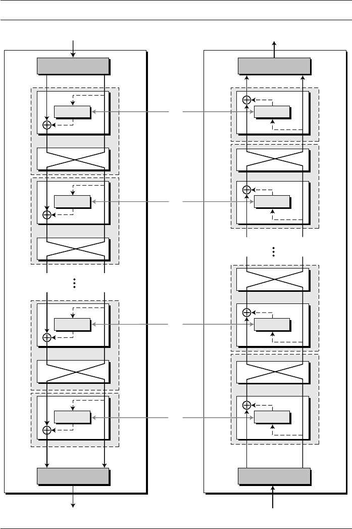
168 CHAPTER 6 DATA ENCRYPTION STANDARD (DES)
Figure 6.9 DES cipher and reverse cipher for the first approach
f
f
f
f
f
f
f
f
64-bit plaintext
L
0
R
0
L
16
R
16
Round 1
Round 1
Round 2
Round 2
Round 16
Round 16
Initial permutation Final permutation
Final permutation Initial permutation
64-bit ci
p
hertext
Encryption
Decryption
L
0
L
16
R
0
R
16
64-bit plaintext
64-bit ci
p
hertext
Round 15
Round 15
K
1
K
15
K
16
K
2

SECTION 6.2 DES STRUCTURE 169
Although the rounds are not aligned, the elements (mixer or swapper) are
aligned. We proved in Chapter 5 that a mixer is a self-inverse; so is a swapper.
The final and initial permutations are also inverses of each other. The left section of
the plaintext at the encryption site, L
0
, is enciphered as L
16
at the encryption site; L
16
at the decryption is deciphered as L
0
at the decryption site. The situation is the same
with R
0
and R
16
.
A very important point we need to remember about the ciphers is that the round
keys (K
1
to K
16
) should be applied in the reverse order. At the encryption site, round 1
uses K
1
and round 16 uses K
16
; at the decryption site, round 1 uses K
16
and round 16
uses K
1
.
Algorithm
Algorithm 6.1 gives the pseudocode for the cipher and four corresponding routines in
the first approach. The codes for the rest of the routines are left as exercises.
In the first approach, there is no swapper in the last round.
Algorithm 6.1
Pseudocode for DES cipher
Cipher (plainBlock[64], RoundKeys[16, 48], cipherBlock[64])
{
permute (64, 64, plainBlock, inBlock, InitialPermutationTable)
split (64, 32, inBlock, leftBlock, rightBlock)
for (round = 1 to 16)
{
mixer (leftBlock, rightBlock, RoundKeys[round])
if (round!=16) swapper (leftBlock, rightBlock)
}
combine (32, 64, leftBlock, rightBlock, outBlock)
permute (64, 64, outBlock, cipherBlock, FinalPermutationTable)
}
mixer (leftBlock[32], rightBlock[32], RoundKey[48])
{
copy (32, rightBlock, T1)
function (T1, RoundKey, T2)
exclusiveOr (32, leftBlock, T2, T3)
copy (32, T3, rightBlock)
}
swapper (leftBlock[32], rigthBlock[32])
{
copy (32, leftBlock, T)
copy (32, rightBlock, leftBlock)
copy (32, T, rightBlock)
}

170 CHAPTER 6 DATA ENCRYPTION STANDARD (DES)
Alternative Approach
In the first approach, round 16 is different from other rounds; there is no swapper in this
round. This is needed to make the last mixer in the cipher and the first mixer in the
reverse cipher aligned. We can make all 16 rounds the same by including one swapper
to the 16th round and add an extra swapper after that (two swappers cancel the effect of
each other). We leave the design for this approach as an exercise.
Key Generation
The round-key generator creates sixteen 48-bit keys out of a 56-bit cipher key. However,
the cipher key is normally given as a 64-bit key in which 8 extra bits are the parity bits,
which are dropped before the actual key-generation process, as shown in Figure 6.10.
Parity Drop
The preprocess before key expansion is a compression permutation that we call parity
bit drop. It drops the parity bits (bits 8, 16, 24, 32, …, 64) from the 64-bit key and per-
mutes the rest of the bits according to Table 6.12. The remaining 56-bit value is the
actual cipher key which is used to generate round keys. The parity drop permutation (a
compression P-box) is shown in Table 6.12.
function (inBlock[32], RoundKey[48], outBlock[32])
{
permute (32, 48, inBlock, T1, ExpansionPermutationTable)
exclusiveOr (48, T1, RoundKey, T2)
substitute (T2, T3, SubstituteTables)
permute (32, 32, T3, outBlock, StraightPermutationTable)
}
substitute (inBlock[32], outBlock[48], SubstitutionTables[8, 4, 16])
{
for (i = 1 to 8)
{
row ← 2 × inBlock[i × 6 + 1] + inBlock [i × 6 + 6]
col ← 8 × inBlock[i × 6 + 2] + 4 × inBlock[i × 6 + 3] +
2 × inBlock[i × 6 + 4] + inBlock[i × 6 + 5]
value = SubstitutionTables [i][row][col]
outBlock[[i × 4 + 1] ← value / 8; value ← value mod 8
outBlock[[i × 4 + 2] ← value / 4; value ← value mod 4
outBlock[[i × 4 + 3] ← value / 2; value ← value mod 2
outBlock[[i × 4 + 4] ← value
}
}
Algorithm 6.1 Pseudocode for DES cipher (continued)

SECTION 6.2 DES STRUCTURE 171
Figure 6.10 Key generation
Table 6.12 Parity-bit drop table
57 49 41 33 25 17 09 01
58 50 42 34 26 18 10 02
59 51 43 35 27 19 11 03
60 52 44 36 63 55 47 39
31 23 15 07 62 54 46 38
30 22 14 06 61 53 45 37
29 21 13 05 28 20 12 04
28 bits
28 bits
Key with
parity bits
Round key 2
Round key 16
Cipher key (56 bits)
(64 bits)
Round-Key Generator
Shifting
Parity drop
28 bits 28 bits
48 bits
Round key 1
Compression
P-box
Shift left Shift left
28 bits 28 bits
48 bits
Compression
P-box
Shift left
Shift left
28 bits 28 bits
48 bits
Compression
P-box
Shift left Shift left
1, 2, 9, 16 one bit
Others
two bits
Shift
Rounds

172 CHAPTER 6 DATA ENCRYPTION STANDARD (DES)
Shift Left
After the straight permutation, the key is divided into two 28-bit parts. Each part is
shifted left (circular shift) one or two bits. In rounds 1, 2, 9, and 16, shifting is one bit;
in the other rounds, it is two bits. The two parts are then combined to form a 56-bit part.
Table 6.13 shows the number of shifts for each round.
Compression Permutation
The compression permutation (P-box) changes the 58 bits to 48 bits, which are used as
a key for a round. The compression permutation is shown in Table 6.14.
Algorithm
Let us write a simple algorithm to create round keys from the key with parity bits.
Algorithm 6.2 uses several routines from Algorithm 6.1. The new one is the shiftLeft
routine, for which the code is given. Note that T is a temporary block.
Table 6.13
Number of bit shifts
Round 1 2 3 4 5 6 7 8 9 10 11 12 13 14 15 16
Bit shifts 1 1 2 2 2 2 2 2 1 2 2 2 2 2 2 1
Table 6.14 Key-compression table
14 17 11 24 01 05 03 28
15 06 21 10 23 19 12 04
26 08 16 07 27 20 13 02
41 52 31 37 47 55 30 40
51 45 33 48 44 49 39 56
34 53 46 42 50 36 29 32
Algorithm 6.2 Algorithm for round-keys generation
Key_Generator (keyWithParities[64], RoundKeys[16, 48], ShiftTable[16])
{
permute (64, 56, keyWithParities, cipherKey, ParityDropTable)
split (56, 28, cipherKey, leftKey, rightKey)
for (round = 1 to 16)
{
shiftLeft (leftKey, ShiftTable[round])
shiftLeft (rightKey, ShiftTable[round])
combine (28, 56, leftKey, rightKey, preRoundKey)
permute (56, 48, preRoundKey, RoundKeys[round], KeyCompressionTable)
}
}

SECTION 6.2 DES STRUCTURE 173
Examples
Before analyzing DES, let us look at some examples to see the how encryption and
decryption change the value of bits in each round.
Example 6.5
We choose a random plaintext block and a random key, and determine what the ciphertext block
would be (all in hexadecimal):
Let us show the result of each round and the text created before and after the rounds.
Table 6.15 first shows the result of steps before starting the round. The plaintext goes through
shiftLeft (block[28], numOfShifts)
{
for (i = 1 to numOfShifts)
{
T ← block[1]
for (j = 2 to 28)
{
block [j
−1] ← block [j]
}
block[28] ← T
}
}
Plaintext: 123456ABCD132536 Key: AABB09182736CCDD
CipherText: C0B7A8D05F3A829C
Table 6.15 Trace of data for Example 6.5
Plaintext: 123456ABCD132536
After initial permutation:14A7D67818CA18AD
After splitting: L
0
=14A7D678 R
0
=18CA18AD
Round Left Right Round Key
Round 1
Round 2
Round 3
Round 4
18CA18AD
5A78E394
4A1210F6
B8089591
5A78E394
4A1210F6
B8089591
236779C2
194CD072DE8C
4568581ABCCE
06EDA4ACF5B5
DA2D032B6EE3
Algorithm 6.2 Algorithm for round-keys generation (continued)

174 CHAPTER 6 DATA ENCRYPTION STANDARD (DES)
the initial permutation to create completely different 64 bits (16 hexadecimal digit). After this
step, the text is split into two halves, which we call L
0
and R
0
. The table shows the result of
16 rounds that involve mixing and swapping (except for the last round). The results of the last
rounds (L
16
and R
16
) are combined. Finally the text goes through final permutation to create
the ciphertext.
Some points are worth mentioning here. First, the right section out of each
round is the same as the left section out of the next round. The reason is that the
right section goes through the mixer without change, but the swapper moves it to the
left section. For example, R
1
passes through the mixer of the second round without
change, but then it becomes L
2
because of the swapper. The interesting point is that
we do not have a swapper at the last round. That is why R
15
becomes R
16
instead of
becoming L
16
.
Example 6.6
Let us see how Bob, at the destination, can decipher the ciphertext received from Alice using
the same key. We have shown only a few rounds to save space. Table 6.16 shows some interest-
ing points. First, the round keys should be used in the reverse order. Compare Table 6.15 and
Table 6.16. The round key for round 1 is the same as the round key for round 16. The values of
L
0
and R
0
during decryption are the same as the values of L
16
and R
16
during encryption. This
is the same with other rounds. This proves not only that the cipher and the reverse cipher are
inverses of each other in the whole, but also that each round in the cipher has a corresponding
reverse round in the reverse cipher. The result proves that the initial and final permutation steps
are also inverses of each other.
Round 5
Round 6
Round 7
Round 8
Round 9
Round 10
Round 11
Round 12
Round 13
Round 14
Round 15
Round 16
236779C2
A15A4B87
2E8F9C65
A9FC20A3
308BEE97
10AF9D37
6CA6CB20
FF3C485F
22A5963B
387CCDAA
BD2DD2AB
19BA9212
A15A4B87
2E8F9C65
A9FC20A3
308BEE97
10AF9D37
6CA6CB20
FF3C485F
22A5963B
387CCDAA
BD2DD2AB
CF26B472
CF26B472
69A629FEC913
C1948E87475E
708AD2DDB3C0
34F822F0C66D
84BB4473DCCC
02765708B5BF
6D5560AF7CA5
C2C1E96A4BF3
99C31397C91F
251B8BC717D0
3330C5D9A36D
181C5D75C66D
After combination: 19BA9212CF26B472
Ciphertext: C0B7A8D05F3A829C (after final permutation)
Table 6.15 Trace of data for Example 6.5 (continued)

SECTION 6.3 DES ANALYSIS 175
6.3 DES ANALYSIS
Critics have used a strong magnifier to analyze DES. Tests have been done to measure
the strength of some desired properties in a block cipher. The elements of DES have
gone through scrutinies to see if they have met the established criteria. We discuss some
of these in this section.
Properties
Two desired properties of a block cipher are the avalanche effect and the completeness.
Avalanche Effect
Avalanche effect means a small change in the plaintext (or key) should create a significant
change in the ciphertext. DES has been proved to be strong with regard to this property.
Example 6.7
To check the avalanche effect in DES, let us encrypt two plaintext blocks (with the same key) that
differ only in one bit and observe the differences in the number of bits in each round.
Although the two plaintext blocks differ only in the rightmost bit, the ciphertext blocks dif-
fer in 29 bits. This means that changing approximately 1.5 percent of the plaintext creates a
change of approximately 45 percent in the ciphertext. Table 6.17 shows the change in each round.
It shows that significant changes occur as early as the third round.
Table 6.16 Trace of data for Example 6.6
Ciphertext: C0B7A8D05F3A829C
After initial permutation: 19BA9212CF26B472
After splitting: L
0
=19BA9212 R
0
=CF26B472
Round Left Right Round Key
Round 1
Round 2
. . .
Round 15
Round 16
CF26B472
BD2DD2AB
...
5A78E394
14A7D678
BD2DD2AB
387CCDAA
...
18CA18AD
18CA18AD
181C5D75C66D
3330C5D9A36D
...
4568581ABCCE
194CD072DE8C
After combination: 14A7D67818CA18AD
Plaintext:123456ABCD132536 (after final permutation)
Plaintext: 0000000000000000 Key: 22234512987ABB23
Ciphertext: 4789FD476E82A5F1
Plaintext: 0000000000000001
Key: 22234512987ABB23
Ciphertext: 0A4ED5C15A63FEA3

176 CHAPTER 6 DATA ENCRYPTION STANDARD (DES)
Completeness effect
Completeness effect means that each bit of the ciphertext needs to depend on many
bits on the plaintext. The diffusion and confusion produced by P-boxes and S-boxes in
DES, show a very strong completeness effect.
Design Criteria
The design of DES was revealed by IBM in 1994. Many tests on DES have proved that
it satisfies some of the required criteria as claimed. We briefly discuss some of these
design issues.
S-Boxes
We have discussed the general design criteria for S-boxes in Chapter 5; we only discuss
the criteria selected for DES here. The design provides confusion and diffusion of bits
from each round to the next. According to this revelation and some research, we can
mention several properties of S-boxes.
1. The entries of each row are permutations of values between 0 and 15.
2. S-boxes are nonlinear. In other words, the output is not an affine transformation of
the input. See Chapter 5 for discussion on the linearity of S-boxes.
3. If we change a single bit in the input, two or more bits will be changed in the output.
4. If two inputs to an S-box differ only in two middle bits (bits 3 and 4), the output
must differ in at least two bits. In other words, S(x) and S(x ⊕ 001100) must differ
in at least two bits where x is the input and S(x) is the output.
5. If two inputs to an S-box differ in the first two bits (bits 1 and 2) and are the same
in the last two bits (5 and 6), the two outputs must be different. In other words,
we need to have the following relation S(x) ≠ S(x ⊕ 11bc00), in which b and c are
arbitrary bits.
6. There are only 32 6-bit input-word pairs (x
i
and x
j
), in which x
i
⊕ x
j
≠ (000000)
2
.
These 32 input pairs create 32 4-bit output-word pairs. If we create the difference
between the 32 output pairs, d = y
i
⊕ y
j
, no more than 8 of these d’s should be the
same.
7. A criterion similar to # 6 is applied to three S-boxes.
8. In any S-box, if a single input bit is held constant (0 or 1) and the other bits are
changed randomly, the differences between the number of 0s and 1s are minimized.
P-Boxes
Between two rows of S-boxes (in two subsequent rounds), there are one straight P-box
(32 to 32) and one expansion P-box (32 to 48). These two P-boxes together provide
diffusion of bits. We have discussed the general design principle of P-boxes in
Table 6.17
Number of bit differences for Example 6.7
Rounds 1 2 3 4 5 6 7 8 9 10 11 12 13 14 15 16
Bit differences 1 6 20 29 30 33 32 29 32 39 33 28 30 31 30 29
SECTION 6.3 DES ANALYSIS 177
Chapter 5. Here we discuss only the ones applied to the P-boxes used inside the DES
function. The following criteria were implemented in the design of P-boxes to
achieve this goal:
1. Each S-box input comes from the output of a different S-box (in the previous
round).
2. No input to a given S-box comes from the output from the same box (in the previous
round).
3. The four outputs from each S-box go to four different S-boxes (in the next round).
4. No two output bits from an S-box go to the same S-box (in the next round).
5. If we number the eight S-boxes, S
1
, S
2
, …, S
8
,
a. An output of S
j−2
goes to one of the first two bits of S
j
(in the next round).
b. An output bit from S
j −1
goes to one of the last two bits of S
j
(in the next round).
c. An output of S
j +1
goes to one of the two middle bits of S
j
(in the next round).
6. For each S-box, the two output bits go to the first or last two bits of an S-box in the
next round. The other two output bits go to the middle bits of an S-box in the next
round.
7. If an output bit from S
j
goes to one of the middle bits in S
k
(in the next round), then
an output bit from S
k
cannot go to the middle bit of S
j
. If we let j = k, this implies
that none of the middle bits of an S-box can go to one of the middle bits of the
same S-box in the next round.
Number of Rounds
DES uses sixteen rounds of Feistel ciphers. It has been proved that after eight rounds,
each ciphertext is a function of every plaintext bit and every key bit; the ciphertext is
thoroughly a random function of plaintext and ciphertext. Therefore, it looks like
eight rounds should be enough. However, experiments have found that DES versions
with less than sixteen rounds are even more vulnerable to known-plaintext attacks
than brute-force attack, which justifies the use of sixteen rounds by the designers
of DES.
DES Weaknesses
During the last few years critics have found some weaknesses in DES.
Weaknesses in Cipher Design
We will briefly mention some weaknesses that have been found in the design of the
cipher.
S-boxes At least three weaknesses are mentioned in the literature for S-boxes.
1. In S-box 4, the last three output bits can be derived in the same way as the first out-
put bit by complementing some of the input bits.
2. Two specifically chosen inputs to an S-box array can create the same output.
3. It is possible to obtain the same output in a single round by changing bits in only
three neighboring S-boxes.

178 CHAPTER 6 DATA ENCRYPTION STANDARD (DES)
P-boxes One mystery and one weakness were found in the design of P-boxes:
1. It is not clear why the designers of DES used the initial and final permutations;
these have no security benefits.
2. In the expansion permutation (inside the function), the first and fourth bits of every
4-bit series are repeated.
Weakness in the Cipher Key
Several weaknesses have been found in the cipher key.
Key Size Critics believe that the most serious weakness of DES is in its key size
(56 bits). To do a brute-force attack on a given ciphertext block, the adversary needs
to check 2
56
keys.
a. With available technology, it is possible to check one million keys per second.
This means that we need more than two thousand years to do brute-force attacks
on DES using only a computer with one processor.
b. If we can make a computer with one million chips (parallel processing), then
we can test the whole key domain in approximately 20 hours. When DES was
introduced, the cost of such a computer was over several million dollars, but the
cost has dropped rapidly. A special computer was built in 1998 that found the
key in 112 hours.
c. Computer networks can simulate parallel processing. In 1977 a team of
researchers used 3500 computers attached to the Internet to find a key challenged
by RSA Laboratories in 120 days. The key domain was divided among all of
these computers, and each computer was responsible to check the part of the
domain.
d. If 3500 networked computers can find the key in 120 days, a secret society with
42,000 members can find the key in 10 days.
The above discussion shows that DES with a cipher key of 56 bits is not safe enough to
be used comfortably. We will see later in the chapter that one solution is to use triple
DES (3DES) with two keys (112 bits) or triple DES with three keys (168 bits).
Weak Keys Four out of 2
56
possible keys are called weak keys. A weak key is the
one that, after parity drop operation (using Table 6.12), consists either of all 0s, all 1s,
or half 0s and half 1s. These keys are shown in Table 6.18.
The round keys created from any of these weak keys are the same and have the
same pattern as the cipher key. For example, the sixteen round keys created from
the first key is all made of 0s; the one from the second is made of half 0s and half 1s.
Table 6.18
Weak keys
Keys before parities drop (64 bits) Actual key (56 bits)
0101 0101 0101 0101 0000000 0000000
1F1F 1F1F 0E0E 0E0E 0000000 FFFFFFF
E0E0 E0E0 F1F1 F1F1 FFFFFFF 0000000
FEFE FEFE FEFE FEFE FFFFFFF FFFFFFF

SECTION 6.3 DES ANALYSIS 179
The reason is that the key-generation algorithm first divides the cipher key into two
halves. Shifting or permutation of a block does not change the block if it is made of
all 0s or all 1s.
What is the disadvantage of using a weak key? If we encrypt a block with a weak key
and subsequently encrypt the result with the same weak key, we get the original block.
The process creates the same original block if we decrypt the block twice. In other words,
each weak key is the inverse of itself E
k
(E
k
(P)) = P, as shown in Figure 6.11.
Weak keys should be avoided because the adversary can easily try them on the
intercepted ciphertext. If after two decryptions the result is the same, the adversary has
found the key.
Example 6.8
Let us try the first weak key in Table 6.18 to encrypt a block two times. After two encryptions
with the same key the original plaintext block is created. Note that we have used the encryption
algorithm two times, not one encryption followed by another decryption.
Semi-weak Keys There are six key pairs that are called semi-weak keys. These six
pairs are shown in Table 6.19 (64-bit format before dropping the parity bits).
A semi-weak key creates only two different round keys and each of them is
repeated eight times. In addition, the round keys created from each pair are the same
Figure 6.11 Double encryption and decryption with a weak key
Key: 0x0101010101010101
Plaintext: 0x1234567887654321 Ciphertext: 0x814FE938589154F7
Key: 0x0101010101010101
Plaintext: 0x814FE938589154F7 Ciphertext: 0x1234567887654321
A weak key
DES
cipher
64-bit text
64-bit text
P
P
DES
inverse cipher
64-bit text
64-bit text
C
C
DES
cipher
DES
inverse cipher
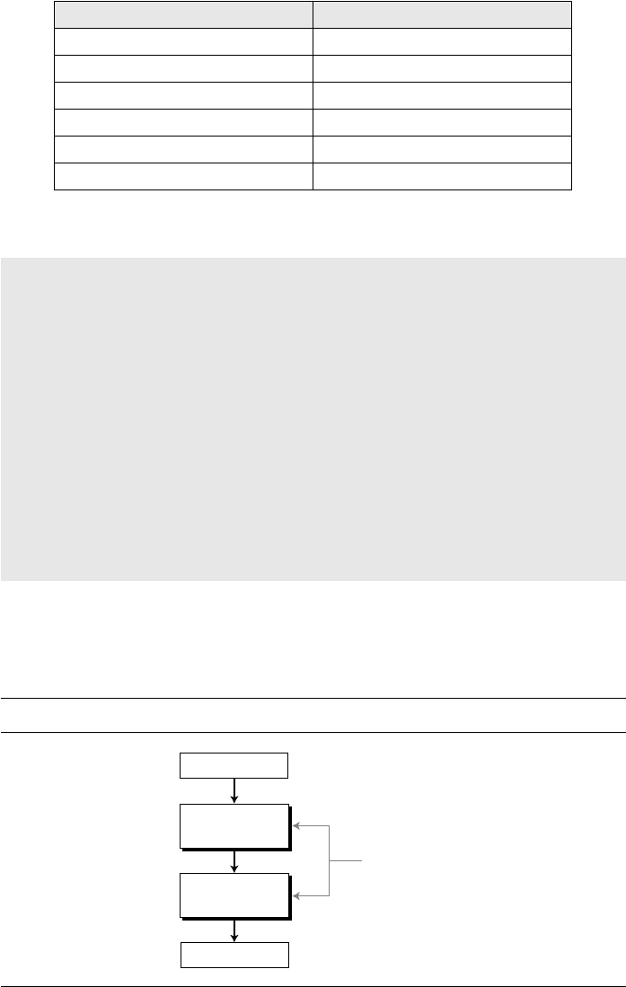
180 CHAPTER 6 DATA ENCRYPTION STANDARD (DES)
with different orders. To show the idea, we have created the round keys from the first
pairs as shown below:
As the list shows, there are eight equal round keys in each semi-weak key. In addi-
tion, round key 1 in the first set is the same as round key 16 in the second; round key 2
in the first is the same as round key 15 in the second; and so on. This means that the
keys are inverses of each other , as shown in Figure 6.12.
Table 6.19
Semi-weak keys
First key in the pair Second key in the pair
01FE 01FE 01FE 01FE FE01 FE01 FE01 FE01
1FE0 1FE0 0EF1 0EF1 E01F E01F F10E F10E
01E0 01E1 01F1 01F1 E001 E001 F101 F101
1FFE 1FFE 0EFE 0EFE FE1F FE1F FE0E FE0E
011F 011F 010E 010E 1F01 1F01 0E01 0E01
E0FE E0FE F1FE F1FE FEE0 FEE0 FEF1 FEF1
Round key 1
Round key 2
Round key 3
Round key 4
Round key 5
Round key 6
Round key 7
Round key 8
Round key 9
Round key 10
Round key 11
Round key 12
Round key 13
Round key 14
Round key 15
Round key 16
9153E54319BD
6EAC1ABCE642
6EAC1ABCE642
6EAC1ABCE642
6EAC1ABCE642
6EAC1ABCE642
6EAC1ABCE642
6EAC1ABCE642
9153E54319BD
9153E54319BD
9153E54319BD
9153E54319BD
9153E54319BD
9153E54319BD
9153E54319BD
6EAC1ABCE642
6EAC1ABCE642
9153E54319BD
9153E54319BD
9153E54319BD
9153E54319BD
9153E54319BD
9153E54319BD
9153E54319BD
6EAC1ABCE642
6EAC1ABCE642
6EAC1ABCE642
6EAC1ABCE642
6EAC1ABCE642
6EAC1ABCE642
6EAC1ABCE642
9153E54319BD
Figure 6.12 A pair of semi-weak keys in encryption and decryption
E
k
2
E
k
1
P( )( ) P
DES
cipher
A pair of
semi-weak keys
DES
cipher
64-bit text
64-bit text
P
P
k
1
k
2

SECTION 6.4 MULTIPLE DES 181
Possible Weak Keys There are also 48 keys that are called possible weak keys. A
possible weak key is a key that creates only four distinct round keys; in other words, the
sixteen round keys are divided into four groups and each group is made of four equal
round keys.
Example 6.9
What is the probability of randomly selecting a weak, a semi-weak, or a possible weak key?
Solution
DES has a key domain of 2
56
. The total number of the above keys are 64 (4 + 12 + 48). The prob-
ability of choosing one of these keys is 8.8
× 10
−
16
, almost impossible.
Key Complement In the key domain (2
56
), definitely half of the keys are comple-
ment of the other half. A key complement can be made by inverting (changing 0 to 1 or
1 to 0) each bit in the key. Does a key complement simplify the job of the cryptanalysis?
It happens that it does. Eve can use only half of the possible keys (2
55
) to perform
brute-force attack. This is because
In other words, if we encrypt the complement of plaintext with the complement of
the key, we get the complement of the ciphertext. Eve does not have to test all 2
56
pos-
sible keys, she can test only half of them and then complement the result.
Example 6.10
Let us test the claim about the complement keys. We have used an arbitrary key and plaintext to
find the corresponding ciphertext. If we have the key complement and the plaintext, we can
obtain the complement of the previous ciphertext (Table 6.20).
Key Clustering Key clustering refers to the situation in which two or more different
keys can create the same ciphertext from the same plaintext. Obviously, each pair of the
semi-weak keys is a key cluster. However, no more clusters have been found for the
DES. Future research may reveal some more.
6.4 MULTIPLE DES
As we have seen, the major criticism of DES regards its key length. With available
technology and the possibility of parallel processing, a brute-force attack on DES is
feasible. One solution to improve the security of DES is to abandon DES and design a
new cipher. We will see this solution in Chapter 7 with the advent of AES. The second
C = E (K, P) → C
= E (K, P)
Table 6.20 Results for Example 6.10
Original Complement
Key 1234123412341234 EDCBEDCBEDCBEDCB
Plaintext 12345678ABCDEF12 EDCBA987543210ED
Ciphertext E112BE1DEFC7A367 1EED41E210385C98

182 CHAPTER 6 DATA ENCRYPTION STANDARD (DES)
solution is to use multiple (cascaded) instances of DES with multiple keys; this solu-
tion, which has been used for a while, does not require an investment in new software
and hardware. We study the second solution here.
As we learned in Chapter 5, a substitution that maps every possible input to
every possible output is a group, with the mappings as the set elements and the com-
position as the operator. In this case, using two consecutive mappings is useless
because we can always find the third mapping that is equivalent to the composition of
the two (closure property). This means that if DES is a group, using double DES with
two keys k
1
and k
2
is useless because a single DES with key k
3
does the same thing
(Figure 6.13).
Fortunately DES is not a group, based on the following two arguments:
a. The number of possible inputs or outputs in DES is N = 2
64
. This means that
we have N! = (2
64
)! = 10
347,380,000,000,000,000,000
mappings. One way to make
DES a group is to make it support all of these mappings with the key size of
log
2
(2
64
!) ≈ 2
70
bits. But we know that the key length in DES is only 56 bits
(only a small fraction of this huge key).
b. Another way for DES to be a group is for the set of mappings to be a subset of the
set in the sense of the first argument, but it has been proved that none of the sub-
groups created from the group in the first argument, have a key size of 56 bits.
If DES is not a group, it is highly improbable that we can find a key, k
3
, such that
This means that we can use double or triple DES to increase the key size.
Double DES
The first approach is to use double DES (2DES). In this approach, we use two
instances of DES ciphers for encryption and two instances of reverse ciphers for
decryption. Each instance uses a different key, which means that the size of the key is
now doubled (112 bits). However, double DES is vulnerable to a known-plain text
attack, as discussed in the next section.
Figure 6.13 Composition of mapping
E
k2
(E
k1
(P)) = E
k3
(P)
First mapping
(using k
1
)
All possible
2
64
blocks
All possible
2
64
blocks
All possible
2
64
blocks
Second mapping
(using k
2
)
Third mapping
(using k
3
)

SECTION 6.4 MULTIPLE DES 183
Meet-in-the-Middle Attack
At first glance, it looks like double DES increases the number of tests for key search
from 2
56
(in single DES)
to 2
112
(in double DES). However, using a known-plaintext
attack called meet-in-the-middle attack proves that double DES improves this vulner-
ability slightly (to 2
57
tests), but not tremendously (to 2
112
). Figure 6.14 shows the dia-
gram for the double DES. Alice uses two keys, k
1
and k
2
, to decrypt plaintext P into
ciphertext C; Bob uses ciphertext C and two keys, k
2
and k
1
,
to recover P.
The point is that the middle text, the text created by the first encryption or first
decryption, M, should be the same for encryption and decryption to work. In other words,
we have two relationships:
Assume that Eve has intercepted a previous pair P and C (known-plaintext attack).
Based on the first relationship mentioned above, Eve encrypts P using all possible val-
ues (2
56
) of k
1
and records all values obtained for M. Based on the second relationship
mentioned above, Eve decrypts C using all possible values (2
56
) of k
2
and records all
values obtained for M. Eve creates two tables sorted by M values. She then compares
the values for M until she finds those pairs of k
1
and k
2
for which the value of M is the
same in both tables as shown in Figure 6.15. Note that there must be at least one pair
because she is doing exhaustive search on the combination of two keys.
1. If there is only one match, Eve has found the two keys (k
1
and k
2
). If there is more
than one candidate, Eve moves to the next step.
2. She takes another intercepted plaintext-ciphertext pair and uses each of the candidate
key pairs to see if she can get the ciphertext from the plaintext. If she finds more than
one candidate key pair, she repeats step 2 until she finally finds a unique pair.
Figure 6.14 Meet-in-the-middle attack for double DES
and
Decr
y
ption
DES
reverse cipher
DES
reverse cipher
64-bit plaintext
64-bit ciphertext
64-bit middle text
P
C
M
k
1
k
2
Encryption
DES
cipher
DES
cipher
64-bit plaintext
P
64-bit ciphertext
C
64-bit middle textM
M E
k
1
P( ) M D
k
2
C( )

184 CHAPTER 6 DATA ENCRYPTION STANDARD (DES)
It has been proved that after applying the second step to a few intercepted plaintext-
ciphertext pairs, the keys are found. This means that instead of using 2
112
key-search
tests, Eve uses 2
56
key-search tests two times (with some more tests if more than a sin-
gle candidate is found in the first step). In other words, moving from single DES to
double DES, we have increased the strength from 2
56
to 2
57
(not to 2
112
as it is believed
superficially).
Triple DES
To improve the security of DES, triple DES (3DES) was proposed. This uses three
stages of DES for encryption and decryption. Two versions of triple DES are in use
today: triple DES with two keys and triple DES with three keys.
Triple DES with Two Keys
In triple DES with two keys, there are only two keys: k
1
and k
2
. The first and the third
stages use k
1
; the second stage uses k
2
.
To make triple DES compatible with single
DES, the middle stage uses decryption (reverse cipher) in the encryption site and
encryption (cipher) in the decryption site. In this way, a message encrypted with single
DES with key k can be decrypted with triple DES if k
1
= k
2
= k. Although triple DES
with two keys is also vulnerable to a known-plaintext attack, it is much stronger than
double DES. It has been adopted by the banking industry. Figure 6.16 shows triple DES
with two keys.
Triple DES with Three Keys
The possibility of known-plaintext attacks on triple DES with two keys has enticed
some applications to use triple DES with three keys. Although the algorithm can use
three DES cipher stages at the encryption site and three reverse cipher stages at the
decryption site, to be compatible with single DES, the encryption site uses EDE and the
decryption site uses DED (E stands for encryption and D stands for decryption). Com-
patibility with single DES is provided by letting k
1
= k and setting k
2
and k
3
to the
same arbitrary key chosen by the receiver. Triple DES with three keys is used by many
applications such as PGP (See Chapter 16).
Figure 6.15 Tables for meet-in-the-middle attack
k
1
k
2
M
M = E
k
1
(P) M = D
k
2
(C)
Find equal M’s and record corresponding k
1
and k
2
M

SECTION 6.5 SECURITY OF DES 185
6.5 SECURITY OF DES
DES, as the first important block cipher, has gone through much scrutiny. Among the
attempted attacks, three are of interest: brute-force, differential cryptanalysis, and linear
cryptanalysis.
Brute-Force Attack
We have discussed the weakness of short cipher key in DES. Combining this weakness
with the key complement weakness, it is clear that DES can be broken using 2
55
encryptions. However, today most applications use either 3DES with two keys (key
size of 112) or 3DES with three keys (key size of 168). These two multiple-DES ver-
sions make DES resistant to brute-force attacks.
Differential Cryptanalysis
We discussed the technique of differential cryptanalysis on modern block ciphers in
Chapter 5. DES is not immune to that kind of attack. However, it has been revealed that
the designers of DES already knew about this type of attack and designed S-boxes and
chose 16 as the number of rounds to make DES specifically resistant to this type of
attack. Today, it has been shown that DES can be broken using differential cryptanalysis
if we have 2
47
chosen plaintexts or 2
55
known plaintexts. Although this looks more effi-
cient than a brute-force attack, finding 2
47
chosen plaintexts or 2
55
know plaintexts is
impractical. Therefore, we can say that DES is resistant to differential cryptanalysis. It
has also been shown that increasing the number of rounds to 20 require more than 2
64
chosen plaintexts for this attack, which is impossible because the possible number of
plaintext blocks in DES is only 2
64
.
Figure 6.16 Triple DES with two keys
DES
reverse cipher
DES
cipher
DES
reverse cipher
64-bit plaintext
64-bit ciphertext
P P
C C
Decr
y
ption
k
1
k
1
Encryption
k
2
DES
cipher
DES
reverse cipher
DES
cipher
64-bit plaintext
64-bit ciphertext

186 CHAPTER 6 DATA ENCRYPTION STANDARD (DES)
Linear Cryptanalysis
We discussed the technique of linear cryptanalysis on modern block ciphers in Chapter 5.
Linear cryptanalysis is newer than differential cryptanalysis. DES is more vulnerable to
linear cryptanalysis than to differential cryptanalysis, probably because this type of attack
was not known to the designers of DES. S-boxes are not very resistant to linear cryptanal-
ysis. It has been shown that DES can be broken using 2
43
pairs of known plaintexts. How-
ever, from the practical point of view, finding so many pairs is very unlikely.
6.6 RECOMMENDED READING
The following books and websites provide more details about subjects discussed in this
chapter. The items enclosed in brackets […] refer to the reference list at the end of the book.
Books
[Sta06], [Sti06], [Rhe03], [Sal03], [Mao04], and [TW06] discuss DES.
WebSites
The following websites give more information about topics discussed in this chapter.
6.7 KEY TERMS
We show an example of DES differential cryptanalysis in Appendix N.
We show an example of DES linear cryptanalysis in Appendix N.
http://www.itl.nist.gov/fipspubs/fip46-2.htm
www.nist.gov/director/prog-ofc/report01-2.pdf
www.engr.mun.ca/~howard/PAPERS/ldc_tutorial.ps
islab.oregonstate.edu/koc/ece575/notes/dc1.pdf
homes.esat.kuleuven.be/~abiryuko/Cryptan/matsui_des
http://nsfsecurity.pr.erau.edu/crypto/lincrypt.html
avalanche effect National Security Agency (NSA)
completeness effect parity bit drop
Data Encryption Standard (DES) possible weak keys
double DES (2DES) round-key generator
Federal Information Processing Standard
(FIPS)
semi-weak keys
triple DES (3DES)
key complement triple DES with three keys
meet-in-the-middle attack triple DES with two keys
National Institute of Standards and Technology
(NIST)
weak keys

SECTION 6.9 PRACTICE SET 187
6.8 SUMMARY
❏ The Data Encryption Standard (DES) is a symmetric-key block cipher published
by the National Institute of Standards and Technology (NIST) as FIPS 46 in the
Federal Register.
❏ At the encryption site, DES takes a 64-bit plaintext and creates a 64-bit ciphertext.
At the decryption site, DES takes a 64-bit ciphertext and creates a 64-bit block of
plaintext. The same 56-bit cipher key is used for both encryption and decryption.
❏ The encryption process is made of two permutations (P-boxes), which we call
initial and final permutations, and sixteen Feistel rounds. Each round of DES is a
Feistel cipher with two elements (mixer and swapper). Each of these elements is
invertible.
❏ The heart of DES is the DES function. The DES function applies a 48-bit key
to the rightmost 32 bits to produce a 32-bit output. This function is made up of
four operations: an expansion permutation, a whitener (that adds key), a group
of S-boxes, and a straight permutation.
❏ The round-key generator creates sixteen 48-bit keys out of a 56-bit cipher key.
However, the cipher key is normally presented as a 64-bit key in which 8 extra bits
are the parity bits, which are dropped before the actual key-generation process.
❏ DES has shown a good performance with respect to avalanche and completeness
effects. Areas of weaknesses in DES include cipher design (S-boxes and P-boxes)
and cipher key (length, weak keys, semi-weak keys, possible weak keys, and key
complements).
❏ Since DES is not a group, one solution to improve the security of DES is to use mul-
tiple DES (double and triple DES). Double DES is vulnerable to meet-in-the-middle
attack, so triple DES with two keys or three keys is common in applications.
❏ The design of S-boxes and number of rounds makes DES almost immune from the
differential cryptanalysis. However, DES is vulnerable to linear cryptanalysis if the
adversary can collect enough known plaintexts.
6.9 PRACTICE SET
Review Questions
1. What is the block size in DES? What is the cipher key size in DES? What is the
round-key size in DES?
2. What is the number of rounds in DES?
3. How many mixers and swappers are used in the first approach of making encryption
and decryption inverses of each other? How many are used in the second approach?
4. How many permutations are used in a DES cipher algorithm? How many permuta-
tions are used in the round-key generator?
5. How many exclusive-or operations are used in the DES cipher?
6. Why does the DES function need an expansion permutation?
188 CHAPTER 6 DATA ENCRYPTION STANDARD (DES)
7. Why does the round-key generator need a parity drop permutation?
8. What is the difference between a weak key, a semi-weak key, and a possible weak key?
9. What is double DES? What kind of attack on double DES makes it useless?
10. What is triple DES? What is triple DES with two keys? What is triple DES with
three keys?
Exercises
11. Answer the following questions about S-boxes in DES:
a. Show the result of passing 110111 through S-box 3.
b. Show the result of passing 001100 through S-box 4.
c. Show the result of passing 000000 through S-box 7.
d. Show the result of passing 111111 through S-box 2.
12. Draw the table to show the result of passing 000000 through all 8 S-boxes. Do you
see a pattern in the outputs?
13. Draw the table to show the result of passing 111111 through all 8 S-boxes. Do you
see a pattern in the outputs?
14. Check the third criterion for S-box 3 using the following pairs of inputs.
a. 000000 and 000001
b. 111111 and 111011
15. Check the fourth design criterion for S-box 2 using the following pairs of inputs.
a. 001100 and 000000
b. 110011 and 111111
16. Check the fifth design criterion for S-box 4 using the following pairs of inputs.
a. 001100 and 110000
b. 110011 and 001111
17. Create 32 6-bit input pairs to check the sixth design criterion for S-box 5.
18. Show how the eight design criterion for S-box 7 are fulfilled.
19. Prove the first design criterion for P-boxes by checking the input to S-box 2 in
round 2.
20. Prove the second design criterion for P-boxes by checking inputs to S-box 3 in
round 4.
21. Prove the third design criterion for P-boxes by checking the output of S-box 4 in
round 3.
22. Prove the fourth design criterion for P-boxes by checking the output of S-box 6 in
round 12.
23. Prove the fifth design criteria for P-boxes by checking the relationship between
S-boxes 3, 4, 5, and 6 in rounds 10 and 11.
24. Prove the sixth design criteria for P-boxes by checking the destination of an arbi-
trary S-box.
25. Prove the seventh design criterion for P-boxes by checking the relationship
between S-box 5 in round 4 and S-box 7 in round 5.

SECTION 6.9 PRACTICE SET 189
26. Redraw Figure 6.9 using the alternate approach.
27. Prove that the reverse cipher in Figure 6.9 is in fact the inverse of the cipher for a
three-round DES. Start with a plaintext at the beginning of the cipher and prove
that you can get the same plaintext at the end of the reverse cipher.
28. Carefully study the key compression permutation of Table 6.14.
a. Which input ports are missing in the output?
b. Do all left 24 output bits come from all left 28 input bits?
c. Do all right 24 output bits come from all right 28 input bits?
29. Show the results of the following hexadecimal data
0110 1023 4110 1023
after passing it through the initial permutation box.
30. Show the results of the following hexadecimal data
AAAA BBBB CCCC DDDD
after passing it through the final permutation box.
31. If the key with parity bit (64 bits) is 0123 ABCD 2562 1456, find the first round
key.
32. Using a plaintext block of all 0s and a 56-bit key of all 0s, prove the key-complement
weakness assuming that DES is made only of one round.
33. Can you devise a meet-in-the- middle attack for a triple DES?
34. Write pseudocode for the permute routine used in Algorithm 6.1:
35. Write pseudocode for the split routine used in Algorithm 6.1:
36. Write pseudocode for the combine routine used in Algorithm 6.1:
37. Write pseudocode for the exclusiveOr routine used in Algorithm 6.1:
38. Change Algorithm 6.1 to represent the alternative approach.
39. Augment Algorithm 6.1 to be used for both encryption and decryption.
permute (n, m, inBlock[n], outBlock[m], permutationTable[m])
split (n, m, inBlock[n], leftBlock[m], rightBlock[m])
combine (n, m, leftBlock[n], rightBlock[n], outBlock[m])
exclusiveOr (n, firstInBlock[n], secondInBlock[n], outBlock[n])

191
CHAPTER 7
Advanced Encryption Standard
(AES)
Objectives
In this chapter, we discuss the Advanced Encryption Standard (AES), the
modern symmetric-key block cipher that may replace DES. This chapter
has several objectives:
❏ To review a short history of AES
❏ To define the basic structure of AES
❏ To define the transformations used by AES
❏ To define the key expansion process
❏ To discuss different implementations
The emphasis is on how the algebraic structures discussed in Chapter 4
achieve the AES security goals.
7.1 INTRODUCTION
The Advanced Encryption Standard (AES) is a symmetric-key block cipher published
by the National Institute of Standards and Technology (NIST) in December 2001.
History
In 1997, NIST started looking for a replacement for DES, which would be called the
Advanced Encryption Standard or AES. The NIST specifications required a block size
of 128 bits and three different key sizes of 128, 192, and 256 bits. The specifications
also required that AES be an open algorithm, available to the public worldwide. The
announcement was made internationally to solicit responses from all over the world.
After the First AES Candidate Conference, NIST announced that 15 out of 21
received algorithms had met the requirements and been selected as the first candi-
dates (August 1998). Algorithms were submitted from a number of countries; the

192 CHAPTER 7 ADVANCED ENCRYPTION STANDARD (AES)
variety of these proposals demonstrated the openness of the process and worldwide
participation.
After the Second AES Candidate Conference, which was held in Rome, NIST
announced that 5 out of 15 candidatesMARS, RC6, Rijndael, Serpent, and Twofish
were selected as the finalists (August 1999).
After the Third AES Candidate Conference, NIST announced that Rijndael, (pro-
nounced like “Rain Doll”), designed by Belgian researchers Joan Daemen and Vincent
Rijment, was selected as Advanced Encryption Standard (October 2000).
In February 2001, NIST announced that a draft of the Federal Information Process-
ing Standard (FIPS) was available for public review and comment.
Finally, AES was published as FIPS 197 in the Federal Register in December 2001.
Criteria
The criteria defined by NIST for selecting AES fall into three areas: security, cost, and
implementation. At the end, Rijndael was judged the best at meeting the combination of
these criteria.
Security
The main emphasis was on security. Because NIST explicitly demanded a 128-bit key,
this criterion focused on resistance to cryptanalysis attacks other than brute-force attack.
Cost
The second criterion was cost, which covers the computational efficiency and storage
requirement for different implementations such as hardware, software, or smart cards.
Implementation
This criterion included the requirement that the algorithm must have flexibility (be
implementable on any platform) and simplicity.
Rounds
AES is a non-Feistel cipher that encrypts and decrypts a data block of 128 bits. It uses
10, 12, or 14 rounds. The key size, which can be 128, 192, or 256 bits, depends on the
number of rounds. Figure 7.1 shows the general design for the encryption algorithm
(called cipher); the decryption algorithm (called inverse cipher) is similar, but the round
keys are applied in the reverse order.
In Figure 7.1, N
r
defines the number of rounds. The figure also shows the relation-
ship between the number of rounds and the key size, which means that we can have
three different AES versions; they are referred as AES-128, AES-192, and AES-256.
However, the round keys, which are created by the key-expansion algorithm are always
128 bits, the same size as the plaintext or ciphertext block.
AES has defined three versions, with 10, 12, and 14 rounds.
Each version uses a different cipher key size (128, 192, or 256), but the round keys are
always 128 bits.

SECTION 7.1 INTRODUCTION 193
The number of round keys generated by the key-expansion algorithm is always one
more than the number of rounds. In other words, we have
Number of round keys = N
r
+ 1
We refer to the round keys as K
0
, K
1
, K
2
, …, K
N
r
.
Data Units
AES uses five units of measurement to refer to data: bits, bytes, words, blocks, and
state. The bit is the smallest and atomic unit; other units can be expressed in terms of
smaller ones. Figure 7.2 shows the non-atomic data units: byte, word, block, and state.
Bit
In AES, a bit is a binary digit with a value of 0 or 1. We use a lowercase letter to refer
to a bit.
Byte
A byte is a group of eight bits that can be treated as a single entity, a row matrix (1 × 8) of
eight bits, or a column matrix (8 × 1) of eight bits. When treated as a row matrix, the bits
are inserted to the matrix from left to right; when treated as a column matrix, the bits are
inserted into the matrix from top to bottom. We use a lowercase bold letter to refer to a byte.
Word
A word is a group of 32 bits that can be treated as a single entity, a row matrix of four
bytes, or a column matrix of four bytes. When it is treated as a row matrix, the bytes are
Figure 7.1
General design of AES encryption cipher
Cipher key
(128, 192, or 256 bits)
Relationship between
number of rounds
and cipher key size
Round keys
(128 bits)
128-bit plaintext
AES
128-bit ciphertext
K
1
K
2
K
Nr
K
0
Pre-round
transformation
12
14
10
192
256
128
Nr Key size
Round 1
Round 2
Round N
r
(slightly different)
Key expansion

194 CHAPTER 7 ADVANCED ENCRYPTION STANDARD (AES)
inserted into the matrix from left to right; when it is considered as a column matrix, the
bytes are inserted into the matrix from top to bottom. We use the lowercase bold letter
w to show a word.
Block
AES encrypts and decrypts data blocks. A block in AES is a group of 128 bits. How-
ever, a block can be represented as a row matrix of 16 bytes.
State
AES uses several rounds in which each round is made of several stages. Data block
is transformed from one stage to another. At the beginning and end of the cipher,
AES uses the term data block; before and after each stage, the data block is referred
to as a state. We use an uppercase bold letter to refer to a state. Although the states
in different stages are normally called S, we occasionally use the letter T to refer to
a temporary state. States, like blocks, are made of 16 bytes, but normally are treated
as matrices of 4 × 4 bytes. In this case, each element of a state is referred to as s
r,c
,
where r (0 to 3) defines the row and the c (0 to 3) defines the column. Occasionally,
a state is treated as a row matrix (1 × 4) of words. This makes sense, if we think of a
word as a column matrix. At the beginning of the cipher, bytes in a data block are
inserted into a state column by column, and in each column, from top to bottom. At
the end of the cipher, bytes in the state are extracted in the same way, as shown in
Figure 7.3.
Figure 7.2 Data units used in AES
Byte Word
b
0
b
1
b
2
b
3
b
4
b
5
b
6
b
7
b
8
b
9
b
10
b
11
b
12
b
13
b
14
b
15
Byte
Block
b
b
b
b
0
b
1
b
2
b
3
b
4
b
5
b
6
b
7
b
0
b
1
b
2
b
3
b
4
b
5
b
6
b
7
w
w
w
B
0
B
1
B
2
B
3
B
0
B
1
B
2
B
3
Word
w
0
w
1
w
2
w
3
State
S
s
0,0
s
0,1
s
0,2
s
0,3
s
1,0
s
1,1
s
1,2
s
1,3
s
2,0
s
2,1
s
2,2
s
2,3
s
3,0
s
3,1
s
3,2
s
3,3

SECTION 7.1 INTRODUCTION 195
Example 7.1
Let us see how a 16-character block can be shown as a 4 × 4 matrix. Assume that the text block is
“AES uses a matrix”. We add two bogus characters at the end to get “AESUSESAMATRIXZZ”.
Now we replace each character with an integer between 00 and 25. We then show each byte as an
integer with two hexadecimal digits. For example, the character “S” is first changed to 18 and
then written as 12
16
in hexadecimal. The state matrix is then filled up, column by column, as
shown in Figure 7.4.
Structure of Each Round
Figure 7.5 shows the structure of each round at the encryption side. Each round, except
the last, uses four transformations that are invertible. The last round has only three
transformations.
As Figure 7.5 shows, each transformation takes a state and creates another state to
be used for the next transformation or the next round. The pre-round section uses only
one transformation (AddRoundKey); the last round uses only three transformations
(MixColumns transformation is missing).
Figure 7.3 Block-to-state and state-to-block transformation
Figure 7.4
Changing plaintext to state
Insertion and
extraction flow
Block
Block
State
s
0,0
= b
0
s
1,0
= b
1
s
2,0
= b
2
s
3,0
= b
3
s
0,1
= b
4
s
1,1
= b
5
s
2,1
= b
6
s
3,1
= b
7
s
0,3
= b
12
s
1,3
= b
13
s
2,3
= b
14
s
3,3
= b
15
s
0,2
= b
8
s
1,2
= b
9
s
2,2
= b
10
s
3,2
= b
11
s
i mod 4, i /4
block
i
s
i, j
block
i + 4j
b
0
b
1
b
2
b
3
b
4
b
5
b
6
b
7
b
8
b
9
b
10
b
11
b
12
b
13
b
14
b
15
b
0
b
1
b
2
b
3
b
4
b
5
b
6
b
7
b
8
b
9
b
10
b
11
b
12
b
13
b
14
b
15
E S U EA AText
Hexadecimal
State
M A TSS I X Z ZR
04 12 14 0400 00 0C 00 131212 08 23 19 1911
04
12
14
04
00
00
0C
00
1312
12 08
23
19
1911

196 CHAPTER 7 ADVANCED ENCRYPTION STANDARD (AES)
At the decryption site, the inverse transformations are used: InvSubByte, InvShiftRows,
InvMixColumns, and AddRoundKey (this one is self-invertible).
7.2 TRANSFORMATIONS
To provide security, AES uses four types of transformations: substitution, permutation,
mixing, and key-adding. We will discuss each here.
Substitution
AES, like DES, uses substitution. However, the mechanism is different. First, the sub-
stitution is done for each byte. Second, only one table is used for transformation of
every byte, which means that if two bytes are the same, the transformation is also the
same. Third, the transformation is defined by either a table lookup process or mathe-
matical calculation in the GF(2
8
) field. AES uses two invertible transformations.
SubBytes
The first transformation, SubBytes, is used at the encryption site. To substitute a
byte, we interpret the byte as two hexadecimal digits. The left digit defines the row
Figure 7.5
Structure of each round at the encryption site
Round
Notes:
1. One AddRoundKey is applied
before the first round.
2. The third transformation is
missing in the last round.
State
State
State
State
State
Round key
SubBytes
ShiftRows
MixColumns
AddRoundKey

SECTION 7.2 TRANSFORMATIONS 197
and the right digit defines the column of the substitution table. The two hexadecimal
digits at the junction of the row and the column are the new byte. Figure 7.6 shows
the idea.
In the SubBytes transformation, the state is treated as a 4 × 4 matrix of bytes.
Transformation is done one byte at a time. The contents of each byte is changed,
but the arrangement of the bytes in the matrix remains the same. In the process,
each byte is transformed independently. There are sixteen distinct byte-to-byte
transformations.
Table 7.1 shows the substitution table (S-box) for SubBytes transformation. The
transformation definitely provides confusion effect. For example, two bytes, 5A
16
and
5B
16
, which differ only in one bit (the rightmost bit) are transformed to BE
16
and 39
16
,
which differ in four bits.
Figure 7.6
SubBytes transformations
The SubBytes operation involves 16 independent byte-to-byte transformations.
Table 7.1
SubBytes transformation table
0 1 2 3 4 5 6 7 8 9 A B C D E F
0 63 7C 77 7B F2 6B 6F C5 30 01 67 2B FE D7 AB 76
1 CA 82 C9 7D FA 59 47 F0 AD D4 A2 AF 9C A4 72 C0
2 B7 FD 93 26 36 3F F7 CC 34 A5 E5 F1 71 D8 31 15
3 04 C7 23 C3 18 96 05 9A 07 12 80 E2 EB 27 B2 75
4 09 83 2C 1A 1B 6E 5A A0 52 3B D6 B3 29 E3 2F 84
5 53 D1 00 ED 20 FC B1 5B 6A CB BE 39 4A 4C 58 CF
6 D0 EF AA FB 43 4D 33 85 45 F9 02 7F 50 3C 9F A8
State
SubBytes
Table
State
ab
16
cd
16
a
16
b
16

198 CHAPTER 7 ADVANCED ENCRYPTION STANDARD (AES)
InvSubBytes
InvSubBytes is the inverse of SubBytes. The transformation is done using Table 7.2.
We can easily check that the two transformations are inverse of each other.
Example 7.2
Figure 7.7 shows how a state is transformed using the SubBytes transformation. The figure also
shows that the InvSubBytes transformation creates the original one. Note that if the two bytes
7 51 A3 40 8F 92 9D 38 F5 BC B6 DA 21 10 FF F3 D2
8 CD 0C 13 EC 5F 97 44 17 C4 A7 7E 3D 64 5D 19 73
9 60 81 4F DC 22 2A 90 88 46 EE B8 14 DE 5E 0B DB
A E0 32 3A 0A 49 06 24 5C C2 D3 AC 62 91 95 E4 79
B E7 CB 37 6D 8D D5 4E A9 6C 56 F4 EA 65 7A AE 08
C BA 78 25 2E 1C A6 B4 C6 E8 DD 74 1F 4B BD 8B 8A
D 70 3E B5 66 48 03 F6 0E 61 35 57 B9 86 C1 1D 9E
E E1 F8 98 11 69 D9 8E 94 9B 1E 87 E9 CE 55 28 DF
F 8C A1 89 0D BF E6 42 68 41 99 2D 0F B0 54 BB 16
Table 7.2
InvSubBytes transformation table
0 1 2 3 4 5 6 7 8 9 A B C D E F
0 52 09 6A D5 30 36 A5 38 BF 40 A3 9E 81 F3 D7 FB
1 7C E3 39 82 9B 2F FF 87 34 8E 43 44 C4 DE E9 CB
2 54 7B 94 32 A6 C2 23 3D EE 4C 95 0B 42 FA C3 4E
3 08 2E A1 66 28 D9 24 B2 76 5B A2 49 6D 8B D1 25
4 72 F8 F6 64 86 68 98 16 D4 A4 5C CC 5D 65 B6 92
5 6C 70 48 50 FD ED B9 DA 5E 15 46 57 A7 8D 9D 84
6 90 D8 AB 00 8C BC D3 0A F7 E4 58 05 B8 B3 45 06
7 D0 2C 1E 8F CA 3F 0F 02 C1 AF BD 03 01 13 8A 6B
8 3A 91 11 41 4F 67 DC EA 97 F2 CF CE F0 B4 E6 73
9 96 AC 74 22 E7 AD 35 85 E2 F9 37 E8 1C 75 DF 6E
A 47 F1 1A 71 1D 29 C5 89 6F B7 62 0E AA 18 BE 1B
B FC 56 3E 4B C6 D2 79 20 9A DB C0 FE 78 CD 5A F4
C 1F DD A8 33 88 07 C7 31 B1 12 10 59 27 80 EC 5F
D 60 51 7F A9 19 B5 4A 0D 2D E5 7A 9F 93 C9 9C EF
E A0 E0 3B 4D AE 2A F5 B0 C8 EB BB 3C 83 53 99 61
F 17 2B 04 7E BA 77 D6 26 E1 69 14 63 55 21 0C 7D
Table 7.1 SubBytes transformation table (continued)
0 1 2 3 4 5 6 7 8 9 A B C D E F

SECTION 7.2 TRANSFORMATIONS 199
have the same values, their transformation is also the same. For example, the two bytes 04
16
and 04
16
in the left state are transformed to F2
16
and F2
16
in the right state and vice versa.The
reason is that every byte uses the same table. In contrast, we saw that DES (Chapter 6) uses eight
different S-boxes.
Transformation Using the GF(2
8
) Field
Although we can use Table 7.1 or Table 7.2 to find the substitution for each byte, AES
also defines the transformation algebraically using the GF(2
8
) field with the irreducible
polynomials (x
8
+ x
4
+ x
3
+ x + 1), as shown in Figure 7.8.
The SubBytes transformation repeats a routine, called subbyte, sixteen times.
The InvSubBytes repeats a routine called invsubbyte. Each iteration transforms one
byte.
In the subbyte routine, the multiplicative inverse of the byte (as an 8-bit binary
string) is found in GF(2
8
) with the irreducible polynomial (x
8
+ x
4
+ x
3
+ x + 1) as the
modulus. Note that if the byte is 00
16
, its inverse is itself. The inverted byte is then
interpreted as a column matrix with the least significant bit at the top and the most sig-
nificant bit at the bottom. This column matrix is multiplied by a constant square matrix,
X, and the result, which is a column matrix, is added with a constant column matrix, y,
to give the new byte. Note that multiplication and addition of bits are done in GF(2).
The invsubbyte is doing the same thing in reverse order.
After finding the multiplicative inverse of the byte, the process is similar to the
affine ciphers we discussed in Chapter 3. In the encryption, multiplication is first and
addition is second; in the decryption, subtraction (addition by inverse) is first and divi-
sion (multiplication by inverse) is second. We can easily prove that the two transforma-
tions are inverses of each other because addition or subtraction in GF(2) is actually the
XOR operation.
Figure 7.7 SubBytes transformation for Example 7.2
subbyte: → d = X (s
r,c
)
−1
⊕ y
invsubbyte: → [X
−1
(d ⊕ y)]
−1
= [X
−1
(X (s
r,c
)
−1
⊕ y ⊕ y)]
−1
= [(s
r,c
)
−1
]
−1
= s
r,c
The SubBytes and InvSubBytes transformations are inverses of each other.
State State
04
12
14
04
00
00
0C
00
1312
12 08
23
19
1911
F2
C9
FA
F2
63
63
FE
63
7DC9
C9 30
26
D4
D482
SubByte
InvSubByte

200 CHAPTER 7 ADVANCED ENCRYPTION STANDARD (AES)
Example 7.3
Let us show how the byte 0C is transformed to FE by subbyte routine and transformed back to 0C
by the invsubbyte routine.
1. subbyte:
a. The multiplicative inverse of 0C in GF(2
8
) field is B0, which means b is (10110000).
b. Multiplying matrix X by this matrix results in c = (10011101)
c. The result of XOR operation is d = (11111110), which is FE in hexadecimal.
Figure 7.8 SubBytes and InvSubBytes processes
subbyte
a
bc
c
0
c
1
c
2
c
3
c
4
c
5
c
6
c
7
=
=
+
c
c
0
c
1
c
2
c
3
c
4
c
5
c
6
c
7
y
1
1
0
0
0
1
1
0
d
d
0
d
1
d
2
d
3
d
4
d
5
d
6
d
7
1
1
1
1
1
0
0
0
0
1
1
1
1
1
0
0
0
0
1
1
1
1
1
0
0
0
0
1
1
1
1
1
1
0
0
0
1
1
1
1
1
1
0
0
0
1
1
1
1
1
1
0
0
0
1
1
1
1
1
1
0
0
0
1
b
0
b
1
b
2
b
3
b
4
b
5
b
6
b
7
X
SubBytes
Repeat subbyte
16 times
s
r,c
s
r,c
State
State
Inverse
ByteToMatrix
MatrixToByte
invsubbyte
a
cb
b
0
b
1
b
2
b
3
b
4
b
5
b
6
b
7
=
=
−
⋅⋅
d
d
0
d
1
d
2
d
3
d
4
d
5
d
6
d
7
y
1
1
0
0
0
1
1
0
c
c
0
c
1
c
2
c
3
c
4
c
5
c
6
c
7
0
1
0
1
0
0
1
0
0
0
1
0
1
0
0
1
1
0
0
1
0
1
0
0
0
1
0
0
1
0
1
0
0
0
1
0
0
1
0
1
1
0
0
1
0
0
1
0
0
1
0
0
1
0
0
1
1
0
1
0
0
1
0
0
c
0
c
1
c
2
c
3
c
4
c
5
c
6
c
7
X
−1
InvSubBytes
Repeat invsubbyte
16 times
s
r,c
s
r,c
State
State
Inverse
MatrixToByte
ByteToMatrix

SECTION 7.2 TRANSFORMATIONS 201
2. invsubbyte:
a. The result of XOR operation is c = (10011101)
b. The result of multiplying by matrix X
−1
is (11010000) or B0
c. The multiplicative inverse of B0 is 0C.
Algorithm
Although we have shown matrices to emphasize the nature of substitution (affine
transformation), the algorithm does not necessarily use multiplication and addition of
matrices because most of the elements in the constant square matrix are only 0 or 1.
The value of the constant column matrix is 0x63. We can write a simple algorithm to
do the SubBytes. Algorithm 7.1 calls the subbyte routine 16 time, one for each byte
in the state.
The ByteToMatrix routine transforms a byte to an 8 × 1 column matrix. The
MatrixToByte routine transforms an 8 × 1 column matrix to a byte. The expansion of
these routines and the algorithm for InvSubBytes are left as exercises.
Nonlinearity
Although the multiplication and addition of matrices in the subbyte routine are
an affine-type transformation and linear, the replacement of the byte by its multipli-
cative inverse in GF(2
8
) is nonlinear. This step makes the whole transformation
nonlinear.
Algorithm 7.1
Pseudocode for SubBytes transformation
SubBytes (S)
{
for (r = 0 to 3)
for (c = 0 to 3)
S
r,c
= subbyte (S
r,c
)
}
subbyte (byte)
{
a
← byte
−
1
// Multiplicative inverse in GF(2
8
) with inverse of 00 to be 00
ByteToMatrix (a, b)
for (i = 0 to 7)
{
c
i
← b
i
⊕ b
(i+4)mod 8
⊕ b
(i+5)mod 8
⊕ b
(i+6)mod 8
⊕ b
(i+7)mod 8
d
i
← c
i
⊕ ByteToMatrix (0x63)
}
MatrixToByte (
d, d)
byte
← d
}

202 CHAPTER 7 ADVANCED ENCRYPTION STANDARD (AES)
Permutation
Another transformation found in a round is shifting, which permutes the bytes. Unlike
DES, in which permutation is done at the bit level, shifting transformation in AES is
done at the byte level; the order of the bits in the byte is not changed.
ShiftRows
In the encryption, the transformation is called ShiftRows and the shifting is to the
left.The number of shifts depends on the row number (0, 1, 2, or 3) of the state
matrix. This means the row 0 is not shifted at all and the last row is shifted three
bytes. Figure 7.9 shows the shifting transformation.
Note that the ShiftRows transformation operates one row at a time.
InvShiftRows
In the decryption, the transformation is called InvShiftRows and the shifting is to the
right. The number of shifts is the same as the row number (0, 1, 2, and 3) of the state
matrix.
Algorithm
Algorithm 7.2 for ShiftRows transformation is very simple. However, to emphasize that
the transformation is one row at a time, we use a routine called shiftrow that shifts the
byte in a single row. We call this routine three times. The shiftrow routine first copies
the row into a temporary row matrix, t. It then shifts the row.
Example 7.4
Figure 7.10 shows how a state is transformed using ShiftRows transformation. The figure also
shows that InvShiftRows transformation creates the original state.
Figure 7.9 ShiftRows transformation
The ShiftRows and InvShiftRows transformations are inverses of each other.
State
Row 0: no shift
Row 1: 1-byte shift
Row 2: 2-byte shift
Row 3: 3-byte shift
ShiftRow
Shift left
State

SECTION 7.2 TRANSFORMATIONS 203
Mixing
The substitution provided by the SubBytes transformation changes the value of the byte
based only on original value and an entry in the table; the process does not include the
neighboring bytes. We can say that SubBytes is an intrabyte transformation. The permu-
tation provided by the ShiftRows transformation exchanges bytes without permuting
the bits inside the bytes. We can say that ShiftRows is a byte-exchange transformation.
We also need an interbyte transformation that changes the bits inside a byte, based on
the bits inside the neighboring bytes. We need to mix bytes to provide diffusion at the
bit level.
The mixing transformation changes the contents of each byte by taking four
bytes at a time and combining them to recreate four new bytes. To guarantee that
each new byte is different (even if all four bytes are the same), the combination
process first multiplies each byte with a different constant and then mixes them.
The mixing can be provided by matrix multiplication. As we discussed in Chapter 2,
when we multiply a square matrix by a column matrix, the result is a new column
matrix. Each element in the new matrix depends on all four elements of the old
matrix after they are multiplied by row values in the constant matrix. Figure 7.11
shows the idea.
Algorithm 7.2
Pseudocode for ShiftRows transformation
ShiftRows (S)
{
for (r = 1 to 3)
shiftrow (s
r
, r) // s
r
is the rth row
}
shiftrow (row, n) // n is the number of bytes to be shifted
{
CopyRow (row, t)
// t is a temporary row
for (c = 0 to 3)
row
(c
−
n) mod 4
← t
c
}
Figure 7.10 ShiftRows transformation in Example 7.4
State
State
ShiftRow
InvShiftRow
FEC9 30
F2
C9
FA 63 82
C9
F2
63
63
7D
26
D4
D4
FEC9 30
F2
7D
D4 FA 63
D4
63
63
26
C9
F2
C9
82

204 CHAPTER 7 ADVANCED ENCRYPTION STANDARD (AES)
AES defines a transformation, called MixColumns, to achieve this goal. There is
also an inverse transformation, called InvMixColumns. Figure 7.12 shows the constant
matrices used for these transformations. These two matrices are inverses of each other
when the elements are interpreted as 8-bit words (or polynomials) with coefficients in
GF(2
8
). The proof is left as an exercise.
MixColumns
The MixColumns transformation operates at the column level; it transforms each column
of the state to a new column. The transformation is actually the matrix multiplication of a
state column by a constant square matrix. The bytes in the state column and constants
matrix are interpreted as 8-bit words (or polynomials) with coefficients in GF(2). Multi-
plication of bytes is done in GF(2
8
) with modulus (10001101) or (x
8
+ x
4
+ x
3
+ x + 1).
Addition is the same as XORing of 8-bit words. Figure 7.13 shows the MixColumns
transformations.
InvMixColumns
The InvMixColumns transformation is basically the same as the MixColumns trans-
formation. If the two constant matrices are inverses of each other, it is easy to prove that
the two transformations are inverses of each other.
Figure 7.11 Mixing bytes using matrix multiplication
Figure 7.12 Constant matrices used by MixColumns and InvMixColumns
The MixColumns and InvMixColumns transformations are inverses of each other.
a b c d
e f g h
i j k l
m n o p
Constant matrix Old matrixNew matrix
x
y
z
t
ax + by + cz + dt
ex + fy + gz + ht
ix + jy + kz + lt
mx + ny + oz + pt
= ⋅
02 03 01 01
01 02 03
01
01 01 02
03
03 01 01 02
0E 0B 0D 09
09 0E 0B
0D
0D 09 0E
0B
0B 0D 09 0E
C
Inverse
C
−1

SECTION 7.2 TRANSFORMATIONS 205
Algorithm
Algorithm 7.3 shows the code for MixColumns transformation.
Algorithms for MixColumns and InvMixColumns involve multiplication and addi-
tion in the GF(2
8
) field. As we saw in Chapter 4, there is a simple and efficient algorithm
for multiplication and addition in this field. However, to show the nature of the algorithm
(transformation of a column at a time), we use a routine, called mixcolumn, to be called
four times by the algorithm. The routine mixcolumn simply multiplies the rows of the
constant matrix by a column in the state. In the above algorithm, the operator (•) used
in the mixcolumn routine is multiplication in the GF(2
8
) field. It can be replaced with
a simple routine as discussed in Chapter 4. The code for InvMixColumns is left as an
exercise.
Figure 7.13 MixColumns transformation
Algorithm 7.3 Pseudocode for MixColumns transformation
MixColumns (S)
{
for (c = 0 to 3)
mixcolumn (s
c
)
}
mixcolumn (col)
{
CopyColumn (col, t) // t is a temporary column
col
0
← (0x02) • t
0
⊕ (0x03 • t
1
) ⊕ t
2
⊕ t
3
col
1
← t
0
⊕ (0x02) • t
1
⊕ (0x03) • t
2
⊕ t
3
col
2
← t
0
⊕ t
1
⊕ (0x02) • t
2
⊕ (0x03) • t
3
col
3
← (0x03 • t
0
) ⊕ t
1
⊕ t
2
⊕ (0x02) • t
3
}
MixColumns
= ⋅
Constant
State State

206 CHAPTER 7 ADVANCED ENCRYPTION STANDARD (AES)
Example 7.5
Figure 7.14 shows how a state is transformed using the MixColumns transformation. The figure
also shows that the InvMixColumns transformation creates the original one.
Note that equal bytes in the old state are not equal any more in the new state. For example,
the two bytes F2 in the second row are changed to CF and 0D.
Key Adding
Probably the most important transformation is the one that includes the cipher key. All pre-
vious transformations use known algorithms that are invertible. If the cipher key is not
added to the state at each round, it is very easy for the adversary to find the plaintext, given
the ciphertext. The cipher key is the only secret between Alice and Bob in this case.
AES uses a process called key expansion (discussed later in the Chapter) that cre-
ates N
r
+1 round keys from the cipher key. Each round key is 128 bits longit is
treated as four 32-bit words. For the purpose of adding the key to the state, each word is
considered as a column matrix.
AddRoundKey
AddRoundKey also proceeds one column at a time. It is similar to MixColumns in this
respect. MixColumns multiplies a constant square matrix by each state column;
AddRoundKey adds a round key word with each state column matrix. The operation in
MixColumns is matrix multiplication; the operation in AddRoundKey is matrix addi-
tion. Since addition and subtraction in this field are the same, the AddRoundKey trans-
formation is the inverse of itself. Figure 7.15 shows the AddRoundKey transformation.
Algorithm
The AddRoundKey transformation can be thought as XORing of each column of the
state, with the corresponding key word. We will discuss how the cipher key is expanded
Figure 7.14 The MixColumns transformation in Example 7.5
The AddRoundKey transformation is the inverse of itself.
State State
F2
7D
D4
63
63
FA
FE
26
C9D4
C9 30
F2
C9
8263
CF
0C
99
92
62
18
27
91
F40C
02 26
0D
D6
7430
MixColumn
InvMixColumn

SECTION 7.3 KEY EXPANSION 207
into a set of key words, but for the moment we can define this transformation as shown
in Algorithm 7.4. Note that s
c
and w
round+4c
are 4 × 1 column matrices.
We need to remember, however, that the ⊕ operator here means XORing two col-
umn matrices, each of 4 bytes. Writing a simple routine to do that is left as an exercise.
7.3 KEY EXPANSION
To create round key for each round, AES uses a key-expansion process. If the number
of rounds is N
r
, the key-expansion routine creates N
r
+ 1 128-bit round keys from one
single 128-bit cipher key. The first round key is used for pre-round transformation
(AddRoundKey); the remaining round keys are used for the last transformation
(AddRoundKey) at the end of each round.
The key-expansion routine creates round keys word by word, where a word is an
array of four bytes. The routine creates 4 × (N
r
+1) words that are called
In other words, in the AES-128 version (10 rounds), there are 44 words; in the AES-
192 version (12 rounds), there are 52 words; and in the AES-256 version (with 14
rounds), there are 60 words. Each round key is made of four words. Table 7.3 shows the
relationship between rounds and words.
Figure 7.15 AddRoundKey transformation
Algorithm 7.4 Pseudocode for AddRoundKey transformation
AddRoundKey (S)
{
for (c = 0 to 3)
s
c
←
s
c
⊕
w
4 round + c
}
w
0
, w
1
, w
2
, …, w
4(N
r
+ 1) −1
AddRoundKey
= +
Key word
State State

208 CHAPTER 7 ADVANCED ENCRYPTION STANDARD (AES)
Key Expansion in AES-128
Let us show the creation of words for the AES-128 version; the processes for the other
two versions are the same with some slight changes. Figure 7.16 shows how 44 words
are made from the original key.
The process is as follows:
1. The first four words (w
0
, w
1
, w
2
, w
3
) are made from the cipher key. The cipher key
is thought of as an array of 16 bytes (k
0
to k
15
). The first four bytes (k
0
to k
3
)
become w
0
; the next four bytes (k
4
to k
7
) become w
1
; and so on. In other words,
the concatenation of the words in this group replicates the cipher key.
2. The rest of the words (w
i
for i = 4 to 43) are made as follows:
a. If (i mod 4) ≠ 0, w
i
= w
i−1
⊕ w
i−4
. Referring to Figure 7.16, this means each
word is made from the one at the left and the one at the top.
Table 7.3
Words for each round
Round Words
Pre-round w
0
w
1
w
2
w
3
1 w
4
w
5
w
6
w
7
2 w
8
w
9
w
10
w
11
. . . . . .
N
r
w
4N
r
w
4N
r
+1
w
4N
r
+2
w
4N
r
+3
Figure 7.16 Key expansion in AES
t
4
Cipher key
t
8
t
40
t
i
Making of t
i
(temporary) words i = 4 N
r
RCon[i/4]
W
i–1
k
0
w
0
w
4
w
5
w
6
w
7
w
8
w
9
w
10
w
11
w
40
w
41
w
42
w
43
w
1
w
2
w
3
k
1
k
2
k
3
k
4
k
5
k
6
k
7
k
8
k
9
k
10
k
11
k
12
k
13
k
14
k
15
RotWord SubWord

SECTION 7.3 KEY EXPANSION 209
b. If (i mod 4) = 0, w
i
= t ⊕ w
i−4
. Here t, a temporary word, is the result of apply-
ing two routines, SubWord and RotWord, on w
i−1
and XORing the result with
a round constants, RCon.
In other words, we have,
RotWord
The RotWord (rotate word) routine is similar to the ShiftRows transformation, but it is
applied to only one row. The routine takes a word as an array of four bytes and shifts
each byte to the left with wrapping.
SubWord
The SubWord (substitute word) routine is similar to the SubBytes transformation, but
it is applied only to four bytes. The routine takes each byte in the word and substitutes
another byte for it.
Round Constants
Each round constant, RCon, is a 4-byte value in which the rightmost three bytes are
always zero. Table 7.4 shows the values for AES-128 version (with 10 rounds).
The key-expansion routine can either use the above table when calculating the
words or use the GF(2
8
) field to calculate the leftmost byte dynamically, as shown
below (prime is the irreducible polynomial):
t = SubWord (RotWord (w
i−1
)) ⊕ RCon
i /4
Table 7.4 RCon constants
Round
Constant
(RCon)
Round
Constant
(RCon)
1 (01
00 00 00)
16
6 (20 00 00 00)
16
2 (02 00 00 00)
16
7 (40 00 00 00)
16
3 (04 00 00 00)
16
8 (80 00 00 00)
16
4 (08 00 00 00)
16
9 (1B 00 00 00)
16
5 (10 00 00 00)
16
10 (36 00 00 00)
16
RC
1
RC
2
RC
3
RC
4
RC
5
RC
6
RC
7
RC
8
RC
9
RC
10
→ x
1−1
→ x
2−1
→ x
3−1
→ x
4−1
→ x
5−1
→ x
6−1
→ x
7−1
→ x
8−1
→ x
9−1
→ x
10−1
= x
0
= x
1
= x
2
= x
3
= x
4
= x
5
= x
6
= x
7
= x
8
= x
9
mod prime
mod prime
mod prime
mod prime
mod prime
mod prime
mod prime
mod prime
mod prime
mod prime
= 1
= x
= x
2
= x
3
= x
4
= x
5
= x
6
= x
7
= x
4
+ x
3
+ x + 1
= x
5
+ x
4
+ x
2
+ x
→ 00000001
→ 00000010
→ 00000100
→ 00001000
→ 00010000
→ 00100000
→ 01000000
→ 10000000
→ 00011011
→ 00110110
→ 01
16
→ 02
16
→ 04
16
→ 08
16
→ 10
16
→ 20
16
→ 40
16
→ 80
16
→ 1B
16
→ 36
16

210 CHAPTER 7 ADVANCED ENCRYPTION STANDARD (AES)
The leftmost byte, which is called RC
i
is actually x
i−1
, where i is the round num-
ber. AES uses the irreducible polynomial (x
8
+ x
4
+ x
3
+ x +1).
Algorithm
Algorithm 7.5 is a simple algorithm for the key-expansion routine (version AES-128).
Example 7.6
Table 7.5 shows how the keys for each round are calculated assuming that the 128-bit cipher key
agreed upon by Alice and Bob is (24 75 A2 B3 34 75 56 88 31 E2 12 00 13 AA 54 87)
16
.
Algorithm 7.5 Pseudocode for key expansion in AES-128
KeyExpansion ([key
0
to key
15
], [w
0
to w
43
])
{
for (i = 0 to 3)
w
i
← key
4i
+ key
4i+1
+ key
4i+2
+ key
4i+3
for (i = 4 to 43)
{
if (i mod 4
≠ 0) w
i
← w
i–1
+ w
i–4
else
{
t
← SubWord (RotWord (w
i–1
)) ⊕ RCon
i/4
// t is a temporary word
w
i
← t + w
i–4
}
}
}
Table 7.5 Key expansion example
Round
Values of
t’s
First word
in the round
Second word
in the round
Third word
in the round
Fourth word
in the round
— w
00
=
2475A2B3 w
01
= 34755688
w
02
= 31E21200 w
03
= 13AA5487
1 AD20177D w
04
= 8955B5CE w
05
= BD20E346 w
06
= 8CC2F146 w
07
= 9F68A5C1
2 470678DB w
08
= CE53CD15 w
09
= 73732E53 w
10
= FFB1DF15 w
11
= 60D97AD4
3 31DA48D0 w
12
= FF8985C5 w
13
= 8CFAAB96 w
14
= 734B7483 w
15
= 2475A2B3
4 47AB5B7D w
16
= B822deb8 w
17
= 34D8752E w
18
= 479301AD w
19
= 54010FFA
5 6C762D20 w
20
= D454F398 w
21
= E08C86B6 w
22
= A71F871B w
23
= F31E88E1
6 52C4F80D w
24
= 86900B95 w
25
= 661C8D23 w
26
= C1030A38 w
27
= 321D82D9
7 E4133523 w
28
= 62833EB6 w
29
= 049FB395 w
30
= C59CB9AD w
31
= F7813B74
8 8CE29268 w
32
= EE61ACDE w
33
= EAFE1F4B w
34
= 2F62A6E6 w
35
= D8E39D92
9 0A5E4F61 w
36
= E43FE3BF w
37
= 0EC1FCF4 w
38
= 21A35A12 w
39
= F940C780
10 3FC6CD99 w
40
= DBF92E26 w
41
= D538D2D2 w
42
= F49B88C0 w
43
= 0DDB4F40
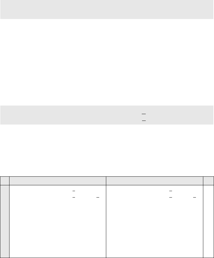
SECTION 7.3 KEY EXPANSION 211
In each round, the calculation of the last three words are very simple. For the calculation of
the first word we need to first calculate the value of temporary word (t). For example, the first t
(for round 1) is calculated as
Example 7.7
Each round key in AES depends on the previous round key. The dependency, however, is nonlin-
ear because of SubWord transformation. The addition of the round constants also guarantees that
each round key will be different from the previous one.
Example 7.8
The two sets of round keys can be created from two cipher keys that are different only in one bit.
As Table 7.6 shows, there are significant differences between the two correspond-
ing round keys (R. means round and B. D. means bit difference).
Example 7.9
The concept of weak keys, as we discussed for DES in Chapter 6, does not apply to AES. Assume
that all bits in the cipher key are 0s. The following shows the words for some rounds:
RotWord (13AA5487) = AA548713 → SubWord (AA548713) = AC20177D
t = AC20177D ⊕ RCon
1
= AC20 17 7D ⊕ 01000000
16
= AD20177D
Cipher Key 1: 12 45 A2 A1 23 31 A4 A3 B2 CC AA 34 C2 BB 77 23
Cipher Key 2: 12 45 A2 A1 23 31 A4 A3 B2 CC AB
34 C2 BB 77 23
Table 7.6 Comparing two sets of round keys
R. Round keys for set 1 Round keys for set 2 B. D.
—
1
2
3
4
5
6
7
8
9
10
1245A2A1 2331A4A3 B2CCAA
34 C2BB7723
F9B08484 DA812027 684D8A
13 AAF6FD30
B9E48028 6365A00F 0B282A1C A1DED72C
A0EAF11A C38F5115 C8A77B09 6979AC25
1E7BCEE3 DDF49FF6 1553E4FF 7C2A48DA
EB2999F3 36DD0605 238EE2FA 5FA4AA20
82852E3C B4582839 97D6CAC3 C87260E3
82553FD4 360D17ED A1DBDD2E 69A9BDCD
D12F822D E72295C0 46F948EE 2F50F523
99C9A438 7EEB31F8 38127916 17428C35
83AD32C8 FD460330 C5547A26 D216F613
1245A2A1 2331A4A3 B2CCAB
34 C2BB7723
F9B08484 DA812027 684D8B
13 AAF6FC30
B9008028 6381A00F 0BCC2B1C A13AD72C
3D0EF11A 5E8F5115 55437A09 F479AD25
839BCEA5 DD149FB0 8857E5B9 7C2E489C
A2C910B5 7FDD8F05 F78A6ABC 8BA42220
CB5AA788 B487288D 430D4231 C8A96011
588A2560 EC0D0DED AF004FDC 67A92FCD
0B9F98E5 E7929508 4892DAD4 2F3BF519
F2794CF0 15EBD9F8 5D79032C 7242F635
E83BDAB0 FDD00348 A0A90064 D2EBF651
01
02
17
30
31
34
56
50
44
51
52

212 CHAPTER 7 ADVANCED ENCRYPTION STANDARD (AES)
The words in the pre-round and the first round are all the same. In the second round, the first
word matches with the third; the second word matches with the fourth. However, after the second
round the pattern disappears; every word is different.
Key Expansion in AES-192 and AES-256
Key-expansion algorithms in the AES-192 and AES-256 versions are very similar to
the key expansion algorithm in AES-128, with the following differences:
1. In AES-192, the words are generated in groups of six instead of four.
a. The cipher key creates the first six words (w
0
to w
5
).
b. If i mod 6 ≠ 0, w
i
← w
i−1
+ w
i−6
; otherwise, w
i
← t + w
i−6
.
2. In AES-256, the words are generated in groups of eight instead of four.
a. The cipher key creates the first eight words (w
0
to w
7
).
b. If i mod 8 ≠ 0, w
i
← w
i−1
+ w
i−8
; otherwise, w
i
← t + w
i−8
.
c. If i mod 4 = 0, but i mod 8 ≠ 0, then w
i
= SubWord (w
i−1
) + w
i−8
.
Key-Expansion Analysis
The key-expansion mechanism in AES has been designed to provide several features
that thwart the cryptanalyst.
1. Even if Eve knows only part of the cipher key or the values of the words in some
round keys, she still needs to find the rest of the cipher key before she can find all
round keys. This is because of the nonlinearity produced by SubWord transforma-
tion in the key-expansion process.
2. Two different cipher keys, no matter how similar to each other, produce two expan-
sions that differ in at least a few rounds.
3. Each bit of the cipher key is diffused into several rounds. For example, changing a
single bit in the cipher key, will change some bits in several rounds.
4. The use of the constants, the RCons, removes any symmetry that may have been
created by the other transformations.
5. There are no serious weak keys in AES, unlike in DES.
6. The key-expansion process can be easily implemented on all platforms.
7. The key-expansion routine can be implemented without storing a single table; all
calculations can be done using the GF(2
8
) and FG(2) fields.
Pre-round:
Round 01:
Round 02:
Round 03:
...
Round 10:
00000000
62636363
9B9898C9
90973450
...
B4EF5BCB
00000000
62636363
F9FBFBAA
696CCFFA
...
3E92E211
00000000
62636363
9B9898C9
F2F45733
...
23E951CF
00000000
62636363
F9FBFBAA
0B0FAC99
...
6F8F188E

SECTION 7.4 CIPHERS 213
7.4 CIPHERS
Now let us see how AES uses four types of transformations for encryption and decryp-
tion. In the standard, the encryption algorithm is referred to as the cipher and the
decryption algorithm as the inverse cipher.
As we mentioned before, AES is a non-Feistel cipher, which means that each trans-
formation or group of transformations must be invertible. In addition, the cipher and
the inverse cipher must use these operations in such a way that cancel each other. The
round keys must also be used in the reverse order. Two different designs are given to be
used for different implementation. We discuss both designs for AES-128; the designs
for other versions are the same.
Original Design
In the original design, the order of transformations in each round is not the same in the
cipher and reverse cipher. Figure 7.17 shows this version.
First, the order of SubBytes and ShiftRows is changed in the reverse cipher.
Second, the order of MixColumns and AddRoundKey is changed in the reverse
cipher. This difference in ordering is needed to make each transformation in the
Figure 7.17 Cipher and inverse cipher of the original design
Round 1
Round 1
Round 9
Plaintext
Ciphertext
Key Expansion
Ke
y
Expansion
W
0
–W
3
W
0
–W
3
Plaintext
Round 9
Round 10
Round 10
AddRoundKey
AddRoundKey
AddRoundKey
SubBytes
InvSubBytes
ShiftRows
InvShiftRows
AddRoundKey
AddRoundKey
SubBytes
ShiftRows
MixColumns
InvMixColumns
AddRoundKey
AddRoundKey
SubBytes
InvSubBytes
ShiftRows
InvShiftRows
AddRoundKey
InvMixColumns
InvSubBytes
InvShiftRows
MixColumns
Inverses
W
4
–W
7
W
4
–W
7
W
40
–W
43
W
40
–W
43
W
36
–W
39
W
36
–W
39
Cipher key Cipher key

214 CHAPTER 7 ADVANCED ENCRYPTION STANDARD (AES)
cipher aligned with its inverse in the reverse cipher. Consequently, the decryption
algorithm as a whole is the inverse of the encryption algorithm. We have shown only
three rounds, but the rest is the same. Note that the round keys are used in the reverse
order. Note that the encryption and decryption algorithms in the original design are
not similar.
Algorithm
The code for the AES-128 version of this design is shown in Algorithm 7.6. The code
for the inverse cipher is left as an exercise.
Alternative Design
For those applications that prefer similar algorithms for encryption and decryption, a
different inverse cipher was developed. In this version, the transformations in the
reverse cipher are rearranged to make the order of transformations the same in the
cipher and reverse cipher. In this design, invertibility is provided for a pair of transfor-
mations, not for each single transformation.
SubBytes/ShiftRows Pairs
SubBytes change the contents of each byte without changing the order of the bytes in
the state; ShiftRows change the order of the bytes in the state without changing the con-
tents of the bytes. This implies that we can change the order of these two transforma-
tions in the inverse cipher without affecting the invertibility of the whole algorithm.
Figure 7.18 shows the idea. Note that the combination of two transformations in the
cipher and inverse cipher are the inverses of each other.
Algorithm 7.6
Pseudocode for cipher in the original design
Cipher (InBlock [16], OutBlock[16], w[0
… 43])
{
BlockToState (InBlock, S)
S
← AddRoundKey (S, w[0…3])
for (round = 1 to 10)
{
S ← SubBytes (S)
S
← ShiftRows (S)
if (round
≠ 10) S ← MixColumns (S)
S
← AddRoundKey (S, w[4 × round, 4 × round + 3])
}
StateToBlock (S, OutBlock);
}

SECTION 7.4 CIPHERS 215
MixColumns/AddRoundKey Pair
Here the two involved transformations are of different nature. However, the pairs can
become inverses of each other if we multiply the key matrix by the inverse of the con-
stant matrix used in MixColumns transformation. We call the new transformation
InvAddRoundKey. Figure 7.19 shows the new configuration.
It can be proved that the two combinations are now inverses of each other. In the
cipher we call the input state to the combination S and the output state T. In the reverse
cipher the input state to the combination is T. The following shows that the output state
is also S. Note that the MixColumns transformation is actually multiplication of the
C matrix (constant matrix by the state).
Now we can show the cipher and inverse cipher for the alternate design. Note that
we still need to use two AddRoundKey transformations in the decryption. In other
words, we have nine InvAddRoundKey and two AddRoundKey transformations as
shown in Figure 7.20.
Changing Key-Expansion Algorithm
Instead of using InvRoundKey transformation in the reverse cipher, the key-expansion
algorithm can be changed to create a different set of round keys for the inverse cipher.
Figure 7.18 Invertibility of SubBytes and ShiftRows combinations
Figure 7.19 Invertibility of MixColumns and AddRoundKey combinations
Cipher: T = CS ⊕ K
Inverse Cipher: C
−1
T ⊕ C
−1
K = C
−1
(CS ⊕ K) ⊕ C
−1
K = C
−1
CS ⊕ C
−1
K ⊕ C
−1
K = S
Inverse
ShiftRows
SubBytes
InvSubBytes
InvShiftRows
Round key
Round key
Inverse
AddRoundKey
MixColumns
InvMixColumns
InvAddRoundKey

216 CHAPTER 7 ADVANCED ENCRYPTION STANDARD (AES)
However, note that the round key for the pre-round operation and the last round should
not be changed. The round keys for rounds 1 to 9 need to be multiplied by the constant
matrix. This algorithm is left as an exercise.
7.5 EXAMPLES
In this section, some examples of encryption/decryption and key generation are given
to emphasize some points discussed in the two previous sections.
Example 7.10
The following shows the ciphertext block created from a plaintext block using a randomly
selected cipher key.
Table 7.7 shows the values of state matrices and round keys for this example.
Figure 7.20 Cipher and reverse cipher in alternate design
Plaintext: 00 04 12 14 12 04 12 00 0C 00 13 11 08 23 19 19
Cipher Key: 24 75 A2 B3 34 75 56 88 31 E2 12 00 13 AA 54 87
Ciphertext: BC 02 8B D3 E0 E3 B1 95 55 0D 6D FB E6 F1 82 41
Round 1
Round 1
Round 9
Plaintext
Ciphertext
Key Expansion
Ke
y
Expansion
W
0
–W
3
W
0
–W
3
Plaintext
Round 9
Round 10
Round 10
AddRoundKey
AddRoundKey
AddRoundKey
SubBytes
InvShiftRows
ShiftRows
InvSubBytes
AddRoundKey
InvAddRoundKey
SubBytes
ShiftRows
MixColumns
InvMixColumns
AddRoundKey
AddRoundKey
SubBytes
InvSubBytes
ShiftRows
InvShiftRows
InvAddRoundKey
InvMixColumns
InvSubBytes
InvShiftRows
MixColumns
Inverses
W
4
–W
7
W
4
–W
7
W
40
–W
43
W
40
–W
43
W
36
–W
39
W
36
–W
39
Cipher key Cipher key

SECTION 7.5 EXAMPLES 217
Table 7.7 Example of encryption
Round Input State Output State Round Key
Pre-round 00 12 0C 08
04 04 00 23
12 12 13 19
14 00 11 19
24 26 3D 1B
71 71 E2 89
B0 44 01 4D
A7 88 11 9E
24 34 31 13
75 75 E2 AA
A2 56 12 54
B3 88 00 87
1 24 26 3D 1B
71 71 E2 89
B0 44 01 4D
A7 88 11 9E
6C 44 13 BD
B1 9E 46 35
C5 B5 F3 02
5D 87 FC 8C
89 BD 8C 9F
55 20 C2 68
B5 E3 F1 A5
CE 46 46 C1
2 6C 44 13 BD
B1 9E 46 35
C5 B5 F3 02
5D 87 FC 8C
1A 90 15 B2
66 09 1D FC
20 55 5A B2
2B CB 8C 3C
CE 73 FF 60
53 73 B1 D9
CD 2E DF 7A
15 53 15 D4
3 1A 90 15 B2
66 09 1D FC
20 55 5A B2
2B CB 8C 3C
F6 7D A2 B0
1B 61 B4 B8
67 09 C9 45
4A 5C 51 09
FF 8C 73 13
89 FA 4B 92
85 AB 74 0E
C5 96 83 57
4 F6 7D A2 B0
1B 61 B4 B8
67 09 C9 45
4A 5C 51 09
CA E5 48 BB
D8 42 AF 71
D1 BA 98 2D
4E 60 9E DF
B8 34 47 54
22 D8 93 01
DE 75 01 0F
B8 2E AD FA
5 CA E5 48 BB
D8 42 AF 71
D1 BA 98 2D
4E 60 9E DF
90 35 13 60
2C FB 82 3A
9E FC 61 ED
49 39 CB 47
D4 E0 A7 F3
54 8C 1F 1E
F3 86 87 88
98 B6 1B E1
6 90 35 13 60
2C FB 82 3A
9E FC 61 ED
49 39 CB 47
18 0A B9 B5
64 68 6A FB
5A EF D7 79
8E B2 10 4D
86 66 C1 32
90 1C 03 1D
0B 8D 0A 82
95 23 38 D9
7 18 0A B9 B5
64 68 6A FB
5A EF D7 79
8E B2 10 4D
01 63 F1 96
55 24 3A 62
F4 8A DE 4D
CC BA 88 03
62 04 C5 F7
83 9F 9C 81
3E B3 B9 3B
B6 95 AD 74
8 01 63 F1 96
55 24 3A 62
F4 8A DE 4D
CC BA 88 03
2A 34 D8 46
2D 6B A2 D6
51 64 CF 5A
87 A8 F8 28
EE EA 2F D8
61 FE 62 E3
AC 1F A6 9D
DE 4B E6 92

218 CHAPTER 7 ADVANCED ENCRYPTION STANDARD (AES)
Example 7.11
Figure 7.21 shows the state entries in one round, round 7, in Example 7.10.
Example 7.12
One may be curious to see the result of encryption when the plaintext is made of all 0s. Using the
cipher key in Example 7.10 yields the ciphertext.
Example 7.13
Let us check the avalanche effect that we discussed in Chapter 6. Let us change only one bit in
the plaintext and compare the results. We changed only one bit in the last byte. The result clearly
shows the effect of diffusion and confusion. Changing a single bit in the plaintext has affected
many bits in the ciphertext.
9 2A 34 D8 46
2D 6B A2 D6
51 64 CF 5A
87 A8 F8 28
0A D9 F1 3C
95 63 9F 35
2A 80 29 00
16 76 09 77
E4 0E 21 F9
3F C1 A3 40
E3 FC 5A C7
BF F4 12 80
10 0A D9 F1 3C
95 63 9F 35
2A 80 29 00
16 76 09 77
BC E0 55 E6
02 E3 0D F1
8B B1 6D 82
D3 95 F8 41
DB D5 F4 0D
F9 38 9B DB
2E D2 88 4F
26 D2 C0 40
Figure 7.21 State in a single round
Plaintext: 00 00 00 00 00 00 00 00 00 00 00 00 00 00 00 00
Cipher Key: 24 75 A2 B3 34 75 56 88 31 E2 12 00 13 AA 54 87
Ciphertext: 63 2C D4 5E 5D 56 ED B5 62 04 01 A0 AA 9C 2D 8D
Plaintext 1: 00 00 00 00 00 00 00 00 00 00 00 00 00 00 00 00
Plaintext 2: 00 00 00 00 00 00 00 00 00 00 00 00 00 00 00 01
Ciphertext 1: 63 2C D4 5E 5D 56 ED B5 62 04 01 A0 AA 9C 2D 8D
Ciphertext 2: 26 F3 9B BC A1 9C 0F B7 C7 2E 7E 30 63 92 73 13
Table 7.7 Example of encryption (continued)
Round Input State Output State Round Key
Input State After SubBytes After ShiftRows After MixColumns Output State
18
64
5A
68
EF
6A
D7
0A B9
FB
79
8E B2 10 D4
B5
7C
36
1D
80
E3
AA
BF
FB A1
FC
7E
7B 4B F4 C4
90 C4
4C
FD
95
7B
C0
69
DE F7
35
C7
59 E3 1E BA
9E 2A
2D
51
6B
64
A2
CF
34 D8
D6
5A
87 A8 F8 28
46 01
55
F4
24
8A
3A
DE
63 F1
62
4D
CC BA 88 03
96

SECTION 7.6 ANALYSIS OF AES 219
Example 7.14
The following shows the effect of using a cipher key in which all bits are 0s.
7.6 ANALYSIS OF AES
Following is a brief review of the three characteristics of AES.
Security
AES was designed after DES. Most of the known attacks on DES were already tested
on AES; none of them has broken the security of AES so far.
Brute-Force Attack
AES is definitely more secure than DES due to the larger-size key (128, 192, and
256 bits). Let us compare DES with 56-bit cipher key and AES with 128-bit cipher key.
For DES we need 2
56
(ignoring the key complement issue) tests to find the key; for AES
we need 2
128
tests to find the key. This means that if we can break DES in t seconds, we
need (2
72
× t) seconds to break AES. This would be almost impossible. In addition,
AES provides two other versions with longer cipher keys. The lack of weak keys is
another advantage of AES over DES.
Statistical Attacks
The strong diffusion and confusion provided by the combination of the SubBytes,
ShiftRows, and MixColumns transformations removes any frequency pattern in the
plaintext. Numerous tests have failed to do statistical analysis of the ciphertext.
Differential and Linear Attacks
AES was designed after DES. Differential and linear cryptanalysis attacks were no
doubt taken into consideration. There are no differential and linear attacks on AES
as yet.
Implementation
AES can be implemented in software, hardware, and firmware. The implementation
can use table lookup process or routines that use a well-defined algebraic structure. The
transformation can be either byte-oriented or word-oriented. In the byte-oriented ver-
sion, the whole algorithm can use an 8-bit processor; in the word-oriented version,
it can use a 32-bit processor. In either case, the design of constants makes processing
very fast.
Plaintext: 00 04 12 14 12 04 12 00 0c 00 13 11 08 23 19 19
Cipher Key: 00 00 00 00 00 00 00 00 00 00 00 00 00 00 00 00
Ciphertext: 5A 6F 4B 67 57 B7 A5 D2 C4 30 91 ED 64 9A 42 72

220 CHAPTER 7 ADVANCED ENCRYPTION STANDARD (AES)
Simplicity and Cost
The algorithms used in AES are so simple that they can be easily implemented using
cheap processors and a minimum amount of memory.
7.7 RECOMMENDED READING
The following books and websites give more details about subjects discussed in this
chapter. We recommend the following books and sites. The items enclosed in brackets
refer to the reference list at the end of the book.
Books
[Sta06], [Sti06], [Rhe03], [Sal03], [Mao04], and [TW06] discuss AES.
WebSites
The following websites give more information about topics discussed in this chapter.
7.8 KEY TERMS
7.9 SUMMARY
❏ The Advanced Encryption Standard (AES) is a symmetric-key block cipher pub-
lished by NIST as FIPS 197. AES is based on the Rijndael algorithm.
csrc.nist.gov/publications/fips/fips197/fips-197.pdf
http://www.quadibloc.com/crypto/co040401.htm
http://www.ietf.org/rfc/rfc3394.txt
AddRoundKey key expansion
Advanced Encryption Standard (AES) MixColumns
bit
block
National Institute of Standards and
Technology (NIST)
byte Rijndael
cipher RotWord
InvAddRoundKey ShiftRows
inverse cipher state
InvMixColumns SubBytes
InvShiftRows SubWord
InvSubBytes word

SECTION 7.10 PRACTICE SET 221
❏ AES is a non-Feistel cipher that encrypts and decrypts a data block of 128 bits. It
uses 10, 12, or 14 number of rounds. The key size, which can be 128, 192, or 256
bits depends on the number of rounds.
❏ AES is byte-oriented. The 128-bit plaintext or ciphertext is considered as sixteen 8-bit
bytes. To be able to perform some mathematical transformations on bytes, AES has
defined the concept of a state. A state is a 4 × 4 matrix in which each entry is a byte.
❏ To provide security, AES uses four types of transformations: substitution, permuta-
tion, mixing, and key-adding. Each round of AES, except the last, uses the four
transformations. The last round uses only three of the four transformations.
❏ Substitution is defined by either a table lookup process or mathematical calculation
in the GF(2
8
) field. AES uses two invertible transformations, SubBytes and Inv-
SubBytes, which are inverses of each other.
❏ The second transformation in a round is shifting, which permutes the bytes. In the
encryption, the transformation is called ShiftRows. In the decryption, the transfor-
mation is called InvShiftRows. The ShiftRows and InvShiftRows transformations
are inverses of each other.
❏ The mixing transformation changes the contents of each byte by taking four bytes
at a time and combining them to recreate four new bytes. AES defines two trans-
formations, MixColumns and InvMixColumns, to be used in the encryption and
decryption. MixColumns multiplies the state matrix by a constant square matrix;
the InvMixColumns does the same using the inverse constant matrix. The
MixColumns and InvMixColumns transformations are inverses of each other.
❏ The transformation that performs whitening is called AddRoundKey. The previous
state is added (matrix addition) with the round matrix key to create the new state.
Addition of individual elements in the two matrices is done in GF(2
8
), which means
that 8-bit words are XORed. The AddRoundKey transformation is the inverse of itself.
❏ In the first configuration (10 rounds with 128-bit keys), the key generator creates
eleven 128-bit round keys out of the 128-bit cipher key. AES uses the concept of a
word for key generation. A word is made of four bytes. The round keys are gener-
ated word by word. AES numbers the words from w
0
to w
43
. The process is
referred to as key expansion.
❏ AES cipher uses two algorithms for decryption. In the original design, the order
of transformations in each round is not the same in the encryption and decryption.
In the alternative design, the transformations in the decryption algorithms are
rearranged to make ordering the same in encryption and decryption. In the second
version, the invertibility is provided for a pair of transformations.
7.10 PRACTICE SET
Review Questions
1. List the criteria defined by NIST for AES.
2. List the parameters (block size, key size, and the number of rounds) for the three
AES versions.
222 CHAPTER 7 ADVANCED ENCRYPTION STANDARD (AES)
3. How many transformations are there in each version of AES? How many round
keys are needed for each version?
4. Compare DES and AES. Which one is bit-oriented? Which one is byte-oriented?
5. Define a state in AES. How many states are there in each version of AES?
6. Which of the four transformations defined for AES change the contents of bytes?
Which one does not change the contents of the bytes?
7. Compare the substitution in DES and AES. Why do we have only one substitution
table (S-box) in AES, but several in DES?
8. Compare the permutations in DES and AES. Why do we need expansion and com-
pression permutations in DES, but not in AES?
9. Compare the round keys in DES and AES. In which cipher is the size of the round
key the same as the size of the block?
10. Why do you think the mixing transformation (MixColumns) is not needed in DES,
but is needed in AES?
Exercises
11. In a cipher, S-boxes can be either static or dynamic. The parameters in a static S-box
do not depend on the key.
a. State some advantages and some disadvantages of static and dynamic S-boxes.
b. Are the S-boxes (substitution tables) in AES static or dynamic?
12. AES has a larger block size than DES (128 versus 64). Is this an advantage or dis-
advantage? Explain.
13. AES defines different implementations with three different numbers of rounds
(10, 12, and 14); DES defines only implementation with 16 rounds. What are
the advantages and disadvantages of AES over DES with respect to this
difference?
14. AES defines three different cipher-key sizes (128, 192, and 256); DES defines only
one cipher-key size (56). What are the advantages and disadvantages of AES over
DES with respect to this difference?
15. In AES, the size of the block is the same as the size of the round key (128 bits); in
DES, the size of the block is 64 bits, but the size of the round key is only 48 bits.
What are the advantages and disadvantages of AES over DES with respect to this
difference?
16. Prove that the ShiftRows and InvShiftRows transformations are permutations by
doing the following:
a. Show the permutation table for ShiftRows. The table needs to have 128 entries,
but since the contents of a byte do not change, the table can have only 16 entries
with the assumption that each entry represents a byte.
b. Repeat Part a for InvShiftRows transformation.
c. Using the results of Parts a and b, prove that the ShiftRows and InvShiftRows
transformations are inverses of each other.

SECTION 7.10 PRACTICE SET 223
17. Using the same cipher key, apply each of the following transformations on two
plaintexts that differ only in the first bit. Find the number of bits changed after each
transformation. Each transformation is applied independently.
a. SubBytes
b. ShiftRows
c. MixColumns
d. AddRoundKey (with the same round keys of your choice)
18. To see the nonlinearity of the SubBytes transformation, show that if a and b are
two bytes, we have
Use a = 0x57 and b = 0xA2 as an example.
19. Give a general formula to calculate the number of each kind of transformation
(SubBytes, ShiftRows, MixColumns, and AddRoundKey) and the number of total
transformations for each version of AES. The formula should be parametrized on
the number of rounds.
20. Redraw Figure 7.16 for AES-192 and AES-256.
21. Create two new tables that show RCons constants for the AES-192 and AES-256
implementations (see Table 7.4).
22. In AES-128, the round key used in the pre-round operation is the same as the
cipher key. Is this the case for AES-192? Is this the case for AES-256?
23. In Figure 7.8, multiply the X and X
−1
matrices to prove that they are inverses of
each other.
24. Using Figure 7.12, rewrite the square matrices C and C
−1
using polynomials with
coefficients in GF(2). Multiply the two matrices and prove that they are inverse of
each other.
25. Prove that the code in Algorithm 7.1 (SubBytes transformation) matches the pro-
cess shown in Figure 7.8.
26. Using Algorithm 7.1 (SubBytes transformation), do the following:
a. Write the code for a routine that calculates the inverse of a byte in GF(2
8
).
b. Write the code for ByteToMatrix.
c. Write the code for MatrixToByte.
27. Write an algorithm for the InvSubBytes transformation.
28. Prove that the code in Algorithm 7.2 (ShiftRows transformation) matches the pro-
cess shown in Figure 7.9.
29. Using Algorithm 7.2 (ShiftRows transformation), write the code for CopyRow
routine.
30. Write an algorithm for the InvShiftRows transformation.
31. Prove that the code in Algorithm 7.3 (MixColumns transformation) matches with
the process shown in Figure 7.13.
SubBytes (a ⊕ b) ≠ SubBytes (a) ⊕ SubBytes (b)
224 CHAPTER 7 ADVANCED ENCRYPTION STANDARD (AES)
32. Using Algorithm 7.3 (MixColumns transformation), write the code for the Copy-
Column routine.
33. Rewrite Algorithm 7.3 (MixColumns transformation) replacing the operators (.)
with a routine called MultField to calculate the multiplication of two bytes in the
GF(2
8
) field.
34. Write an algorithm for InvMixColumns transformation.
35. Prove that the code in Algorithm 7.4 (AddRoundKey transformation) matches the
process shown in Figure 7.15.
36. In Algorithm 7.5 (Key Expansion),
a. Write the code for the SubWord routine.
b. Write the code for the RotWord routine.
37. Give two new algorithms for key expansion in AES-192 and AES-256 (see Algo-
rithm 7.5).
38. Write the key-expansion algorithm for alternate inverse cipher.
39. Write the algorithm for inverse cipher in the original design.
40. Write the algorithm for the inverse cipher in the alternative design.

225
CHAPTER 8
Encipherment Using
Modern Symmetric-Key Ciphers
Objectives
This chapter has several objectives:
❏ To show how modern standard ciphers, such as DES or AES, can be
used to encipher long messages.
❏ To discuss five modes of operation designed to be used with modern
block ciphers.
❏ To define which mode of operation creates stream ciphers out of the
underlying block ciphers.
❏ To discuss the security issues and the error propagation of different
modes of operation.
❏ To discuss two stream ciphers used for real-time processing of data.
This chapter shows how the concepts discussed in Chapter 5 and two
modern block ciphers discussed in Chapters 6 and 7 can be used to enci-
pher long messages. It also introduces two stream ciphers.
8.1 USE OF MODERN BLOCK CIPHERS
Symmetric-key encipherment can be done using modern block ciphers. The two
modern block ciphers discussed in Chapters 6 and 7, namely DES and AES, are
designed to encipher and decipher a block of text of fixed size. DES encrypts and
decrypts a block of 64 bits; AES encrypts and decrypts a block of 128 bits. In real-
life applications, the text to be enciphered is of variable size and normally much
larger than 64 or 128 bits. Modes of operation have been devised to encipher text of
any size employing either DES or AES. Figure 8.1 shows the five modes of operation
that will be discussed here.

226 CHAPTER 8 ENCIPHERMENT USING MODERN SYMMETRIC-KEY CIPHERS
Electronic Codebook (ECB) Mode
The simplest mode of operation is called the electronic codebook (ECB) mode. The
plaintext is divided into N blocks. The block size is n bits. If the plaintext size is not a
multiple of the block size, the text is padded to make the last block the same size as the
other blocks. The same key is used to encrypt and decrypt each block. Figure 8.2 shows
the encryption and decryption in this mode.
The relation between plaintext and ciphertext block is shown below:
Example 8.1
It can be proved that each plaintext block at Alice’s site is exactly recovered at Bob’s site.
Because encryption and decryption are inverses of each other,
Example 8.2
This mode is called electronic codebook because one can precompile 2
K
codebooks (one for each
key) in which each codebook has 2
n
entries in two columns. Each entry can list the plaintext and
Figure 8.1
Modes of operation
Figure 8.2
Electronic codebook (ECB) mode
Encryption: C
i
=
E
K
(P
i
)
Decryption: P
i
= D
K
(C
i
)
P
i
=
D
K
(C
i
)
=
D
K
(E
K
(P
i
))
=
P
i
Modes of
operation
Output
feedback
Counter
Cipher
feedback
Cipher block
chaining
Electronic
codebook
ECB CBC CFB OFB CTR
Encr
y
ption
E: Encryption
P
i
: Plaintext block i
K: Secret key
D: Decryption
C
i
: Ciphertext block i
K
E
P
1
C
1
K
E
P
2
C
2
K
E
P
N
C
N
n bits
n bits
n bits n bits
n bits n bits
Decr
y
ption
K
D
P
1
C
1
K
D
P
2
C
2
K
D
P
N
C
N
n bits
n bits
n bits n bits
n bits n bits

SECTION 8.1 USE OF MODERN BLOCK CIPHERS 227
the corresponding ciphertext blocks. However, if K and n are large, the codebook would be far
too large to precompile and maintain.
Security Issues
Following are security issues in CBC mode:
1. Patterns at the block level are preserved. For example, equal blocks in the plaintext
become equal blocks in the ciphertext. If Eve finds out that ciphertext blocks 1, 5,
and 10 are the same, she knows that plaintext blocks 1, 5, and 10 are the same. This
is a leak in security. For example, Eve can do an exhaustive search to decrypt only
one of these blocks to find the contents of all of them.
2. The block independency creates opportunities for Eve to exchange some ciphertext
blocks without knowing the key. For example, if she knows that block 8 always
conveys some specific information, she can replace this block with the correspond-
ing block in the previously intercepted message.
Example 8.3
Assume that Eve works in a company a few hours per month (her monthly payment is very
low). She knows that the company uses several blocks of information for each employee in
which the seventh block is the amount of money to be deposited in the employee’s account.
Eve can intercept the ciphertext sent to the bank at the end of the month, replace the block
with the information about her payment with a copy of the block with the information about
the payment of a full-time colleague. Each month Eve can receive more money than she
deserves.
Error Propagation
A single bit error in transmission can create errors in several (normally half of the bits
or all of the bits) in the corresponding block. However, the error does not have any
effect on the other blocks.
Algorithm
Simple algorithms can be written for encryption or decryption. Algorithm 8.1 gives the
pseudocode routine for encryption; the routine for decryption is left as an exercise. E
K
encrypts a single block and can be one of the ciphers discussed in Chapters 6 or 7 (DES
or AES).
Algorithm 8.1 Encryption for ECB mode
ECB_Encryption (K, Plaintext blocks)
{
for (i = 1 to N)
{
C
i
← E
K
(P
i
)
}
return
Ciphertext blocks
}

228 CHAPTER 8 ENCIPHERMENT USING MODERN SYMMETRIC-KEY CIPHERS
Ciphertext Stealing
In ECB mode, padding must be added to the last block if it is not n bits long. Padding is
not always possible. For example, when the ciphertext needs to be stored in the buffer
where the plaintext was previously stored, plaintext and ciphertext must be the same. A
technique called ciphertext stealing (CTS) can make it possible to use ECB mode
without padding. In this technique the last two plaintext blocks, P
N−1
and P
N
, are
encrypted differently and out of order, as shown below, assuming that P
N−1
has n bits
and P
N
has m bits, where m ≤ n.
The head
m
function selects the leftmost m bits; the tail
n−m
function selects the
rightmost n − m bits. The detailed diagram and the procedure of the encryption and
decryption are left as exercises.
Applications
The ECB mode of operation is not recommended for encryption of messages of
more than one block to be transferred through an insecure channel. If the message
is short enough to fit in one block, the security issues and propagation errors are
tolerable.
One area where the independency of the ciphertext block is useful is where records
need to be encrypted before they are stored in a database or decrypted before they are
retrieved. Because the order of encryption and decryption of blocks is not important in
this mode, access to the database can be random if each record is a block or multiple
blocks. A record can be retrieved from the middle, decrypted, and encrypted after mod-
ification without affecting other records.
Another advantage of this mode is that we can use parallel processing if we need to
create, for example, a very huge encrypted database.
Cipher Block Chaining (CBC) Mode
The next evolution in the operation mode is the cipher block chaining (CBC) mode.
In CBC mode, each plaintext block is exclusive-ored with the previous ciphertext
block before being encrypted. When a block is enciphered, the block is sent, but a
copy of it is kept in memory to be used in the encryption of the next block. The reader
may wonder about the initial block. There is no ciphertext block before the first block.
In this case, a phony block called the initialization vector (IV) is used.The sender
and receiver agree upon a specific predetermined IV. In other words, an IV is
used instead of the nonexistent C
0
. Figure 8.3 shows CBC mode. At the sender side,
exclusive-oring is done before encryption; at the receiver site, decryption is done
before exclusive-oring.
X
=
E
K
(P
N − 1
)
→
C
N
=
head
m
(
X)
Y
=
P
N
| tail
n−m
(X)
→
C
N − 1
=
E
K
(Y)

SECTION 8.1 USE OF MODERN BLOCK CIPHERS 229
The relation between plaintext and ciphertext blocks is shown below:
Example 8.4
It can be proved that each plaintext block at Alice’s site is recovered exactly at Bob’s site.
Because encryption and decryption are inverses of each other,
Initialization Vector (IV)
The initialization vector (IV) should be known by the sender and the receiver. Although
keeping the vector secret is not necessary, the integrity of the vector plays an important
role in the security of CBC mode; IV should be kept safe from change. If Eve can
change the bit values of the IV, it can change the bit values of the first block.
Several methods have been recommended for using IV. A pseudorandom number
can be selected by the sender and transmitted through a secure channel (using ECB
mode for example). A fixed value can be agreed upon by Alice and Bob as the IV when
the secret key is established. It can be part of the secret key, and so on.
Security Issues
Following are two of the security issues in CBC mode:
1. In CBC mode, equal plaintext blocks belonging to the same message are enci-
phered into different ciphertext blocks. In other words, the patterns at the block
Figure 8.3
Cipher block chaining (CBC) mode
Encryption:
C
0
=
IV
C
i
=
E
K
(P
i
⊕
C
i −1
)
Decryption:
C
0
= IV
P
i
= D
K
(C
i
) ⊕ C
i −1
P
i
= D
K
(C
i
) ⊕ C
i −1
= D
K
(E
K
(P
i
⊕ C
i −1
)) ⊕ C
i −1
= P
i
⊕ C
i −1
⊕ C
i −1
= P
i
Encryption
(IV)
K K K
E
E: Encryption
P
i
: Plaintext block i
K: Secret key
D : Decryption
C
i
: Ciphertext block i
IV: Initial vector (C
0
)
P
1
E
P
2
E
P
N
C
1
C
2
C
N
C
N−1
n bits
n bits n bits n bits
n bits n bits
Decryption
(IV)
K K K
D
P
1
D
P
2
D
P
N
C
1
C
2
C
N
C
N−1
n bits
n bits n bits n bits
n bits n bits

230 CHAPTER 8 ENCIPHERMENT USING MODERN SYMMETRIC-KEY CIPHERS
levels are not preserved. However, if two messages are equal, their encipherment is
the same if they use the same IV. As a matter of fact, if the first M blocks in two
different messages are equal, they are enciphered into equal blocks unless different
IVs are used. For this reason, some people recommend the use of a timestamp
as an IV.
2. Eve can add some ciphertext blocks to the end of the ciphertext stream.
Error Propagation
In CBC mode, a single bit error in ciphertext block C
j
during transmission may create
error in most bits in plaintext block P
j
during decryption. However, this single error
toggles only one bit in plaintext block P
j+1
(the bit in the same location). The proof of
this fact is left as an exercise. Plaintext blocks P
j+2
to
P
N
are not affected by this single
bit error. A single bit error in ciphertext is self-recovered.
Algorithm
Algorithm 8.2 gives the pseudocode for encryption. The algorithm calls the encrypt
routine that encrypts a single block (DES or AES, for example). The decryption algo-
rithm is left as an exercise.
Ciphertext Stealing
The ciphertext stealing technique described for ECB mode can also be applied to CBC
mode, as shown below
The head function is the same as described in ECB mode; the pad function
inserts 0’s.
Applications
The CBC mode of operation can be used to encipher messages. However, because of
chaining mechanism, parallel processing is not possible. CBC mode is not used to
Algorithm 8.2
Encryption algorithm for CBC mode
CBC_Encryption (IV, K, Plaintext blocks)
{
C
0
←
IV
for (i = 1 to N)
{
Temp
←
P
i
⊕
C
i
−
1
C
i
← E
K
(Temp)
}
return
Ciphertext blocks
}
U
=
P
N−1
⊕
C
N−2
→
X
=
E
K
(U)
→
C
N
=
head
m
(
X).
V = P
N
| pad
n−m
(0) → Y =
X ⊕ V → C
N−1
= E
K
(Y)


232 CHAPTER 8 ENCIPHERMENT USING MODERN SYMMETRIC-KEY CIPHERS
The relation between plaintext and ciphertext blocks is shown below:
where the ShiftLeft
r
routine shifts the contents of its argument r bits to the left (the
leftmost r bits are dropped). The operator | shows the concatenation. The SelectLeft
r
routine selects only the leftmost r bits from the argument. It can be proven that each
plaintext block at Alice’s site is recovered exactly at Bob’s site, but the proof is left as
an exercise.
One interesting point about this mode is that no padding is required because the
size of the blocks, r, is normally chosen to fit the data unit to be encrypted (a character,
for example). Another interesting point is that the system does not have to wait until it
has received a large block of data (64 bits or 128 bits) before starting the encryption.
The encrypting process is done for a small block of data (such as a character). These
two advantages come with a disadvantage. CFB is less efficient than CBC or ECB,
because it needs to apply the encryption function of underlying block cipher for each
small block of size r.
CFB as a Stream Cipher
Although CFB is an operation mode for using block ciphers such as DES or AES, the
result is a stream cipher. In fact, it is a nonsynchronous stream cipher in which the key
stream is dependent on the ciphertext. Figure 8.5 shows the point of the encryption and
decryption where the key generator is conspicuous.
In CFB mode, encipherment and decipherment use the encryption function of the
underlying block cipher.
Encryption: C
i
= P
i
⊕ SelectLeft
r
{E
K
[ShiftLeft
r
(S
i
−
1
) | C
i −1
)]}
Decryption: P
i
= C
i
⊕ SelectLeft
r
{E
K
[ShiftLeft
r
(S
i
−
1
) | C
i −1
)]}
Figure 8.5 Cipher feedback (CFB) mode as a stream cipher
Encr
y
ption
Key generator
C
i−1
Insecure channel
C
i
P
i
k
i
(r bits)
r bits
r bits
E
n bits
K
T
i
S
i
Decr
y
ption
Key generator
C
i−1
P
i
C
i
k
i
(r bits)
r bits
r bits
E
n bits
K
T
i
S
i

SECTION 8.1 USE OF MODERN BLOCK CIPHERS 233
Figure 8.5 shows that the underlying cipher (DES or AES), the cipher key (K), and
the previous cipher block (C
i
) are used only to create the key streams (k
1
, k
2
, …, k
N
).
Algorithm
Algorithm 8.3 gives the routine for encryption. The algorithm calls several other rou-
tines whose details are left as exercises. Note that we have written the algorithm in such
a way to show the stream nature of the mode (real-time situation). The algorithm runs
as long as there are plaintext blocks to be encrypted.
Security Issues
There are three primary security issues in CFB mode:
1. Just like CBC, the patterns at the block level are not preserved.
2. More than one message can be encrypted with the same key, but the value of the IV
should be changed for each message. This means that Alice needs to use a different
IV each time she sends a message.
3. Eve can add some ciphertext block to the end of the ciphertext stream.
Error Propagation
In CFB, a single bit error in ciphertext block C
j
during transmission creates a single
bit error (at the same position) in plaintext block P
j
. However, most of the bits in the
Algorithm 8.3
Encryption algorithm for CFB
CFB_Encryption (IV, K, r)
{
i
← 1
while (more blocks to encrypt)
{
input (P
i
)
if (i
= 1)
S
← IV
else
{
Temp
← shiftLeft
r
(S)
S
← concatenate (Temp, C
i–1
)
}
T
← E
K
(S)
k
i
← selectLeft
r
(T)
C
i
← P
i
⊕ k
i
output (C
i
)
i
← i + 1
}
}


SECTION 8.1 USE OF MODERN BLOCK CIPHERS 235
stream cipher is synchronous as discussed in Chapter 5. Figure 8.7 shows the encryp-
tion and decryption in which the key generator is conspicuous.
Algorithm
Algorithm 8.4 gives the routine for encryption. The algorithm calls several other rou-
tines whose details are left as exercises. Note that we have written the algorithm in such
Figure 8.7 Output feedback (OFB) mode as a stream cipher
Algorithm 8.4 Encryption algorithm for OFB
OFB_Encryption (IV, K, r)
{
i
← 1
while (more blocks to encrypt)
{
input (P
i
)
if (i
= 1) S ← IV
else
{
Temp ← shiftLeft
r
(S)
S
← concatenate (Temp, k
i−1
)
}
T
← E
K
(S)
k
i
← selectLeft
r
(T)
C
i
← P
i
⊕ k
i
output (C
i
)
i
← i + 1
}
}
Encryption
Key generator
Insecure channel
C
i
P
i
r bits
r bits
K
T
i
S
i
E
n bits
Decryption
Key generator
P
i
C
i
k
i
r bits
r bits
K
T
i
S
i
E
n bits
(r bits)
k
i
(r bits)

236 CHAPTER 8 ENCIPHERMENT USING MODERN SYMMETRIC-KEY CIPHERS
a way to show the stream nature of the mode (real-time situation). The algorithm runs
as long as there are plaintext blocks to be encrypted.
Security Issues
Following are two of the security issues in OFB mode:
1. Just like the CFB mode, patterns at the block level are not preserved.
2. Any change in the ciphertext affects the plaintext encrypted at the receiver side.
Error Propagation
A single error in the ciphertext affects only the corresponding bit in the plaintext.
Special Case
If the blocks in the text and the underlying cipher are of the same size (n = r), the
encryption/decryption becomes simpler, but we leave the discovery of the diagram and
the algorithm as an exercise.
Counter (CTR) Mode
In the counter (CTR) mode, there is no feedback. The pseudorandomness in the key
stream is achieved using a counter. An n-bit counter is initialized to a pre-determined
value (IV) and incremented based on a predefined rule (mod 2
n
). To provide a better
randomness, the increment value can depend on the block number to be incremented.
The plaintext and ciphertext block have the same block size as the underlying cipher
(e.g., DEA or AES). Plaintext blocks of size n are encrypted to create ciphertext blocks
of size n. Figure 8.8 shows the counter mode.
Figure 8.8
Encryption in counter (CTR) mode
E : Encryption
P
i
: Plaintext block i
K : Secret key
IV: Initialization vector
C
i
: Ciphertext block i
k
i
: Encryption key i
The counter is incremented for each block.
Encr
y
ption
P
N
C
N
P
2
C
2
C
1
P
1
E
n bits
n bits
n bits n bits
K
k
1
n bits
k
2
n bits
k
N
IV
E
n bits
n bits
n bits
K
Counter
E
n bits
n bits n bits
K
Counter

SECTION 8.1 USE OF MODERN BLOCK CIPHERS 237
The relation between plaintext and ciphertext blocks is shown below.
CTR uses the encryption function of the underlying block cipher (E
K
) for both
encipherment and decipherment. It is easy to prove that the plaintext block P
i
can be
recovered from the ciphertext C
i
. This is left as an exercise.
We can compare CTR mode to OFB and ECB modes. Like OFB, CTR creates a key
stream that is independent from the previous ciphertext block, but CTR does not use feed-
back. Like ECB, CTR creates n-bit ciphertext blocks that are independent from each other;
they depend only on the value of the counter. On the negative side, this means that CTR
mode, like ECB mode, cannot be used for real-time processing. The encrypting algorithm
needs to wait to get a complete n-bit block of data before encrypting. On the positive side,
CTR mode, like ECB mode can be used to encrypt and decrypt random-access files as long
as the value of the counter can be related to the record number in the file.
CTR as a Stream Cipher
Like CFB and OFB, CTR is actually a stream cipher (different block are exclusive-ored
with different keys). Figure 8.9 shows encryption and decryption of the ith data block.
Algorithm
Algorithm 8.5 gives the routine in pseudocode for encryption; the algorithm for decryp-
tion is left as an exercise. In this algorithm, the increment value is dependent on the
block number. In other words, the counter values are IV, IV + 1, IV + 3, IV + 6, and so
on. It is also assumed that all N plaintext blocks are ready before starting encryption,
but the algorithm can be rewritten to avoid this assumption.
Security Issues
The security issues for the CTR mode are the same as the those for OFB mode.
Error Propagation
A single error in the ciphertext affects only the corresponding bit in the plaintext.
Encryption: C
i
= P
i
⊕ (Counter) Decryption: P
i
= C
i
⊕
(Counter)
Figure 8.9 Counter (CTR) mode as a stream cipher
E
k
i
E
k
i
Encr
y
ption
Insecure channel
Decr
y
ption
C
i
P
i
E
n bits
n bits
n bits n bits
K
k
i
Counter
P
i
C
i
E
n bits
n bits
n bitsn bits
K
k
i
Counter
Key generator Key generator

238 CHAPTER 8 ENCIPHERMENT USING MODERN SYMMETRIC-KEY CIPHERS
Comparison of Different Modes
Table 8.1 briefly compares the five different modes of operation discussed in this chapter.
8.2 USE OF STREAM CIPHERS
Although the five modes of operations enable the use of block ciphers for encipherment
of messages or files in large units (ECB, CBC, and CTR) and small units (CFB and
OFB), sometimes pure stream are needed for enciphering small units of data such as
characters or bits. Stream ciphers are more efficient for real-time processing. Several
stream ciphers have been used in different protocols during the last few decades. We
discuss only two: RC4 and A5/1.
RC4
RC4 is a stream cipher that was designed in 1984 by Ronald Rivest for RSA Data
Security. RC4 is used in many data communication and networking protocols, includ-
ing SSL/TLS (see Chapter 17) and the IEEE802.11 wireless LAN standard.
Algorithm 8.5
Encryption algorithm for CTR
CTR_Encryption (IV, K,
Plaintext blocks)
{
Counter
← IV
for (i = 1 to N )
{
Counter
← (Counter + i − 1) mod 2
N
k
i
← E
K
(Counter)
C
i
← P
i
⊕ k
i
}
return Ciphertext blocks
}
Table 8.1 Summary of operation modes
Operation
Mode
Description
Type of
Result
Data Unit
Size
ECB Each n-bit block is encrypted independently with
the same cipher key.
Block
cipher
n
CBC Same as ECB, but each block is first exclusive-ored
with the previous ciphertext.
Block
cipher
n
CFB Each r-bit block is exclusive-ored with an r-bit key,
which is part of previous cipher text
Stream
cipher
r ≤ n
OFB Same as CFB, but the shift register is updated by the
previous r-bit key.
Stream
cipher
r ≤ n
CTR Same as OFB, but a counter is used instead of a shift
register.
Stream
cipher
n

SECTION 8.2 USE OF STREAM CIPHERS 239
RC4 is a byte-oriented stream cipher in which a byte (8 bits) of a plaintext is
exclusive-ored with a byte of key to produce a byte of a ciphertext. The secret key,
from which the one-byte keys in the key stream are generated, can contain anywhere
from 1 to 256 bytes.
State
RC4 is based on the concept of a state. At each moment, a state of 256 bytes is active,
from which one of the bytes is randomly selected to serve as the key for encryption.
The idea can be shown as an array of bytes:
Note that the indices of the elements range between 0 and 255. The contents of each
element is also a byte (8 bits) that can be interpreted as an integer between 0 to 255.
The Idea
Figure 8.10 shows the whole idea of RC4. The first two boxes are performed only once
(initializing); the permutation for creating stream key is repeated as long as there are
plaintext bytes to encrypt.
S[0] S[1] S[2]
…
S[255]
Figure 8.10 The idea of RC4 stream cipher
State and key initialization
(done only once)
S[0]
0
S[1]
1
S[2]
2
S[255]
255
Mix with key bytes
and permute
K[0]K[1] K[2] K[255]
Initial state permutation
(done only once)
0 1 2 255
Key
Encryption
(first b
y
te)
(8 bits)
C
P
8 bits 8 bits
k
State permutation for
key stream generation
State permutation for
key stream generation
State permutation for
key stream generation
Permute state values Permute state values Permute state values
Encryption
(second b
y
te)
(8 bits)
C
P
8 bits 8 bits
k
Encryption
(last b
y
te)
(8 bits)
C
P
8 bits 8 bits
k

240 CHAPTER 8 ENCIPHERMENT USING MODERN SYMMETRIC-KEY CIPHERS
Initialization Initialization is done in two steps:
1. In the first step, the state is initialized to values 0, 1, …, 255. A key array, K[0], K[1],
…, K[255] is also created. If the secret key has exactly 256 bytes, the bytes are cop-
ied to the K array; otherwise, the bytes are repeated until the K array is filled.
2. In the second step, the initialized state goes through a permutation (swapping the
elements) based on the value of the bytes in K[i]. The key byte is used only in this
step to define which elements are to be swapped. After this step, the state bytes are
completely shuffled.
Key Stream Generation The keys in the key stream, the k’s, are generated, one by
one. First, the state is permuted based on the values of state elements and the values of
two individual variables, i and j. Second, the values of two state elements in positions
i and j are used to define the index of the state element that serves as k. The following
code is repeated for each byte of the plaintext to create a new key element in the key
stream. The variables i and j are initialized to 0 before the first iteration, but the values
are copied from one iteration to the next.
Encryption or Decryption After k has been created, the plaintext byte is encrypted
with k to create the ciphertext byte. Decryption is the reverse process.
Algorithm
Algorithm 8.6 shows the pseudocode routine for RC4.
for (i = 0 to 255)
{
S[i] ← i
K[i] ← Key [i mod KeyLength]
}
j ← 0
for (i = 0 to 255)
{
j ← (j + S[i] + K[i]) mod 256
swap (S[i] , S[j])
}
i ← (i + 1) mod 256
j ← (j + S[i]) mod 256
swap (S [i] , S[j])
k ← S [(S[i] + S[j]) mod 256]

SECTION 8.2 USE OF STREAM CIPHERS 241
Example 8.5
To show the randomness of the stream key, we use a secret key with all bytes set to 0. The key
stream for 20 values of k is (222, 24, 137, 65, 163, 55, 93, 58, 138, 6, 30, 103, 87, 110, 146, 109,
199, 26, 127, 163).
Example 8.6
Repeat Example 8.5, but let the secret key be five bytes of (15, 202, 33, 6, 8). The key stream is
(248, 184, 102, 54, 212, 237, 186, 133, 51, 238, 108, 106, 103, 214, 39, 242, 30, 34, 144, 49).
Again the randomness in the key stream is obvious.
Algorithm 8.6 Encryption algorithm for RC4
RC4_Encryption (K)
{
// Creation of initial state and key bytes
for (i = 0 to 255)
{
S[i]
← i
K[i]
← Key [i mod KeyLength]
}
// Permuting state bytes based on values of key bytes
j ← 0
for (i = 0 to 255)
{
j
← (j + S[i] + K[i]) mod 256
swap (S[i]
, S[j])
}
// Continuously permuting state bytes, generating keys, and encrypting
i
← 0
j
← 0
while (more byte to encrypt)
{
i
← (i + 1) mod 256
j
← (j + S[i]) mod 256
swap (S [i]
, S[j])
k
← S [(S[i] + S[j]) mod 256]
// Key is ready, encrypt
input P
C ← P ⊕ k
output C
}
}

242 CHAPTER 8 ENCIPHERMENT USING MODERN SYMMETRIC-KEY CIPHERS
Security Issues
It is believed that the cipher is secure if the key size is at least 128 bits (16 bytes). There
are some reported attacks for smaller key sizes (less than 5 bytes), but the protocols that
use RC4 today all use key sizes that make RC4 secure. However, like many other
ciphers, it is recommended the different keys be used for different sessions. This pre-
vents Eve from using differential cryptanalysis on the cipher.
A5/1
In this section we introduce a stream cipher that uses LFSRs (see Chapter 5) to create a bit
stream: A5/1. A5/1 (a member of the A5 family of ciphers) is used in the Global System for
Mobile Communication (GSM), a network for mobile telephone communication. Phone
communication in GSM is done as a sequence of 228-bit frames in which each frame lasts
4.6 milliseconds. A5/1 creates a bit stream out of a 64-bit key. The bit streams are collected
in a 228-bit buffer to be exclusive-ored with a 228-bit frame, as shown in Figure 8.11.
Key Generator
A5/1 uses three LFSRs with 19, 22, and 23 bits. The LFSRs, the characteristic polyno-
mials, and the clocking bits are shown in Figure 8.12.
Figure 8.11
General outline of A5/1
Figure 8.12
Three LFSR’s in A5/1
Secret key
64 bits
Key stream
generator
Key stream buffer
228 bits
1 bit
Encryption
Plaintext frame Ciphertext frame
228 bits 228 bits
LFSR 1: 19 bits (x
19
+ x
5
+ x
2
+ x + 1)
Output
Note: The three black boxes are used in the majority function
LFSR 2: 22 bits (x
22
+ x + 1)
LFSR 3: 23 bits (x
23
+ x
15
+ x
2
+ x + 1)

SECTION 8.2 USE OF STREAM CIPHERS 243
The one-bit output is fed to the 228-bit buffer to be used for encryption (or
decryption).
Initialization Initialization is done for each frame of encryption (or decryption). The
initialization uses a 64-bit secret key and 22 bits of the corresponding frame number.
Following are the steps:
1. First, set all bits in three LFSRs to 0.
2. Second, mix the 64-bit key with the value of register according to the following
code. Clocking means that each LFSR goes through one shifting process.
3. Then repeat the previous process but use the 22-bit frame number.
4. For 100 cycles, clock the whole generator, but use the Majority-function (see
next section) to see which LFSR should be clocked. Note that clocking here
means that sometimes two and sometimes all three LFSRs go through the shift-
ing process.
Majority Function A majority function, Majority (b
1
, b
2
, b
3
), is 1 if the majority
number of bits is 1; it is 0 if the majority of bits is 0. For example, Majority (1, 0, 1) = 1,
but Majority (0, 0, 1) = 0. The majority function has a value before each click of time;
the three input bits are called clocking bits: bits LFSR1[10], LFSR2[11], and
LFSR3[11] if the rightmost bit is bit zero. Note that the literature calls these bits 8, 10,
and 10 counting from the left, but we use 10, 11, and 11 counting from the right. We
use this convention to match with the characteristic polynomial.
Key Stream Bits The key generator creates the key stream one bit at each click of
time. Before the key is created the majority function is calculated. Then each LFSR is
clocked if its clocking bit matches with the result of the majority function; otherwise, it
is not clocked.
Example 8.7
At a point of time the clocking bits are 1, 0, and 1. Which LFSR is clocked (shifted)?
for (i = 0 to 63)
{
Exclusive-or K[i] with the leftmost bit in all three registers.
Clock all three LFSRs
}
for (i = 0 to 21)
{
Exclusive-or FrameNumber [i] with the leftmost bit in all three registers.
Clock all three LFSRs
}
for (i = 0 to 99)
{
Clock the whole generator based on the majority function.
}

244 CHAPTER 8 ENCIPHERMENT USING MODERN SYMMETRIC-KEY CIPHERS
Solution
The result of Majority (1, 0, 1) = 1. LFSR1 and LAFS3 are shifted, but LFSR2 is not.
Encryption/Decryption
The bit streams created from the key generator are buffered to form a 228-bit key that is
exclusive-ored with the plaintext frame to create the ciphertext frame. Encryption/
decryption is done one frame at a time.
Security Issues
Although GSM continues to use A5/1, several attacks on GSM have been recorded. Two
have been mentioned. In 2000, Alex Biryukov, Adi Shamir, and David Wagner showed a
real-time attack that finds the key in minutes from small known plaintexts, but it needs a
preprocessing stage with 2
48
steps. In 2003, Ekdahl and Johannson published an attack
that broke A5/1 in a few minutes using 2 to 5 minutes of plaintext. With some new attacks
on the horizon, GSM may need to replace or fortify A5/1 in the future.
8.3 OTHER ISSUES
Encipherment using symmetric-key block or stream ciphers requires discussion of
other issues.
Key Management
Alice and Bob need to share a secret key between themselves to securely communicate
using a symmetric-key cipher. If there are n entities in the community, each needs to com-
municate with n − 1 other entities. Therefore, n(n − 1) secret keys are needed. However,
in a symmetric-key encipherment a single key can be used in both directions: from Alice
to Bob and from Bob to Alice. This means that n(n − 1)/2 keys suffice. If n is around a
million, then almost half a billion keys must be exchanged. Because this is not feasible,
several other solutions have been found. First, each time Alice and Bob want to communi-
cate, they can create a session (temporary) key between themselves. Second, one or more
key distribution centers can be established in the community to distribute session keys for
entities. All of these issues are part of key management, which will be discussed thor-
oughly in Chapter 15 after the necessary tools have been discussed.
Key Generation
Another issue in symmetric-key encipherment is the generation of a secure key. Differ-
ent symmetric-key ciphers need keys of different sizes. The selection of the key must
be based on a systematic approach to avoid a security leak. If Alice and Bob generate a
session key between themselves, they need to choose the key so randomly that Eve can-
not guess the next key. If a key distribution center needs to distribute the keys, the keys
Key management is discussed in Chapter 15.

SECTION 8.6 SUMMARY 245
should be so random that Eve cannot guess the key assigned to Alice and Bob from the
key assigned to John and Eve. This implies that there is a need for random (or pseudo-
random) number generator. Because the discussion of random number generator
involves some topics that have not yet been discussed, the study of random number
generators is presented in Appendix K.
8.4 RECOMMENDED READING
The following books and websites provide more details about subjects discussed in this
chapter. The items enclosed in brackets refer to the reference list at the end of the book.
Books
[Sch99], [Sta06], [PHS03], [Sti06], [MOV97], and [KPS02] discuss modes of opera-
tions. [Vau06] and [Sta06] give thorough discussions of stream ciphers.
WebSites
The following websites give more information about topics discussed in this chapter.
8.5 KEY TERMS
8.6 SUMMARY
❏ In real-life applications, the text to be enciphered is of variable size and normally
much larger than the block size defined for modern block ciphers. Modes of opera-
tion have been devised to encipher text of any size employing modern block
ciphers. Five modes of operation were discussed in this chapter.
Random number generators are discussed in Appendix K.
http://en.wikipedia.org/wiki/Block_cipher_modes_of_operation
http://www.itl.nist.gov/fipspubs/fip81.htm
en.wikipedia.org/wiki/A5/1
en.wikipedia.org/wiki/RC4
A5/1 Global System for Mobile Communication (GSM)
cipher block chaining (CBC) mode initialization vector (IV)
cipher feedback (CFB) mode mode of operation
ciphertext stealing (CTS) output feedback (OFB) mode
counter (CTR) mode RC4
electronic codebook (ECB) mode

246 CHAPTER 8 ENCIPHERMENT USING MODERN SYMMETRIC-KEY CIPHERS
❏ The simplest mode of operation is called the electronic codebook (ECB) mode.
The plaintext is divided into N blocks. The block size is n bits. The same key is
used to encrypt and decrypt each block.
❏ In cipher block chaining (CBC) mode, each plaintext block is exclusive-ored
with the previous ciphertext block before being encrypted. When a block is
enciphered, the block is sent, but a copy of it is kept in memory to be used in the
encryption of the next block. The sender and the receiver agree upon a specific
predetermined initialization vector (IV) to be exclusive-ored with the first
ciphertext block.
❏ To encipher small data units in real-time processing, cipher feedback (CFB) mode
was introduced. CFB uses a standard block cipher, such as DES or AES, to encrypt
a shift register, but uses the exclusive-or operation to encrypt or decrypt the actual
data units. CFB mode uses block ciphers, but the result is a stream cipher because
each data unit is enciphered with a different key.
❏ Output feedback (OFB) mode is very similar to CFB mode, with one difference.
Each bit in the ciphertext is independent of the previous bit or bits. This avoids
error propagation. Instead of using the previous ciphertext block, OFB uses the
previous key as feedback.
❏ In counter (CTR) mode, there is no feedback. The pseudorandomness in the key
stream is achieved using a counter. An n-bit counter is initialized to a predeter-
mined value (IV) and incremented based on a predefined rule.
❏ To encipher small units of data, such as characters or bits, several stream ciphers
have been designed from scratch. These stream ciphers are more efficient for real-
time processing. Only two pure stream ciphers were discussed in this chapter: RC4
and A5/1.
❏ RC4 is a byte-oriented stream cipher in which a byte (8 bits) of a plaintext is exclusive-
ored with a byte of a key to produce a byte of a ciphertext. The secret key, from
which the one-byte keys in the key stream are generated, can contain anywhere
from 1 to 256 bytes.The key stream generator is based on the permutation of a state
of 256 bytes.
❏ A5/1 is a stream cipher used in mobile telephone communication. A5/1 creates a
bit stream out of a 64-bit key using three LFSRs.
8.7 PRACTICE SET
Review Questions
1. Explain why modes of operation are needed if modern block ciphers are to be used
for encipherment.
2. List five modes of operation discussed in this chapter.
3. Define ECB and list its advantages and disadvantages.
4. Define CBC and list its advantages and disadvantages.
5. Define CFB and list its advantages and disadvantages.
SECTION 8.7 PRACTICE SET 247
6. Define OFB and list its advantages and disadvantages.
7. Define CTR and list its advantages and disadvantages.
8. Divide the five modes of operation into two groups: those that use the encryption
and decryption functions of the underlying cipher (for example, DES or AES) and
those that use only the encryption function.
9. Divide the five modes of operation into two groups: those that need padding and
those that do not.
10. Divide the five modes of operation into two groups: those that use the same key for
the encipherment of all blocks, and those that use a key stream for encipherment of
blocks.
11. Explain the major difference between RC4 and A5/1. Which one uses LFSRs?
12. What is the size of data unit in RC4? What is the size of data unit in A5/1?
13. List the operation modes that can be sped up by parallel processing.
14. List the operation modes that can be used for encipherment of random-access files.
Exercises
15. Show why CFB mode creates a nonsynchronous stream cipher, but OFB mode cre-
ates a synchronous one.
16. In CFB mode, how many blocks are affected by a single-bit error in transmission?
17. In ECB mode, bit 17 in ciphertext block 8 is corrupted during transmission. Find
the possible corrupted bits in the plaintext.
18. In CBC mode, bits 17 and 18 in ciphertext block 9 are corrupted during transmis-
sion. Find the possible corrupted bits in the plaintext.
19. In CFB mode, bits 3 to 6 in ciphertext block 11 are corrupted (r = 8). Find the pos-
sible corrupted bits in the plaintext.
20. In CTR mode, cipher blocks 3 and 4 are entirely corrupted. Find the possible cor-
rupted bits in the plaintext.
21. In OFB mode, the entire ciphertext block 11 is corrupted (r = 8), Find the possible
corrupted bits in the plaintext.
22. Prove that the plaintext used by Alice is recovered by Bob in CFB mode.
23. Prove that the plaintext used by Alice is recovered by Bob in OFB mode.
24. Prove that the plaintext used by Alice is recovered by Bob in CTR mode.
25. Show the diagram for encryption and decryption in the CFB mode when r = n.
26. Show the diagram for encryption and decryption in the OFB mode when r = n.
27. Show the processes used for decryption algorithm in ECB mode if ciphertext steal-
ing (CTS) is used.
28. Show the encryption and the decryption diagram for ECB mode (only the last two
blocks) when ciphertext stealing (CTS) is used.
29. Show the processes used for decryption algorithm in CBC mode if ciphertext steal-
ing (CTS) is used.
30. Show the encryption and the decryption diagram for CBC mode (only the last two
blocks) when ciphertext stealing (CTS) is used.
248 CHAPTER 8 ENCIPHERMENT USING MODERN SYMMETRIC-KEY CIPHERS
31. Explain why there is no need for ciphertext stealing in CFB, OFB, and CTR modes.
32. Show the effect of error propagation when ECB uses the CTS technique.
33. Show the effect of error propagation when CBC uses the CTS technique.
34. The block chaining (BC) mode is a variation of CBC in which all the previous
ciphertext blocks are exclusive-ored with the current plaintext block before
encryption. Draw a diagram that shows the encryption and decryption.
35. The propagating cipher block chaining (PCBC) mode is a variation of CBC in
which both the previous plaintext block and the previous ciphertext block are
exclusive-ored with the current plaintext block before encryption. Draw a diagram
that shows the encryption and decryption.
36. The cipher block chaining with checksum (CBCC) mode is a variation of CBC in
which all previous plaintext blocks are exclusive-ored with the current plaintext
block before encryption. Draw a diagram to show the encryption and decryption
and show the procedure.
37. In RC4, show the first 20 elements of the key stream if the secret key is only
7 bytes with values 1, 2, 3, 4, 5, 6, and 7. You may want to write a small program
to do so.
38. In RC4, find a value for the secret key that does not change the state after the first
and second initialization steps.
39. Alice and Bob communicate using RC4 for secrecy with a 16-byte secret key. The
secret key is changed each time using the recursive definition K
i
= (K
i-1
+ K
i-2
)
mod 2
128
. Show how many messages they can exchange before the pattern repeats
itself.
40. In A5/1, find the maximum period of each LFSR.
41. In A5/1, find the value of the following functions. In each case, show how many
LFSRs are clocked.
a. Majority (1, 0, 0)
b. Majority (0, 1, 1)
c. Majority (0, 0, 0)
d. Majority (1, 1, 1)
42. In A5/1, find an expression for the Majority function.
43. Write the decryption algorithm in pseudocode for ECB mode.
44. Write the decryption algorithm in pseudocode for CBC mode.
45. Write the decryption algorithm pseudocode for CFB mode.
46. Write the decryption algorithm in pseudocode for OFB mode.
47. Write the decryption algorithm in pseudocode for CTR mode.
48. Write an algorithm for the shiftLeft routine used in Algorithm 8.4.
49. Write an algorithm for the selectLeft routine used in Algorithm 8.4.
50. Write an algorithm for the concatenate routine used in Algorithm 8.4.

PART
2
Asymmetric-Key Encipherment
In Chapter 1, we saw that cryptography provides three techniques: symmetric-key
ciphers, asymmetric-key ciphers, and hashing. Part Two is devoted to asymmetric-
key ciphers. Chapter 9 reviews the mathematical background necessary to understand
the rest of the chapters in this part and the rest of the book. Chapter 10 explores the
contemporary asymmetric-key ciphers.
Chapter 9: Mathematics of Cryptography: Part III
Chapter 9 reviews some mathematical concepts needed for understanding the next few
chapters. It discusses prime numbers and their applications in cryptography. It introduces
primality test algorithms and their efficiencies. Other topics include factorization, the
Chinese remainder theorem, and quadratic congruence. Modular exponentiation and log-
arithms are also discussed to pave the way for discussion of public-key cryptosystems in
Chapter 10.
Chapter 10: Asymmetric-Key Cryptography
Chapter 10 discusses asymmetric-key (public-key) ciphers. It introduces several cryp-
tosystems, such as RSA, Rabin, ElGamal, and ECC, mentions most kinds of attacks for
each system, and presents recommendations for preventing those attacks.


251
CHAPTER 9
Mathematics of Cryptography
Part III: Primes and Related Congruence Equations
Objectives
This chapter has several objectives:
❏ To introduce prime numbers and their applications in cryptography.
❏ To discuss some primality test algorithms and their efficiencies.
❏ To discuss factorization algorithms and their applications in cryptography.
❏ To describe the Chinese remainder theorem and its application.
❏ To introduce quadratic congruence.
❏ To introduce modular exponentiation and logarithm.
Asymmetric-key cryptography, which we will discuss in Chapter 10, is
based on some topics in number theory, including theories related to primes,
factorization of composites into primes, modular exponentiation and loga-
rithm, quadratic residues, and the Chinese remainder theorem. These issues
are discussed in this chapter to make Chapter 10 easier to understand.
9.1 PRIMES
Asymmetric-key cryptography uses primes extensively. The topic of primes is a large
part of any book on number theory. This section discusses only a few concepts and
facts to pave the way for Chapter 10.
Definition
The positive integers can be divided into three groups: the number 1, primes, and com-
posites as shown in Figure 9.1.

252 CHAPTER 9 MATHEMATICS OF CRYPTOGRAPHY
A positive integer is a prime if and only if it is exactly divisible by two integers, 1 and
itself. A composite is a positive integer with more than two divisors.
Example 9.1
What is the smallest prime?
Solution
The smallest prime is 2, which is divisible by 2 (itself) and 1. Note that the integer 1 is not a
prime according to the definition, because a prime must be divisible by two different integers, no
more, no less. The integer 1 is divisible only by itself; it is not a prime.
Example 9.2
List the primes smaller than 10.
Solution
There are four primes less than 10: 2, 3, 5, and 7. It is interesting to note that the percentage of
primes in the range 1 to 10 is 40%. The percentage decreases as the range increases.
Coprimes
Two positive integers, a and b, are relatively prime, or coprime, if gcd (a, b) = 1. Note
that the number 1 is relatively prime with any integer. If p is a prime, then all integers 1
to p − 1 are relatively prime to p. In Chapter 2, we discussed set Z
n
*
whose members are
all relatively prime to n. Set Z
p
*
is the same except that modulus (p) is a prime.
Cardinality of Primes
After the concept of primes has been defined, two questions naturally arise: Is there a finite
number of primes or is the list infinite? Given a number n, how many primes are smaller
than or equal to n?
Figure 9.1
Three groups of positive integers
A prime is divisible only by itself and 1.
Exactly one divisor Exactly two divisors More than two divisors
Positive
integers
CompositesPrimes
Number 1

SECTION 9.1 PRIMES 253
Infinite Number of Primes
The number of primes is infinite. Here is an informal proof: Suppose that the set of primes
is finite (limited), with p as the largest prime. Multiply the set of primes and call the result
P = 2 × 3 ×
…
× p. The integer (P + 1) cannot have a factor q ≤ p. We know that q divides P.
If q also divides (P + 1), then q divides (P + 1) − P = 1 The only number that divides 1 is 1,
which is not a prime. Therefore, q is larger than p.
Example 9.3
As a trivial example, assume that the only primes are in the set {2, 3, 5, 7, 11, 13, 17}. Here P =
510510 and P + 1 = 510511. However, 510511 = 19 × 97 × 277; none of these primes were in the
original list. Therefore, there are three primes greater than 17.
Number of Primes
To answer the second question, a function called π(n) is defined that finds the number
of primes smaller than or equal to n. The following shows the values of this function for
different n’s.
But if n is very large, how can we calculate π(n)? The answer is that we can only
use approximation. It has been shown that
[n / (ln n)] < π(n) < [n/(ln n − 1.08366)]
Gauss discovered the upper limit; Lagrange discovered the lower limit.
Example 9.4
Find the number of primes less than 1,000,000.
Solution
The approximation gives the range 72,383 to 78,543. The actual number of primes is 78,498.
Checking for Primeness
The next question that comes to mind is this: Given a number n, how can we determine if n
is a prime? The answer is that we need to see if the number is divisible by all primes less
than . We know that this method is inefficient, but it is a good start.
Example 9.5
Is 97 a prime?
Solution
The floor of = 9. The primes less than 9 are 2, 3, 5, and 7. We need to see if 97 is divisible
by any of these numbers. It is not, so 97 is a prime.
There is an infinite number of primes.
π(1) = 0 π(2) = 1 π(3) = 2 π(10) = 4 π(20) = 8 π(50) = 15 π(100) = 25
n
97

254 CHAPTER 9 MATHEMATICS OF CRYPTOGRAPHY
Example 9.6
Is 301 a prime?
Solution
The floor of = 17. We need to check 2, 3, 5, 7, 11, 13, and 17. The numbers 2, 3, and 5 do
not divide 301, but 7 does. Therefore 301 is not a prime.
Sieve of Eratosthenes
The Greek mathematician Eratosthenes devised a method to find all primes less than
n. The method is called the sieve of Eratosthenes. Suppose we want to find all prime
less than 100. We write down all the numbers between 2 and 100. Because = 10,
we need to see if any number less than 100 is divisible by 2, 3, 5, and 7. Table 9.1
shows the result.
The following shows the process:
1. Cross out all numbers divisible by 2 (except 2 itself).
2. Cross out all numbers divisible by 3 (except 3 itself).
3. Cross out all numbers divisible by 5 (except 5 itself).
4. Cross out all numbers divisible by 7 (except 7 itself).
5. The numbers left over are primes.
Euler’s Phi-Function
Euler’s phi-function, φ(n), which is sometimes called the Euler’s totient function plays
a very important role in cryptography. The function finds the number of integers that are
both smaller than n and relatively prime to n.
Recall from Chapter 2 that the set Z
n
* con-
tains the numbers that are smaller than n and relatively prime to n. The function φ(n) cal-
culates the number of elements in this set. The following helps to find the value of φ(n).
1. φ(1) = 0.
2. φ(p) = p − 1 if p is a prime.
Table 9.1
Sieve of Eratosthenes
2 3
4 5 6 7 8 9 10
11 12 13 14 15 16 17 18 19 20
21 22 23 24 25 26 27 28 29 30
31 32 33 34 35 36 37 38 39 40
41 42 43 44 45 46 47 48 49 50
51 52 53 54 55 56 57 58 59 60
61 62 63 64 65 66 67 68 69 70
71 72 73 74 75 76 77 78 79 80
81 82 83 84 85 86 87 88 89 90
91 92 93 94 95 96 97 98 99 100
301
100

SECTION 9.1 PRIMES 255
3. φ(m × n) = φ(m) × φ(n) if m and n are relatively prime.
4. φ(p
e
) = p
e
− p
e−1
if p is a prime.
We can combine the above four rules to find the value of φ(n). For example, if n can be
factored as n = p
1
e
1
× p
2
e
2
×
…
×
p
k
e
k
, then we combine the third and the fourth rule to find
φ(n) = (p
1
e
1
− p
1
e
1
−
1
) × (p
2
e
2
− p
2
e
2
−
1
) ×
…
×
(p
k
e
k
− p
k
e
k
−
1
)
It is very important to notice that the value of φ(n) for large composites can be
found only if the number n can be factored into primes. In other words, the difficulty of
finding φ(n) depends on the difficulty of finding the factorization of n, which is dis-
cussed in the next section.
Example 9.7
What is the value of φ(13)?
Solution
Because 13 is a prime, φ(13) = (13 −1) = 12.
Example 9.8
What is the value of φ(10)?
Solution
We can use the third rule: φ(10) = φ(2) × φ(5) = 1 × 4 = 4, because 2 and 5 are primes.
Example 9.9
What is the value of φ(240)?
Solution
We can write 240 = 2
4
× 3
1
× 5
1
. Then
φ(240) = (2
4
−2
3
)
× (3
1
− 3
0
)
× (5
1
− 5
0
) = 64
Example 9.10
Can we say that φ(49) = φ(7) × φ(7) = 6 × 6 = 36?
Solution
No. The third rule applies when m and n are relatively prime. Here 49 = 7
2
. We need to use the
fourth rule: φ(49) = 7
2
− 7
1
= 42.
Example 9.11
What is the number of elements in Z
14
*?
Solution
The answer is φ(14) = φ(7) × φ(2) = 6 × 1 = 6. The members are 1, 3, 5, 9, 11, and 13.
The difficulty of finding φ(n) depends on the difficulty of finding the factorization of n.
Interesting point: If n > 2, the value of φ(n) is even.

256 CHAPTER 9 MATHEMATICS OF CRYPTOGRAPHY
Fermat’s Little Theorem
Fermat’s little theorem plays a very important role in number theory and cryptogra-
phy. We introduce two versions of the theorem here.
First Version
The first version says that if p is a prime and a is an integer such that p does not divide
a, then a
p−1
≡ 1 mod p.
Second Version
The second version removes the condition on a. It says that if p is a prime and a is an
integer, then a
p
≡ a mod p.
Applications
Although we will see some applications of this theorem later in this chapter, the theo-
rem is very useful for solving some problems.
Exponentiation Fermat’s little theorem sometimes is helpful for quickly finding a
solution to some exponentiations. The following examples show the idea.
Example 9.12
Find the result of 6
10
mod 11.
Solution
We have 6
10
mod 11 = 1. This is the first version of Fermat’s little theorem where p = 11.
Example 9.13
Find the result of 3
12
mod 11.
Solution
Here the exponent (12) and the modulus (11) are not the same. With substitution this can be
solved using Fermat’s little theorem.
Multiplicative Inverses A very interesting application of Fermat’s theorem is in
finding some multiplicative inverses quickly if the modulus is a prime. If p is a prime
and a is an integer such that p does not divide a (p
|
a), then a
−1
mod p = a
p−2
mod p.
This can be easily proved if we multiply both sides of the equality by a and use the
first version of Fermat’s little theorem:
3
12
mod 11 = (3
11
× 3) mod 11 = (3
11
mod 11) (3 mod 11) = (3 × 3) mod 11 = 9
a × a
−1
mod p = a × a
p−2
mod p = a
p−1
mod p = 1 mod p

SECTION 9.1 PRIMES 257
This application eliminates the use of extended Euclidean algorithm for finding
some multiplicative inverses.
Example 9.14
The answers to multiplicative inverses modulo a prime can be found without using the extended
Euclidean algorithm:
a. 8
−1
mod 17 = 8
17−2
mod 17 = 8
15
mod 17 = 15 mod 17
b. 5
−1
mod 23 = 5
23−2
mod 23 = 5
21
mod 23 = 14 mod 23
c. 60
−1
mod 101 = 60
101−2
mod 101 = 60
99
mod 101 = 32 mod 101
d. 22
−1
mod 211 = 22
211−2
mod 211 = 22
209
mod 211 = 48 mod 211
Euler’s Theorem
Euler’s theorem can be thought of as a generalization of Fermat’s little theorem. The
modulus in the Fermat theorem is a prime, the modulus in Euler’s theorem is an integer.
We introduce two versions of this theorem.
First Version
The first version of Euler’s theorem is similar to the first version of the Fermat’s little
theorem. If a and n are coprime, then a
φ(n)
≡ 1 (mod n).
Second Version
The second version of Euler’s theorem (as we call it for the lack of anyname) is similar
to the second version of Fermat’s little theorem; it removes the condition that a and n
should be coprime. If n = p × q, a < n, and k an integer, then a
k × φ(n) + 1
≡ a (mod n).
Let us give an informal proof of the second version based on the first version.
Because a < n, three cases are possible:
1. If a is neither a multiple of p nor a multiple of q, then a and n are coprimes.
2. If a is a multiple of p (a = i × p), but not a multiple of q,
a
k × φ(n) + 1
mod n = (a
φ(n)
)
k
× a mod n = (1)
k
× a mod n = a mod n
a
φ(n)
mod q = (a
φ(q)
mod q)
φ(p)
mod q = 1 → a
φ(n)
mod q = 1
a
k × φ(n)
mod q = (a
φ(n)
mod q)
k
mod q = 1 → a
k × φ(n)
mod q = 1
a
k × φ(n)
mod q = 1 → a
k × φ(n)
= 1 + j × q (Interpretation of congruence)
a
k × φ(n) + 1
= a × (1 + j × q) = a + j × q × a = a + (i × j) × q × p = a + (i × j) × n
a
k × φ(n) + 1
= a + (i × j) × n → a
k × φ(n) + 1
= a mod n (Congruence relation)

258 CHAPTER 9 MATHEMATICS OF CRYPTOGRAPHY
3. If a is a multiple of q (a = i × q), but not a multiple of p, the proof is the same as for
the second case, but the roles of p and q are changed.
Applications
Although we will see some applications of Euler’s later in this chapter, the theorem is
very useful for solving some problems.
Exponentiation Euler’s theorem sometimes is helpful for quickly finding a solution
to some exponentiations. The following examples show the idea.
Example 9.15
Find the result of 6
24
mod 35.
Solution
We have 6
24
mod 35 = 6
φ
(35)
mod 35 = 1.
Example 9.16
Find the result of 20
62
mod 77.
Solution
If we let k = 1 on the second version, we have 20
62
mod 77 = (20 mod 77) (20
φ
(77)+1
mod 77)
mod 77 = (20)(20) mod 77 = 15.
Multiplicative Inverses Euler’s theorem can be used to find multiplicative inverses
modulo a prime; Euler’s theorem can be used to find multiplicative inverses modulo a
composite. If n and a are coprime, then a
−1
mod n = a
φ(n)−1
mod n.
This can be easily proved if we multiply both sides of the equality by a:
Example 9.17
The answers to multiplicative inverses modulo a composite can be found without using the
extended Euclidean algorithm if we know the factorization of the composite:
a. 8
−1
mod 77 = 8
φ(77)−1
mod 77 = 8
59
mod 77 = 29 mod 77
b. 7
−1
mod 15 = 7
φ(15)−1
mod 15 = 7
7
mod 15 = 13 mod 15
c. 60
−1
mod 187 = 60
φ(187) −1
mod 187 = 60
159
mod 187 = 53 mod 187
d. 71
−1
mod 100 = 71
φ(100)−1
mod 100 = 71
39
mod 100 = 31 mod 100
Generating Primes
Two mathematicians, Mersenne and Fermat, attempted to develop a formula that could
generate primes.
The second version of Euler’s theorem is used in the RSA cryptosystem in Chapter 10.
a × a
−1
mod n = a × a
φ(n) −1
mod n = a
φ(n)
mod n = 1 mod n

SECTION 9.1 PRIMES 259
Mersenne Primes
Mersenne defined the following formula, called the Mersenne numbers, that was sup-
posed to enumerate all primes.
If p in the above formula is a prime, then M
p
was thought to be a prime. Years later, it
was proven that not all numbers created by the Mersenne formula are primes. The fol-
lowing lists some Mersenne numbers.
It turned out that M
11
is not a prime. However, 41 Mersenne primes have been
found; the latest one is M
124036583
, a very large number with 7,253,733 digits. The
search continues.
Fermat Primes
Fermat tried to find a formula to generate primes. The following is the formula for a
Fermat number:
Fermat tested numbers up to F
4
, but it turned out that F
5
is not a prime. No number
greater than F
4
has been proven to be a prime. As a matter of fact many numbers up to
F
24
have been proven to be composite numbers.
M
p
= 2
p
−−
−−
1
M
2
= 2
2
− 1 = 3
M
3
= 2
3
− 1 = 7
M
5
= 2
5
− 1 = 31
M
7
= 2
7
− 1 = 127
M
11
= 2
11
− 1 = 2047 Not a prime (2047 = 23 × 89)
M
13
= 2
13
− 1 = 8191
M
17
= 2
17
− 1 = 131071
A number in the form M
p
= 2
p
−−
−−
1 is called a Mersenne number and may
or may not be a prime.
F
n
= 2
2
n
+ 1
F
0
=
3
F
1
=
5
F
2
=
17
F
3
=
257
F
4
=
65537
F
5
=
4294967297 = 641 × 6700417 Not a prime

260 CHAPTER 9 MATHEMATICS OF CRYPTOGRAPHY
9.2 PRIMALITY TESTING
If schemes for generating primes, like Fermat’s or Mersenne’s, have failed to produce
large primes, how can we create large primes for cryptography? We could just choose a
large random number and test it to be sure that it is a prime.
Finding an algorithm to correctly and efficiently test a very large integer and out-
put a prime or a composite has always been a challenge in number theory, and conse-
quently in cryptography. However, recent developments (one of which we discuss in
this section) look very promising.
Algorithms that deal with this issue can be divided into two broad categories:
deterministic algorithms and probabilistic algorithms. Some members of both cate-
gories are discussed here. A deterministic algorithm always gives a correct answer; a
probabilistic algorithm gives an answer that is correct most of the time, but not all of
the time. Although a deterministic algorithm is ideal, it is normally less efficient than
the corresponding probabilistic one.
Deterministic Algorithms
A deterministic primality testing algorithm accepts an integer and always outputs a
prime or a composite. Until recently, all deterministic algorithms were so inefficient at
finding larger primes that they were considered infeasible. As we will show shortly, a
newer algorithm looks more promising.
Divisibility Algorithm
The most elementary deterministic test for primality is the divisibility test. We use as
divisors all numbers smaller that . If any of these numbers divides n, then n is com-
posite. Algorithm 9.1 shows the divisibility test in its primitive, very inefficient form.
The algorithm can be improved by testing only odd numbers. It can be further
improved by using a table of primes between 2 and . The number of arithmatic oper-
ations in Algorithm 9.1 is . If we assume that each arithmatic operation uses only one
bit operation (unrealistic) then the bit-operation complexity of Algorithm 9.1 is f(n
b
) =
= , where n
b
is the number of bits in n. In Big-O notation, the complexity can
be shown as O( ): exponential (see Appendix L). In other words, the divisibility algo-
rithm is infeasible (intractable) if n
b
is large.
Example 9.18
Assume n has 200 bits. What is the number of bit operations needed to run the divisibility-test
algorithm?
Solution
The bit-operation complexity of this algorithm is . This means that the algorithm needs
2
100
bit operations. On a computer capable of doing 2
30
bit operations per second, the algorithm
needs 2
70
seconds to do the testing (forever).
The bit-operation complexity of the divisibility test is exponential.
n
n
n
2
n
b
2
n
b
/2
2
n
b
2
n
b
/2

SECTION 9.2 PRIMALITY TESTING 261
AKS Algorithm
In 2002, Agrawal, Kayal, and Saxena announced that they had found an algorithm for
primality testing with polynomial bit-operation time complexity of O( ). The
algorithm uses the fact that (x − a)
p
≡ (x
p
− a) mod p. It is not surprising to see some
future refinements make this algorithm the standard primality test in mathematics and
computer science.
Example 9.19
Assume n has 200 bits. What is the number of bit operations needed to run the AKS algorithm?
Solution
The bit-operation complexity of this algorithm is O( ). This means that the algorithm
needs only (log
2
200)
12
= 39,547,615,483 bit operations. On a computer capable of doing 1 bil-
lion bit operations per second, the algorithm needs only 40 seconds.
Probabilistic Algorithms
Before the AKS algorithm, all efficient methods for primality testing have been proba-
bilistic. These methods may be used for a while until the AKS is formally accepted as
the standard. A probabilistic algorithm does not guarantee the correctness of the result.
However, we can make the probability of error so small that it is almost certain that the
algorithm has returned a correct answer. The bit-operation complexity of the algorithm
can become polynomial if we allow a small chance for mistakes. A probabilistic algo-
rithm in this category returns either a prime or a composite based on the following
rules:
a. If the integer to be tested is actually a prime, the algorithm definitely returns a
prime.
b. If the integer to be tested is actually a composite, it returns a composite with prob-
ability 1−
ε
, but it may return a prime with the probability
ε
.
The probability of mistake can be improved if we run the algorithm more than once
with different parameters or using different methods. If we run the algorithm m times,
the probability of error may reduce to
ε
m
.
Algorithm 9.1
Pseudocode for the divisibility test
Divisibility_Test (n) // n is the number to test for primality
{
r
← 2
while (r
< )
{
if (r | n) return "a composite"
r ← r + 1
}
return "a prime"
}
n
log
2
n
b
( )
12
log
2
n
b
( )
12

262 CHAPTER 9 MATHEMATICS OF CRYPTOGRAPHY
Fermat Test
The first probabilistic method we discuss is the Fermat primality test. Recall the Fermat
little theorem
Note that this means that if n is a prime, the congruence holds. It does not mean that if
the congruence holds, n is a prime. The integer can be a prime or composite. We can
define the following as the Fermat test
A prime passes the Fermat test; a composite may pass the Fermat test with proba-
bility ε. The bit-operation complexity of Fermat test is the same as the complexity of an
algorithm that calculates exponentiation. Later in this chapter, we introduce an algo-
rithm for fast exponentiation with bit-operation complexity of O(n
b
), where n
b
is the
number of bits in n. The probability can be improved by testing with several bases (a
1
,
a
2
, a
3
, and so on). Each test increases the probability that the number is a prime.
Example 9.20
Does the number 561 pass the Fermat test?
Solution
Use base 2
The number passes the Fermat test, but it is not a prime, because 561 = 33
×
17.
Square Root Test
In modular arithmetic, if n is a prime, the square root of 1 is either +1 or −1. If n is com-
posite, the square root is +1 or −1, but there may be other roots. This is known as the
square root primality test. Note that in modular arithmetic, −1 means n −1.
Example 9.21
What are the square roots of 1 mod n if n is 7 (a prime)?
Solution
The only square roots are 1 and
−1
. We can see that
If n is a prime, then a
n−−
−−
1
≡≡
≡≡
1 mod n.
If n is a prime, a
n−1
≡ 1 mod n
If n is a composite, it is possible that a
n−1
≡ 1 mod n
2
561–1
= 1 mod 561
If n is a prime, mod n = ±1.
If n is a composite, mod n = ±1 and possibly other values.
1
2
= 1 mod 7 (–1)
2
= 1 mod 7
2
2
= 4 mod 7 (–2)
2
= 4 mod 7
3
2
= 2 mod 7 (–3)
2
= 2 mod 7
1
1

SECTION 9.2 PRIMALITY TESTING 263
Note that we don’t have to test 4, 5 and 6 because 4 = –3 mod 7, 5 = –2 mod 7 and 6 = –1 mod 7.
Example 9.22
What are the square roots of 1 mod n if n is 8 (a composite)?
Solution
There are four solutions: 1, 3, 5, and 7 (which is −1). We can see that
Example 9.23
What are the square roots of 1 mod n if n is 17 (a prime)?
Solution
There are only two solutions: 1 and −1
Note that there is no need to check integers larger than 8 because 9 = −8 mod 17, and so on.
Example 9.24
What are the square roots of 1 mod n if n is 22 (a composite)?
Solution
Surprisingly, there are only two solutions, +1 and −1, although 22 is a composite.
Although this test can tell us if a number is composite, it is difficult to do the testing.
Given a number n, all numbers less than n (except 1 and n −1) must be squared to be sure
that none of them is 1. This test can be used for a number (not +1 or −1) that when squared
in modulus n has the value 1. This fact helps in the Miller-Rabin test in the next section.
Miller-Rabin Test
The Miller-Rabin primality test combines the Fermat test and the square root test in a
very elegant way to find a strong pseudoprime (a prime with a very high probability). In
this test, we write n − 1 as the product of an odd number m and a power of 2:
The Fermat test in base a can be written as shown in Figure 9.2.
1
2
= 1 mod 8 (−1)
2
= 1 mod 8
3
2
= 1 mod 8 5
2
= 1 mod 8
1
2
= 1 mod 17 (−1)
2
= 1 mod 17
2
2
= 4 mod 17 (−2)
2
= 4 mod 17
3
2
= 9 mod 17 (−3)
2
= 9 mod 17
4
2
= 16 mod 17 (−4)
2
= 16 mod 17
5
2
= 8 mod 17 (−5)
2
= 8 mod 17
6
2
= 2 mod 17 (−6)
2
= 2 mod 17
(7)
2
= 15 mod 17 (−7)
2
= 15 mod 17
(8)
2
= 13 mod 17 (−8)
2
= 13 mod 17
1
2
= 1 mod 22
(−1)
2
= 1 mod 22
n − 1 = m × 2
k

264 CHAPTER 9 MATHEMATICS OF CRYPTOGRAPHY
In other words, instead of calculating a
n−1
(mod n) in one step, we can do it in k + 1
steps. What is the benefit of using k + 1 steps instead of just one? The benefit is that, in
each step, the square root test can be performed. If the square root test fails, we stop
and declare n a composite number. In each step, we assure ourself that the Fermat test
is passed and the square root test is satisfied between all pairs of adjacent steps, if appli-
cable (if the result is 1).
Initialization:
Choose a base a and calculate T = a
m
, in which m = (n − 1) / 2
k
a. If T is +1 or −1, declare that n is a strong pseudoprime and stop. We say that
n has passed two tests, the Fermat test and the square root test. Why?
Because if T is ±1, T will become 1 in the next step and remains 1 until it
passes the Fermat test. In addition T has passed the square root test, because
T would be 1 in the next step and the square root of 1 (in the next step) is ±1
(in this step).
b. If T is anything else, we are not sure if n is a prime or a composite, so we con-
tinue to the next step.
Step 1:
We square T.
a. If the result is +1, we definitely know that the Fermat test will be passed,
because T remains 1 for the succeeding tests. The square root test, however, has
not been passed. Because T is 1 in this step and was something other than ±1 in
the previous step (the reason why we did not stop in the previous step), we
declare n a composite and stop.
b. If the result is −1, we know that n will eventually pass the Fermat test. We also
know that it will pass the square root test because T is −1 in this step and
becomes 1 in the next step. We declare n a strong peseudoprime and stop.
c. If T is anything else, we are not sure whether we do or do not have a prime. We
continue to the next step.
Steps 2 to k
−
1:
This step and all steps until step k − 1 are the same as step 1.
Figure 9.2 Idea behind Fermat primality test
a
n − 1
= a
m × 2
k
= [a
m
]
2
k
= [a
m
]
2
2
.
.
.
2
k times

SECTION 9.2 PRIMALITY TESTING 265
Step k:
This step is not needed. If we have reached this step and we have not made a decision,
this step will not help us. If the result of this step is 1, the Fermat test is passed, but
because the result of the previous step is not ±1, the square root test is not passed. After
step k − 1, if we have not already stopped, we declare that n is composite.
Algorithm 9.2 shows the pseudocode for the Miller-Rabin test.
There exists a proof that each time a number passes a Miller-Rabin test, the proba-
bility that it is not a prime is 1/4. If the number passes m tests (with m different bases),
the probability that it is not a prime is (1/4)
m
.
Example 9.25
Does the number 561 pass the Miller-Rabin test?
Solution
Using base 2, let 561 − 1 = 35 × 2
4
, which means m = 35, k = 4, and a = 2
Example 9.26
We already know that 27 is not a prime. Let us apply the Miller-Rabin test.
The Miller-Rabin test needs from step 0 to step k − 1.
Algorithm 9.2 Pseudocode for Miller-Rabin test
Miller_Rabin_Test (n, a) // n is the number; a is the base.
{
Find m and k such that n
− 1 = m × 2
k
T
← a
m
mod n
if (T
= ± 1) return "a prime"
for (i
← 1 to k − 1) // k − 1 is the maximum number of steps.
{
T
← T
2
mod n
if (T = +1) return "a composite"
if (T =
−1) return "a prime"
}
return "a composite"
}
Initialization:
k = 1:
k = 2:
k = 3:
T = 2
35
mod 561 = 263 mod 561
T = 263
2
mod 561 = 166 mod 561
T = 166
2
mod 561 = 67 mod 561
T = 67
2
mod 561 = +1 mod 561 → a composite

266 CHAPTER 9 MATHEMATICS OF CRYPTOGRAPHY
Solution
With base 2, let 27 − 1 = 13 × 2
1
, which means that
m = 13, k = 1, and a = 2. In this case, because
k − 1 = 0, we should do only the initialization step: T = 2
13
mod 27 = 11 mod 27. However,
because the algorithm never enters the loop, it returns a composite.
Example 9.27
We know that 61 is a prime, let us see if it passes the Miller-Rabin test.
Solution
We use base 2.
Note that the last result is 60 mod 61, but we know that 60 =
−1 in mod 61.
Recommended Primality Test
Today, one of the most popular primality test is a combination of the divisibility test
and the Miller-Rabin test. Following are the recommended steps:
1. Choose an odd integer, because all even integers (except 2) are definitely
composites.
2. Do some trivial divisibility tests on some known primes such as 3, 5, 7, 11, 13, and
so on to be sure that you are not dealing with an obvious composite. If the number
passes all of these tests, move to the next step. If the number fails any of these
tests, go back to step 1 and choose another odd number.
3. Choose a set of bases for testing. A large set of bases is preferable.
4. Do Miller-Rabin tests on each of the bases. If any of them fails, go back to step 1
and choose another odd number. If the test passes for all bases, declare the number
a strong pseudoprime.
Example 9.28
The number 4033 is a composite (37 × 109). Does it pass the recommended primality test?
Solution
1. Perform the divisibility tests first. The numbers 2, 3, 5, 7, 11, 17, and 23 are not divisors
of 4033.
2. Perform the Miller-Rabin test with a base of 2, 4033 − 1 = 63 × 2
6
, which means m is 63
and k is 6.
3. But we are not satisfied. We continue with another base, 3.
61 − 1 = 15 × 2
2
→
m = 15 k = 2 a = 2
Initialization: T = 2
15
mod 61 = 11 mod 61
k = 1 T = 11
2
mod 61 = −1 mod 61 → a prime
Initialization: T ≡ 2
63
(mod 4033) ≡ 3521 (mod 4033)
k = 1 T ≡ T
2
≡ 3521
2
(mod 4033) ≡ −1 (mod 4033) → Passes

SECTION 9.3 FACTORIZATION 267
9.3 FACTORIZATION
Factorization has been the subject of continuous research in the past; such research is
likely to continue in the future. Factorization plays a very important role in the security
of several public-key cryptosystems (see Chapter 10).
Fundamental Theorem of Arithmetic
According to the Fundamental Theorem of Arithmetic, any positive integer greater
than one can be written uniquely in the following prime factorization form where p
1
,
p
2
,…, p
k
are primes and e
1
, e
2
, …, e
k
are positive integers.
There are immediate applications of factorization, such as the calculation of the
greatest common divisor and the least common multiplier.
Greatest Common Divisor
Chapter 2 discussed the greatest common divisor of two numbers, gcd (a, b). Recall
that the Euclidean algorithm gives this value, but this value can also be found if we
know the factorization of a and b.
Least Common Multiplier
The least common multiplier, lcm (a, b), is the smallest integer that is a multiple of both
a and b. Using factorization, we also find lcm (a, b).
Initialization: T ≡ 3
63
(mod 4033) ≡ 3551 (mod 4033)
k = 1 T ≡ T
2
≡ 3551
2
(mod 4033 ≡ 2443 (mod 4033)
k = 2 T ≡ T
2
≡ 2443
2
(mod 4033 ≡ 3442 (mod 4033)
k = 3 T ≡ T
2
≡ 3442
2
(mod 4033 ≡ 2443 (mod 4033)
k = 4 T ≡ T
2
≡ 2443
2
(mod 4033 ≡ 3442 (mod 4033)
k = 5 T ≡ T
2
≡ 3442
2
(mod 4033 ≡ 2443 (mod 4033) →Failed (composite)
n = p
1
e1
× p
2
e2
×
…
× p
k
e
k
a = p
1
a
1
× p
2
a
2
×
…
× p
k
a
k
b = p
1
b
1
× p
2
b
2
×
…
× p
k
b
k
gcd (a, b) = p
1
min (
a
1
,
b
1
)
× p
2
min (
a
2
,
b
2
)
×
…
× p
k
min (
a
k
,
b
k
)
a = p
1
a1
× p
2
a2
×
…
× p
k
a
k
b = p
1
b1
× p
2
b2
×
…
× p
k
b
k
lcm (a, b) = p
1
max (a
1
, b
1
)
× p
2
max (a
2
, b
2
)
×
…
× p
k
max (a
k
, b
k
)

268 CHAPTER 9 MATHEMATICS OF CRYPTOGRAPHY
It can be proved that gcd (a, b) and lcm (a, b) are related to each other as shown
below:
Factorization Methods
There has been a long search for efficient algorithms to factor large composite num-
bers. Unfortunately, no such perfect algorithm has been found. Although there are sev-
eral algorithms that can factor a number, none are capable of factoring a very large
number in a reasonable amount of time. Later we will see that this is good for cryptog-
raphy because modern cryptosystems rely on this fact. In this section, we give a few
simple algorithms that factor a composite number. The purpose is to make clear that the
process of factorization is time consuming.
Trial Division Method
By far, the simplest and least efficient algorithm is the trial division factorization
method. We simply try all the positive integers, starting with 2, to find one that
divides n. From discussion on the sieve of Eratosthenes, we know that if n is com-
posite, then it will have a prime p ≤ . Algorithm 9.3 shows the pseudocode for
this method. The algorithm has two loops, one outer and one inner. The outer loop
finds unique factors; the inner loop finds duplicates of a factor. For example, 24 =
2
3
× 3. The outer loop finds the factors 2 and 3. The inner loop finds that 2 is a multi-
ple factor.
Complexity The trial-division method is normally good if n < 2
10
, but it is very inef-
ficient and infeasible for factoring large integers. The complexity of the algorithm (see
Appendix L) is exponential.
lcm (a, b) × gcd (a, b) = a × b
Algorithm 9.3 Pseudocode for trial-division factorization
Trial_Division_Factorization (n) // n is the number to be factored
{
a
← 2
while (a
≤ )
{
while (n mod a = 0)
{
output a // Factors are output one by one
n = n / a
}
a
← a + 1
}
if (n > 1) output n // n has no more factors
}
n
n
SECTION 9.3 FACTORIZATION 269
Example 9.29
Use the trial division algorithm to find the factors of 1233.
Solution
We run a program based on the algorithm and get the following result.
Example 9.30
Use the trial division algorithm to find the factors of 1523357784.
Solution
We run a program based on the algorithm and get the following result.
Fermat Method
The Fermat factorization method (Algorithm 9.4) divides a number n into two posi-
tive integers a and b (not necessarily a prime) so that n = a × b.
The Fermat method is based on the fact that if we can find x and y such that n = x
2
− y
2
,
then we have
The method tries to find two integers a and b close to each other (a ≈ b). It starts from
the smallest integer greater than x =
and tries to find another integer y such that the
relation
y
2
= x
2
− n holds. The whole point is that, in each iteration, we need to see if
the result of x
2
− n is a perfect square. If we find such a value for y, we calculate a and b
and break from the loop. If we do not, we do another iteration.
1233 = 3
2
× 137
1523357784 = 2
3
× 3
2
× 13 × 37 × 43987
Algorithm 9.4
Pseudocode for Fermat factorization
Feramat_Factorization (n) // n is the number to be factored
{
x
←
// smallest integer greater than
while (x
<
n)
{
w
←
x
2
−
n
if (w is perfect square) y
←
; a
←
x + y; b
←
x
−
y; return a and b
x
←
x + 1
}
}
n = x
2
− y
2
= a × b with a = (x + y) and b = (x − y)
n n
w
n

270 CHAPTER 9 MATHEMATICS OF CRYPTOGRAPHY
Note that the method does not necessarily find a prime factorization; the algo-
rithm must be recursively repeated for each value a and b until the prime factors are
found.
Complexity The complexity of the Fermat method is close to subexponential (see
Appendix L).
Pollard p – 1 Method
In 1974, John M. Pollard developed a method that finds a prime factor p of a number
based on the condition that p
−
1 has no factor larger than a predefined value B, called
the bound. Pollard showed that in this case
Algorithm 9.5 shows the pseudocode for Pollard p
−
1 factorization method. Note
that when we come out of the loop, 2
B!
is stored in a.
Complexity Note that this method needs to do B−1 exponentiation operations (a =
a
e
mod n). As we will see later in this chapter, there is a fast exponentiation algorithm
that does this in 2log
2
B operations. The method also uses the gcd calculation, which
needs log n
3
operations. We can say that the complexity is somehow greater than O(B) or
O( ): exponential, where n
b
is the number of bits in B. Another problem is that the algo-
rithm may fail. The probability of success is very small unless B is very close to .
Example 9.31
Use the Pollard p − 1 method to find a factor of 57247159 with the bound B = 8.
p = gcd (2
B!
− 1, n)
Algorithm 9.5 Pseudocode for Pollard p −1 factorization
Pollard_ (p
− 1) _Factorization (n, B) // n is the number to be factored
{
a
← 2
e
← 2
while (e
≤ B)
{
a
← a
e
mod n
e
← e + 1
}
p
← gcd (a −1, n)
if 1 < p < n return p
return failure
}
2
n
b
n

SECTION 9.3 FACTORIZATION 271
Solution
We run a program based on the algorithm and find that p = 421. As a matter of fact 57247159 =
421
×
135979. Note that 421 is a prime and p
−
1 has no factor greater than 8 (421
−
1 = 2
2
×
3
×
5
×
7).
Pollard rho Method
In 1975 John M. Pollard developed a second method for factorization. The Pollard rho
factorization method is based on the following points:
a. Assume that there are two integers, x
1
and x
2
, such that p divides x
1
− x
2
, but n
does not.
b. It can be proven that p = gcd (x
1
− x
2
, n). Because p divides x
1
− x
2
, it can be
written as x
1
− x
2
= q × p. But because n does not divide x
1
− x
2
, it is obvious
that q does not divide n. This means that gcd (x
1
− x
2
, n) is either 1 or a factor
of n.
The following algorithm repeatedly selects x
1
and x
2
until it finds an appropriate
pair.
1. Choose x
1
, a small random integer called the seed.
2. Use a function to calculate x
2
such that n does not divide x
1
− x
2
. A function that
may be used here is x
2
= f (x
1
) = x
1
2
+ a (a is normally chosen as 1).
3. Calculate gcd (x
1
− x
2
, n). If it is not 1, the result is a factor of n; stop. If it is 1,
return to step 1 and repeat the process with x
2
. Now we are calculating x
3.
Note that
in the next round, we start with x
3
and so on. If we list the values of x’s using the
Pollard rho algorithm, we see that the values are eventually repeated, creating a
shape similar to the Greek letter rho (ρ), as shown in Figure 9.3.
To decrease the number of iterations, the algorithm has been slightly modified.
The algorithm starts with the pair (x
0
, x
0
) and iteratively computes (x
1
, x
2
), (x
2
, x
4
),
(x
3
, x
6
), …, (x
i
, x
2i
) using x
i+1
= ƒ(x
i
). In each iteration we use the function (from step 2)
Figure 9.3
Pollard rho successive numbers
x
i + 1
x
i
x
i + 2
x
i + j
x
i + j + 1
x
2
x
1

272 CHAPTER 9 MATHEMATICS OF CRYPTOGRAPHY
once to calculate the first element in the pair and twice to calculate the second element
in the pair (see Algorithm 9.6).
Complexity The method requires arithmetic operations. However, because we
expect p to be smaller or equal to , we expect to do n
1/4
arithmetic operations.
This
means that the bit-operation complexity is O( ), exponential.
Example 9.32
Assume that there is a computer that can perform 2
30
(almost 1 billion) bit operations per second.
What is the approximation time required to factor an integer of size
a. 60 decimal digits?
b. 100 decimal digits?
Solution
a. A number of 60 decimal digits has almost 200 bits. The complexity is then or 2
50
.
With 2
30
operations per second, the algorithm can be computed in 2
20
seconds, or almost
12 days.
b. A number of 100 decimal digits has almost 300 bits. The complexity is 2
75
. With 2
30
operations per second, the algorithm can be computed in 2
45
seconds, many years.
Example 9.33
We have written a program to calculate the factors of 434617. The result is 709 (434617 = 709 × 613).
Table 9.2 shows the values of pairs (x and y) and p in this run.
More Efficient Methods
Several factorization methods have been devised during the last few decades. Two of
these methods are briefly discussed here.
Algorithm 9.6
Pseudocode for Pollard rho method
Pollard_ rho _Factorization (n, B) // n is the number to be factored
{
x
← 2
y
← 2
p
← 1
while (p
= 1)
{
x
←
f(x) mod n
y
←
f (f (y) mod n) mod n
p
← gcd (x − y, n)
}
return p // if p = n, the program has failed
}
p
n
2
n
b
/4
2
n
b
/4

SECTION 9.3 FACTORIZATION 273
Quadratic Sieve
Pomerance devised a factorization method called the quadratic sieve method. The method
uses a sieving procedure to find the value of x
2
mod n. The method was used to factor inte-
gers with more than 100 digits. Its complexity is O(e
C
), where C ≈ (ln n lnln n)
1/2
. Note that
this is subexponential complexity.
Number Field Sieve
Hendric Lenstra and Argin Lenstra devised a factorization method called the number
field sieve method. The method uses a sieving procedure in an algebraic ring structure
to find x
2
≡ y
2
mod n. It has been shown that this method is faster for factoring numbers
with more than 120 digits. Its complexity is O(e
C
) where C ≈ 2 (ln n)
1/3
(lnln n)
2/3
.
Note that this is also subexponential complexity.
Example 9.34
Assume that there is a computer that can perform 2
30
(almost 1 billion) bit operations per second.
What is the approximate time required for this computer to factor an integer of 100 decimal digits
using one of the following methods?
a. Quadratic sieve method
b. Number field sieve method
Solution
A number with 100 decimal digits has almost 300 bits (n = 2
300
). ln(2
300
) = 207 and lnln (2
300
) = 5.
a. For the quadratic sieve method we have (207)
1/2
× (5)
1/2
= 14 × 2.23 ≈ 32. This means
we need e
32
bit operation that can be done in (e
32
) / (2
30
) ≈ 20 hours.
b. For the number field sieve method we have (207)
1/3
× (5)
2/2
= 6 × 3 ≈ 18. This means we
need e
18
bit operation that can be done in (e
18
) / (2
30
) ≈ 6 seconds.
However, these results are valid only if we have a computer that can perform 1 billion bit opera-
tions per second.
Table 9.2 Values of x, y, and p in Example 9.33
x y p
2
5
26
677
23713
346589
142292
380320
157099
369457
52128
102901
41831
64520
68775
2
26
23713
142292
157099
52128
41831
68775
427553
2634
63593
161353
64890
21979
16309
1
1
1
1
1
1
1
1
1
1
1
1
709

274 CHAPTER 9 MATHEMATICS OF CRYPTOGRAPHY
Other Challenges
Chapter 10 will discuss the application of factorization in breaking public-key crypto-
systems. If more efficient factorization methods are devised, public-key cryptosystems
need to use larger integers to resist cryptanalysis. The inventors of RSA have created
contests for factorization of numbers up to 2048 bits (more than 600 digits).
9.4 CHINESE REMAINDER THEOREM
The Chinese remainder theorem (CRT) is used to solve a set of congruent equa-
tions with one variable but different moduli, which are relatively prime, as shown
below:
The Chinese remainder theorem states that the above equations have a unique solu-
tion if the moduli are relatively prime.
Example 9.35
The following is an example of a set of equations with different moduli:
The solution to this set of equations is given in the next section; for the moment, note that
the answer to this set of equations is x = 23. This value satisfies all equations: 23
≡ 2 (mod 3),
23
≡ 3 (mod 5), and 23 ≡ 2 (mod 7).
Solution
The solution to the set of equations follows these steps:
1. Find M = m
1
× m
2
×
…
× m
k
. This is the common modulus.
2. Find M
1
= M/m
1
, M
2
= M/m
2
, …, M
k
= M/m
k
.
3. Find the multiplicative inverse of M
1
, M
2
, …, M
k
using the corresponding moduli (m
1
,
m
2
, …, m
k
). Call the inverses M
1
−1
, M
2
−1
, …, M
k
−1
.
4. The solution to the simultaneous equations is
Note that the set of equations can have a solution even if the moduli are not relatively prime
but meet other conditions. However, in cryptography, we are only interested in solving equations
with coprime moduli.
x ≡ a
1
(mod m
1
)
x ≡ a
2
(mod m
2
)
…
x ≡ a
k
(mod m
k
)
x ≡ 2 (mod 3)
x ≡ 3 (mod 5)
x ≡ 2 (mod 7)
x = (a
1
× M
1
× M
1
−1
+ a
2
× M
2
× M
2
−1
+
…
+ a
k
× M
k
× M
k
−1
) mod M

SECTION 9.4 CHINESE REMAINDER THEOREM 275
Example 9.36
Find the solution to the simultaneous equations:
Solution
From the previous example, we already know that the answer is x = 23. We follow the four steps.
1. M = 3 × 5 × 7 = 105
2. M
1
= 105 / 3 = 35, M
2
= 105 / 5 = 21, M
3
= 105 / 7 = 15
3. The inverses are M
1
−1
= 2, M
2
−1
= 1, M
3
−1
= 1
4. x = (2 × 35 × 2 + 3 × 21 × 1 + 2 × 15 × 1) mod 105 = 23 mod 105
Example 9.37
Find an integer that has a remainder of 3 when divided by 7 and 13, but is divisible by 12.
Solution
This is a CRT problem. We can form three equations and solve them to find the value of x.
If we follow the four steps, we find x = 276. We can check that 276 = 3 mod 7, 276 = 3 mod 13
and 276 is divisible by 12 (the quotient is 23 and the remainder is zero).
Applications
The Chinese remainder theorem has several applications in cryptography. One is to
solve quadratic congruence as discussed in the next section. The other is to represent a
very large integer in terms of a list of small integers.
Example 9.38
Assume we need to calculate z = x + y where x = 123 and y = 334, but our system accepts only
numbers less than 100. These numbers can be represented as follows:
Adding each congruence in x with the corresponding congruence in y gives
x ≡ 2 mod 3
x ≡ 3 mod 5
x ≡ 2 mod 7
x = 3 mod 7
x = 3 mod 13
x = 0 mod 12
x ≡ 24 (mod 99) y ≡ 37 (mod 99)
x ≡ 25 (mod 98) y ≡ 40 (mod 98)
x ≡ 26 (mod 97) y ≡ 43 (mod 97)
x + y ≡ 61 (mod 99) → z ≡ 61 (mod 99)
x + y ≡ 65 (mod 98) → z ≡ 65 (mod 98)
x + y ≡ 69 (mod 97) → z ≡ 69 (mod 97)

276 CHAPTER 9 MATHEMATICS OF CRYPTOGRAPHY
Now three equations can be solved using the Chinese remainder theorem to find z. One of
the acceptable answers is z = 457.
9.5 QUADRATIC CONGRUENCE
Linear congruence was discussed in Chapter 2 and the Chinese remainder theorem was
discussed in the previous section. In cryptography, we also need to discuss quadratic
congruence⎯that is, equations of the form a
2
x
2
+ a
1
x + a
0
≡ 0 (mod n). We limit our dis-
cussion to quadratic equations in which a
2
= 1 and a
1
= 0, that is equations of the form
x
2
≡
a (mod n).
Quadratic Congruence Modulo a Prime
We first consider the case in which the modulus is a prime. In other words, we want to
find the solutions for an equation of the form x
2
≡
a (mod p), in which p is a prime, a is
an integer such that p a. It can be proved that this type of equation has either no solu-
tion or exactly two incongruent solutions.
Example 9.39
The equation x
2
≡
3 (mod 11) has two solutions, x
≡ 5 (mod 11) and x
≡ −5 (mod 11). But note
that −5 ≡ 6 (mod 11), so the solutions are actually 5 and 6. Also note that these two solutions are
incongruent.
Example 9.40
The equation x
2
≡
2 (mod 11) has no solution. No integer x can be found such that its square is
2 mod 11.
Quadratic Residues and Nonresidue
In the equation x
2
≡
a (mod p), a is called a quadratic residue (QR) if the equation has
two solutions; a is called quadratic nonresidue (QNR) if the equation has no solu-
tions. It can be proved that in Z
p
*
, with p − 1 elements, exactly (p − 1)/2 elements are
quadratic residues and (p − 1)/2 are quadratic nonresidues.
Example 9.41
There are 10 elements in Z
11
*. Exactly five of them are quadratic residues and five of them are
nonresidues. In other words, Z
11
* is divided into two separate sets, QR and QNR, as shown in
Figure 9.4.
Euler’s Criterion
How can we check to see if an integer is a QR modulo p? Euler’s criterion gives a very
specific condition:
a. If a
(p−1)/2
≡ 1 (mod p), a is a quadratic residue modulo p.
b. If a
(p−1)/2
≡ −1 (mod p), a is a quadratic nonresidue modulo p.

SECTION 9.5 QUADRATIC CONGRUENCE 277
Example 9.42
To find out if 14 or 16 is a QR in Z
23
*, we calculate:
Solving Quadratic Equation Modulo a Prime
Although the Euler criterion tells us if an integer a is a QR or QNR in Z
p
*, it cannot
find the solution to x
2
≡
a (mod p). To find the solution to this quadratic equation, we
notice that a prime can be either p = 4k + 1 or p = 4k + 3, in which k is a positive inte-
ger. The solution to a quadratic equation is very involved in the first case; it is easier in
the second. We will discuss only the second case, which we will use in Chapter 10
when we discuss Rabin cryptosystem.
Special Case: p = 4k + 3 If p is in the form 4k + 3 (that is, p
≡ 3 mod 4) and a is a
QR in Z
p
*, then
Example 9.43
Solve the following quadratic equations:
a. x
2
≡
3 (mod 23)
b. x
2
≡
2 (mod 11)
c. x
2
≡
7 (mod 19)
Solutions
a. In the first equation, 3 is a QR in Z
23.
The solution is x ≡ ± 16 (mod 23). In other words,
√3 ≡ ± 16 (mod 23).
b. In the second equation, 2 is a QNR in Z
11
. There is no solution for √2 in Z
11
.
c. In the third equation, 7 is a QR in Z
19.
The solution is x ≡ ± 11 (mod 19). In other
words, √7 ≡ ± 11 (mod 19).
Quadratic Congruence Modulo a Composite
Quadratic congruence modulo a composite can be done by solving a set of congruence
modulo a prime. In other words, we can decompose x
2
≡ a (mod n) if we have the
factorization of
n.
Now we can solve each decomposed equation (if solvable) and find k
pairs of answers for x as shown in Figure 9.5.
Figure 9.4
Division of Z
11
* elements into QRs and QNRs
14
(23−1)/2
mod 23
→
14
11
mod 23
→
22 mod 23
→
−
1 mod 23 nonresidue
16
(23−1)/2
mod 23
→
16
11
mod 23
→
1 mod 23 residue
x
≡
a
(p+1)/4
(mod p) and x
≡
−
a
(p + 1)/4
(mod p)
Z
11
∗
= {1, 2, 3, 4, 5, 6, 7, 8, 9, 10}
Each element has a square root No element has a square root
QNR set = {2, 6, 7, 8, 10}QR set = {1, 3, 4, 5, 9}

278 CHAPTER 9 MATHEMATICS OF CRYPTOGRAPHY
From k pairs of answers, we can make 2
k
set of equations that can be solved using
the Chinese remainder theorem to find 2
k
values for x. In cryptography, normally n is
made such that n = p × q, which means k = 2 and we have only four total answers.
Example 9.44
Assume that x
2
≡ 36 (mod 77). We know that 77 = 7 × 11. We can write
Note that we have chosen 3 and 7 to be of the form 4k + 3 so that we can solve the equations
based on the previous discussion. Both of these equations have quadratic residues in their own
sets. The answers are x
≡ +1 (mod 7), x ≡ − 1
(mod 7), x ≡ + 5 (mod 11), and x ≡ − 5
(mod 11).
Now we can make four sets of equations out of these:
The answers are x = ± 6 and ± 27.
Complexity
How hard is it to solve a quadratic congruence modulo a composite? The main task is
the factorization of the modulus. In other words, the complexity of solving a quadratic
congruence modulo a composite is the same as factorizing a composite integer. As we
have seen, if n is very large, factorization is infeasible.
9.6 EXPONENTIATION AND LOGARITHM
Exponentiation and logarithm are inverses of each other. The following shows the rela-
tionship between them, in which a is called the base of the exponentiation or logarithm.
Figure 9.5 Decomposition of congruence modulo a composite
x
2
≡ 36 (mod 7) ≡ 1 (mod 7) and x
2
≡ 36 (mod 11) ≡ 3 (mod 11)
Set 1: x ≡ +1 (mod 7) x ≡ + 5 (mod 11)
Set 2: x ≡ +1 (mod 7) x ≡ − 5 (mod 11)
Set 3: x ≡ −1 (mod 7) x ≡ + 5 (mod 11)
Set 4: x ≡ −1 (mod 7) x ≡ − 5 (mod 11)
Solving a quadratic congruence modulo a composite is as hard as factorization
of the modulus.
Exponentiation: y = a
x
→ Logarithm: x = log
a
y
x
2
≡ a
1
(mod p
1
)
x
2
≡ a
2
(mod p
1
)
x
2
≡ a
k
(mod p
k
)
x
1
≡ ± b
1
(mod p
1
)
x
2
≡ ± b
2
(mod p
1
)
x
k
≡ ± b
k
(mod p
k
)
x
2
≡ a mod (n)
n = p
1
× p
2
× . . . × p
k

SECTION 9.6 EXPONENTIATION AND LOGARITHM 279
Exponentiation
In cryptography, a common modular operation is exponentiation. That is, we often
need to calculate
The RSA cryptosystem, which will be discussed in Chapter 10, uses exponentiation
for both encryption and decryption with very large exponents. Unfortunately, most com-
puter languages have no operator that can efficiently compute exponentiation, particularly
when the exponent is very large. To make this type of calculation more efficient, we need
algorithms that are more efficient.
Fast Exponentiation
Fast exponentiation is possible using the square-and-multiply method. In traditional
algorithms only multiplication is used to simulate exponentiation, but the fast exponen-
tiation algorithm uses both squaring and multiplication. The main idea behind this
method is to treat the exponent as a binary number of n
b
bits (x
0
to x
n
b
− 1
). For exam-
ple, x = 22 = (10110)
2
.
In general, x can be written as:
x = x
n
b
− 1
× 2
k−1
+ x
n
b
− 2
× 2
k−2
+
…
+ x
2
× 2
2
+ x
1
× 2
1
+ x
0
× 2
0
Now we can write y = a
x
as shown in Figure 9.6.
Note that y is the product of n
b
terms. Each term is either 1 (if the corresponding
bit is 0) or a
2
i
(if the corresponding bit is 1). In other words, the term
a
2
i
is included in
the multiplication if the bit is 1, it is not included if the bit is 0 (multiplication by 1 has
no effect). Figure 9.6 gives the general idea how to write the algorithm. We can contin-
uously square the base, a, a
2
, a
4
, …, . If the corresponding bit is 0, the term is
not included in the multiplication process; if the bit is 1, it is. Algorithm 9.7 reflects
these two observations.
y = a
x
mod n
Figure 9.6 The idea behind the square-and-multiply method
in which x
i
is 0 or 1
y = a
x
n
b
−1
× 2
n
b
−1
+ x
n
b
−2
× 2
n
b
−2
+
. . .
+ x
1
× 2
1
+ x
0
× 2
0
y = a
9
= a
1001
2
= a
8
× 1 × 1 × a
Example:
×
. . .
× ×
y =
×
a
2
n
b
−1
or
1
a
2
n
b
−2
or
1
a
2
or
1
a
or
1
a
2n
b
−1

280 CHAPTER 9 MATHEMATICS OF CRYPTOGRAPHY
Algorithm 9.7 uses n
b
iterations. In each iteration, it checks the value of the corre-
sponding bit. If the value of the bit is 1, it multiplies the current base with the previous
value of the result. It then squares the base for the next iteration. Note that squaring is
not needed in the last step (the result is not used).
Example 9.45
Figure 9.7 shows the process for calculating y = a
x
using the Algorithm 9.7 (for simplicity, the
modulus is not shown). In this case, x = 22 = (10110)
2
in binary. The exponent has five bits.
Squaring is done in each step except the last. Multiplication is done only if the corresponding
bit is 1. Figure 9.7 shows how the values of y are gradually built until y = a
22
. The solid boxes mean
that multiplication is ignored and the previous value of y is carried to the next step. Table 9.3 shows
how the value for y = 17
22
mod 21 is calculated. The result is y = 4.
Algorithm 9.7 Pseudocode for square-and-multiply algorithm
Square_and_Multiply (a, x, n)
{
y
←
1
for (i
←
0 to
n
b
−
1) // n
b
is the number of bits in x
{
if (x
i
= 1) y
←
a
×
y
mod n // multiply only if the bit is 1
a ← a
2
mod n // squaring is not needed in the last iteration
}
return y
}
Figure 9.7
Demonstration of calculation of a
22
using square-and-multiply method
Table 9.3
Calculation of 17
22
mod 21
i x
i
Multiplication
(Initialization: y
=
1)
Squaring
(Initialization: a
=
17)
0 0
→
a = 17
2
mod 21 = 16
1 1 y = 1
×
16 mod 21 = 16
→
a = 16
2
mod 21 = 4
2 1 y = 16
×
4 mod 21 = 1
→
a = 4
2
mod 21 = 16
3 0
→
a = 16
2
mod 21 = 4
4 1 y = 1
×
4 mod 21 = 4
→
x
4
= 1 x
3
= 0 x
2
= 1 x
1
= 1 x
0
= 0
Initiation
a
1
a
2
a
4
a
8
a
16
y = a
22
y = a
6
y = a
2
y = 1 y = 1y = a
6
Multiply Multiply Multiply
Square Square Square Square

SECTION 9.6 EXPONENTIATION AND LOGARITHM 281
Complexity Algorithm 9.7 uses a maximum of 2n
b
arithmetic operations in which n
b
is the length of the modulus in bits (n
b
= log
2
n), so the bit-operation complexity of the
algorithm is O(n
b
) or polynomial.
Alternative Algorithm Note that Algorithm 9.7 checks the value of bits in x from
the right to the left (least significant to most significant). An algorithm can be written to
use the reverse order. We have chosen the above algorithm because the squaring opera-
tion is totally independent from the multiplication operation; they can be done in paral-
lel to increase the speed of processing. The alternative algorithm is left as an exercise.
Logarithm
In cryptography, we also need to discuss modular logarithm. If we use exponentiation
to encrypt or decrypt, the adversary can use logarithm to attack. We need to know how
hard it is to reverse the exponentiation.
Exhaustive Search
The first solution that might come to mind is to solve x = log
a
y (mod n). We can write
an algorithm that continuously calculates y = a
x
mod n until it finds the value of given y.
Algorithm 9.8 shows this approach.
Algorithm 9.8 is definitely very inefficient. The bit-operation complexity is O(2
n
b
) or
exponential.
Discrete Logarithm
The second approach is to use the concept of discrete logarithm. Understanding this
concept requires understanding some properties of multiplicative groups.
Finite Multiplicative Group In cryptography, we often use the multiplicative finite
group: G = <Z
n
*, ×> in which the operation is multiplication. The set Z
n
* contains those
integers from 1 to n−1 that are relatively prime to n; the identity element is e = 1. Note that
when the modulus of the group is a prime, we have G = <Z
p
*, ×>. This group is the spe-
cial case of the first group, so we concentrate on the first group in this section.
The bit-operation complexity of the fast exponential algorithm is polynomial.
Algorithm 9.8 Exhaustive search for modular logarithm
Modular_Logarithm (
a
,
y
,
n
)
{
for (x
= 1 to n −1) // k is the number of bits in x
{
if (y
≡ a
x
mod n) return x
}
return failure
}

282 CHAPTER 9 MATHEMATICS OF CRYPTOGRAPHY
Order of the Group In Chapter 4, we discussed the order of a finite group, |G|, to be
the number of elements in the group G. In G = <Z
n
∗, ×>, it can be proved that the order of
group is φ(n). We have shown how to calculate φ(n), when n can be factored into primes.
Example 9.46
What is the order of group G = <Z
21
∗, ×>? |G| = φ(21) = φ(3) × φ(7) = 2 × 6 =12. There are
12 elements in this group: 1, 2, 4, 5, 8, 10, 11, 13, 16, 17, 19, and 20. All are relatively prime
with 21.
Order of an Element In Chapter 4, we also discussed the order of an element, ord(a).
In G = <Z
n
∗, ×>, we continue with the same definition. The order of an element, a, is
the smallest integer i such that a
i
≡ e (mod n). The identity element e is 1 in this case.
Example 9.47
Find the order of all elements in G = <Z
10
∗, ×>.
Solution
This group has only φ(10) = 4 elements: 1, 3, 7, 9. We can find the order of each element by trial
and error. However, recall from Chapter 4 that the order of an element divides the order of the
group (Lagrange theorem). The only integers that divide 4 are 1, 2, and 4, which means in each
case we need to check only these powers to find the order of the element.
a. 1
1
≡ 1 mod (10) → ord(1) = 1.
b. 3
1
≡ 3 mod (10); 3
2
≡ 9 mod (10); 3
4
≡ 1 mod (10) → ord(3) = 4.
c. 7
1
≡ 7 mod (10); 7
2
≡ 9 mod (10); 7
4
≡ 1 mod (10) → ord(7) = 4.
d. 9
1
≡ 9 mod (10); 9
2
≡ 1 mod (10) → ord(9) = 2.
Euler’s Theorem Another related theorem is the Euler’s theorem (discussed in this
chapter) that says if a is the member of G = <Z
n
∗, ×>, then a
φ(n)
= 1 mod n
This theorem is very helpful because it shows that the relationship a
i
≡ 1 (mod n)
holds when i = φ(n), even if it holds when i < φ(n). In other words, this relation holds at
least once.
Example 9.48
Table 9.4 shows the result of a
i
≡ x (mod 8) for the group G = <Z
8
∗, ×>. Note that φ(8) = 4.
The elements are 1, 3, 5, and 7.
Table 9.4 reveals some points. First, the shaded area shows the result of applying Euler’s
theorem: When i =
φ(8) = 4, the result is x = 1 for every a. Second, the table shows that the value
Table 9.4 Finding the orders of elements in Example 9.48
i = 1 i = 2 i = 3 i = 4 i = 5 i = 6 i = 7
a = 1 x: 1 x: 1 x: 1 x: 1 x: 1 x: 1 x: 1
a = 3 x: 3 x: 1 x: 3
x: 1 x: 3 x: 1 x: 3
a = 5 x: 5 x: 1 x: 5
x: 1 x: 5 x: 1 x: 5
a = 7 x: 7 x: 1 x: 7
x: 1 x: 7 x: 1 x: 7

SECTION 9.6 EXPONENTIATION AND LOGARITHM 283
of x can be 1 for many values of i. The first time when x is 1, the value of i gives us the order of
the element (double-sided boxes). The orders of elements are ord(1) = 1, ord(3) = 2, ord(5) = 2,
and ord(7) = 2.
Primitive Roots A very interesting concept in multiplicative group is that of primi-
tive root, which is used in the ElGamal cryptosystem in Chapter 10. In the group
G = <Z
n
∗, ×>, when the order of an element is the same as φ(n), that element is called
the primitive root of the group.
Example 9.49
Table 9.4 shows that there are no primitive roots in G = <Z
8
∗, ×> because no element has the
order equal to
φ(8) = 4. The order of elements are all smaller than 4.
Example 9.50
Table 9.5 shows the result of a
i
≡ x (mod 7) for the group G = <Z
7
∗, ×>. In this group, φ(7) = 6.
The orders of elements are ord(1) = 1, ord(2) = 3, ord(3) = 6, ord(4) = 3, ord(5) = 6, and ord(6) = 1.
Table 9.5 shows that only two elements, 3 and 5, have the order at i = φ(n) = 6. Therefore, this
group has only two primitive roots: 3 and 5.
It has been proved that the group G = <Z
n
∗, ×> has a primitive root only if n = 2, 4, p
t
, or
2p
t
, in which p is an odd prime (not 2) and t is an integer.
Example 9.51
For which value of n, does the group G = <Z
n
∗, ×> have primitive roots: 17, 20, 38, and 50?
Solution
a. G = <Z
17
∗, ×> has primitive roots, because 17 is a prime (p
t
where t is 1).
b. G = <Z
20
∗, ×> has no primitive roots.
c. G = <Z
38
∗, ×> has primitive roots, because 38 = 2 × 19 and 19 is a prime.
d. G = <Z
50
∗, ×> has primitive roots, because 50 = 2 × 5
2
and 5 is a prime.
If a group has a primitive root, then it normally has several of them. The number of
primitive roots can be calculated as φ(φ(n)). For example, the number of primitive roots
Table 9.5
Example 9.50
i = 1 i = 2 i = 3 i = 4 i = 5 i = 6
a = 1 x: 1 x: 1 x: 1 x: 1 x: 1 x: 1
a = 2 x: 2 x: 4 x: 1 x: 2 x: 4
x: 1
Primitive root
→ a = 3 x: 3 x: 2 x: 6 x: 4 x: 5 x: 1
a = 4 x: 4 x: 2 x: 1 x: 4 x: 2
x: 1
Primitive root
→ a = 5 x: 5 x: 4 x: 6 x: 2 x: 3 x: 1
a = 6 x: 6 x: 1 x: 6 x: 1 x: 6
x: 1
The group G = <Z
n
*, ×> has primitive roots only if n is 2, 4, p
t
, or 2p
t
.

284 CHAPTER 9 MATHEMATICS OF CRYPTOGRAPHY
of G = <Z
17
∗, ×> is φ(φ(17)) = φ(16) = 8. Note that we should first check to see if the
group has any primitive root, before we find the number of roots.
Three questions arise:
1. Given an element a and the group G = <Z
n
*, ×>, how can we find out whether a is
a primitive root of G? This is not an easy task.
a. We need to find φ(n), which is as difficult as factorization of n.
b. We need to check whether ord(a) = φ(n).
2. Given a group G = <Z
n
*, ×>, how can we check all primitive roots of G? This is
more difficult than the first task because we need to repeat part b for all elements of
the group.
3. Given a group G = <Z
n
*, ×>, how can we select a primitive root of G? In cryptog-
raphy, we need to find at least one primitive root in the group. However, in this
case, the value of n is chosen by the user and the user knows the value of φ(n). The
user tries several elements until he or she finds the first one.
Cyclic Group Cyclic groups were discussed in Chapter 4. Note that if the group
G = <Z
n
*, ×> has primitive roots, it is cyclic. Each primitive root is a generator and
can be used to create the whole set. In other words, if g is a primitive root in the group,
we can generate the set Z
n
* as
Z
n
∗ = {g
1
, g
2
, g
3
, …, g
φ(n)
}
Example 9.52
The group G = <Z
10
*, ×> has two primitive roots because φ(10) = 4 and φ(φ(10)) = 2. It can be
found that the primitive roots are 3 and 7. The following shows how we can create the whole set
Z
10
* using each primitive root.
Note that the group G = <Z
p
*, ×> is always cyclic because p is a prime.
The idea of Discrete Logarithm The group G = <Z
p
*, ×> has several interesting
properties:
1. Its elements include all integers from 1 to p − 1.
2. It always has primitive roots.
3. It is cyclic. The elements can be created using g
x
where x is an integer from 1 to
φ(n) = p − 1.
If the group G = <Z
n
*, ×> has any primitive root, the number of primitive roots is φ(φ(n)).
g = 3 →
g = 7 →
g
1
mod 10 = 3 g
2
mod 10 = 9 g
3
mod 10 = 7 g
4
mod 10 = 1
g
1
mod 10 = 7 g
2
mod 10 = 9 g
3
mod 10 = 3 g
4
mod 10 = 1
The group G = <Z
n
*, ×> is a cyclic group if it has primitive roots.
The group G = <Z
p
*, ×> is always cyclic.

SECTION 9.6 EXPONENTIATION AND LOGARITHM 285
4. The primitive roots can be thought as the base of logarithm. If the group has k
primitive roots, calculations can be done in k different bases. Given x = log
g
y for
any element y in the set, there is another element x that is the log of y in base g.
This type of logarithm is called discrete logarithm. A discrete logarithm is desig-
nated by several different symbols in the literature, but we will use the notation L
g
to show that the base is g (the modulus is understood).
Solution to Modular Logarithm Using Discrete Logs
Now let us see how to solve problems of type y = a
x
(mod n) when y is given and we
need to find x.
Tabulation of Discrete Logarithms One way to solve the above-mentioned prob-
lem is to use a table for each Z
p
∗ and different bases. This type of table can be precal-
culated and saved. For example, Table 9.6 shows the tabulation of the discrete
logarithm for Z
7
*. We know that we have two primitive roots or bases in the set.
Given the tabulation for other discrete logarithms for every group and all possible
bases, we can solve any discrete logarithm problem. This is similar to the past with tra-
ditional logarithms. Before the era of calculators and computers, tables were used to
calculate logarithms in base 10.
Example 9.53
Find x in each of the following cases:
a. 4 ≡ 3
x
(mod 7).
b. 6 ≡ 5
x
(mod 7).
Solution
We can easily use the tabulation of the discrete logarithm in Table 9.6.
a. 4 ≡ 3
x
mod 7 → x = L
3
4 mod 7 = 4 mod 7
b. 6 ≡ 5
x
mod 7 → x = L
5
6 mod 7 = 3 mod 7
Using Properties of Discrete Logarithms To see that discrete logarithms behave
just like traditional logarithms, several properties of both types of logarithms are given
in Table 9.7. Note that the modulus is φ(n) instead of n.
Table 9.6
Discrete logarithm for G = <Z
7
*, ×>
y 1 2 3 4 5 6
x = L
3
y 6 2 1 4 5 3
x = L
5
y 6 4 5 2 1 3
Table 9.7 Comparison of traditional and discrete logarithms
Traditional Logarithm Discrete Logarithms
log
a
1 = 0 L
g
1 ≡ 0 (mod φ(n))
log
a
(x × y) = log
a
x + log
a
y L
g
(x × y) ≡ (L
g
x + L
g
y) (mod φ(n))
log
a
x
k
= k × log
a
x L
g
x
k
≡ k × L
g
x (mod φ(n))

286 CHAPTER 9 MATHEMATICS OF CRYPTOGRAPHY
Using Algorithms Based on Discrete Logarithms Tabulation and the properties of dis-
crete logarithms cannot be used to solve y ≡ a
x
(mod n) when n is very large. Several algo-
rithms have been devised that use the basic idea of discrete logarithms to solve the problem.
Although all of these algorithms are more efficient than the exhaustive-search algorithm
that we mentioned at the beginning of this section, none of them have polynomial complexity.
Most of these algorithms have the same level of complexity as the factorization problem.
9.7 RECOMMENDED READING
For more details about subjects discussed in this chapter, we recommend the following books
and websites. The items enclosed in brackets refer to the reference list at the end of the book.
Books
We recommend [Ros06], [Cou99], and [BW00], and [Bla03] for topics discussed in
this chapter.
WebSites
The following websites give more information about topics discussed in this chapter.
The discrete logarithm problem has the same complexity as the factorization problem.
http://en.wikipedia.org/wiki/Prime_number
http://primes.utm.edu/mersenne/
http://en.wikipedia.org/wiki/Primality_test
www.cl.cam.ac.uk/~jeh1004/research/talks/miller-talk.pdf
http://mathworld.wolfram.com/TotientFunction.html
http://en.wikipedia.org/wiki/Proofs_of_Fermat’s_little_theorem
faculty.cs.tamu.edu/klappi/629/analytic.pdf
9.8 KEY TERMS
Chinese remainder theorem (CRT)
composite
coprime (relatively prime)
deterministic algorithm
discrete logarithm
divisibility test
Euler’s phi-function
Euler’s theorem
exponentiation
factorization
Fermat factorization method
Fermat primality test
Fermat numbers
Fermat primes
Fermat’s little theorem
Mersenne numbers

SECTION 9.9 SUMMARY 287
Mersenne primes
Miller-Rabin primality test
number field sieve method
Polard p–1 factorization method
Polard rho factorization method
primality test
prime
primitive root
probabilistic algorithm
pseudoprime
quadratic congruence
quadratic equation
quadratic nonresidue (QNR)
quadratic residue (QR)
quadratic sieve method
sieve of Eratosthenes
square-and-multiply method
square root primality test method
strong pseudoprime
trial division factorization method
9.9 SUMMARY
❏ The positive integers can be divided into three groups: the number 1, primes, and com-
posites. A positive integer is a prime if and only if it is exactly divisible by two differ-
ent integers, 1 and itself. A composite is a positive integer with at least two divisors.
❏ Euler’s phi-function, φ(n), which is sometimes called Euler’s totient function, plays a
very important role in cryptography. The function finds the number of integers that
are both smaller than n and relatively prime to n.
❏ Table 9.8 shows Fermat’s little theorem and Euler’s theorem, as discussed in this chapter.
❏ To create a large prime, we choose a large random number and test it to be sure that
it is a prime. The algorithms that deal with this issue can be divided into two broad
categories: deterministic algorithms and probabilistic algorithms. Some probabilis-
tic algorithms for primality test are the Fermat test, the square root test, and the
Miller-Rabin test. Some deterministic algorithms are the divisibility test and AKS
algorithm.
❏ According to the Fundamental Theorem of Arithmetic, any positive integer greater
than 1 can be factored into primes. We mentioned several factorization methods
including the trial division, the Fermat, the Pollard p − 1, the Pollard rho, the qua-
dratic sieve and the number field sieve.
Table 9.8
Fermat’s little theorem and Euler’s theorem
Fermat First Version:
If gcd (a, p) = 1, then a
p – 1
≡ 1 (mod p)
Second Version:
a
p
≡ a (mod p)
Euler First Version:
If gcd (a, n) = 1, then a
φ(n)
= 1 (mod n)
Second Version:
If n = p × q and a < n, then a
k × φ(n)+1
≡ a (mod n)

288 CHAPTER 9 MATHEMATICS OF CRYPTOGRAPHY
❏ The Chinese remainder theorem (CRT) is used to solve a set of congruent equations
with one variable but different moduli that are relatively prime.
❏ We discussed solutions to quadratic congruence modulo a prime and quadratic con-
gruence modulo a composite. However, if the modulus is large, solving a quadratic
congruence is as hard as factorization of the modulus.
❏ In cryptography, a common modular operation is exponentiation. Fast exponentia-
tion is possible using the square-and-multiply method. Cryptography also involves
modular logarithms. If exponentiation is used to encrypt or decrypt, the adversary
can use logarithms to attack. We need to know how hard it is to reverse the expo-
nentiation. Although exponentiation can be done using fast algorithms, using mod-
ular logarithm for a large modulus is as hard has as the factorization problem.
9.10 PRACTICE SET
Review Questions
1. Distinguish between a prime and a composite integer.
2. Define the meaning of relatively prime (coprime).
3. Define the following functions and their application:
a. π(n) function
b. Euler’s totient function
4. Explain the sieve of Eratosthenes and its application.
5. Define Fermat’s little theorem and explain its application.
6. Define Euler’s theorem and explain its application.
7. What are Mersenne primes? What are Fermat primes?
8. Distinguish between deterministic and probabilistic algorithms for primality testing.
9. List some algorithms for factorization of primes.
10. Define the Chinese remainder theorem and its application.
11. Define quadratic congruence and the importance of QRs and QNRs in solving
quadratic equations.
12. Define discrete logarithms and explain their importance in solving logarithmic
equations.
Exercises
13. Using approximation, find
a. the number of primes between 100,000 and 200,000.
b. the number of composite integers between 100,000 and 200,000.
c. the ratio of the primes to composites in the above range and compare it to the
same between 1 to 10.
SECTION 9.10 PRACTICE SET 289
14. Find the largest prime factor of the following composite integers: 100, 1000, 10,000,
100,000, and 1,000,000. Also find the largest prime factor of 101, 1001, 10,001,
100,001, and 1,000,001.
15. Show that every prime is either in the form 4k + 1 or 4k + 3, where k is a positive
integer.
16. Find some primes in the form 5k + 1, 5k + 2, 5k + 3, and 5k + 4, where k is a
positive integer.
17. Find the value of φ(29), φ(32), φ(80), φ(100), φ(101).
18. Show that 2
24
− 1 and 2
16
− 1 are composites. Hint: Use the expansion of (a
2
− b
2
).
19. There is a conjecture that every integer greater than 2 can be written as the sum of
two primes. Check this conjecture for 10, 24, 28, and 100.
20. There is a conjecture that there are many primes in the form n
2
+ 1. Find some of them.
21. Find the results of the following, using Fermat’s little theorem:
a. 5
15
mod 13
b. 15
18
mod 17
c. 456
17
mod 17
d. 145
102
mod 101
22. Find the results of the following, using Fermat’s little theorem:
a. 5
−1
mod 13
b. 15
−1
mod 17
c. 27
−1
mod 41
d. 70
−1
mod 101
Note that all moduli are primes.
23. Find the results of the following, using Euler’s theorem:
a. 12
−1
mod 77
b. 16
−1
mod 323
c. 20
−1
mod 403
d. 44
−1
mod 667
Note that 77 = 7 × 11, 323 = 17 × 19, 403 = 31 × 13, and 667 = 23 × 29.
24. Determine whether the following Mersenne numbers are primes: M
23
, M
29
, and
M
31
. Hint: Any divisor of a Mersenne number has the form 2kp + 1.
25. Write some examples to show that if 2
n
− 1 is a prime, then n is a prime. Can this fact
be used for primality testing? Explain.
26. Determine how many of the following integers pass the Fermat primality test: 100,
110, 130, 150, 200, 250, 271, 341, 561. Use base 2.
27. Determine how many of the following integers pass the Miller-Rabin primality test:
100, 109, 201, 271, 341, 349. Use base 2.
28. Use the recommended test to determine whether any of the following integers are
primes: 271, 3149, 9673.
290 CHAPTER 9 MATHEMATICS OF CRYPTOGRAPHY
29. Use a = 2, x = 3, and a few primes to show that if p is a prime, the following
congruence (x − a)
p
≡ (x
p
− a) (mod p) holds.
30. It is said that the nth prime can be approximated as p
n
≈
nlnn. Check this with some
primes.
31. Find the value of x for the following sets of congruence using the Chinese remainder
theorem.
a. x ≡ 2 mod 7, and x ≡ 3 mod 9
b. x ≡ 4 mod 5, and x ≡ 10 mod 11
c. x ≡ 7 mod 13, and x ≡ 11 mod 12
32. Find all QRs and QNRs in Z
13
*, Z
17
*, and Z
23
*.
33. Using quadratic residues, solve the following congruences:
a. x
2
≡ 4 mod 7
b. x
2
≡ 5 mod 11
c. x
2
≡ 7 mod 13
d. x
2
≡ 12 mod 17
34. Using quadratic residues, solve the following congruences:
a. x
2
≡ 4 mod 14
b. x
2
≡ 5 mod 10
c. x
2
≡ 7 mod 33
d. x
2
≡ 12 mod 34
35. Find the results of the following using the square-and-multiply method.
a. 21
24
mod 8
b. 320
23
mod 461
c. 1736
41
mod 2134
d. 2001
35
mod 2000
36. For the group G = <Z
19
*, × >:
a. Find the order of the group.
b. Find the order of each element in the group.
c. Find the number of primitive roots in the group.
d. Find the primitive roots in the group.
e. Show that the group is cyclic.
f. Make a table of discrete logarithms.
37. Using the properties of discrete logarithms, show how to solve the following
congruences:
a. x
5
≡ 11 mod 17
b. 2x
11
≡ 22 mod 19
c. 5x
12
+ 6x ≡ 8 mod 23.
SECTION 9.10 PRACTICE SET 291
38. Assume that you have a computer performing 1 million bit operations per second.
You want to spend only 1 hour on primality testing. What is the largest number you
can test using the following primality testing methods?
a. divisibility
b. AKS algorithm
c. Fermat
d. square root
e. Miller-Rabin
39. Assume that you have a computer that performs 1 million bit operations per second.
You want to spend only 1 hour on factoring a composite integer. What is the largest
number you can factor using the following factorization methods?
a. trial division
b. Fermat
c. Pollard rho
d. quadratic sieve
e. number field sieve
40. The square-and-multiply fast exponentiation algorithm allows us to halt the program
if the value of the base becomes 1. Modify Algorithm 9.7 to show this.
41. Rewrite Algorithm 9.7 to test the bits in the exponent in order of the most significant
to least significant.
42. The square-and-multiply fast exponentiation algorithm can also be designed to test
whether the exponent is even or odd instead of testing the bit value. Rewrite Algo-
rithm 9.7 to show this.
43. Write an algorithm in pseudocode for the Fermat primality test.
44. Write an algorithm in pseudocode for the square root primality test.
45. Write an algorithm in pseudocode for the Chinese remainder theorem.
46. Write an algorithm in pseudocode to find QRs and QNRs for any Z
p
*.
47. Write an algorithm in pseudocode to find a primitive root for the set Z
p
*.
48. Write an algorithm in pseudocode to find all primitive roots for the set Z
p
*.
49. Write an algorithm to find and store the discrete logarithms for the set Z
p
*.

293
CHAPTER 10
Asymmetric-Key Cryptography
Objectives
This chapter has several objectives:
❏ To distinguish between symmetric-key and asymmetric-key cryptosystems
❏ To introduce trapdoor one-way functions and their use in asymmetric-
key cryptosystems
❏ To introduce the knapsack cryptosystem as one of the first ideas in
asymmetric-key cryptography
❏ To discuss the RSA cryptosystem
❏ To discuss the Rabin cryptosystem
❏ To discuss the ElGamal cryptosystem
❏ To discuss the elliptic curve cryptosystem
This chapter discusses several asymmetric-key cryptosystems: RSA,
Rabin, ElGamal, and ECC. Discussion of the Diffie-Hellman cryptosys-
tem is postponed until Chapter 15 because it is mainly a key-exchange
algorithm rather than an encryption/decryption algorithm.
10.1 INTRODUCTION
In Chapters 2 through 8, we emphasized the principles of symmetric-key cryptography.
In this chapter, we start the discussion of asymmetric-key cryptography. Symmetric-
and asymmetric-key cryptography will exist in parallel and continue to serve the com-
munity. We actually believe that they are complements of each other; the advantages of
one can compensate for the disadvantages of the other.
The Diffie-Hellman cryptosystem is discussed in Chapter 15.

294 CHAPTER 10 ASYMMETRIC-KEY CRYPTOGRAPHY
The conceptual differences between the two systems are based on how these sys-
tems keep a secret. In symmetric-key cryptography, the secret must be shared between
two persons. In asymmetric-key cryptography, the secret is personal (unshared); each
person creates and keeps his or her own secret.
In a community of n people, n(n − 1)/2 shared secrets are needed for symmetric-key
cryptography; only n personal secrets are needed in asymmetric-key cryptography. For
a community with a population of 1 million, symmetric-key cryptography would require
half a billion shared secrets; asymmetric-key cryptography would require 1 million
personal secrets.
There are some other aspects of security besides encipherment that need asymmetric-
key cryptography. These include authentication and digital signatures. Whenever an appli-
cation is based on a personal secret, we need to use asymmetric-key cryptography.
Whereas symmetric-key cryptography is based on substitution and permutation of
symbols (characters or bits), asymmetric-key cryptography is based on applying mathe-
matical functions to numbers. In symmetric-key cryptography, the plaintext and cipher-
text are thought of as a combination of symbols. Encryption and decryption permute
these symbols or substitute a symbol for another. In asymmetric-key cryptography, the
plaintext and ciphertext are numbers; encryption and decryption are mathematical
functions that are applied to numbers to create other numbers.
Keys
Asymmetric key cryptography uses two separate keys: one private and one public. If
encryption and decryption are thought of as locking and unlocking padlocks with keys,
then the padlock that is locked with a public key can be unlocked only with the corre-
sponding private key. Figure 10.1 shows that if Alice locks the padlock with Bob’s public
key, then only Bob’s private key can unlock it.
General Idea
Figure 10.2 shows the general idea of asymmetric-key cryptography as used for enci-
pherment. We will see other applications of asymmetric-key cryptography in future chap-
ters. The figure shows that, unlike symmetric-key cryptography, there are distinctive
keys in asymmetric-key cryptography: a private key and a public key. Although some
books use the term secret key instead of private key, we use the term secret key only for
symmetric-key and the terms private key and public key for asymmetric key cryptogra-
phy. We even use different symbols to show the three keys. One reason is that we
believe the nature of the secret key used in symmetric-key cryptography is different
Symmetric-key cryptography is based on sharing secrecy;
asymmetric-key cryptography is based on personal secrecy.
In symmetric-key cryptography, symbols are permuted or substituted; in asymmetric-
key cryptography, numbers are manipulated.

SECTION 10.1 INTRODUCTION 295
from the nature of the private key used in asymmetric-key cryptography. The first is
normally a string of symbols (bits for example), the second is a number or a set of num-
bers. In other words, we want to show that a secret key is not exchangeable with a
private key; there are two different types of secrets.
Figure 10.2 shows several important facts. First, it emphasizes the asymmetric
nature of the cryptosystem. The burden of providing security is mostly on the shoulders
of the receiver (Bob, in this case). Bob needs to create two keys: one private and one
public. Bob is responsible for distributing the public key to the community. This can be
done through a public-key distribution channel. Although this channel is not required to
provide secrecy, it must provide authentication and integrity. Eve should not be able to
advertise her public key to the community pretending that it is Bob’s public key. Issues
regarding public-key distribution are discussed in Chapter 15. For the moment, we
assume that such a channel exists.
Figure 10.1 Locking and unlocking in asymmetric-key cryptosystem
Figure 10.2 General idea of asymmetric-key cryptosystem
Encryption
algorithm
Bob’s
public key
Communication direction
Alice
Bob
The public key locks; the private key unlocks.
Bob’s
private key
Decryption
algorithm
Alice
Bob
To public
Insecure channel
Public-key distribution
channel
Plaintext
PlaintextCiphertext
Ciphertext
Public key
Encryption
Private key
Decryption
Key-generation
procedure
296 CHAPTER 10 ASYMMETRIC-KEY CRYPTOGRAPHY
Second, asymmetric-key cryptography means that Bob and Alice cannot use the
same set of keys for two-way communication. Each entity in the community should
create its own private and public keys. Figure 10.2 shows how Alice can use Bob’s pub-
lic key to send encrypted messages to Bob. If Bob wants to respond, Alice needs to
establish her own private and public keys.
Third, asymmetric-key cryptography means that Bob needs only one private key to
receive all correspondence from anyone in the community, but Alice needs n public
keys to communicate with n entities in the community, one public key for each entity.
In other words, Alice needs a ring of public keys.
Plaintext/Ciphertext
Unlike in symmetric-key cryptography, plaintext and ciphertext are treated as integers
in asymmetric-key cryptography. The message must be encoded as an integer (or a set
of integers) before encryption; the integer (or the set of integers) must be decoded into
the message after decryption. Asymmetric-key cryptography is normally used to
encrypt or decrypt small pieces of information, such as the cipher key for a symmetric-
key cryptography. In other words, asymmetric-key cryptography normally is used for
ancillary goals instead of message encipherment. However, these ancillary goals play a
very important role in cryptography today.
Encryption/Decryption
Encryption and decryption in asymmetric-key cryptography are mathematical functions
applied over the numbers representing the plaintext and ciphertext. The ciphertext can be
thought of as C = f (K
public
, P); the plaintext can be thought of as P = g(K
private
, C). The
decryption function f is used only for encryption; the decryption function g is used only
for decryption. Next we show that the function f needs to be a trapdoor one-way function
to allow Bob to decrypt the message but to prevent Eve from doing so.
Need for Both
There is a very important fact that is sometimes misunderstood: The advent of asymmetric-
key (public-key) cryptography does not eliminate the need for symmetric-key (secret-
key) cryptography. The reason is that asymmetric-key cryptography, which uses mathe-
matical functions for encryption and decryption, is much slower than symmetric-key
cryptography. For encipherment of large messages, symmetric-key cryptography is still
needed. On the other hand, the speed of symmetric-key cryptography does not eliminate
the need for asymmetric-key cryptography. Asymmetric-key cryptography is still
needed for authentication, digital signatures, and secret-key exchanges. This means
that, to be able to use all aspects of security today, we need both symmetric-key and
asymmetric-key cryptography. One complements the other.
Trapdoor One-Way Function
The main idea behind asymmetric-key cryptography is the concept of the trapdoor one-
way function.

SECTION 10.1 INTRODUCTION 297
Functions
Although the concept of a function is familiar from mathematics, we give an
informal definition here. A function is a rule that associates (maps) one element
in set A, called the domain, to one element in set B, called the range, as shown in
Figure 10.3.
An invertible function is a function that associates each element in the range
with exactly one element in the domain.
One-Way Function
A one-way function (OWF) is a function that satisfies the following two properties:
1. f is easy to compute. In other words, given x, y = f (x) can be easily computed.
2. f
−1
is difficult to compute. In other words, given y, it is computationally infeasible
to calculate x = f
−1
(y).
Trapdoor One-Way Function
A trapdoor one-way function (TOWF) is a one-way function with a third property:
3. Given y and a trapdoor (secret), x can be computed easily.
Example 10.1
When n is large, n = p × q is a one-way function. Note that in this function x is a tuple (p, q) of
two primes and y is n. Given p and q, it is always easy to calculate n; given n, it is very difficult to
compute p and q. This is the factorization problem that we saw in Chapter 9. There is not a poly-
nomial time solution to the f
−1
function in this case.
Example 10.2
When n is large, the function y = x
k
mod n is a trapdoor one-way function. Given x, k, and n, it is
easy to calculate y using the fast exponential algorithm we discussed in Chapter 9. Given y, k, and n,
it is very difficult to calculate x. This is the discrete logarithm problem we discussed in Chapter 9.
There is not a polynomial time solution to the f
−1
function in this case. However, if we know the
trapdoor, k′ such that k × k′ = 1 mod φ(n), we can use x = y
k′
mod n to find x. This is the famous
RSA, which will be discussed later in this chapter.
Figure 10.3 A function as rule mapping a domain to a range
x
y
y = f (x)
Set A Set B
Domain Range
f
f
–1

298 CHAPTER 10 ASYMMETRIC-KEY CRYPTOGRAPHY
Knapsack Cryptosystem
The first brilliant idea of public-key cryptography came from Merkle and Hellman, in
their knapsack cryptosystem. Although this system was found to be insecure with
today’s standards, the main idea behind this cryptosystem gives an insight into recent
public-key cryptosystems discussed later in this chapter.
If we are told which elements, from a predefined set of numbers, are in a knapsack,
we can easily calculate the sum of the numbers; if we are told the sum, it is difficult to
say which elements are in the knapsack.
Definition
Suppose we are given two k-tuples, a = [a
1
, a
2
, …, a
k
] and x = [x
1
, x
2
, …, x
k
]. The
first tuple is the predefined set; the second tuple, in which x
i
is only 0 or 1, defines
which elements of a are to be dropped in the knapsack. The sum of elements in the
knapsack is
s = knapsackSum (a, x) = x
1
a
1
+ x
2
a
2
+
…
+ x
k
a
k
Given a and x, it is easy to calculate s. However, given s and a it is difficult to find
x. In other words, s = knapsackSum (x, a) is easy to calculate, but x = inv_knapsackSum
(s, a) is difficult. The function knapsackSum is a one-way function if a is a general
k-tuple.
Superincreasing Tuple
It is easy to compute knapsackSum and inv_knapsackSum if the k-tuple a is super-
increasing. In a superincreasing tuple, a
i
≥ a
1
+ a
2
+
…
+ a
i−1
. In other words,
each element (except a
1
) is greater than or equal to the sum of all previous elements. In
this case we calculate knapsackSum and inv_knapsackSum as shown in Algorithm 10.1.
The algorithm inv_knapsackSum starts from the largest element and proceeds to
the smallest one. In each iteration, it checks to see whether an element is in the
knapsack.
Algorithm 10.1
knapsacksum and inv_knapsackSum for a superincreasing k-tuple
knapsackSum (x [1 … k], a [1 … k])
{
s ← 0
for (i = 1 to k)
{
s ← s + a
i
×
x
i
}
return s
}
inv_knapsackSum (s, a [1 … k])
{
for (i = k down to 1)
{
if s ≥ a
i
{
x
i
← 1
s ← s − a
i
}
else x
i
← 0
}
return x [1 … k]
}

SECTION 10.1 INTRODUCTION 299
Example 10.3
As a very trivial example, assume that a = [17, 25, 46, 94, 201,400] and s = 272 are given.
Table 10.1 shows how the tuple x is found using inv_knapsackSum routine in Algorithm 10.1.
In this case x = [0, 1, 1, 0, 1, 0], which means that 25, 46, and 201 are in the knapsack.
Secret Communication with Knapsacks
Let us see how Alice can send a secret message to Bob using a knapsack cryptosystem.
The idea is shown in Figure 10.4.
Key Generation
a. Create a superincreasing k-tuple b = [b
1
, b
2
, …, b
k
]
b. Choose a modulus n, such that n > b
1
+ b
2
+
…
+ b
k
Table 10.1 Values of i, a
i
, s, and x
i
in Example 10.3
i a
i
s s ≥ a
i
x
i
s ← s − a
i
× x
i
6 400 272 false x
6
=
0 272
5 201 272 true x
5
=
1 71
4 94 71 false x
4
=
0 71
3 46 71 true x
3
=
1 25
2 25 25 true x
2
=
1 0
1 17 0 false x
1
=
0 0
Figure 10.4 Secret communication with knapsack cryptosystem
Alice
Bob
Key generation
Ciphertext, s
To public
Private
Encryption
Decryption
(b, r, n)
(a)
x
Plaintext
x
Plaintext
s = knapsackSum (x, a)
s′ = r
−1
× s mod n
x′ = inv_knapsackSum (s′, b)
x = permute (x′)
Select b = [b
1
, b
2
, . . . , b
k
]
Select modulus n and r
Calculate a = [a
1
, a
2
, . . . , a
k
]
300 CHAPTER 10 ASYMMETRIC-KEY CRYPTOGRAPHY
c. Select a random integer r that is relatively prime with n and 1 ≤ r ≤ n −1.
d. Create a temporary k-tuple t = [t
1
, t
2
, … , t
k
] in which t
i
= r × b
i
mod n.
e. Select a permutation of k objects and find a new tuple a = permute (t).
f. The public key is the k-tuple a. The private key is n, r, and the k-tuple b.
Encryption
Suppose Alice needs to send a message to Bob.
a. Alice converts her message to a k-tuple x = [x
1
, x
2
, … , x
k
] in which x
i
is either
0 or 1. The tuple x is the plaintext.
b. Alice uses the knapsackSum routine to calculate s. She then sends the value of s as
the ciphertext.
Decryption
Bob receives the ciphertext s.
a. Bob calculates s′ = r
−1
× s mod n.
b. Bob uses inv_knapsackSum to create x′.
c. Bob permutes x′ to find x. The tuple x is the recovered plaintext.
Example 10.4
This is a trivial (very insecure) example just to show the procedure.
1. Key generation:
a. Bob creates the superincreasing tuple b = [7, 11, 19, 39, 79, 157, 313].
b. Bob chooses the modulus n = 900 and r = 37, and [4 2 5 3 1 7 6] as permutation table.
c. Bob now calculates the tuple t = [259, 407, 703, 543, 223, 409, 781].
d. Bob calculates the tuple a = permute (t) = [543, 407, 223, 703, 259, 781, 409].
e. Bob publicly announces a; he keeps n, r, and b secret.
2. Suppose Alice wants to send a single character “g” to Bob.
a. She uses the 7-bit ASCII representation of “g”, (1100111)
2
,
and creates the tuple x =
[1, 1, 0, 0, 1, 1, 1]. This is the plaintext.
b. Alice calculates s = knapsackSum (a, x) = 2165. This is the ciphertext sent to Bob.
3. Bob can decrypt the ciphertext, s = 2165.
a. Bob calculates s′ = s × r
−1
mod n = 2165 × 37
−1
mod 900 = 527.
b. Bob calculates x′ = Inv_knapsackSum (s′, b) = [1, 1, 0, 1, 0, 1, 1].
c. Bob calculates x = permute (x′) = [1, 1, 0, 0, 1, 1, 1]. He interprets the string (1100111)
2
as the character “g”.
Trapdoor
Calculating the sum of items in Alice’s knapsack is actually the multiplication of the
row matrix x by the column matrix a. The result is a 1 × 1 matrix s. Matrix multiplica-
tion, s = x × a, in which x is a row matrix and a is a column matrix, is a one-way func-
tion. Given s and x, Eve cannot find a easily. Bob, however, has a trapdoor. Bob uses
his s′ = r
−1
× s and the secret superincreasing column matrix b to find a row matrix x′
using the inv_knapsackSum routine. The permutation allows Bob to find x from x′.

SECTION 10.2 RSA CRYPTOSYSTEM 301
10.2 RSA CRYPTOSYSTEM
The most common public-key algorithm is the RSA cryptosystem, named for its
inventors (Rivest, Shamir, and Adleman).
Introduction
RSA uses two exponents, e and d, where e is public and d is private. Suppose P is the
plaintext and C is the ciphertext. Alice uses C = P
e
mod n to create ciphertext C from
plaintext P; Bob uses P = C
d
mod n to retrieve the plaintext sent by Alice. The modulus n,
a very large number, is created during the key generation process, as we will discuss later.
Encryption and decryption use modular exponentiation. As we discussed in
Chapter 9, modular exponentiation is feasible in polynomial time using the fast expo-
nentiation algorithm. However, modular logarithm is as hard as factoring the modu-
lus, for which there is no polynomial algorithm yet. This means that Alice can
encrypt in polynomial time (e is public), Bob also can decrypt in polynomial time
(because he knows d), but Eve cannot decrypt because she would have to calculate
the eth root of C using modular arithmetic. Figure 10.5 shows the idea.
In other words, Alice uses a one-way function (modular exponentiation) with a
trapdoor known only to Bob. Eve, who does not know the trapdoor, cannot decrypt the
message. If some day, a polynomial algorithm for eth root modulo n calculation is
found, modular exponentiation is not a one-way function any more.
Procedure
Figure 10.6 shows the general idea behind the procedure used in RSA.
Figure 10.5
Complexity of operations in RSA
RSA uses modular exponentiation for encryption/decryption;
To attack it, Eve needs to calculate mod n.
Alice
Exponential
complexity
Insecure channel
Polynomial
complexity
Polynomial
complexity
Bob
Eve
P
P
C CC
?
C = P
e
mod n
P = C
d
mod n
P = mod n C
e
C
e

302 CHAPTER 10 ASYMMETRIC-KEY CRYPTOGRAPHY
Two Algebraic Structures
RSA uses two algebraic structures: a ring and a group.
Encryption/Decryption Ring Encryption and decryption are done using the com-
mutative ring R = <Z
n
, +, × > with two arithmetic operations: addition and multiplica-
tion. In RSA, this ring is public because the modulus n is public. Anyone can send a
message to Bob using this ring to do encryption.
Key-Generation Group RSA uses a multiplicative group G = <Z
φ(n)
∗, × > for
key generation. This group supports only multiplication and division (using multi-
plicative inverses), which are needed for generating public and private keys. This
group is hidden from the public because its modulus, φ(n), is hidden from the pub-
lic. We will see shortly that if Eve can find this modulus, she can easily attack the
cryptosystem.
Key Generation
Bob uses the steps shown in Algorithm 10.2 to create his public and private key. After
key generation, Bob announces the tuple (e, n) as his public key; Bob keeps the integer
d as his private key. Bob can discard p, q, and φ(n); they will not be needed unless Bob
needs to change his private key without changing the modulus (which is not recom-
mended, as we will see shortly). To be secure, the recommended size for each prime, p
or q, is 512 bits (almost 154 decimal digits). This makes the size of n, the modulus,
1024 bits (309 digits).
Figure 10.6 Encryption, decryption, and key generation in RSA
RSA uses two algebraic structures:
a public ring R = <Z
n
, ++
++
, ××
××
> and a private group G = <Z
φφ
φφ
(n)
∗∗
∗∗
, ××
××
>.
Key calculation in
G = < Z
φ(n)
*
, × >
C: Ciphertext
To public
Private
Encryption in
R = < Z
n
,
+, × >
Decryption in
R = < Z
n
,
+, × >
(d)
(e, n)
(e, n)
C = P
e
mod n
P
Plaintext
P
Plaintext
Select p, q
n = p × q
Select e and d
P = C
d
mod n
Alice
Bob

SECTION 10.2 RSA CRYPTOSYSTEM 303
Encryption
Anyone can send a message to Bob using his public key. Encryption in RSA can be
done using an algorithm with polynomial time complexity, as shown in Algorithm 10.3.
The fast exponentiation algorithm was discussed in Chapter 9. The size of the plaintext
must be less than n, which means that if the size of the plaintext is larger than n, it
should be divided into blocks.
Decryption
Bob can use Algorithm 10.4 to decrypt the ciphertext message he received. Decryption
in RSA can be done using an algorithm with polynomial time complexity. The size of
the ciphertext is less than n.
Algorithm 10.2
RSA Key Generation
RSA_Key_Generation
{
Select two large primes p and q such that p ≠ q.
n ← p × q
φ(n) ← (p − 1) × (q − 1)
Select e such that 1 < e < φ(n) and e is coprime to φ(n)
d ← e
−1
mod φ(n) // d is inverse of e modulo φ(n)
Public_key ← (e, n) // To be announced publicly
Private_key ← d // To be kept secret
return Public_key and Private_key
}
In RSA, the tuple (e, n) is the public key; the integer d is the private key.
Algorithm 10.3 RSA encryption
RSA_Encryption (P, e, n) // P is the plaintext in Z
n
and P < n
{
C ← Fast_Exponentiation (P, e, n) // Calculation of (P
e
mod n)
return C
}
Algorithm 10.4 RSA decryption
RSA_Decryption (C, d, n) //C is the ciphertext in Z
n
{
P ← Fast_Exponentiation (C, d, n) // Calculation of (C
d
mod n)
return P
}
In RSA, p and q must be at least 512 bits; n must be at least 1024 bits.

304 CHAPTER 10 ASYMMETRIC-KEY CRYPTOGRAPHY
Proof of RSA
We can prove that encryption and decryption are inverses of each other using the sec-
ond version of Euler’s theorem discussed in Chapter 9:
Assume that the plaintext retrieved by Bob is P
1
and prove that it is equal to P.
Some Trivial Examples
Following are some trivial (insecure) examples of the RSA procedure. The criteria that
make the RSA system secure will be discussed in the later sections.
Example 10.5
Bob chooses 7 and 11 as p and q and calculates n = 7 × 11 = 77. The value of φ(n) = (7 − 1)(11 − 1)
or 60. Now he chooses two exponents, e and d, from Z
60
∗. If he chooses e to be 13, then d is 37.
Note that e × d mod 60 = 1 (they are inverses of each other). Now imagine that Alice wants to
send the plaintext 5 to Bob. She uses the public exponent 13 to encrypt 5.
Bob receives the ciphertext 26 and uses the private key 37 to decipher the ciphertext:
The plaintext 5 sent by Alice is received as plaintext 5 by Bob.
Example 10.6
Now assume that another person, John, wants to send a message to Bob. John can use the same
public key announced by Bob (probably on his website), 13; John’s plaintext is 63. John calcu-
lates the following:
Bob receives the ciphertext 28 and uses his private key 37 to decipher the ciphertext:
If n = p × q, a < n, and k is an integer, then a
k×φ(n)+1
≡ a (mod n).
P
1
= C
d
mod n = (P
e
mod n)
d
mod n = P
ed
mod n
ed = kφ(n) + 1 // d and e are inverses modulo φ(n)
P
1
= P
ed
mod n → P
1
= P
kφ(n)+1
mod n
P
1
= P
kφ(n)+1
mod n = P mod n // Euler’s theorem (second version)
Plaintext: 5 C = 5
13
= 26 mod 77 Ciphertext: 26
Ciphertext: 26 P = 26
37
= 5 mod 77 Plaintext: 5
Plaintext: 63 C = 63
13
= 28 mod 77 Ciphertext: 28
Ciphertext: 28 P = 28
37
= 63 mod 77 Plaintext: 63

SECTION 10.2 RSA CRYPTOSYSTEM 305
Example 10.7
Jennifer creates a pair of keys for herself. She chooses p = 397 and q = 401. She calculates
n = 397 × 401= 159197. She then calculates φ(n) = 396 × 400 = 158400. She then chooses
e = 343 and d = 12007. Show how Ted can send a message to Jennifer if he knows e and n.
Solution
Suppose Ted wants to send the message “NO” to Jennifer. He changes each character to a number
(from 00 to 25), with each character coded as two digits. He then concatenates the two coded
characters and gets a four-digit number. The plaintext is 1314. Ted then uses e and n to encrypt
the message. The ciphertext is 1314
343
= 33677 mod 159197. Jennifer receives the message
33677 and uses the decryption key d to decipher it as 33677
12007
= 1314 mod 159197. Jennifer
then decodes 1314 as the message “NO”.
Figure 10.7 shows the process.
Attacks on RSA
No devastating attacks on RSA have been yet discovered. Several attacks have been
predicted based on the weak plaintext, weak parameter selection, or inappropriate
implementation. Figure 10.8 shows the categories of potential attacks.
Figure 10.7 Encryption and decryption in Example 10.7
Figure 10.8 Taxonomy of potential attacks on RSA
Ted
Jennifer
C = 33677
(12007)
(343, 159197)
C = 1314
343
mod 159197
P = 33677
12007
mod 159197
P = 1314
P = 1314
"NO"
"NO"
Encode
Decode
Potential attacks
on RSA
Factorization
Chosen-ciphertext
Plaintext
Modulus
Decryption exponent
Revealed and low exponent
Short message, cyclic, and unconcealed
Common modulus
Timing and power
Implementation
Encryption exponent
Coppersmith, broadcast,
related messages, and short pad

306 CHAPTER 10 ASYMMETRIC-KEY CRYPTOGRAPHY
Factorization Attack
The security of RSA is based on the idea that the modulus is so large that it is infeasi-
ble to factor it in a reasonable time. Bob selects p and q and calculates n = p × q.
Although n is public, p and q are secret. If Eve can factor n and obtain p and q, she
can calculate φ(n) = (p − 1) (q − 1). Eve then can calculate d = e
−1
mod φ(n) because
e is public. The private exponent d is the trapdoor that Eve can use to decrypt any
encrypted message.
As we learned in Chapter 9, there are many factorization algorithms, but none of
them can factor a large integer with polynomial time complexity. To be secure, RSA
presently requires that n should be more than 300 decimal digits, which means that the
modulus must be at least 1024 bits. Even using the largest and fastest computer avail-
able today, factoring an integer of this size would take an infeasibly long period of
time. This means that RSA is secure as long as an efficient algorithm for factorization
has not been found.
Chosen-Ciphertext Attack
A potential attack on RSA is based on the multiplicative property of RSA. Assume that
Alice creates the ciphertext C = P
e
mod n and sends C to Bob. Also assume that Bob
will decrypt an arbitrary ciphertext for Eve, other than C. Eve intercepts C and uses the
following steps to find P:
a. Eve chooses a random integer X in Z
n
*.
b. Eve calculates Y = C × X
e
mod n.
c. Eve sends Y to Bob for decryption and get Z = Y
d
mod n; This step is an instance
of a chosen-ciphertext attack.
d. Eve can easily find P because
Eve uses the extended Euclidean algorithm to find the multiplicative inverse of X
and eventually the value of P.
Attacks on the Encryption Exponent
To reduce the encryption time, it is tempting to use a small encryption exponent e. The
common value for e is e = 3 (the second prime). However, there are some potential
attacks on low encryption exponent that we briefly discuss here. These attacks do not
generally result in a breakdown of the system, but they still need to be prevented. To
thwart these kinds of attacks, the recommendation is to use e = 2
16
+ 1 = 65537 (or a
prime close to this value).
Coppersmith Theorem Attack The major low encryption exponent attack is referred
to as the Coppersmith theorem attack. This theorem states that in a modulo-n polyno-
mial f(x) of degree e, one can use an algorithm of the complexity log n to find the
roots if one of the roots is smaller than n
1/e
. This theorem can be applied to the RSA
Z = Y
d
mod n = (C × X
e
)
d
mod n = (C
d
× X
ed
) mod n = (C
d
× X) mod n = (P × X) mod n
Z = (P × X) mod n → P = Z × X
−1
mod n

SECTION 10.2 RSA CRYPTOSYSTEM 307
cryptosystem with C = f (P) = P
e
mod n. If e = 3 and only two thirds of the bits in the
plaintext P are known, the algorithm can find all bits in the plaintext.
Broadcast Attack The broadcast attack can be launched if one entity sends the
same message to a group of recipients with the same low encryption exponent. For
example, assume the following scenario: Alice wants to send the same message to three
recipients with the same public exponent e = 3 and the moduli n
1
, n
2
, and n
3
.
Applying the Chinese remainder theorem to these three equations, Eve can find
an equation of the form C′ = P
3
mod n
1
n
2
n
3
.
This means that P
3
< n
1
n
2
n
3
.
This
means C′= P
3
is in regular arithmetic (not modular arithmetic). Eve can find the
value of C′ = P
1/3
.
Related Message Attack The related message attack, discovered by Franklin Reiter,
can be briefly described as follows. Alice encrypts two plaintexts, P
1
and P
2
, and
encrypts them with e = 3 and sends C
1
and C
2
to Bob. If P
1
is related to P
2
by a linear
function, then Eve can recover P
1
and P
2
in a feasible computation time.
Short Pad Attack The short pad attack, discovered by Coppersmith, can be briefly
described as follows. Alice has a message M to send to Bob. She pads the message with
r
1
, encrypts the result to get C
1
, and sends C
1
to Bob. Eve intercepts C
1
and drops it.
Bob informs Alice that he has not received the message, so Alice pads the message again
with r
2
, encrypts it, and sends it to Bob. Eve also intercepts this message. Eve now has
C
1
and C
2,
and she knows that they both are ciphertexts belonging to the same plaintext.
Coppersmith proved that if r
1
and r
2
are short, Eve may be able to recover the original
message M.
Attacks on the Decryption Exponent
Two forms of attacks can be launched on the decryption exponent: revealed decryp-
tion exponent attack and low decryption exponent attack. They are discussed
briefly.
Revealed Decryption Exponent Attack It is obvious that if Eve can find the
decryption exponent, d, she can decrypt the current encrypted message. However, the
attack does not stop here. If Eve knows the value of d, she can use a probabilistic
algorithm (not discussed here) to factor n and find the value of p and q. Consequently,
if Bob changes only the compromised decryption exponent but keeps the same mod-
ulus, n, Eve will be able to decrypt future messages because she has the factorization
of n. This means that if Bob finds out that the decryption exponent is compromised,
he needs to choose new value for p and q, calculate n, and create totally new private
and public keys.
C
1
= P
3
mod n
1
C
2
= P
3
mod n
2
C
3
= P
3
mod n
3
In RSA, if d is comprised, then p, q, n, e, and d must be regenerated.

308 CHAPTER 10 ASYMMETRIC-KEY CRYPTOGRAPHY
Low Decryption Exponent Attack Bob may think that using a small private-key d,
would make the decryption process faster for him. Wiener showed that if d < 1/3 n
1/4
, a
special type of attack based on continuous fraction, a topic discussed in number theory,
can jeopardize the security of RSA. For this to happen, it must be the case that q < p < 2q.
If these two conditions exist, Eve can factor n in polynomial time.
Plaintext Attacks
Plaintext and ciphertext in RSA are permutations of each other because they are inte-
gers in the same interval (0 to n − 1). In other words, Eve already knows something
about the plaintext. This characteristic may allow some attacks on the plaintext. Three
attacks have been mentioned in the literature: short message attack, cycling attack, and
unconcealed attack.
Short Message Attack In the short message attack, if Eve knows the set of possible
plaintexts, she then knows one more piece of information in addition to the fact that the
ciphertext is the permutation of plaintext. Eve can encrypt all of the possible messages
until the result is the same as the ciphertext intercepted. For example, if it is known that
Alice is sending a four-digit number to Bob, Eve can easily try plaintext numbers from
0000 to 9999 to find the plaintext. For this reason, short messages must be padded with
random bits at the front and the end to thwart this type of attack. It is strongly recom-
mended that messages be padded with random bits before encryption using a method
called OAEP, which is discussed later in this chapter.
Cycling Attack The cycling attack is based on the fact that if the ciphertext is a
permutation of the plaintext, the continuous encryption of the ciphertext will eventu-
ally result in the plaintext. In other words, if Eve continuously encrypts the inter-
cepted ciphertext C, she will eventually get the plaintext. However, Eve does not
know what the plaintext is, so she does not know when to stop. She needs to go one
step further. When she gets the ciphertext C again, she goes back one step to find the
plaintext.
Is this a serious attack on RSA? It has been shown that the complexity of the algo-
rithm is equivalent to the complexity of factoring n. In other words, there is no efficient
algorithm that can launch this attack in polynomial time if n is large.
Unconcealed Message Attack Another attack that is based on the permutation rela-
tionship between plaintext and ciphertext is the unconcealed message attack. An
In RSA, the recommendation is to have d ≥≥
≥≥
1/3 n
1/4
to prevent low decryption
exponent attack.
Intercepted ciphertext: C
C
1
= C
e
mod n
C
2
= C
1
e
mod n
…
C
k
= C
k−1
e
mod n → If C
k
= C,
stop: the plaintext is P = C
k−1
SECTION 10.2 RSA CRYPTOSYSTEM 309
unconcealed message is a message that encrypts to itself (cannot be concealed). It has
been proven that there are always some messages that are encrypted to themselves.
Because the encryption exponent normally is odd, there are some plaintexts that are
encrypted to themselves such as P = 0 and P = 1. Although there are more, if the
encrypting exponent is selected carefully, the number of these message is negligible.
The encrypting program can always check if the calculated ciphertext is the same as
the plaintext and reject the plaintext before submitting the ciphertext.
Attacks on the Modulus
The main attack on RSA, as discussed previously, is the factorization attack. The fac-
torization attack can be considered an attack on the low modulus. However, because we
have already discussed this attack, we will concentrate on another attack on the modu-
lus: the common modulus attack.
Common Modulus Attack The common modulus attack can be launched if a com-
munity uses a common modulus, n. For example, people in a community might let a
trusted party select p and q, calculate n and φ(n), and create a pair of exponents (e
i
, d
i
)
for each entity. Now assume Alice needs to send a message to Bob. The ciphertext to
Bob is C = P
e
B
mod n. Bob uses his private exponent, d
B
, to decrypt his message, P =
C
d
B
mod n. The problem is that Eve can also decrypt the message if she is a member of
the community and has been assigned a pair of exponents (e
E
and d
E
), as we learned in
the section “Low Decryption Exponent Attack”. Using her own exponents (e
E
and d
E
),
Eve can launch a probabilistic attack to factor n and find Bob’s d
B
. To thwart this type
of attack, the modulus must not be shared. Each entity needs to calculate her or his own
modulus.
Attacks on Implementation
Previous attacks were based on the underlying structure of RSA. As Dan Boneh has
shown, there are several attacks on the implementation of RSA. We mention two of
these attacks: the timing attack and the power attack.
Timing Attack Paul Kocher elegantly demonstrated a ciphertext-only attack, called
the timing attack. The attack is based on the fast-exponential algorithm discussed in
Chapter 9. The algorithm uses only squaring if the corresponding bit in the private
exponent d is 0; it uses both squaring and multiplication if the corresponding bit is 1. In
other words, the timing required to do each iteration is longer if the corresponding bit is
1. This timing difference allows Eve to find the value of bits in d, one by one.
Assume that Eve has intercepted a large number of ciphertexts, C
1
to C
m
. Also
assume that Eve has observed how long it takes for Bob to decrypt each ciphertext, T
1
to T
m
. Eve, who knows how long it takes for the underlying hardware to calculate a
multiplication operation, calculated t
1
to t
m
, where t
i
is the time required to calculate
the multiplication operation Result = Result × C
i
mod n.
Eve can use Algorithm 10.5, which is a simplified version of the algorithm used in
practice, to calculate all bits in d (d
0
to d
k−1
).
The algorithm sets d
0
= 1 (because d should be odd) and calculates new values for
T
i
’s (decryption time related to d
1
to d
k−1
). The algorithm then assumes the next bit is 1

310 CHAPTER 10 ASYMMETRIC-KEY CRYPTOGRAPHY
and finds some new values D
1
to D
m
based on this assumption. If the assumption is
correct, each D
i
is probably smaller than the corresponding T
i
. However, the algorithm
uses the variance (or other correlation criteria) to consider all variations of D
i
and T
i
.
If the difference in variance is positive, the algorithm assumes that the next bit is 1;
otherwise, it assumes that the next bit is 0. The algorithm then calculates the new T
i
’s to
be used for remaining bits.
There are two methods to thwart timing attack:
1. Add random delays to the exponentiations to make each exponentiation take the
same amount of time.
2. Rivest recommended blinding. The idea is to multiply the ciphertext by a random
number before decryption. The procedure is as follows:
a. Select a secret random number r between 1 and (n − 1).
b. Calculate C
1
= C × r
e
mod n.
c. Calculate P
1
= C
1
d
mod n.
d. Calculate P = P
1
×
r
−1
mod n.
Power Attack The Power attack is similar to the timing attack. Kocher showed that
if Eve can precisely measure the power consumed during decryption, she can launch a
power attack based on the principle discussed for timing attack. An iteration involving
multiplication and squaring consumes more power than an iteration that uses only
squaring. The same kind of techniques used to prevent timing attacks can be used to
thwart power attacks.
Recommendations
The following recommendations are based on theoretical and experimental results.
1. The number of bits for n should be at least 1024. This means that n should be
around 2
1024
, or 309 decimal digits.
Algorithm 10.5
Timing attack on RSA
RSA_Timing_Attack ([T
1
… T
m
])
{
d
0
← 1 // Because d is odd
Calculate [t
1
… t
m
]
[T
1
… T
m
] ← [T
1
… T
m
] − [t
1
… t
m
] // Update T
i
for the next bit
for ( j from 1 to k
− 1)
{
Recalculate [t
1
… t
m
] // Recalculate t
i
assuming the next bit is 1
[D
1
… D
m
] ← [T
1
… T
m
] − [t
1
… t
m
]
var
← variance ([D
1
… D
m
]) − variance ([T
1
… T
m
])
if (var
> 0) d
j
← 1 else d
j
← 0
[T
1
… T
m
] ← [T
1
… T
m
] − d
j
×
[t
1
… t
m
]
// Update T
i
for the next bit
}
}

SECTION 10.2 RSA CRYPTOSYSTEM 311
2. The two primes p and q must each be at least 512 bits. This means that p and q
should be around 2
512
or 154 decimal digits.
3. The values of p and q should not be very close to each other.
4. Both p − 1 and q − 1 should have at least one large prime factor.
5. The ratio p/q should not be close to a rational number with a small numerator or
denominator.
6. The modulus n must not be shared.
7. The value of e should be 2
16
+ 1 or an integer close to this value.
8. If the private key d is leaked, Bob must immediately change n as well as both e and
d. It has been proven that knowledge of n and one pair (e, d ) can lead to the dis-
covery of other pairs of the same modulus.
9. Messages must be padded using OAEP, discussed later.
Optimal Asymmetric Encryption Padding (OAEP)
As we mentioned earlier, a short message in RSA makes the ciphertext vulnerable to
short message attacks. It has been shown that simply adding bogus data (padding) to
the message might make Eve’s job harder, but with additional efforts she can still attack
the ciphertext. The solution proposed by the RSA group and some vendors is to apply a
procedure called optimal asymmetric encryption padding (OAEP). Figure 10.9
Figure 10.9 Optimal asymmetric encryption padding (OAEP)
M
P
1
P
2
Message
r
m bits
m bits
(m + k) bits
(m + k) bits
(m + k) bits
(m + k) bits
m bits
< m bits
k bits
k bits
G
H
Encryption
r
m bits
m bits
k bits
k bits
H
G
P
1
P
2
Message
m bits
< m bits
Decryption
M
M: Padded message
P: Plaintext (P
1
|| P
2
)
C: Ciphertext
G: Public function (k-bit to m-bit)
H: Public function (m-bit to k-bit) r: One-time random number
C C
Sender Receiver

312 CHAPTER 10 ASYMMETRIC-KEY CRYPTOGRAPHY
shows a simple version of this procedure; the implementation may use a more sophisti-
cated version.
The whole idea in Figure 10.9 is that P = P
1
|| P
2
, where P
1
is the masked version
of the padded message, M; P
2
is sent to allow Bob to find the mask.
Encryption The following shows the encryption process:
1. Alice pads the message to make an m-bit message, which we call M.
2. Alice chooses a random number r of k bits. Note that r is used only once and is
then destroyed.
3. Alice uses a public one-way function, G, that takes an r-bit integer and creates an
m-bit integer (m is the size of M, and r < m). This is the mask.
4. Alice applies the mask G(r) to create the first part of the plaintext P
1
= M ⊕ G(r).
P
1
is the masked message.
5. Alice creates the second part of the plaintext as P
2
= H(P
1
) ⊕ r. The function H is
another public function that takes an m-bit input and creates an k-bit output. This
function can be a cryptographic hash function (see Chapter 12). P
2
is used to allow
Bob to recreate the mask after decryption.
6. Alice creates C = P
e
= (P
1
|| P
2
)
e
and sends C to Bob.
Decryption The following shows the decryption process:
1. Bob creates P = C
d
= (P
1
|| P
2
).
2. Bob first recreates the value of r using H(P
1
) ⊕ P
2
= H(P
1
) ⊕ H(P
1
) ⊕ r = r.
3. Bob uses G(r) ⊕ P = G(r) ⊕ G(r) ⊕ M = M to recreate the value of the padded
message.
4. After removing the padding from M, Bob finds the original message.
Error in Transmission
If there is even a single bit error during transmission, RSA will fail. If the received
ciphertext is different from what was sent, the receiver cannot determine the original
plaintext. The plaintext calculated at the receiver site may be very different from the
one sent by the sender. The transmission media must be made error-free by adding
error-detecting or error-correcting redundant bits to the ciphertext.
Example 10.8
Here is a more realistic example. We choose a 512-bit p and q, calculate n and φ(n), then choose
e and test for relative primeness with φ(n). We then calculate d. Finally, we show the results of
encryption and decryption. The integer p is a 159-digit number.
p = 961303453135835045741915812806154279093098455949962158225831508796
479404550564706384912571601803475031209866660649242019180878066742
1096063354219926661209

SECTION 10.2 RSA CRYPTOSYSTEM 313
The integer q is a 160-digit
number.
The modulus n = p
× q. It has 309 digits.
φ(n) = (p − 1)(q − 1) has 309 digits.
Bob chooses e = 35535 (the ideal is 65537) and tests it to make sure it is relatively prime
with
φ(n). He then finds the inverse of e modulo φ(n) and calls it d.
Alice wants to send the message “THIS IS A TEST”, which can be changed to a numeric
value using the 00−26 encoding scheme (26 is the space character).
The ciphertext calculated by Alice is C = P
e
, which is
q = 120601919572314469182767942044508960015559250546370339360617983217
314821484837646592153894532091752252732268301071206956046025138871
45524969000359660045617
n = 115935041739676149688925098646158875237714573754541447754855261376
147885408326350817276878815968325168468849300625485764111250162414
552339182927162507656772727460097082714127730434960500556347274566
628060099924037102991424472292215772798531727033839381334692684137
327622000966676671831831088373420823444370953
φ(n) = 115935041739676149688925098646158875237714573754541447754855261376
147885408326350817276878815968325168468849300625485764111250162414
552339182927162507656751054233608492916752034482627988117554787657
013923444405716989581728196098226361075467211864612171359107358640
614008885170265377277264467341066243857664128
e = 35535
d = 580083028600377639360936612896779175946690620896509621804228661113
805938528223587317062869100300217108590443384021707298690876006115
306202524959884448047568240966247081485817130463240644077704833134
010850947385295645071936774061197326557424237217617674620776371642
0760033708533328853214470885955136670294831
P = 1907081826081826002619041819
C = 475309123646226827206365550610545180942371796070491716523239243054
452960613199328566617843418359114151197411252005682979794571736036
101278218847892741566090480023507190715277185914975188465888632101
148354103361657898467968386763733765777465625079280521148141844048
14184430812773059004692874248559166462108656

314 CHAPTER 10 ASYMMETRIC-KEY CRYPTOGRAPHY
Bob can recover the plaintext from the ciphertext using P = C
d
, which is
The recovered plaintext is “THIS IS A TEST” after decoding.
Applications
Although RSA can be used to encrypt and decrypt actual messages, it is very slow if the
message is long. RSA, therefore, is useful for short messages. In particular, we will see
that RSA is used in digital signatures and other cryptosystems that often need to
encrypt a small message without having access to a symmetric key. RSA is also used
for authentication, as we will see in later chapters.
10.3 RABIN CRYPTOSYSTEM
The Rabin cryptosystem, devised by M. Rabin, is a variation of the RSA cryptosys-
tem. RSA is based on the exponentiation congruence; Rabin is based on quadratic con-
gruence. The Rabin cryptosystem can be thought of as an RSA cryptosystem in which
the value of e and d are fixed; e = 2 and d = 1/2. In other words, the encryption is C ≡ P
2
(mod n) and the decryption is P ≡ C
1/2
(mod n).
The public key in the Rabin cryptosystem is n; the private key is the tuple (p, q).
Everyone can encrypt a message using n; only Bob can decrypt the message using p
and q. Decryption of the message is infeasible for Eve because she does not know the
values of p and q. Figure 10.10 shows the encryption and decryption.
P = 1907081826081826002619041819
Figure 10.10 Encryption, decryption, and key generation in the Rabin cryptosystem
Eve
Infeasible
?
C
Public
Private
Encryption in
< Z
n
*
, × >
Decryption in
< Z
n
*
, × >
C = P
2
mod n
(p, q)
(n)
P = mod n C
Quadratic
residues
Key generation
Alice
Bob
P
Plaintext
P
Plaintext
Select p, q
n = p × q

SECTION 10.3 RABIN CRYPTOSYSTEM 315
We need to emphasize a point here. If Bob is using RSA, he can keep d and n and
discard p, q, and φ(n) after key generation. If Bob is using Rabin cryptosystem, he
needs to keep p and q.
Procedure
Key generation, encryption, and decryption are described below.
Key Generation
Bob uses the steps shown in Algorithm 10.6 to create his public key and private key.
Although the two primes, p and q, can be in the form 4k + 1 or 4k + 3, the decryption pro-
cess becomes more difficult if the first form is used. It is recommended to use the second
form, 4k + 3, to make the decryption for Alice much easier.
Encryption
Anyone can send a message to Bob using his public key. The encrypting process is
shown in Algorithm 10.7.
Although the plaintext P can be chosen from the set Z
n
,
we have defined the set
to be in Z
n
* to make the decryption easier.
Encryption in the Rabin cryptosystem is very simple. The operation needs only one
multiplication, which can be done quickly. This is beneficial when resources are limited.
For example, smart cards have limited memory and need to use short CPU time.
Decryption
Bob can use Algorithm 10.8 to decrypt the received ciphertext.
Algorithm 10.6
Key generation for Rabin cryptosystem
Rabin_Key_Generation
{
Choose two large primes p and q in the form 4k + 3 and p ≠ q.
n ← p × q
Public_key ← n // To be announced publicly
Private_key ← (p, q) // To be kept secret
return Public_key and Private_key
}
Algorithm 10.7
Encryption in Rabin cryptosystem
Rabin_Encryption (n, P) // n is the public key; P is the ciphertext from Z
n
*
{
C ← P
2
mod n // C is the ciphertext
return C
}

316 CHAPTER 10 ASYMMETRIC-KEY CRYPTOGRAPHY
Several points should be emphasized here. The decryption is based on the solution
of quadratic congruence, discussed in Chapter 9. Because the received ciphertext is the
square of the plaintext, it is guaranteed that C has roots (quadratic residues) in Z
n
*. The
Chinese remainder algorithm is used to find the four square roots.
The most important point about the Rabin system is that it is not deterministic. The
decryption has four answers. It is up to the receiver of the message to choose one of the
four as the final answer. However, in many situations, the receiver can easily pick up
the right answer.
Example 10.9
Here is a very trivial example to show the idea.
1. Bob selects p = 23 and q = 7. Note that both are congruent to 3 mod 4.
2. Bob calculates n = p × q = 161.
3. Bob announces n publicly; he keeps p and q private.
4. Alice wants to send the plaintext P = 24. Note that 161 and 24 are relatively prime; 24 is in
Z
161
*. She calculates C = 24
2
= 93 mod 161, and sends the ciphertext 93 to Bob.
5. Bob receives 93 and calculates four values:
a. a
1
= +(93
(23+1)/4
) mod 23 = 1 mod 23
b. a
2
= −(93
(23+1)/4
) mod 23 = 22 mod 23
c. b
1
= +(93
(7+1)/4
) mod 7 = 4 mod 7
d. b
2
= −(93
(7+1)/4
) mod 7 = 3 mod 7
6. Bob takes four possible answers, (a
1
, b
1
), (a
1
, b
2
), (a
2
, b
1
), and (a
2
, b
2
), and uses the Chinese
remainder theorem to find four possible plaintexts: 116, 24, 137, and 45 (all of them rela-
tively prime to 161). Note that only the second answer is Alice’s plaintext. Bob needs to
make a decision based on the situation. Note also that all four of these answers, when
squared modulo n, give the ciphertext 93 sent by Alice.
Algorithm 10.8 Decryption in Rabin cryptosystem
Rabin_Decryption (p, q, C) // C is the ciphertext; p and q are private keys
{
a
1
← +(C
(p+1)/4
) mod p
a
2
← −(C
(p+1)/4
)
mod p
b
1
← +(C
(q+1)/4
)
mod q
b
2
← −(C
(q+1)/4
) mod q
// The algorithm for the Chinese remainder theorem is called four times.
P
1
← Chinese_Remainder (a
1
, b
1
, p, q)
P
2
← Chinese_Remainder (a
1
, b
2
, p, q)
P
3
← Chinese_Remainder (a
2
, b
1
, p, q)
P
4
← Chinese_Remainder (a
2
, b
2
, p, q)
return P
1
, P
2
, P
3
, and P
4
}
The Rabin cryptosystem is not deterministic: Decryption creates four equally
probable plaintexts.

SECTION 10.4 ELGAMAL CRYPTOSYSTEM 317
Security of the Rabin System
The Rabin system is secure as long as p and q are large numbers. The complexity of the
Rabin system is at the same level as factoring a large number n into its two prime fac-
tors p and q. In other words, the Rabin system is as secure as RSA.
10.4 ELGAMAL CRYPTOSYSTEM
Besides RSA and Rabin, another public-key cryptosystem is ElGamal, named after its
inventor, Taher ElGamal. ElGamal is based on the discrete logarithm problem dis-
cussed in Chapter 9.
ElGamal Cryptosystem
Recall from Chapter 9 that if p is a very large prime, e
1
is a primitive root in the group
G = <Z
p
*, × > and r is an integer, then e
2
= e
1
r
mod p is easy to compute using the fast
exponential algorithm (square-and-multiply method), but given e
2
, e
1
, and p, it is infea-
sible to calculate r = log
e
1
e
2
mod p (discrete logarithm problem).
Procedure
Figure 10.11 shows key generation, encryption, and decryption in ElGamal.
116
2
= 93 mod 161 24
2
= 93 mod 161 137
2
= 93 mod 161 45
2
= 93 mod 161
Figure 10.11
Key generation, encryption, and decryption in ElGamal
Encryption
Ciphertext: (C
1
, C
2
)
P
P
Plaintext
Plaintext
Public key: (e
1
, e
2
, p)
(e
1
, e
2
, p)
Private key: d
d
Decryption
C
1
= e
1
r
mod p
C
1
= (e
2
r
⋅ P) mod p
Key generation
Select p (very large prime)
Select e
1
(primitive root)
Select d
e
2
= e
1
d
mod p
P = [C
2
⋅ (C
1
d
)
−1
] mod p
Alice
Bob

318 CHAPTER 10 ASYMMETRIC-KEY CRYPTOGRAPHY
Key Generation
Bob uses the steps shown in Algorithm 10.9 to create his public and private keys.
Encryption
Anyone can send a message to Bob using his public key. The encryption process is shown
in Algorithm 10.10. If the fast exponential algorithm (see Chapter 9) is used, encryption
in the ElGamal cryptosystem can also be done in polynomial time complexity.
Decryption
Bob can use Algorithm 10.11 to decrypt the ciphertext message received.
Algorithm 10.9
ElGamal key generation
ElGamal_Key_Generation
{
Select a large prime p
Select d to be a member of the group G = < Z
p
*, × > such that 1 ≤ d ≤ p − 2
Select e
1
to be a primitive root in the group G = < Z
p
*, × >
e
2
← e
1
d
mod p
Public_key ← (e
1
, e
2
, p) // To be announced publicly
Private_key ← d // To be kept secret
return Public_key and Private_key
}
Algorithm 10.10 ElGamal encryption
ElGamal_Encryption (e
1
, e
2
, p, P) // P is the plaintext
{
Select a random integer r in the group G = < Z
p
*, × >
C
1
← e
1
r
mod p
C
2
← (P × e
2
r
) mod p // C
1
and C
2
are the ciphertexts
return C
1
and C
2
}
Algorithm 10.11 ElGamal decryption
ElGamal_Decryption (d, p, C
1
, C
2
) // C
1
and C
2
are the ciphertexts
{
P ← [C
2
(C
1
d
)
−1
] mod p // P is the plaintext
return P
}
The bit-operation complexity of encryption or decryption in ElGamal
cryptosystem is polynomial.

SECTION 10.4 ELGAMAL CRYPTOSYSTEM 319
Proof
The ElGamal decryption expression C
2
× (C
1
d
)
−1
can be verified to be P through
substitution:
Example 10.10
Here is a trivial example. Bob chooses 11 as p. He then chooses e
1
= 2. Note that 2 is a primitive
root in Z
11
* (see Appendix J). Bob then chooses d = 3 and calculates e
2
= e
1
d
= 8. So the public
keys are (2, 8, 11) and the private key is 3. Alice chooses r = 4 and calculates C
1
and C
2
for the
plaintext 7.
Bob receives the ciphertexts (5 and 6) and calculates the plaintext.
Example 10.11
Instead of using P = [C
2
× (C
1
d
)
−1
] mod p for decryption, we can avoid the calculation of multi-
plicative inverse and use P = [C
2
× C
1
p−1−d
] mod p (see Fermat’s little theorem in Chapter 9). In
Example 10.10, we can calculate P = [6 × 5
11−1−3
] mod 11 = 7 mod 11.
Analysis
A very interesting point about the ElGamal cryptosystem is that Alice creates r and
keeps it secret; Bob creates d and keeps it secret. The puzzle of this cryptosystem can
be solved as follows:
a. Alice sends C
2
= [
e
2
r
× P] mod p
= [
(e
1
rd
) × P] mod p.
The expression
(e
1
rd
) acts as a
mask that hides the value of P. To find the value of P, Bob must remove this mask.
b. Because modular arithmetic is being used, Bob needs to create a replica of the
mask and invert it (multiplicative inverse) to cancel the effect of the mask.
c. Alice also sends C
1
= e
1
r
to Bob, which is a part of the mask. Bob needs to calcu-
late C
1
d
to make a replica of the mask because C
1
d
=
(e
1
r
)
d
=
(e
1
rd
). In other words,
after obtaining the mask replica, Bob inverts it and multiplies the result with C
2
to
remove the mask.
d. It might be said that Bob helps Alice make the mask (e
1
rd
) without revealing the
value of d (d is already included in e
2
= e
1
d
); Alice helps Bob make the mask (e
1
rd
)
without revealing the value of r (r is already included in C
1
= e
1
r
).
[C
2
× (C
1
d
)
−1
] mod p = [(e
2
r
× P) × (e
1
rd
)
−1
] mod p = (e
1
dr
) × P × (e
1
rd
)
−1
= P
Plaintext: 7
C
1
= e
1
r
mod 11 = 16 mod 11 = 5 mod 11
C
2
= (P × e
2
r
) mod 11 = (7 × 4096) mod 11 = 6 mod 11
Ciphertext: (5, 6)
[C
2
× (C
1
d
)
−1
] mod 11= 6 × (5
3
)
−1
mod 11
= 6 × 3 mod 11 = 7 mod 11
Plaintext: 7

320 CHAPTER 10 ASYMMETRIC-KEY CRYPTOGRAPHY
Security of ElGamal
Two attacks have been mentioned for the ElGamal cryptosystem in the literature:
attacks based on low modulus and known-plaintext attacks.
Low-Modulus Attacks
If the value of p is not large enough, Eve can use some efficient algorithms (see Chapter 9)
to solve the discrete logarithm problem to find d or r. If p is small, Eve can easily find
d = log
e
1
e
2
mod p and store it to decrypt any message sent to Bob.This can be done
once and used as long as Bob uses the same keys. Eve can also use the value of C
1
to find
random number r used by Alice in each transmission r = log
e
1
C
1
mod p. Both of these
cases emphasize that security of the ElGamal cryptosystem depends on the infeasibility
of solving a discrete logarithm problem with a very large modulus. It is recommended
that p be at least 1024 bits (300 decimal digits).
Known-Plaintext Attack
If Alice uses the same random exponent r, to encrypt two plaintexts P and P′, Eve
discovers P′ if she knows P. Assume that C
2
= P × (e
2
r
) mod p and C′
2
= P′ × (e
2
r
) mod p.
Eve finds P′ using the following steps:
1. (e
2
r
) = C
2
× P
−1
mod p
2. P′ = C′
2
× (e
2
r
)
−1
mod p
It is recommended that Alice use a fresh value of r to thwart the known-plaintext
attacks.
Example 10.12
Here is a more realistic example. Bob uses a random integer of 512 bits (the ideal is 1024 bits).
The integer p is a 155-digit number (the ideal is 300 digits). Bob then chooses e
1
, d, and
calculates e
2
, as shown below: Bob announces (e
1
, e
2
, p) as his public key and keeps d as his
private key.
For the ElGamal cryptosystem to be secure, p must be at least 300 digits and r must be
new for each encipherment.
p = 115348992725616762449253137170143317404900945326098349598143469219
056898698622645932129754737871895144368891765264730936159299937280
61165964347353440008577
e
1
= 2
d = 1007
e
2
= 978864130430091895087668569380977390438800628873376876100220622332
554507074156189212318317704610141673360150884132940857248537703158
2066010072558707455

SECTION 10.5 ELLIPTIC CURVE CRYPTOSYSTEMS 321
Alice has the plaintext P = 3200 to send to Bob. She chooses r = 545131, calculates C
1
and
C
2
, and sends them to Bob.
Bob calculates the plaintext P
= C
2
× ((C
1
)
d
)
−
1
mod p = 3200 mod p.
Application
ElGamal can be used whenever RSA can be used. It is used for key exchange, authenti-
cation, and encryption and decryption of small messages.
10.5 ELLIPTIC CURVE CRYPTOSYSTEMS
Although RSA and ElGamal are secure asymmetric-key cryptosystems, their secu-
rity comes with a price, their large keys. Researchers have looked for alternatives
that give the same level of security with smaller key sizes. One of these promising
alternatives is the elliptic curve cryptosystem (ECC). The system is based on the
theory of elliptic curves. Although the deep involvement of this theory is beyond
the scope of this book, this section first gives a very simple introduction to three
types of elliptic curves and then suggests a flavor of a cryptosystem that uses some
of these curves.
Elliptic Curves over Real Numbers
Elliptic curves, which are not directly related to ellipses, are cubic equations in two
variables that are similar to the equations used to calculate the length of a curve in the
circumference of an ellipse. The general equation for an elliptic curve is
P
==
==
3200
r
==
==
545131
C
1
= 887297069383528471022570471492275663120260067256562125018188351429
417223599712681114105363661705173051581533189165400973736355080295
736788569060619152881
C
2
= 708454333048929944577016012380794999567436021836192446961774506921
244696155165800779455593080345889614402408599525919579209721628879
6813505827795664302950
P = 3200
y
2
+ b
1
xy + b
2
y = x
3
+ a
1
x
2
+ a
2
x + a
3

322 CHAPTER 10 ASYMMETRIC-KEY CRYPTOGRAPHY
Elliptic curves over real numbers use a special class of elliptic curves of the form
In the above equation, if 4a
3
+ 27b
2
≠ 0, the equation represents a nonsingular
elliptic curve; otherwise, the equation represented a singular elliptic curve. In a non-
singular elliptic curve, the equation x
3
+ ax + b = 0 has three distinct roots (real or com-
plex); in a singular elliptic curve the equation x
3
+ ax + b = 0 does not have three
distinct roots.
Looking at the equation, we can see that the left-hand side has a degree of 2 while
the right-hand side has a degree of 3. This means that a horizontal line can intersects
the curve in three points if all roots are real. However, a vertical line can intersects the
curve at most in two points.
Example 10.13
Figure 10.12 shows two elliptic curves with equations y
2
= x
3
− 4x and y
2
= x
3
− 1. Both are non-
singular. However, the first has three real roots (x = −2, x = 0, and x = 2), but the second has only
one real root (x = 1) and two imaginary ones.
An Abelian Group
Let us define an abelian (commutative) group (see Chapter 4) using points on an elliptic
curve. A tuple P = (x
1
, y
1
) represents a point on the curve if x
1
and y
1
are the coordinates
of a point on the curve that satisfy the equation of the curve. For example, the points
P = (2.0, 0.0), Q = (0.0, 0.0), R = (−2.0, 0.0), S = (10.0, 30.98), and T = (10.0, −30.98)
are all points on the curve y
2
= x
3
− 4x. Note that each point is represented by two real
numbers. Recall from Chapter 4 that to create an abelian group we need a set, an oper-
ation on the set, and five properties that are satisfied by the operation. The group in this
case is G = <E, +>.
y
2
= x
3
+ ax + b
Figure 10.12 Two elliptic curves over a real field
y
2
= x
3
− 4x
0
−2
−2
−1
−3
−4
2 4
2
1
4
3
6 8
0
−2
−1
−3
−4
2 4
2
1
4
3
6 8
y
2
= x
3
− 1
a. Three real roots b. One real and two imaginary roots

SECTION 10.5 ELLIPTIC CURVE CRYPTOSYSTEMS 323
Set We define the set as the points on the curve, where each point is a pair of real
numbers. For example, the set E for the elliptic curve y
2
= x
3
− 4x is shown as
E
= {(2.0, 0.0), (0.0, 0.0), (−2.0, 0.0), (10.0, 30.98), (10.0, −30.98), …}
Operation The specific properties of a nonsingular elliptic curve allows us to define
an addition operation on the points of the curve. However, we need to remember that
the addition operation here is different from the operation that has been defined for
integers. The operation is the addition of two points on the curve to get another point on
the curve
To find R on the curve, consider three cases as shown in Figure 10.13.
1. In the first case, the two points P = (x
1
, y
1
) and Q = (x
2
, y
2
) have different x-coordinates
and y-coordinates (x
1
≠ y
1
and
x
2
≠ y
2
),
as shown in Figure 10.13a. The line con-
necting P and Q intercepts the curve at a point called −R. R is the reflection of −R
with respect to the x-axis. The coordinates of the point R, x
3
and y
3
, can be found
by first finding the slope of the line, λ, and then calculating the values of x
3
and y
3
,
as shown below:
2. In the second case, the two points overlap (R = P + P), as shown in Figure 10.13b.
In this case, the slope of the line and the coordinates of the point R can be found as
shown below:
R = P + Q, where P = (x
1
, y
1
), Q = (x
2
, y
2
), and R = (x
3
, y
3
)
Figure 10.13
Three adding cases in an elliptic curve
λ = (y
2
− y
1
) / (x
2
− x
1
)
x
3
= λ
2
− x
1
− x
2
y
3
= λ (x
1
− x
3
) − y
1
λ = (3x
1
2
+ a)/(2y
1
)
x
3
= λ
2
− x
1
− x
2
y
3
= λ (x
1
− x
3
) − y
1
a. (R = P + Q) b. (R = P + P) c. (O = P + (− P))
P
−R
−R
R
y y y
xxx
Q
R
P
−P
P
324 CHAPTER 10 ASYMMETRIC-KEY CRYPTOGRAPHY
3. In the third case, the two points are additive inverses of each other as shown in
Figure 10.13c. If the first point is P = (x
1
, y
1
), the second point is Q = (x
1
, −y
1
).
The line connecting the two points does not intercept the curve at a third point.
Mathematicians say that the intercepting point is at infinity; they define a point O
as the point at infinity or zero point, which is the additive identity of the group.
Properties of the Operation The following are brief definitions of the properties of
the operation as discussed in Chapter 4:
1. Closure: It can be proven that adding two points, using the addition operation
defined in the previous section, creates another point on the curve.
2. Associativity: It can be proven that (P + Q) + R = P + (Q + R).
3. Commutativity: The group made from the points on a non-singular elliptic curve is
an abelian group; it can be proven that P + Q = Q + P.
4. Existence of identity: The additive identity in this case is the zero point, O. In other
words P = P + O = O + P.
5. Existence of inverse: Each point on the curve has an inverse. The inverse of a point
is its reflection with respect to the x-axis. In other words, the point P = (x
1
, y
1
) and
Q = (x
1
, −y
1
) are inverses of each other, which means that P + Q = O. Note that the
identity element is the inverse of itself.
A Group and a Field
Note that the previous discussion refers to two algebraic structures: a group and a field.
The group defines the set of the points on the elliptic curve and the addition operation on
the points. The field defines the addition, subtraction, multiplication, and division using
operations on real numbers that are needed to find the addition of the points in the group.
Elliptic Curves over GF( p)
Our previous elliptic curve group used a real field for calculations involved in adding
points. Cryptography requires modular arithmetic. We have defined an elliptic curve
group with an addition operation, but the operation on the coordinates of the point are
over the GF(p) field with p > 3. In modular arithmetic, the points on the curve do not
make nice graphs as seen in the previous figures, but the concept is the same. We use
the same addition operation with the calculation done in modulo p. We call the result-
ing elliptic curve E
p
(a, b), where p defines the modulus and a and b are the coefficient
of the equation y
2
= x
3
+ ax + b. Note that although the value of x in this case ranges
from 0 to p, normally not all points are on the curve.
Finding an Inverse
The inverse of a point (x, y) is (x, −y), where −y is the additive inverse of y. For example,
if p = 13, the inverse of (4, 2) is (4, 11).
Finding Points on the Curve
Algorithm 10.12 shows the pseudocode for finding the points on the curve E
p
(a, b).

SECTION 10.5 ELLIPTIC CURVE CRYPTOSYSTEMS 325
Example 10.14
Define an elliptic curve E
13
(1, 1). The equation is y
2
= x
3
+ x + 1 and the calculation is done
modulo 13. Points on the curve can be found as shown in Figure 10.14.
Note the following:
a. Some values of y
2
do not have a square root in modulo 13 arithmetic. These are not
points on this elliptic curve. For example, the points with x = 2, x = 3, x = 6, and x = 9 are
not on the curve.
b. Each point defined for the curve has an inverse. The inverses are listed as pairs. Note that
(7, 0) is the inverse of itself.
c. Note that for a pair of inverse points, the y values are additive inverses of each other
in Z
p
.
For example, 4 and 9 are additive inverses in Z
13
. So we can say that if 4 is y, then
9 is −y.
d. The inverses are on the same vertical lines.
Algorithm 10.12 Pseudocode for finding points on an elliptic curve
ellipticCurve_points (p, a, b) // p is the modulus
{
x ← 0
while (x < p)
{
w ← (x
3
+ ax + b) mod p // w is y
2
if (w is a perfect square in Z
p
) output (x, ) (x, − )
x ← x + 1
{
}
Figure 10.14
Points on an elliptic curve over GF(p)
w
w
x
y
0 1 2 3 4 5 86 7 9 121110
0
1
2
3
4
5
8
6
7
9
12
11
10
Graph
(0, 1)
(1, 4)
(4, 2)
(1, 9)
(4, 11)
(5, 1) (5, 12)
(7, 0) (7, 0)
(8, 1) (8, 12)
(10, 6) (10, 7)
(11, 2) (11, 11)
Points
(12, 5) (12, 8)
(0, 12)
326 CHAPTER 10 ASYMMETRIC-KEY CRYPTOGRAPHY
Adding Two Points
We use the elliptic curve group defined earlier, but calculations are done in GF(p).
Instead of subtraction and division, we use additive and multiplicative inverses.
Example 10.15
Let us add two points in Example 10.14, R = P + Q, where P = (4, 2) and Q = (10, 6).
a. λ = (6 − 2) × (10 − 4)
−1
mod 13 = 4 × 6
−1
mod 13 = 5 mod 13.
b. x = (5
2
− 4 −10) mod 13 = 11 mod 13.
c. y = [5 (4 −11) − 2] mod 13 = 2 mod 13.
d. R = (11, 2), which is a point on the curve in Example 10.14.
Multiplying a Point by a Constant
In arithmetic, multiplying a number by a constant k means adding the number to itself k
times. The situation here is the same. Multiplying a point P on an elliptic curve by a
constant k means adding the point P to itself k times. For example, in E
13
(1, 1), if the
point (1, 4) is multiplied by 4, the result is the point (5, 1). If the point (8, 1) is multi-
plied by 3, the result is the point (10, 7).
Elliptic Curves over GF(2
n
)
Calculation in the elliptic curve group can be defined over the GF(2
n
) field. Recall
from Chapter 4 that elements of the set in this field are n-bit words that can be inter-
preted as polynomials with coefficient in GF(2). Addition and multiplication on the
elements are the same as addition and multiplication on polynomials. To define an
elliptic curve over GF(2
n
), one needs to change the cubic equation. The common
equation is
y
2
+ xy = x
3
+ ax
2
+ b
where b ≠ 0. Note that the value of x, y, a, and b are polynomials representing n-bit
words.
Finding Inverses
If P = (x, y), then −P = (x, x + y).
Finding Points on the Curve
We can write an algorithm to find the points on the curve using generators for polyno-
mials discussed in Chapter 4. This algorithm is left as an exercise. Following is a very
trivial example.
Example 10.16
We choose GF(2
3
) with elements {0, 1, g, g
2
, g
3
, g
4
, g
5
, g
6
} using the irreducible polynomial of
f(x) = x
3
+ x + 1, which means that g
3
+ g + 1 = 0 or g
3
= g + 1. Other powers of g can be calcu-
lated accordingly. The following shows the values of the g’s.

SECTION 10.5 ELLIPTIC CURVE CRYPTOSYSTEMS 327
Using the elliptic curve y
2
+ xy = x
3
+ g
3
x
2
+ 1, with a = g
3
and b = 1, we can find the points on
this curve, as shown in Figure 10.15.
Adding Two Points
The rules for adding points in GF(2
n
) is slightly different from the rules for GF(p).
1. If P = (x
1
, y
1
), Q = (x
2
, y
2
), Q ≠ −P, and Q ≠ P, then R = (x
3
, y
3
) = P + Q can be
found as
2. If Q = P, then R = P + P (or R = 2P) can be found as
Example 10.17
Let us find R = P + Q, where P = (0, 1) and Q = (g
2
, 1). We have λ = 0 and R = (g
5
, g
4
).
Example 10.18
Let us find R = 2P, where P = (g
2
, 1). We have λ = g
2
+ 1/g
2
= g
2
+ g
5
= g + 1 and R = (g
6
, g
5
).
Multiplying a Point by a Constant
To multiply a point by a constant, the points must be added continuously with attention
to the rule for R = 2P.
0 000 g
3
= g + 1 011
1 001 g
4
= g
2
+ g 110
g 010 g
5
= g
2
+ g + 1 111
g
2
100 g
6
= g
2
+ 1 101
Figure 10.15 Points on an elliptic curve over GF(2
n
)
λ = (y
2
+ y
1
) / (x
2
+ x
1
)
x
3
= λ
2
+ λ
+ x
1
+ x
2
+ a
y
3
= λ (x
1
+ x
3
) + x
3
+
y
1
λ = x
1
+ y
1
/ x
1
x
3
= λ
2
+ λ
+ a
y
3
= x
1
2
+ (λ + 1) x
3
x
Points
Graph
y
0
0
1
1
g
g
g
2
g
2
g
3
g
3
g
4
g
4
g
5
g
5
g
6
g
6
(0, 1)
(g
2
, 1)
(g
2
, g
6
)
(g
3
, g
2
)
(g
5
, 1)
(g
3
, g
5
)
(g
5
, g
4
)
(g
6
, g) (g
6
, g
5
)
(0, 1)

328 CHAPTER 10 ASYMMETRIC-KEY CRYPTOGRAPHY
Elliptic Curve Cryptography Simulating ElGamal
Several methods have been used to encrypt and decrypt using elliptic curves. The com-
mon one is to simulate the ElGamal cryptosystem using an elliptic curve over GF(p) or
GF(2
n
), as shown in Figure 10.16.
Generating Public and Private Keys
1. Bob chooses E(a, b) with an elliptic curve over GF(p) or GF(2
n
).
2. Bob chooses a point on the curve, e
1
(x
1
, y
1
).
3. Bob chooses an integer d.
4. Bob calculates e
2
(x
2
, y
2
) = d × e
1
(x
1
, y
1
). Note that multiplication here means mul-
tiple addition of points as defined before.
5. Bob announces E(a, b), e
1
(x
1
, y
1
), and e
2
(x
2
, y
2
) as his public key; he keeps d as his
private key.
Encryption
Alice selects P, a point on the curve, as her plaintext, P. She then calculates a pair of
points on the text as ciphertexts:
The reader may wonder how an arbitrary plaintext can be a point on the elliptic
curve. This is one of the challenging issues in the use of the elliptic curve for simulation.
Alice needs to use an algorithm to find a one-to-one correspondence between symbols
(or a block of text) and the points on the curve.
Figure 10.16 ElGamal cryptosystem using the elliptic curve
C
1
= r ××
××
e
1
C
2
= P + r ××
××
e
2
Encryption
Ciphertext: (C
1
, C
2
)
r
P
P
Public key: (e
1
, e
2
, E
p
)
(e
1
, e
2
, E
p
)
d
Decryption
C
1
= r × e
1
C
2
= P + r × e
2
Key generation
Select E
p
(a, b)
Select e
1
=
(x
1
, y
1
)
Select d
Calculate e
2
=
(x
2
, y
2
) = d × e
1
P = C
2
− (d × C
1
)
Operations such as addition and multiplication
are over an elliptic curve group.
Note:
Alice
Bob

SECTION 10.5 ELLIPTIC CURVE CRYPTOSYSTEMS 329
Decryption
Bob, after receiving C
1
and C
2
, calculates P, the plaintext using the following formula.
We can prove that the P calculated by Bob is the same as that intended by Alice, as
shown below:
P, C
1
, C
2
, e
1
, and e
2
are all points on the curve. Note that the result of adding two
inverse points on the curve is the zero point.
Example 10.19
Here is a very trivial example of encipherment using an elliptic curve over GF(p).
1. Bob selects E
67
(2, 3) as the elliptic curve over GF(p).
2. Bob selects e
1
= (2, 22) and d = 4.
3. Bob calculates e
2
= (13, 45), where e
2
= d × e
1
.
4. Bob publicly announces the tuple (E, e
1
,
e
2
).
5. Alice wants to send the plaintext P = (24, 26) to Bob. She selects r = 2.
6. Alice finds the point C
1
= (35, 1), where C
1
= r × e
1
.
7. Alice finds the point C
2
= (21, 44), where C
2
= P + r × e
2
.
8. Bob receives C
1
and C
2
. He uses 2 × C
1
(35, 1) to get (23, 25).
9. Bob inverts the point (23, 25) to get the point (23, 42).
10. Bob adds (23, 42) with C
2
= (21, 44) to get the original plaintext P = (24, 26).
Comparison
The following shows a quick comparison of the original ElGamal algorithm with its
simulation using the elliptic curve.
a. The original algorithm uses a multiplicative group; the simulation uses an elliptic
group.
b. The two exponents in the original algorithm are numbers in the multiplicative
group; the two multipliers in the simulation are points on the elliptic curve.
c. The private key in each algorithm is an integer.
d. The secret numbers chosen by Alice in each algorithm are integers.
e. The exponentiation in the original algorithm is replaced by the multiplication of a
point by a constant.
f. The multiplication in the original algorithm is replaced by addition of points.
g. The inverse in the original algorithm is the multiplicative inverse in the multiplicative
group; the inverse in the simulation is the additive inverse of a point on the curve.
h. Calculation is usually easier in the elliptic curve because multiplication is simpler
than exponentiation, addition is simpler than multiplication, and finding the
inverse is much simpler in the elliptic curve group than in a multiplicative group.
P = C
2
−−
−−
(d ××
××
C
1
)
The minus sign here means adding with the inverse.
P + r × e
2
− (d × r × e
1
) = P + (r × d × e
1
) − (r × d × e
1
)
= P + O = P

330 CHAPTER 10 ASYMMETRIC-KEY CRYPTOGRAPHY
Security of ECC
To decrypt the message, Eve needs to find the value of r or d.
a. If Eve knows r, she can use P = C
2
− (r × e
2
) to find the point P related to the plain-
text. But to find r, Eve needs to solve the equation C
1
= r × e
1
. This means, given
two points on the curve, C
1
and e
1
, Eve must find the multiplier that creates C
1
starting from e
1
. This is referred to as the elliptic curve logarithm problem, and
the only method available to solve it is the Polard rho algorithm, which is infeasi-
ble if r is large, and p in GF(p) or n in GF(2
n
) is large.
b. If Eve knows d, she can use P = C
2
− (d × C
1
) to find the point P related to the
plaintext. Because e
2
= d × e
1
, this is the same type of problem. Eve knows the
value of e
1
and e
2
; she needs to find the multiplier d.
Modulus Size
For the same level of security (computational effort), the modulus, n, can be smaller in
ECC than in RSA. For example, ECC over the GF(2
n
) with n of 160 bits can provide
the same level of security as RSA with n of 1024 bits.
10.6 RECOMMENDED READING
The following books and websites provide more details about subjects discussed in this
chapter. The items enclosed in brackets refer to the reference list at the end of the book.
Books
The RSA cryptosystem is discussed in [Sti06], [Sta06], [PHS03], [Vau06], [TW06], and
[Mao04]. The Rabin and ElGamal cryptosystems are discussed in [Sti06] and [Mao04].
Elliptic curve cryptography is discussed in [Sti06], [Eng99], and [Bla99].
WebSites
The following websites give more information about topics discussed in this chapter.
The security of ECC depends on the difficulty of solving the elliptic curve
logarithm problem.
http://www1.ics.uci.edu/~mingl/knapsack.html
www.dtc.umn.edu/~odlyzko/doc/arch/knapsack.survey.pdf
http://en.wikipedia.org/wiki/RSA
citeseer.ist.psu.edu/boneh99twenty.html
www.mat.uniroma3.it/users/pappa/SLIDES/RSA-HRI_05.pdf
http://en.wikipedia.org/wiki/Rabin_cryptosystem
http://en.wikipedia.org/wiki/ElGamal_encryption
ww.cs.purdue.edu/homes/wspeirs/elgamal.pdf
http://en.wikipedia.org/wiki/Elliptic_curve_cryptography
www.cs.utsa.edu/~rakbani/publications/Akbani-ECC-IEEESMC03.pdf

SECTION 10.8 SUMMARY 331
10.7 KEY TERMS
10.8 SUMMARY
❏ There are two ways to achieve secrecy: symmetric-key cryptography and asymmetric-
key cryptography. These two will exist in parallel and complement each other; the
advantages of one can compensate for the disadvantages of the other.
❏ The conceptual differences between the two systems are based on how they keep a
secret. In symmetric-key cryptography, the secret needs to be shared between two
entities; in asymmetric-key cryptography, the secret is personal (unshared).
❏ Symmetric-key cryptography is based on substitution and permutation of symbols;
asymmetric-key cryptography is based on applying mathematical functions to
numbers.
❏ Asymmetric-key cryptography uses two separate keys: one private and one public.
Encryption and decryption can be thought of as locking and unlocking padlocks
with keys. The padlock that is locked with a public key can be unlocked only with
the corresponding private key.
❏ In asymmetric-key cryptography, the burden of providing security is mostly on the
shoulder of the receiver (Bob), who needs to create two keys: one private and one
public. Bob is responsible for distributing the private key to the community. This
can be done through a public-key distribution channel.
asymmetric-key cryptography
blinding
broadcast attack
common modulus attack
Coppersmith theorem attack
cycling attack
ElGamal cryptosystem
elliptic curve
elliptic curve cryptosystem (ECC)
elliptic curve logarithm problem
function
invertible function
knapsack cryptosystem
low decryption exponent attack
low encryption exponent attack
nonsingular elliptic curve
one-way function (OWF)
optimal asymmetric encryption padding
(OAEP)
power attack
private key
public key
Rabin cryptosystem
random fault attack
related message attack
revealed decryption exponent attack
RSA (Rivest, Shamir, Adleman)
cryptosystem
short message attack
short pad attack
singular elliptic curve
superincreasing tuple
symmetric-key cryptography
timing attack
trapdoor
trapdoor one-way function (TOWF)
unconcealed message attack
332 CHAPTER 10 ASYMMETRIC-KEY CRYPTOGRAPHY
❏ Unlike in symmetric-key cryptography, in asymmetric-key cryptography plaintexts
and ciphertexts are treated as integers. The message must be encoded as an integer
(or a set of integers) before encryption; the integer (or the set of integers) must
be decoded into the message after decryption. Asymmetric-key cryptography is
normally used to encrypt or decrypt small messages, such as a cipher key for
symmetric-key cryptography.
❏ The main idea behind asymmetric-key cryptography is the concept of the trapdoor
one-way function (TOWF), which is a function such that f is easy to compute, but
f
−1
is computationally infeasible unless a trapdoor is used.
❏ A brilliant idea of public-key cryptography came from Merkle and Hellman in
their knapsack cryptosystem. If we are told which elements, from a predefined set
of numbers, are in a knapsack, we can easily calculate the sum of the numbers; if
we are told the sum, it is difficult to say which elements are in the knapsack unless
the knapsack is filled with elements from a superincreasing set.
❏ The most common public-key algorithm is the RSA cryptosystem. RSA uses two
exponents, e and d, where e is public and d is private. Alice uses C = P
e
mod n to
create ciphertext C from plaintext P; Bob uses P = C
d
mod n to retrieve the plain-
text sent by Alice.
❏ RSA uses two algebraic structures: a ring and a group. Encryption and decryption
are done using the commutative ring R = <Z
n
, +, × > with two arithmetic operations:
addition and multiplication. RSA uses a multiplicative group G = <Z
n
*, × > for
key generation.
❏ No devastating attacks have yet been discovered on RSA. Several attacks have
been predicted based on factorization, chosen-ciphertext, decryption exponent,
encryption exponent, plaintext, modulus, and implementation.
❏ The Rabin cryptosystem is a variation of the RSA cryptosystem. RSA is based on
the exponentiation congruence; Rabin is based on quadratic congruence. We can
think of Rabin as the RSA in which the value of e = 2 and d = 1/2. The Rabin
cryptosystem is secure as long as p and q are large numbers. The complexity of the
Rabin cryptosystem is at the same level as factoring a large number n into its two
prime factors p and q.
❏ The ElGamal cryptosystem is based on the discrete logarithm problem. ElGamal
uses the idea of primitive roots in Z
p
*. Encryption and decryption in ElGamal use
the group G = <Z
p
*, × >. The public key is two exponents e
1
and e
2
; the private
key is an integer d. The security of ElGamal is based on the infeasibility of solving
discrete logarithm problems. However, an attack based on low modulus and a
known-plaintext attack have been mentioned in the literature.
❏ Another cryptosystem discussed in this chapter is based on elliptic curves.
Elliptic curves are cubic equations in two variables. Elliptic curves over real
numbers use a special class of elliptic curves y
2
= x
3
+ ax + b where 4a
3
+ 27b
2
≠ 0.
An abelian group has been defined over the elliptic curve with an addition
operation that shows how two points on the curve can be added to get another
point on the curve.

SECTION 10.9 PRACTICE SET 333
❏ Elliptic curve cryptography (ECC) uses two algebraic structures, an abelian group
and a field. The field can be the nonfinite field of real numbers, GF(p) and
GF(2
n
).We have been shown how the ElGamal cryptosystem can be simulated
using elliptic curves over finite fields. The security of the ECC depends on the
elliptic curve logarithm problem, a solution which is infeasible if the modulus
is large.
10.9 PRACTICE SET
Review Questions
1. Distinguish between symmetric-key and asymmetric-key cryptosystems.
2. Distinguish between public and private keys in an asymmetric-key cryptosystem.
Compare and contrast the keys in symmetric-key and asymmetric-key cryptosystems.
3. Define a trapdoor one-way function and explain its use in asymmetric-key cryptography.
4. Briefly explain the idea behind the knapsack cryptosystem.
a. What is the one-way function in this system?
b. What is the trapdoor in this system?
c. Define the public and private keys in this system.
d. Describe the security of this system.
5. Briefly explain the idea behind the RSA cryptosystem.
a. What is the one-way function in this system?
b. What is the trapdoor in this system?
c. Define the public and private keys in this system.
d. Describe the security of this system.
6. Briefly explain the idea behind the Rabin cryptosystem.
a. What is the one-way function in this system?
b. What is the trapdoor in this system?
c. Define the public and private keys in this system.
d. Describe the security of this system.
7. Briefly explain the idea behind the ElGamal cryptosystem.
a. What is the one-way function in this system?
b. What is the trapdoor in this system?
c. Define the public and private keys in this system.
d. Describe the security of this system.
8. Briefly explain the idea behind ECC.
a. What is the one-way function in this system?
b. What is the trapdoor in this system?
c. Define the public and private keys in this system.
d. Describe the security of this system.
334 CHAPTER 10 ASYMMETRIC-KEY CRYPTOGRAPHY
9. Define elliptic curves and explain their applications in cryptography.
10. Define the operation used in the abelian group made of points on an elliptic curve.
Exercises
11. Given the superincreasing tuple b = [7, 11, 23, 43, 87, 173, 357], r = 41, and modulus
n = 1001, encrypt and decrypt the letter “a” using the knapsack cryptosystem. Use
[7 6 5 1 2 3 4] as the permutation table.
12. In RSA:
a. Given n = 221 and e = 5, find d.
b. Given n =3937 and e =17, find d.
c. Given p = 19, q = 23, and e = 3, find n, φ(n), and d.
13. To understand the security of the RSA algorithm, find d if you know that e = 17
and n = 187.
14. In RSA, given n and φ(n), calculate p and q.
15. In RSA, given e = 13 and n = 100
a. encrypt the message “HOW ARE YOU” using 00 to 25 for letters A to Z and 26
for the space. Use different blocks to make P < n.
16. In RSA, given n = 12091 and e = 13, Encrypt the message “THIS IS TOUGH” using
the 00 to 26 encoding scheme. Decrypt the ciphertext to find the original message.
17. In RSA:
a. Why can’t Bob choose 1 as the public key e?
b. What is the problem in choosing 2 as the public key e?
18. Alice uses Bob’s RSA public key (e = 17, n = 19519) to send a four-character mes-
sage to Bob using the (A ↔ 0, B ↔ 1, … Z ↔ 25) encoding scheme and encrypt-
ing each character separately. Eve intercepts the ciphertext (6625 0 2968 17863)
and decrypts the message without factoring the modulus. Find the plaintext and
explain why Eve could easily break the ciphertext.
19. Alice uses Bob’s RSA public key (e = 7, n = 143) to send the plaintext P = 8
encrypted as ciphertext C = 57. Show how Eve can use the chosen-ciphertext
attack if she has access to Bob’s computer to find the plaintext.
20. Alice uses Bob’s RSA public key (e = 3, n = 35) and sends the ciphertext 22 to
Bob. Show how Eve can find the plaintext using the cycling attack.
21. Suggest how Alice can prevent a related message attack on RSA.
22. Using the Rabin cryptosystem with p = 47 and q = 11:
a. Encrypt P = 17 to find the ciphertext.
b. Use the Chinese remainder theorem to find four possible plaintexts.
23. In ElGamal, given the prime p = 31:
a. Choose an appropriate e
1
and d, then calculate e
2
.
b. Encrypt the message “HELLO”; use 00 to 25 for encoding. Use different blocks
to make P < p.
c. Decrypt the ciphertext to obtain the plaintext.
SECTION 10.9 PRACTICE SET 335
24. In ElGamal, what happens if C
1
and C
2
are swapped during the transition?
25. Assume that Alice uses Bob’s ElGamal public key (e
1
= 2 and e
2
= 8) to send two
messages P = 17 and P′ = 37 using the same random integer r = 9. Eve intercepts
the ciphertext and somehow she finds the value of P = 17. Show how Eve can use a
known-plaintext attack to find the value of P′.
26. In the elliptic curve E(1, 2) over the GF(11) field:
a. Find the equation of the curve.
b. Find all points on the curve and make a figure similar to Figure 10.14.
c. Generate public and private keys for Bob.
d. Choose a point on the curve as a plaintext for Alice.
e. Create ciphertext corresponding to the plaintext in part d for Alice.
f. Decrypt the ciphertext for Bob to find the plaintext sent by Alice.
27. In the elliptic curve E(g
4
, 1) over the GF(2
4
) field:
a. Find the equation of the curve.
b. Find all points on the curve and make a figure similar to Figure 10.15.
c. Generate public and private keys for Bob.
d. Choose a point on the curve as a plaintext for Alice.
e. Create ciphertext corresponding to the plaintext in part d for Alice.
f. Decrypt the ciphertext for Bob to find the plaintext sent by Alice.
28. Using the knapsack cryptosystem:
a. Write an algorithm for encryption.
b. Write an algorithm for decryption.
29. In RSA:
a. Write an algorithm for encryption using OAEP.
b. Write an algorithm for decryption using OAEP.
30. Write an algorithm for a cycling attack on RSA.
31. Write an algorithm to add two points on an elliptic curve over GF(p).
32. Write an algorithm to add two points on an elliptic curve over GF(2
n
).

339
CHAPTER 11
Message Integrity
and Message Authentication
Objectives
This chapter has several objectives:
❏ To define message integrity
❏ To define message authentication
❏ To define criteria for a cryptographic hash function
❏ To define the Random Oracle Model and its role in evaluating the
security of cryptographic hash functions
❏ To distinguish between an MDC and a MAC
❏ To discuss some common MACs
This is the first of three chapters devoted to message integrity, message
authentication, and entity authentication. This chapter discusses general
ideas related to cryptographic hash functions that are used to create a
message digest from a message. Message digests guarantee the integrity
of the message. We then discuss how simple message digests can be
modified to authenticate the message. The standard cryptography crypto-
graphic hash functions are developed in Chapter 12.
11.1 MESSAGE INTEGRITY
The cryptography systems that we have studied so far provide secrecy, or confidentiality,
but not integrity. However, there are occasions where we may not even need secrecy but
instead must have integrity. For example, Alice may write a will to distribute her estate
upon her death. The will does not need to be encrypted. After her death, anyone can
examine the will. The integrity of the will, however, needs to be preserved. Alice does
not want the contents of the will to be changed.

340 CHAPTER 11 MESSAGE INTEGRITY AND MESSAGE AUTHENTICATION
Document and Fingerprint
One way to preserve the integrity of a document is through the use of a fingerprint. If Alice
needs to be sure that the contents of her document will not be changed, she can put her
fingerprint at the bottom of the document. Eve cannot modify the contents of this
document or create a false document because she cannot forge Alice’s fingerprint. To ensure
that the document has not been changed, Alice’s fingerprint on the document can be com-
pared to Alice’s fingerprint on file. If they are not the same, the document is not from Alice.
Message and Message Digest
The electronic equivalent of the document and fingerprint pair is the message and
digest pair. To preserve the integrity of a message, the message is passed through an
algorithm called a cryptographic hash function. The function creates a compressed
image of the message that can be used like a fingerprint. Figure 11.1 shows the mes-
sage, cryptographic hash function, and message digest.
Difference
The two pairs (document/fingerprint) and (message/message digest) are similar, with
some differences. The document and fingerprint are physically linked together. The
message and message digest can be unlinked (or sent) separately, and, most impor-
tantly, the message digest needs to be safe from change.
Checking Integrity
To check the integrity of a message, or document, we run the cryptographic hash function
again and compare the new message digest with the previous one. If both are the same,
we are sure that the original message has not been changed. Figure 11.2 shows the idea.
Cryptographic Hash Function Criteria
A cryptographic hash function must satisfy three criteria: preimage resistance, second
preimage resistance, and collision resistance, as shown in Figure 11.3.
Figure 11.1
Message and digest
The message digest needs to be safe from change.
Message digest
(fingerprint)
Message
(document)
Hash
function

SECTION 11.1 MESSAGE INTEGRITY 341
Preimage Resistance
A cryptographic hash function must be preimage resistant. Given a hash function h
and y = h(M), it must be extremely difficult for Eve to find any message, M′, such that
y = h(M′). Figure 11.4 shows the idea.
Figure 11.2
Checking integrity
Figure 11.3
Criteria of a cryptographic hash function
Figure 11.4
Preimage
Previous digest
Current digest
Hash
function
Current
Message
N
Y
Message is
not changed
Message
is changed
(discard)
Same?
Cryptographic Hash
Function Criteria
Collision
resistance
Second preimage
resistance
Preimage
resistance
To Bob
find
Alice
Eve
M′
M
M: Message
Hash: Hash function
h(M): Digest
Given: y
Find: any M
′ such that
y = h(M
′)
y = h(M)
y
Hash

342 CHAPTER 11 MESSAGE INTEGRITY AND MESSAGE AUTHENTICATION
If the hash function is not preimage resistant, Eve can intercept the digest h(M) and
create a message M′. Eve can then send M′ to Bob pretending it is M.
Example 11.1
Can we use a conventional lossless compression method such as StuffIt as a cryptographic hash
function?
Solution
We cannot. A lossless compression method creates a compressed message that is reversible. You
can uncompress the compressed message to get the original one.
Example 11.2
Can we use a checksum function as a cryptographic hash function?
Solution
We cannot. A checksum function is not preimage resistant, Eve may find several messages whose
checksum matches the given one.
Second Preimage Resistance
The second criterion, second preimage resistance, ensures that a message cannot
easily be forged. If Alice creates a message and a digest and sends both to Bob, this
criterion ensures that Eve cannot easily create another message that hashes to the exact
same digest. In other words, given a specific message and its digest, it is impossible
(or at least very difficult) to create another message with the same digest. Figure 11.5
shows the idea.
Eve intercepts (has access to) a message M and its digest h(M). She creates another
message M′≠ M, but h(M) = h(M′). Eve sends the M′ and h(M′) to Bob. Eve has forged
the message.
Collision Resistance
The third criterion, collision resistance, ensures that Eve cannot find two messages
that hash to the same digest. Here the adversary can create two messages (out of
scratch) and hashed to the same digest. We will see later how Eve can benefit from
this weakness in the hash function. For the moment, suppose two different wills can
be created that hash to the same digest. When the time comes for the execution of
the will, the second (forged) will is presented to the heirs. Because the digest
matches both wills, the substitution is undetected. Figure 11.6 shows the idea. We
will see later that this type of attack is much easier to launch than the two previous
kinds. In other words, we need particularly be sure that a hash function is collision
resistant.
Preimage Attack
Given: y = h(M) Find:
M′′
′′
such that y = h(
M′′
′′
)
Second Preimage Attack
Given: M and h(M) Find: M′′
′′
≠≠
≠≠
M such that h(M) = h(M′′
′′
)

SECTION 11.2 RANDOM ORACLE MODEL 343
11.2 RANDOM ORACLE MODEL
The Random Oracle Model, which was introduced in 1993 by Bellare and Rogaway,
is an ideal mathematical model for a hash function. A function based on this model
behaves as follows:
1. When a new message of any length is given, the oracle creates and gives a fixed-
length message digest that is a random string of 0s and 1s. The oracle records the
message and the message digest.
2. When a message is given for which a digest exists, the oracle simply gives the
digest in the record.
Figure 11.5 Second preimage
Figure 11.6
Collision
Collision Attack
Given: none Find: M′ ≠ M such that h(M) = h(M′)
To Bob
Eve
M: Message
Hash: Hash function
h(M): Digest
h(M)
Hash
Alice
M
M
M
M + h(M)
h(M) = h(M′)
M′
Given: M and h(M)
Find: M′ such that M ≠ M′, but h(M) = h(M′)
M
Eve
M: Message
Hash: Hash function
h(M): Digest
h(M) = h(M′)
M
M
M
M′
Find: M and M′ such that M ≠ M′, but h(M) = h(M′)

344 CHAPTER 11 MESSAGE INTEGRITY AND MESSAGE AUTHENTICATION
3. The digest for a new message needs to be chosen independently from all previous
digests. This implies that the oracle cannot use a formula or an algorithm to calculate
the digest.
Example 11.3
Assume an oracle with a table and a fair coin. The table has two columns. The left column shows
the messages whose digests have been issued by the oracle. The second column lists the digests
created for those messages. We assume that the digest is always 16 bits regardless of the size of
the message. Table 11.1 shows an example of this table in which the message and the message
digest are listed in hexadecimal. The oracle has already created three digests.
Now assume that two events occur:
a. The message AB1234CD8765BDAD is given for digest calculation. The oracle checks
its table. This message is not in the table, so the oracle flips its coin 16 times. Assume
that result is HHTHHHTTHTHHTTTH, in which the letter H represents heads and the
letter T represents tails. The oracle interprets H as a 1-bit and T as a 0-bit and gives
1101110010110001 in binary, or DCB1 in hexadecimal, as the message digest for this
message and adds the note of the message and the digest in the table (Table 11.2).
b. The message 4523AB1352CDEF45126 is given for digest calculation. The oracle
checks its table and finds that there is a digest for this message in the table (first row).
The oracle simply gives the corresponding digest (13AB).
Example 11.4
The oracle in Example 11.3 cannot use a formula or algorithm to create the digest for a message.
For example, imagine the oracle uses the formula h(M) = M mod n. Now suppose that the oracle
has already given h(M
1
) and h(M
2
). If a new message is presented as M
3
= M
1
+ M
2
, the oracle
does not have to calculate the h(M
3
). The new digest is just [h(M
1
) + h(M
2
)] mod n since
h(M
3
) = (M
1
+ M
2
) mod n = M
1
mod n + M
2
mod n = [h(M
1
) + h(M
2
)] mod n
Table 11.1
Oracle table after issuing the first three digests
Message Message Digest
4523AB1352CDEF45126 13AB
723BAE38F2AB3457AC 02CA
AB45CD1048765412AAAB6662BE A38B
Table 11.2
Oracle table after issuing the fourth digest
Message Message Digest
4523AB1352CDEF45126 13AB
723BAE38F2AB3457AC 02CA
AB1234CD8765BDAD DCB1
AB45CD1048765412AAAB6662BE A38B

SECTION 11.2 RANDOM ORACLE MODEL 345
This violates the third requirement that each digest must be randomly chosen based on the mes-
sage given to the oracle.
Pigeonhole Principle
The first thing we need to be familiar with to understand the analysis of the Random
Oracle Model is the pigeonhole principle: if n pigeonholes are occupied by n +1
pigeons, then at least one pigeonhole is occupied by two pigeons.The generalized ver-
sion of the pigeonhole principle is that if n pigeonholes are occupied by kn +1 pigeons,
then at least one pigeonhole is occupied by k + 1 pigeons.
Because the whole idea of hashing dictates that the digest should be shorter than
the message, according to the pigeonhole principle there can be collisions. In other
words, there are some digests that correspond to more than one message; the relation-
ship between the possible messages and possible digests is many-to-one.
Example 11.5
Assume that the messages in a hash function are 6 bits long and the digests are only 4 bits long.
Then the possible number of digests (pigeonholes) is 2
4
= 16, and the possible number of mes-
sages (pigeons) is 2
6
= 64. This means n = 16 and kn + 1 = 64, so k is larger than 3. The conclu-
sion is that at least one digest corresponds to four (k + 1) messages.
Birthday Problems
The second thing we need to know before analyzing the Random Oracle Model is the
famous birthday problems. Four different birthday problems are usually encountered in
the probability courses. The third problem, sometimes referred to as birthday paradox, is
the most common one in the literature. Figure 11.7 shows the idea of each problem.
Figure 11.7
Four birthday problems
Predefined
value
Set of values
Set of values
a. First problem
c. Third problem d. Fourth problem
b. Second problem
Set of values
Set of values Set of values
Equal with
P ≥ 1/2
Equal with
P ≥ 1/2
Equal with
P ≥ 1/2
Equal with
P ≥ 1/2

346 CHAPTER 11 MESSAGE INTEGRITY AND MESSAGE AUTHENTICATION
Description of Problems
Below the birthday problems are described in terms that can be applied to the security of
hash functions. Note that the term likely in all cases means with the probability P ≥ 1/2.
❏
Problem 1: What is the minimum number, k, of students in a classroom such that it
is likely that at least one student has a predefined birthday? This problem can be
generalized as follows. We have a uniformly distributed random variable with N
possible values (between 0 and N − 1). What is the minimum number of instances,
k, such that it is likely that at least one instance is equal to a predefined value?
❏ Problem 2: What is the minimum number, k, of students in a classroom such that it
is likely that at least one student has the same birthday as the student selected by
the professor? This problem can be generalized as follows. We have a uniformly
distributed random variable with N possible values (between 0 and N − 1). What is
the minimum number of instances, k, such that it is likely that at least one instance
is equal to the selected one?
❏
Problem 3: What is the minimum number, k, of students in a classroom such that it
is likely that at least two students have the same birthday? This problem can be
generalized as follows. We have a uniformly distributed random variable with N
possible values (between 0 and N − 1). What is the minimum number of instances,
k, such that it is likely that at least two instances are equal?
❏
Problem 4: We have two classes, each with k students. What is the minimum value
of k so that it is likely that at least one student from the first classroom has the same
birthday as a student from the second classroom? This problem can be generalized
as follows. We have a uniformly distributed random variable with N possible val-
ues (between 0 and N − 1). We generate two sets of random values each with k
instances. What is the minimum number of, k, such that it is likely that at least one
instance from the first set is equal to one instance in the second set?
Summary of Solutions
Solutions to these problems are given in Appendix E for interested readers; The results
are summarized in Table 11.3.
The shaded value, 23, is the solution to the classical birthday paradox; if there are
just 23 students in a classroom, it is likely (with P ≥ 1/2) that two students have the
same birthday (ignoring the year they have been born).
Table 11.3
Summarized solutions to four birthday problems
Problem Probability General value for k
Value of k with
P = 1/2
Number of
students
(N = 365)
1 P ≈ 1 − e
−k/N
k ≈ ln[1/(1 − P)] × N k ≈ 0.69 × N 253
2 P ≈ 1 − e
−(k
−
1)/N
k ≈ ln[1/(1 − P)] × N + 1 k ≈ 0.69 × N + 1 254
3
P ≈ 1 −
e
−
k(k
−
1)/2N
k ≈ {2 ln [1/(1 − P)]}
1/2
× N
1/2
k ≈ 1.18 × N
1/2
23
4
P ≈ 1 −
k ≈ {ln [1/(1 − P)]}
1/2
× N
1/2
k ≈ 0.83 × N
1/2
16
e
k
2
/ 2N–

SECTION 11.2 RANDOM ORACLE MODEL 347
Comparison
The value of k in problems 1 or 2 is proportional to N; the value of k in problems 3 or 4
is proportional to N
1/2
. As we will see shortly, the first two problems are related to pre-
image and second preimage attacks; the third and the fourth problems are related to the
collision attack. The comparison shows it is much more difficult to launch a preimage
or second preimage attack than to launch a collision attack. Figure 11.8 gives the graph
of P versus k. For the first and second problem only one graph is shown (probabilities
are very close). The graphs for the second and the third problems are more distinct.
Attacks on Random Oracle Model
To better understand the nature of the hash functions and the importance of the Random
Oracle Model, consider how Eve can attack a hash function created by the oracle. Sup-
pose that the hash function creates digests of n bits. Then the digest can be thought of
as a random variable uniformly distributed between 0 and N − 1 in which N = 2
n
. In
other words, there are 2
n
possible values for the digest; each time the oracle randomly
selects one of these values for a message. Note that this does not mean that the selec-
tion is exhaustive; some values may never be selected, but some may be selected sev-
eral times. We assume that the hash function algorithm is public and Eve knows the size
of the digest, n.
Preimage Attack
Eve has intercepted a digest D = h(M); she wants to find any message M′ such that
D = h(M′). Eve can create a list of k messages and run Algorithm 11.1.
The algorithm can find a message for which D is the digest or it may fail. What is
the probability of success of this algorithm? Obviously, it depends on the size of list, k,
chosen by Eve. To find the probability, we use the first birthday problem. The digest
created by the program defines the outcomes of a random variable. The probability of
Figure 11.8 Graph of four birthday problems
k
50 10 20 30 40 100 150 200 250
0.5
0.4
0.3
0.2
0.1
P
First and second problems
Third problems
Fourth problems

348 CHAPTER 11 MESSAGE INTEGRITY AND MESSAGE AUTHENTICATION
success is P ≈ 1 − e
−
k/N
.
If Eve needs to be at least 50 percent successful, what should
be the size of k? We also showed this value in Table 11.3 for the first birthday problem:
k ≈ 0.69 × N, or k ≈ 0.69 × 2
n
. In other words, for Eve to be successful more than
50 percent of the time, she needs to create a list of digest that is proportional to 2
n
.
Example 11.6
A cryptographic hash function uses a digest of 64 bits. How many digests does Eve need to create
to find the original message with the probability more than 0.5?
Solution
The number of digests to be created is k ≈ 0.69 × 2
n
≈ 0.69 × 2
64
.
This is a large number. Even if
Eve can create 2
30
(almost one billion) messages per second, it takes 0.69 × 2
34
seconds or more
than 500 years. This means that a message digest of size 64 bits is secure with respect to preim-
age attack, but, as we will see shortly, is not secured to collision attack.
Second Preimage Attack
Eve has intercepted a digest D = h(M) and the corresponding message M; she wants to
find another message M′ so that h(M′) = D. Eve can create a list of k − 1 messages and
run Algorithm 11.2.
Algorithm 11.1 Preimage attack
+
Preimage_Attack (D)
{
for (i = 1 to k)
{
create (M [i])
T ← h(M [i]) // T is a temporary digest
if (T = D) return M [i]
}
return failure
}
The difficulty of a preimage attack is proportional to 2
n
.
Algorithm 11.2
Second preimage attack
Second_Preimage_Attack (D, M)
{
for (i = 1 to k −1)
{
create (M [i])
T ← h (M [i]) // T is a temporary digest
if (T = D) return M [i]
}
return failure
}

SECTION 11.2 RANDOM ORACLE MODEL 349
The algorithm can find a second message for which D is also the digest or it may
fail. What is the probability of success of this algorithm? Obviously, it depends on
the size of list, k, chosen by Eve. To find the probability, we use the second birthday
problem. The digest created by the program defines the outcomes of a random variable.
The probability of success is P ≈ 1 − e
−(k − 1)/N
.
If Eve needs to be at least 50 percent
successful, what should be the size of k? We also showed this value in Table 11.3 for
the second birthday problem: k ≈ 0.69 × N +1 or k ≈ 0.69 × 2
n
+ 1. In other words, for
Eve to be successful more than 50 percent of the time, she needs to create a list of
digest that is proportional to 2
n
.
Collision Attack
Eve needs to find two messages, M and M′; such that h(M) = h(M′). Eve can create a
list of k messages and run Algorithm 11.3.
The algorithm can find two messages with the same digest. What is the proba-
bility of success of this algorithm? Obviously, it depends on the size of list, k, chosen
by Eve. To find the probability, we use the third birthday problem. The digest created
by program defines the outcomes of a random variable. The probability of success is
P ≈ 1 − e
−k(k−1)/2N
.
If Eve needs to be at least fifty percent successful, what should
be the size of k? We also showed this value in Table 11.3 for the third birthday prob-
lem: k ≈ 1.18 × N
1/2
, or k ≈ 1.18 × 2
n/2
. In other words, for Eve to be successful
more than 50 percent of the time, she needs to create a list of digests that is propor-
tional to 2
n/2
.
The difficulty of a second preimage attack is proportional to 2
n
.
Algorithm 11.3
Collision attack
Collision_Attack
{
for (i = 1 to k )
{
create (M[i])
D[i] ← h (M[i]) // D [i] is a list of created digests
for ( j = 1 to i − 1)
{
if (D[i] = D[ j]) return (M[i] and M[ j])
}
}
return failure
}
The difficulty of a collision attack is proportional to 2
n/2
.

350 CHAPTER 11 MESSAGE INTEGRITY AND MESSAGE AUTHENTICATION
Example 11.7
A cryptographic hash function uses a digest of 64 bits. How many digests does Eve need to create
to find two messages with the same digest with the probability more than 0.5?
Solution
The number of digests to be created is k ≈ 1.18 × 2
n/2
≈ 1.18 × 2
32
.
If Eve can test 2
20
(almost
one million) messages per second, it takes 1.18 × 2
12
seconds, or less than two hours. This means
that a message digest of size 64 bits is not secure against the collision attack.
Alternate Collision Attack
The previous collision attack may not be useful for Eve. The adversary needs to create
two messages, one real and one bogus, that hash to the same value. Each message
should be meaningful. The previous algorithm does not provide this type of collision.
The solution is to create two meaningful messages, but add redundancies or modifica-
tions to the message to change the contents of the message without changing the mean-
ing of each. For example, a number of messages can be made from the first message by
adding spaces, or changing the words, or adding some redundant words, and so on. The
second message can also create a number of messages. Let us call the original message
M and the bogus message M′. Eve creates k different variants of M (M
1
, M
2
, …, M
k
)
and k different variants of M′ (M′
1
, M′
2
, …, M′
k
). Eve then uses Algorithm 11.4 to
launch the attack.
What is the probability of success of this algorithm? Obviously, it depends on the
size of the list, k, chosen by Eve. To find the probability, we use the fourth birthday
problem. The two digest lists created by program defines the two outcomes of a random
variable. The probability of success is P ≈ 1 − e
−k
2
/N
.
If Eve needs to be at least 50 per-
cent successful, what should be the size of k? We also showed this value in Table 11.3
for the fourth birthday problem: k ≈ 0.83 × N
1/2
or k ≈ 0.83 × 2
n/2
. In other words, for
Eve to be successful more than 50% of the time, she needs to create a list of digests that
is proportional to 2
n/2
.
Algorithm 11.4
Alternate collision attack
Alternate_Collision_Attack (M [k], M′′
′′
[k])
{
for (i = 1 to k )
{
D[i] ← h (M[i])
D′[i] ← h (M′[i])
if (D [i] = D′[j]) return (M[i], M′[j])
}
return failure
}
The difficulty of an alternative collision attack is proportional to 2
n/2
.

SECTION 11.2 RANDOM ORACLE MODEL 351
Summary of Attacks
Table 11.4 shows the level of difficulty for each attack if the digest is n bits.
Table 11.4 shows that the order, or the difficulty rate of the attack, is much less for
collision attack than for preimage or second preimage attacks. If a hash algorithm is resis-
tant to collision, we should not worry about preimage and second preimage attacks.
Example 11.8
Originally hash functions with a 64-bit digest were believed to be immune to collision attacks.
But with the increase in the processing speed, today everyone agrees that these hash functions are
no longer secure. Eve needs only 2
64/2
= 2
32
tests to launch an attack with probability 1/2 or
more. Assume she can perform 2
20
(one million) tests per second. She can launch an attack in
2
32
/2
20
= 2
12
seconds (almost an hour).
Example 11.9
MD5 (see Chapter 12), which was one of the standard hash functions for a long time, creates
digests of 128 bits. To launch a collision attack, the adversary needs to test 2
64
(2
128/2
) tests in the
collision algorithm. Even if the adversary can perform 2
30
(more than one billion) tests in a sec-
ond, it takes 2
34
seconds (more than 500 years) to launch an attack. This type of attack is based
on the Random Oracle Model. It has been proved that MD5 can be attacked on less than 2
64
tests
because of the structure of the algorithm.
Example 11.10
SHA-1 (see Chapter 12), a standard hash function developed by NIST, creates digests of 160 bits.
The function is attacks. To launch a collision attack, the adversary needs to test 2
160/2
= 2
80
tests
in the collision algorithm. Even if the adversary can perform 2
30
(more than one billion) tests in a
second, it takes 2
50
seconds (more than ten thousand years) to launch an attack. However,
researchers have discovered some features of the function that allow it to be attacked in less time
than calculated above.
Example 11.11
The new hash function, that is likely to become NIST standard, is SHA-512 (see Chapter 12),
which has a 512-bit digest. This function is definitely resistant to collision attacks based on the
Random Oracle Model. It needs 2
512/2
= 2
256
tests to find a collision with the probability of 1/2.
Attacks on the Structure
All discussions related to the attacks on hash functions have been based on an ideal
cryptographic hash function that acts like an oracle; they were based on the Random
Oracle Model. Although this type of analysis provides systematic evaluation of the
algorithms, practical hash functions can have some internal structures that can make
Table 11.4
Levels of difficulties for each type of attack
Attack Value of k with P=1/2 Order
Preimage k ≈ 0.69 × 2
n
2
n
Second preimage k ≈ 0.69 × 2
n
+ 1 2
n
Collision k ≈ 1.18 × 2
n/2
2
n/2
Alternate collision k ≈ 0.83 × 2
n/2
2
n/2

352 CHAPTER 11 MESSAGE INTEGRITY AND MESSAGE AUTHENTICATION
them much weaker. It is not possible to make a hash function that creates digests that
are completely random. The adversary may have other tools to attack hash function.
One of these tools, for example, is the meet-in-the-middle attack that we discussed in
Chapter 6 for double DES. We will see in the next chapters that some hash algorithms
are subject to this type of attack. These types of hash function are far from the ideal
model and should be avoided.
11.3 MESSAGE AUTHENTICATION
A message digest guarantees the integrity of a message. It guarantees that the message
has not been changed. A message digest, however, does not authenticate the sender of
the message. When Alice sends a message to Bob, Bob needs to know if the message is
coming from Alice. To provide message authentication, Alice needs to provide proof
that it is Alice sending the message and not an impostor. A message digest per se cannot
provide such a proof. The digest created by a cryptographic hash function is normally
called a modification detection code (MDC). The code can detect any modification in
the message. What we need for message authentication (data origin authentication) is a
message authentication code (MAC).
Modification Detection Code
A modification detection code (MDC) is a message digest that can prove the integrity of
the message: that message has not been changed. If Alice needs to send a message to Bob
and be sure that the message will not change during transmission, Alice can create a mes-
sage digest, MDC, and send both the message and the MDC to Bob. Bob can create a new
MDC from the message and compare the received MDC and the new MDC. If they are
the same, the message has not been changed. Figure 11.9 shows the idea.
Figure 11.9 shows that the message can be transferred through an insecure chan-
nel. Eve can read or even modify the message. The MDC, however, needs to be trans-
ferred through a safe channel. The term safe here means immune to change. If both the
Figure 11.9 Modification detection code (MDC)
MDC MDC
MDC
Channel immune to change
Same?
Accept
Alice Bob
Y
N
Reject
M
M
M: Message
Hash: Cryptographic hash function
MDC: Modification detection code
Insecure channel
Hash
Hash

SECTION 11.3 MESSAGE AUTHENTICATION 353
message and the MDC are sent through the insecure channel, Eve can intercept the
message, change it, create a new MDC from the message, and send both to Bob. Bob
never knows that the message has come from Eve. Note that the term safe can mean a
trusted party; the term channel can mean the passage of time. For example, if Alice
makes an MDC from her will and deposits it with her attorney, who keeps it locked
away until her death, she has used a safe channel.
Alice writes her will and announces it publicly (insecure channel). Alice makes an
MDC from the message and deposits it with her attorney, which is kept until her death
(a secure channel). Although Eve may change the contents of the will, the attorney can
create an MDC from the will and prove that Eve’s version is a forgery. If the cryptogra-
phy hash function used to create the MDC has the three properties described at the
beginning of this chapter, Eve will lose.
Message Authentication Code (MAC)
To ensure the integrity of the message and the data origin authenticationthat Alice is
the originator of the message, not somebody elsewe need to change a modification
detection code (MDC) to a message authentication code (MAC). The difference
between a MDC and a MAC is that the second includes a secret between Alice and
Bobfor example, a secret key that Eve does not possess. Figure 11.10 shows the idea.
Alice uses a hash function to create a MAC from the concatenation of the key and
the message, h (K|M). She sends the message and the MAC to Bob over the insecure
channel. Bob separates the message from the MAC. He then makes a new MAC from
the concatenation of the message and the secret key. Bob then compares the newly cre-
ated MAC with the one received. If the two MACs match, the message is authentic and
has not been modified by an adversary.
Note that there is no need to use two channels in this case. Both message and the
MAC can be sent on the same insecure channel. Eve can see the message, but she can-
not forge a new message to replace it because Eve does not possess the secret key
between Alice and Bob. She is unable to create the same MAC as Alice did.
Figure 11.10 Message authentication code
MAC
M + MAC
M + MAC
MAC
MAC
Alice Bob
K
K
Insecure channel
Same? Accep
t
Y
N
Reject
MMMM
M: Message
MAC: Message authentication code
K: A shared secret key
HashHash

354 CHAPTER 11 MESSAGE INTEGRITY AND MESSAGE AUTHENTICATION
The MAC we have described is referred to as a prefix MAC because the secret key is
appended to the beginning of the message. We can have a postfix MAC, in which the key
is appended to the end of the message. We can combine the prefix and postfix MAC, with
the same key or two different keys. However, the resulting MACs are still insecure.
Security of a MAC
Suppose Eve has intercepted the message M and the digest h(K|M). How can Eve forge
a message without knowing the secret key? There are three possible cases:
1. If the size of the key allows exhaustive search, Eve may prepend all possible keys
at the beginning of the message and make a digest of the (K|M) to find the digest
equal to the one intercepted. She then knows the key and can successfully replace
the message with a forged message of her choosing.
2. The size of the key is normally very large in a MAC, but Eve can use another tool:
the preimage attack discussed in Algorithm 11.1. She uses the algorithm until she
finds X such that h(X) is equal to the MAC she has intercepted. She now can find
the key and successfully replace the message with a forged one. Because the size of
the key is normally very large for exhaustive search, Eve can only attack the MAC
using the preimage algorithm.
3. Given some pairs of messages and their MACs, Eve can manipulate them to come
up with a new message and its MAC.
Nested MAC
To improve the security of a MAC, nested MACs were designed in which hashing is
done in two steps. In the first step, the key is concatenated with the message and is
hashed to create an intermediate digest. In the second step, the key is concatenated with
the intermediate digest to create the final digest. Figure 11.12 shows the general idea.
The security of a MAC depends on the security of the underlying hash algorithm.
Figure 11.11 Nested MAC
MAC
Hash
Hash
|
|
Message
MAC

SECTION 11.3 MESSAGE AUTHENTICATION 355
HMAC
NIST has issued a standard (FIPS 198) for a nested MAC that is often referred to as
HMAC (hashed MAC, to distinguish it from CMAC, discussed in the next section).
The implementation of HMAC is much more complex than the simplified nested MAC
shown in Figure 11.11. There are additional features, such as padding. Figure 11.12
shows the details. We go through the steps:
1. The message is divided into N blocks, each of b bits.
2. The secret key is left-padded with 0’s to create a b-bit key. Note that it is recom-
mended that the secret key (before padding) be longer than n bits, where n is the
size of the HMAC.
3. The result of step 2 is exclusive-ored with a constant called ipad (input pad) to
create a b-bit block. The value of ipad is the b/8 repetition of the sequence
00110110 (36 in hexadecimal).
4. The resulting block is prepended to the N-block message. The result is N + 1 blocks.
5. The result of step 4 is hashed to create an n-bit digest. We call the digest the inter-
mediate HMAC.
Figure 11.12
Details of HMAC
HMAC
Intermediate HMAC
ipad
opad
b bitsb bits
padded to
b bits
padded to
b bits
padded to
b bits
b bits
n bits
n bits
b bits
M
1
M
2
M
N
b bits b bits
Hash
Hash

356 CHAPTER 11 MESSAGE INTEGRITY AND MESSAGE AUTHENTICATION
6. The intermediate n-bit HMAC is left padded with 0s to make a b-bit block.
7. Steps 2 and 3 are repeated by a different constant opad (output pad). The value of
opad is the b/8 repetition of the sequence 01011100 (5C in hexadecimal).
8. The result of step 7 is prepended to the block of step 6.
9. The result of step 8 is hashed with the same hashing algorithm to create the final n-bit
HMAC.
CMAC
NIST has also defined a standard (FIPS 113) called Data Authentication Algorithm, or
CMAC, or CBCMAC. The method is similar to the cipher block chaining (CBC) mode
discussed in Chapter 8 for symmetric-key encipherment. However, the idea here is not to
create N blocks of ciphertext from N blocks of plaintext. The idea is to create one block of
MAC from N blocks of plaintext using a symmetric-key cipher N times. Figure 11.13
shows the idea.
The message is divided into N blocks, each m bits long. The size of the CMAC is
n bits. If the last block is not m bits, it is padded with a 1-bit followed by enough 0-bits
to make it m bits. The first block of the message is encrypted with the symmetric key
to create an m-bit block of encrypted data. This block is XORed with the next block
and the result is encrypted again to create a new m-bit block. The process continues
until the last block of the message is encrypted. The n leftmost bit from the last block
is the CMAC. In addition to the symmetric key, K, CMAC also uses another key, k,
Figure 11.13 CMAC
n-bit CMAC
m 0-bits
CMAC function
Key-generator for last step
M
i
: Message block i
Encryption
algorithm
Encryption
algorithm
Encryption
algorithm
Encryption
algorithm
K
K
k
k
M
1
M
2
M
N
Select n
leftmost bits
Multiply
by x or x
2

SECTION 11.5 KEY TERMS 357
which is applied only at the last step. This key is derived from the encryption algo-
rithm with plaintext of m 0-bits using the cipher key, K. The result is then multiplied
by x if no padding is applied and multiplied by x
2
if padding is applied. The multipli-
cation is in GF(2
m
) with the irreducible polynomial of degree m selected by the partic-
ular protocol used.
Note that this is different from the CBC used for confidentiality, in which the out-
put of each encryption is sent as the ciphertext and at the same time XORed with the
next plaintext block. Here the intermediate encrypted blocks are not sent as ciphertext;
they are only used to be XORed with the next block.
11.4 RECOMMENDED READING
The following books and websites give more details about subjects discussed in this
chapter. The items enclosed in brackets refer to the reference list at the end of the book.
Books
Several books that give a good coverage of cryptographic hash functions include
[Sti06], [Sta06], [Sch99], [Mao04], [KPS02], [PHS03], and [MOV96].
WebSites
The following websites give more information about topics discussed in this chapter.
11.5 KEY TERMS
http://en.wikipedia.org/wiki/Preimage_attack
http://en.wikipedia.org/wiki/Collision_attack#In_cryptography
http://en.wikipedia.org/wiki/Pigeonhole_principle
csrc.nist.gov/ispab/2005-12/B_Burr-Dec2005-ISPAB.pdf
http://en.wikipedia.org/wiki/Message_authentication_code
http://en.wikipedia.org/wiki/HMAC
csrc.nist.gov/publications/fips/fips198/fips-198a.pdf
http://www.faqs.org/rfcs/rfc2104.html
http://en.wikipedia.org/wiki/Birthday_paradox
birthday problems message digest domain
CBCMAC modification detection code (MDC)
CMAC nested MAC
collision resistance output pad (opad)
cryptographic hash function pigeonhole principle
hashed message authentication code (HMAC) preimage resistance
input pad (ipad) Random Oracle Model
message authentication code (MAC) second preimage resistance
message digest

358 CHAPTER 11 MESSAGE INTEGRITY AND MESSAGE AUTHENTICATION
11.6 SUMMARY
❏ A fingerprint or a message digest can be used to ensure the integrity of a docu-
ment or a message. To ensure the integrity of a document, both the document and
the fingerprint are needed; to ensure the integrity of a message, both the message
and the message digest are needed. The message digest needs to be kept safe
from change.
❏ A cryptographic hash function creates a message digest out of a message.The func-
tion must meet three criteria: preimage resistance, second preimage resistance, and
collision resistance.
❏ The first criterion, preimage resistance, means that it must be extremely hard for
Eve to create any message from the digest. The second criterion, second preimage
resistance, ensures that if Eve has a message and the corresponding digest, she
should not be able to create a second message whose digest is the same as the first.
The third criterion, collision resistance, ensures that Eve cannot find two messages
that hash to the same digest.
❏ The Random Oracle Model, which was introduced in 1993 by Bellare and Rog-
away, is an ideal mathematical model for a hash function.
❏ The pigeonhole principle states that if n pigeonholes are occupied by n +1 pigeons,
then at least one pigeonhole is occupied by two pigeons.The generalized version of
pigeonhole principle is that if n pigeonholes are occupied by kn + 1 pigeons, then
at least one pigeonhole is occupied by k + 1 pigeons.
❏ The four birthday problems are used to analyze the Random Oracle Model. The
first problem is used to analyze the preimage attack, the second problem is used to
analyze the second preimage attack, and the third and the fourth problems are used
to analyze the collision attack.
❏ A modification detection code (MDC) is a message digest that can prove the integ-
rity of the message: that the message has not been changed. To prove the integrity
of the message and the data origin authentication, we need to change a modification
detection code (MDC) to a message authentication code (MAC). The difference
between an MDC and a MAC is that the second includes a secret between the
sender and the receiver.
❏ NIST has issued a standard (FIPS 198) for a nested MAC that is often referred to
as HMAC (hashed MAC). NIST has also defined another standard (FIPS 113)
called CMAC, or CBCMAC.
11.7 PRACTICE SET
Review Questions
1. Distinguish between message integrity and message authentication.
2. Define the first criterion for a cryptographic hash function.
3. Define the second criterion for a cryptographic hash function.
SECTION 11.7 PRACTICE SET 359
4. Define the third criterion for a cryptographic hash function.
5. Define the Random Oracle Model and describe its application in analyzing attacks
on hash functions.
6. State the pigeonhole principle and describe its application in analyzing hash
functions.
7. Define the four birthday problems discussed in this chapter.
8. Associate each birthday problem with one of the attacks on a hash function.
9. Distinguish between an MDC and a MAC.
10. Distinguish between HMAC and CMAC.
Exercises
11. In the Random Oracle Model, why does the oracle need to make a note of the
digest created for a message and give the same digest for the same message?
12. Explain why private-public keys cannot be used in creating a MAC.
13. Ignoring the birth month, how many attempts, on average, are needed to find a per-
son with the same birth date as yours? Assume that all months have 30 days.
14. Ignoring the birth month, how many attempts, on average, are needed to find two
persons with the same birth date? Assume that all months have 30 days.
15. How many attempts, on average, are needed to find a person the same age as you,
given a group of people born after 1950?
16. How many attempts, on average, are needed to find two people of the same age if
we look for people born after 1950?
17. Answer the following questions about a family of six people, assuming that the
birthdays are uniformly distributed through the days of a week, through the days of
a month, through each month of a year, and through the 365 days of the year. Also
assume that a year is exactly 365 days and each month is exactly 30 days.
a. What is the probability that two of the family members have the same birthday?
What is the probability that none of them have the same birthday?
b. What is the probability that two of the family members are born in the same
month? What is the probability that none of them were born in the same month?
c. What is the probability that one of the family members is born on the first day
of a month?
d. What is the probability that three of the family members are born on the same
day of the week?
18. What is the probability of birthday collision in two classes, one with k students and
the other with l students?
19. In a class of 100 students, what is the probability that two or more students have
Social Security Numbers with the same last four digits?
20. There are 100 students in a class and the professor assigns five grades (A, B, C, D,
F) to a test. Show that at least 20 students have one of the grades.
21. Does the pigeonhole principle require the random distribution of pigeons to the
pigeonholes?

360 CHAPTER 11 MESSAGE INTEGRITY AND MESSAGE AUTHENTICATION
22. Assume that Eve is determined to find a preimage in Algorithm 11.1 What is the
average number of times Eve needs to repeat the algorithm?
23. Assume Eve is determined to find a collision in Algorithm 11.3 What is the aver-
age number of times Eve needs to repeat the algorithm?
24. Assume we have a very simple message digest. Our unrealistic message digest is
just one number between 0 and 25. The digest is initially set to 0. The crypto-
graphic hash function adds the current value of the digest to the value of the cur-
rent character (between 0 and 25). Addition is in modulo 26. Figure 11.14 shows
the idea. What is the value of the digest if the message is “HELLO”? Why is this
digest not secure?
25. Let us increase the complexity of the previous exercise. We take the value of the cur-
rent character, substitute it with another number, and then add it to the previous value
of the digest in modulo 100 arithmetic. The digest is initially set to 0. Figure 11.15
shows the idea. What is the value of the digest if the message is “HELLO”? Why is
this digest not secure?
Figure 11.14 Exercise 24
Figure 11.15 Exercise 25
Digest
0 to 25
Message
Current
byte
Hashing
algorithm
Digest
0–99
Message
Current
character
Substitute
Hashing
algorithm

SECTION 11.7 PRACTICE SET 361
26. Use modular arithmetic to find the digest of a message. Figure 11.16 shows the
procedure. The steps are as follows:
a. Let the length of the message digest be m bits.
b. Choose a prime number, p, of m bits as the modulus.
c. Represent the message as a binary number and pad the message with extra 0’s
to make it multiple of m bits.
d. Divide the padded message into N blocks, each of m bits. Call the ith block X
i
.
e. Choose an initial digest of m bits, H
0
.
f. Repeat the following N times:
H
i
= (H
i−1
+ X
i
)
2
mod p
g. The digest is H
N
.
What is the value of the digest if the message is “HELLO”? Why is this digest not
secure?
27. A hash function, called Modular Arithmetic Secure Hash (MASH), is described
below. Write an algorithm to calculate the digest, given the message. Find the
digest of a message of your own.
a. Let the length of the message digest be N bits.
b. Choose two prime numbers, p and q. Calculate M = pq.
c. Represent the message as a binary number and pad the message with extra 0s to
make it a multiple of N/2 bits. N is chosen as a multiple of 16, less than the
number of bits in M.
d. Divide the padded message into m blocks, each of N/2 bits. Call each block X
i
.
e. Add the length of the message modulo N/2 as a binary number to the message.
This makes the message m + 1 blocks of N/2 bits.
f. Expand the message to obtain m + 1 blocks, each of N bits as shown below:
Divide blocks X
1
to X
m
into 4-bit groups. Insert 1111 before each group.
Divide block X
m+1
into 4-bit groups. Insert 1010 before each group.
Call the expanded blocks Y
1
, Y
2
, …, Y
m+1
Figure 11.16
Exercise 26
m bits
H
0
X
1
X
1
X
N
Message, N m-bit blocks
Message digest
m bits m bits
m bits
m bits
m bits
H
N
=
(H
n-1
+ X
N
)
2
mod p
H
2
=
(H
1
+ X
2
)
2
mod p
H
1
=
(H
0
+ X
1
)
2
mod p
m bits
362 CHAPTER 11 MESSAGE INTEGRITY AND MESSAGE AUTHENTICATION
g. Choose an initial digest of N bits, H
0
.
h. Choose a constant K of N bits.
i. Repeat the following m + 1 times (T
i
and G
i
are intermediate values). The “||”
symbol means to concatenate.
T
i
= ((H
i−1
⊕ Y
i
) || K)
257
mod M G
i
= T
i
mod 2
N
H
i
= H
i−1
⊕ G
i
j. The digest is H
m+1
.
28. Write an algorithm in pseudocode to solve the first birthday problem (in general
form).
29. Write an algorithm in pseudocode to solve the second birthday problem (in general
form).
30. Write an algorithm in pseudocode to solve the third birthday problem (in general
form).
31. Write an algorithm in pseudocode to solve the fourth birthday problem (in general
form).
32. Write an algorithm in pseudocode for HMAC.
33. Write an algorithm in pseudocode for CMAC.

PART
3
Integrity, Authentication, and
Key Management
In Chapter 1, we saw that cryptography provides three techniques: symmetric-key
ciphers, asymmetric-key ciphers, and hashing. Part Three discusses cryptographic
hash functions and their applications. This part also explores other issues related
to topics discussed in Parts One and Two, such as key management. Chapter 11
discusses the general idea behind message integrity and message authentication.
Chapter 12 explores several cryptographic hash functions. Chapter 13 discusses digital
signatures. Chapter 14 shows the ideas and methods of entity authentication. Finally,
Chapter 15 discusses key management used for symmetric-key and asymmetric-key
cryptography.
Chapter 11: Message Integrity and Message Authentication
Chapter 11 discusses general ideas related to cryptographic hash functions that are used
to create a message digest from a message. Message digests guarantee the integrity of the
message. The chapter then shows how simple message digests can be modified to authen-
ticate the message.
Chapter 12: Cryptographic Hash Functions
Chapter 12 investigates several standard cryptographic hash function belonging to two
broad categories: those with a compression function made from scratch and those with a
block cipher as the compression function. The chapter then describes one hash function
from each category, SHA-512 and Whirlpool.
Chapter 13: Digital Signatures
Chapter 13 discusses digital signatures. The chapter introduces several digital signature
schemes, including RSA, ElGamal, Schnorr, DSS, and elliptic curve. The chapter also
investigates some attacks on the above schemes and how they can be prevented.

Chapter 14: Entity Authentication
Chapter 14 first distinguishes between message authentication and entity authentication.
The chapter then discusses some methods of entity authentication, including the use of a
password, challenge-response methods, and zero-knowledge protocols. The chapter also
includes some discussion on biometrics.
Chapter 15: Key Management
Chapter 15 first explains different approaches to key managements including the use of a
a key-distribution center (KDC), certification authorities (CAs), and public-key infra-
structure (PKI). This chapter shows how symmetric-key and asymmetric-key cryptogra-
phy can complement each other to solve some problems such as key management.

363
CHAPTER 12
Cryptographic Hash
Functions
Objectives
This chapter has several objectives:
❏ To introduce general ideas behind cryptographic hash functions
❏ To discuss the Merkle-Damgard scheme as the basis for iterated hash
functions
❏ To distinguish between two categories of hash functions: those with
a compression function made from scratch and those with a block
cipher as the compression function
❏ To discuss the structure of SHA-512 as an example of a cryptographic
hash function with a compression function made from scratch
❏ To discuss the structure of Whirlpool as an example of a crypto-
graphic hash function with a block cipher as the compression function
12.1 INTRODUCTION
As discussed in Chapter 11, a cryptographic hash function takes a message of arbitrary
length and creates a message digest of fixed length. The ultimate goal of this chapter
is to discuss the details of the two most promising cryptographic hash algorithms
SHA-512 and Whirlpool. However, we first need to discuss some general ideas that may
be applied to any cryptographic hash function.
Iterated Hash Function
All cryptographic hash functions need to create a fixed-size digest out of a variable-size
message. Creating such a function is best accomplished using iteration. Instead of using
a hash function with variable-size input, a function with fixed-size input is created and
is used a necessary number of times. The fixed-size input function is referred to as a

364 CHAPTER 12 CRYPTOGRAPHIC HASH FUNCTIONS
compression function. It compresses an n-bit string to create an m-bit string where n is
normally greater than m. The scheme is referred to as an iterated cryptographic hash
function.
Merkle-Damgard Scheme
The Merkle-Damgard scheme is an iterated hash function that is collision resistant if
the compression function is collision resistant. This can be proved, but the proof is left
as an exercise. The scheme is shown in Figure 12.1.
The scheme uses the following steps:
1. The message length and padding are appended to the message to create an aug-
mented message that can be evenly divided into blocks of n bits, where n is the size
of the block to be processed by the compression function.
2. The message is then considered as t blocks, each of n bits. We call each block M
1
,
M
2
,…, M
t
. We call the digest created at t iterations H
1
, H
2
,…, H
t
.
3. Before starting the iteration, the digest H
0
is set to a fixed value, normally called
IV (initial value or initial vector).
4. The compression function at each iteration operates on H
i−1
and M
i
to create a new
H
i
. In other words, we have H
i
= ƒ(H
i−1
, M
i
), where ƒ is the compression function.
5. H
t
is the cryptographic hash function of the original message, that is, h(M).
Two Groups of Compression Functions
The Merkle-Damgard scheme is the basis for many cryptographic hash functions today.
The only thing we need to do is design a compression function that is collision resistant
Figure 12.1
Merkle-Damgard scheme
If the compression function in the Merkle-Damgard scheme is collision resistant,
the hash function is also collision resistant.
n bits n bits n bits
m bits
Message
digest
H
0
H
2
H
t–1
H
1
Original message Padding/length
m bits
H
t
M
1
M
2
M
t
f
f
f
Compression
f
unction
Compression
f
unction
Compression
f
unction

SECTION 12.1 INTRODUCTION 365
and insert it in the Merkle-Damgard scheme. There is a tendency to use two different
approaches in designing a hash function. In the first approach, the compression func-
tion is made from scratch: it is particularly designed for this purpose. In the second
approach, a symmetric-key block cipher serves as a compression function.
Hash Functions Made from Scratch
A set of cryptographic hash functions uses compression functions that are made from
scratch. These compression functions are specifically designed for the purposes they serve.
Message Digest (MD) Several hash algorithms were designed by Ron Rivest. These
are referred to as MD2, MD4, and MD5, where MD stands for Message Digest. The
last version, MD5, is a strengthened version of MD4 that divides the message into
blocks of 512 bits and creates a 128-bit digest. It turned out that a message digest of
size 128 bits is too small to resist collision attack.
Secure Hash Algorithm (SHA) The Secure Hash Algorithm (SHA) is a standard
that was developed by the National Institute of Standards and Technology (NIST) and
published as a Federal Information Processing standard (FIP 180). It is sometimes
referred to as Secure Hash Standard (SHS). The standard is mostly based on MD5.
The standard was revised in 1995 under FIP 180-1, which includes SHA-1. It was
revised later under FIP 180-2, which defines four new versions: SHA-224, SHA-256,
SHA-384, and SHA-512. Table 12.1 lists some of the characteristics of these versions.
All of these versions have the same structure. SHA-512 is discussed in detail later
in this chapter.
Other Algorithms RACE Integrity Primitives Evaluation Message Digest
(RIPMED) has several versions. RIPEMD-160 is a hash algorithm with a 160-bit
message digest. RIPEMD-160 uses the same structure as MD5 but uses two parallel
lines of execution. HAVAL is a variable-length hashing algorithm with a message
digest of size 128, 160, 192, 224, and 256.The block size is 1024 bits.
Hash Functions Based on Block Ciphers
An iterated cryptographic hash function can use a symmetric-key block cipher as a
compression function. The whole idea is that there are several secure symmetric-key
block ciphers, such as triple DES or AES, that can be used to make a one-way function
instead of creating a new compression function. The block cipher in this case only
Table 12.1
Characteristics of Secure Hash Algorithms (SHAs)
Characteristics SHA-1 SHA-224 SHA-256 SHA-384 SHA-512
Maximum Message size 2
64
− 1 2
64
− 1 2
64
− 1 2
128
− 1 2
128
− 1
Block size 512 512 512 1024 1024
Message digest size 160 224 256 384 512
Number of rounds 80 64 64 80 80
Word size 32 32 32 64 64

366 CHAPTER 12 CRYPTOGRAPHIC HASH FUNCTIONS
performs encryption. Several schemes have been proposed.We later describe one of the
most promising, Whirlpool.
Rabin Scheme The iterated hash function proposed by Rabin is very simple. The
Rabin scheme is based on the Merkle-Damgard scheme. The compression function is
replaced by any encrypting cipher. The message block is used as the key; the previously
created digest is used as the plaintext. The ciphertext is the new message digest. Note that
the size of the digest is the size of data block cipher in the underlying cryptosystem. For
example, if DES is used as the block cipher, the size of the digest is only 64 bits.
Although the scheme is very simple, it is subject to a meet-in-the-middle attack discussed
in Chapter 6, because the adversary can use the decryption algorithm of the cryptosystem.
Figure 12.2 shows the Rabin scheme.
Davies-Meyer Scheme The Davies-Meyer scheme is basically the same as the
Rabin scheme except that it uses forward feed to protect against meet-in-the-middle
attack. Figure 12.3 shows the Davies-Meyer scheme.
Matyas-Meyer-Oseas Scheme The Matyas-Meyer-Oseas scheme is a dual version
of the Davies-Meyer scheme: the message block is used as the key to the cryptosystem.
The scheme can be used if the data block and the cipher key are the same size. For
Figure 12.2
Rabin scheme
Figure 12.3 Davies-Meyer scheme
Padded message: t blocks
n bits n bits n bits
m bits
Message
di
g
est
H
0
m bits
H
t
M
1
M
2
M
t
P C
Encrypt
K
P C
Encrypt
K
P C
Encrypt
K
n bits n bits n bits
m bits
Message
di
g
est
H
0
m bits
H
t
Padded message: t blocks
M
1
M
2
M
t
P C
Encrypt
K
P C
Encrypt
K
P C
Encrypt
K
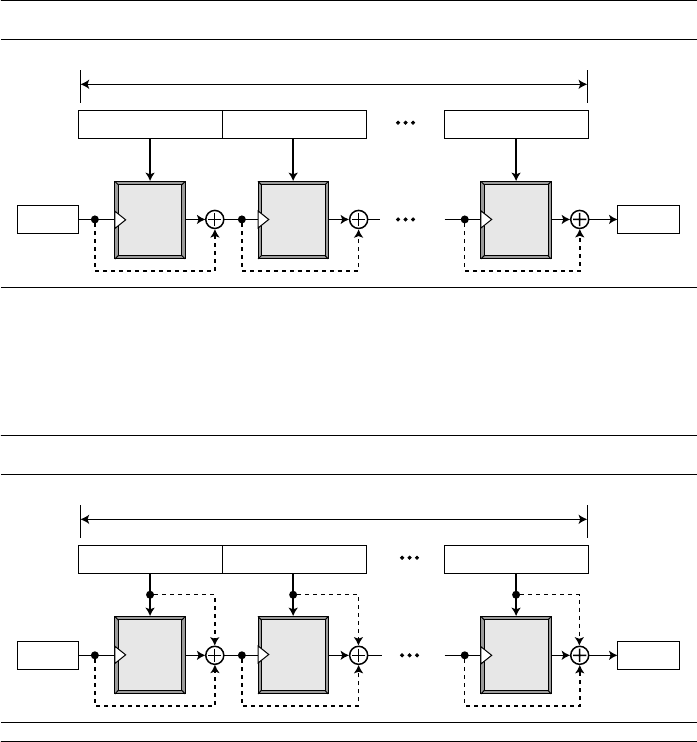
SECTION 12.2 SHA-512 367
example, AES is a good candidate for this purpose. Figure 12.4 shows the Matyas-
Meyer-Oseas scheme.
Miyaguchi-Preneel Scheme The Miyaguchi-Preneel scheme is an extended ver-
sion of Matyas-Meyer-Oseas. To make the algorithm stronger against attack, the plain-
text, the cipher key, and the ciphertext are all exclusive-ored together to create the new
digest. This is the scheme used by the Whirlpool hash function. Figure 12.5 shows the
Miyaguchi-Preneel scheme.
12.2 SHA-512
SHA-512 is the version of SHA with a 512-bit message digest. This version, like the
others in the SHA family of algorithms, is based on the Merkle-Damgard scheme. We
have chosen this particular version for discussion because it is the latest version, it has a
more complex structure than the others, and its message digest is the longest. Once the
structure of this version is understood, it should not be difficult to understand the struc-
tures of the other versions. For characteristics of SHA-512 see Table 12.1.
Introduction
SHA-512 creates a digest of 512 bits from a multiple-block message. Each block is
1024 bits in length, as shown in Figure 12.6.
Figure 12.4 Matyas-Meyer-Oseas
scheme
Figure 12.5 Miyaguchi-Preneel
scheme
n bits
n bits
n bits
m bits
Message
di
g
est
H
0
m bits
H
t
Padded message: t blocks
M
1
M
2
M
t
K C
Encrypt
P
K C
Encrypt
P
K C
Encrypt
P
n bits n bits n bits
m bits
Message
di
g
est
H
0
m bits
H
t
Padded message: t blocks
M
1
M
2
M
t
K C
Encrypt
P
K C
Encrypt
P
K C
Encrypt
P

368 CHAPTER 12 CRYPTOGRAPHIC HASH FUNCTIONS
The digest is initialized to a predetermined value of 512 bits. The algorithm mixes
this initial value with the first block of the message to create the first intermediate mes-
sage digest of 512 bits. This digest is then mixed with the second block to create the
second intermediate digest. Finally, the (N − 1)th digest is mixed with the Nth block to
create the Nth digest. When the last block is processed, the resulting digest is the mes-
sage digest for the entire message.
Message Preparation
SHA-512 insists that the length of the original message be less than 2
128
bits. This
means that if the length of a message is equal to or greater than 2
128
, it will not be pro-
cessed by SHA-512. This is not usually a problem because 2
128
bits is probably larger
than the total storage capacity of any system.
Example 12.1
This example shows that the message length limitation of SHA-512 is not a serious problem.
Suppose we need to send a message that is 2
128
bits in length. How long does it take for a com-
munications network with a data rate of 2
64
bits per second to send this message?
Solution
A communications network that can send 2
64
bits per second is not yet available. Even if it were,
it would take many years to send this message. This tells us that we do not need to worry about
the SHA-512 message length restriction.
Example 12.2
This example also concerns the message length in SHA-512. How many pages are occupied by a
message of 2
128
bits?
Figure 12.6
Message digest creation SHA-512
SHA-512 creates a 512-bit message digest out of a message less than 2
128
.
512 bits
Initial
value
Block 1 Block 2 Block N
1024 bits 1024 bits 1024 bits
Message
di
g
est
512 bits 512 bits
Compression
function
Compression
function
Compression
function
Augmented message: multiple of 1024-bit blocks
512 bits
512 bits

SECTION 12.2 SHA-512 369
Solution
Suppose that a character is 64, or 2
6
, bits. Each page is less than 2048, or approximately 2
12
,
characters. So 2
128
bits need at least 2
128
/ 2
18
,
or 2
110
, pages. This again shows that we need not
worry about the message length restriction.
Length Field and Padding
Before the message digest can be created, SHA-512 requires the addition of a 128-bit
unsigned-integer length field to the message that defines the length of the message in
bits. This is the length of the original message before padding. An unsigned integer
field of 128 bits can define a number between 0 and 2
128
− 1, which is the maximum
length of the message allowed in SHA-512. The length field defines the length of the
original message before adding the length field or the padding (Figure 12.7).
Before the addition of the length field, we need to pad the original message to
make the length a multiple of 1024. We reserve 128 bits for the length field, as shown in
Figure 12.7. The length of the padding field can be calculated as follows. Let |M| be the
length of the original message and |P| be the length of the padding field.
The format of the padding is one 1 followed by the necessary number of 0s.
Example 12.3
What is the number of padding bits if the length of the original message is 2590 bits?
Solution
We can calculate the number of padding bits as follows:
The padding consists of one 1 followed by 353 0’s.
Example 12.4
Do we need padding if the length of the original message is already a multiple of 1024 bits?
Solution
Yes we do, because we need to add the length field. So padding is needed to make the new block
a multiple of 1024 bits.
Figure 12.7
Padding and length field in SHA-512
(|M| + |P| + 128) = 0 mod 1024 → |P| = (− |M| − 128) mod 1024
|P| = (− 2590 −128) mod 1024 = −2718 mod 1024 = 354
Original
message
Padding
1000000000 ... 00000
Length < 2
128
Length: variable Length = 128
Length of
original message
Multiple of 1024 bits

370 CHAPTER 12 CRYPTOGRAPHIC HASH FUNCTIONS
Example 12.5
What is the minimum and maximum number of padding bits that can be added to a message?
Solution
a. The minimum length of padding is 0 and it happens when (−M − 128) mod 1024 is 0.
This means that |M| = −128 mod 1024 = 896 mod 1024 bits. In other words, the last
block in the original message is 896 bits. We add a 128-bit length field to make the block
complete.
b. The maximum length of padding is 1023 and it happens when (−|M| −128) = 1023 mod
1024. This means that the length of the original message is |M| = (−128 −1023) mod
1024 or the length is |M| = 897 mod 1024. In this case, we cannot just add the length
field because the length of the last block exceeds one bit more than 1024. So we need to
add 897 bits to complete this block and create a second block of 896 bits. Now the
length can be added to make this block complete.
Words
SHA-512 operates on words; it is word oriented. A word is defined as 64 bits. This
means that, after the padding and the length field are added to the message, each block
of the message consists of sixteen 64-bit words. The message digest is also made of
64-bit words, but the message digest is only eight words and the words are named A, B,
C, D, E, F, G, and H, as shown in Figure 12.8.
Word Expansion
Before processing, each message block must be expanded. A block is made of 1024
bits, or sixteen 64-bit words. As we will see later, we need 80 words in the processing
phase. So the 16-word block needs to be expanded to 80 words, from W
0
to W
79
. Fig-
ure 12.9 shows the word-expansion process. The 1024-bit block becomes the first 16
words; the rest of the words come from already-made words according to the operation
shown in the figure.
Figure 12.8 A message block and the digest as words
SHA-252 is word-oriented. Each block is 16 words; the digest is only 8 words.
Message
digest
8 words, each of 64 bits = 512 bits
A B C D
E
F
G
H
16 words, each of 64 bits = 1024 bits
Message
block

SECTION 12.2 SHA-512 371
Example 12.6
Show how W
60
is made.
Solution
Each word in the range W
16
to W
79
is made from four previously-made words. W
60
is made as
Message Digest Initialization
The algorithm uses eight constants for message digest initialization. We call these con-
stants A
0
to H
0
to match with the word naming used for the digest. Table 12.2 shows
the value of these constants.
The reader may wonder where these values come from. The values are calculated
from the first eight prime numbers (2, 3, 5, 7, 11, 13, 17, and 19). Each value is the frac-
tion part of the square root of the corresponding prime number after converting to
binary and keeping only the first 64 bits. For example, the eighth prime is 19, with
the square root (19)
1/2
= 4.35889894354. Converting the number to binary with only
64 bits in the fraction part, we get
SHA-512 keeps the fraction part, (
5BE0CD19137E2179)
16
,
as an unsigned integer.
Figure 12.9
Word expansion in SHA-512
W
60
= W
44
⊕ RotShift
1-8-7
(W
45
) ⊕ W
53
⊕ RotShift
19-61-6
(W
58
)
Table 12.2
Values of constants in message digest initialization of SHA-512
Buffer Value (in hexadecimal) Buffer Value (in hexadecimal)
A
0
6A09E667F3BCC908 E
0
510E527FADE682D1
B
0
BB67AE8584CAA73B F
0
9B05688C2B3E6C1F
C
0
3C6EF372EF94F82B G
0
1F83D9ABFB41BD6B
D
0
A54FE53A5F1D36F1 H
0
5BE0CD19137E2179
(100.0101 1011 1110 . . . 1001)
2
→ (4.5BE0CD19137E2179)
16
W
0
W
1
Block of 16 words = 1024 bits
W
i−16
W
i−7
RotR
i
(x): Right-rotation of the argument x by i bits
ShL
i
(x): Shift-left of the argument x by i bits and padding the left by 0’s.
W
i−15
RotShift
1-8-7
(W
i−15
)
W
i−2
RotShift
19−61−6
(W
i−2
)
RotShift
1-m-n
(x): RotR
l
(x) RotR
m
(x) ShL
n
(x)
W
15
W
16
W
i
W
79

372 CHAPTER 12 CRYPTOGRAPHIC HASH FUNCTIONS
Compression Function
SHA-512 creates a 512-bit (eight 64-bit words) message digest from a multiple-block
message where each block is 1024 bits. The processing of each block of data in SHA-
512 involves 80 rounds. Figure 12.10 shows the general outline for the compression
function. In each round, the contents of eight previous buffers, one word from the
expanded block (W
i
), and one 64-bit constant (K
i
) are mixed together and then oper-
ated on to create a new set of eight buffers. At the beginning of processing, the values
of the eight buffers are saved into eight temporary variables. At the end of the process-
ing (after step 79), these values are added to the values created from step 79. We call
this last operation the final adding, as shown in the figure.
Figure 12.10 Compression function in SHA-512
A B C D E F H G
A B C D E F H G
A B C D E F H G
A B C D E F H G
Round 0
W
0
K
0
W
79
K
79
Round 79
Results of the previous block or the initial digest
Values for the next block or the final di
g
est
Final
adding

SECTION 12.2 SHA-512 373
Structure of Each Round
In each round, eight new values for the 64-bit buffers are created from the values of the
buffers in the previous round. As Figure 12.11 shows, six buffers are the exact copies of
one of the buffers in the previous round as shown below:
Two of the new buffers, A and E, receive their inputs from some complex functions
that involve some of the previous buffers, the corresponding word for this round (W
i
),
and the corresponding constant for this round (K
i
). Figure 12.11 shows the structure of
each round.
A → B B → C C → D E → F F → G G → H
Figure 12.11 Structure of each round in SHA-512
A B C D E F G H
W
i
X
(to A)
Round
X
(See below)
Y
(See below)
Y
(to E)
K
i
A B C
Majority
(A, B, C)
Mixer 1
Mixer 2
D
H E F G
Conditional
(E, F, G)
Rotate (A) Rotate (E)
Majority (x, y, z)
Rotate (x)
addition modulo 2
64
Conditional (x, y, z)
RotR
28
(x) RotR
34
(x)
RotR
39
(x)
(x AND y) (NOT x AND z)
(x AND y) ( y AND z) (z AND x)
RotR
i
(x): Right-rotation of the argument x by i bits
A B C D E F G H

374 CHAPTER 12 CRYPTOGRAPHIC HASH FUNCTIONS
There are two mixers, three functions, and several operators. Each mixer combines
two functions. The description of the functions and operators follows:
1. The Majority function, as we call it, is a bitwise function. It takes three corre-
sponding bits in three buffers (A, B, and C) and calculates
(A
j
AND B
j
) ⊕ (B
j
AND C
j
) ⊕ (C
j
AND A
j
)
The resulting bit is the majority of three bits. If two or three bits are 1’s, the result-
ing bit is 1; otherwise it is 0.
2. The Conditional function, as we call it, is also a bitwise function. It takes three cor-
responding bits in three buffers (E, F, and G) and calculates
(E
j
AND F
j
) ⊕ (NOT E
j
AND G
j
)
The resulting bit is the logic “If E
j
then F
j
; else G
j
”.
3. The Rotate function, as we call it, right-rotates the three instances of the same
buffer (A or E) and applies the exclusive-or operation on the results.
Rotate (A): RotR
28
(A) ⊕ RotR
34
(A) ⊕ RotR
29
(A)
Rotate (E): RotR
28
(E) ⊕ RotR
34
(E) ⊕ RotR
29
(E)
4. The right-rotation function, RotR
i
(x), is the same as the one we used in the word-
expansion process. It right-rotates its argument i bits; it is actually a circular shift-
right operation.
5. The addition operator used in the process is addition modulo 2
64
. This means that
the result of adding two or more buffers is always a 64-bit word.
6. There are 80 constants, K
0
to K
79
, each of 64 bits as shown in Table 12.3 in hexa-
decimal format (four in a row). Similar to the initial values for the eight digest
buffers, these values are calculated from the first 80 prime numbers (2, 3,…, 409).
Table 12.3
Eighty constants used for eighty rounds in SHA-512
428A2F98D728AE22
3956C25BF348B538
D807AA98A3030242
72BE5D74F27B896F
E49B69C19EF14AD2
2DE92C6F592B0275
983E5152EE66DFAB
C6E00BF33DA88FC2
27B70A8546D22FFC
650A73548BAF63DE
A2BFE8A14CF10364
D192E819D6EF5218
19A4C116B8D2D0C8
391C0CB3C5C95A63
748F82EE5DEFB2FC
90BEFFFA23631E28
CA273ECEEA26619C
06F067AA72176FBA
28DB77F523047D84
4CC5D4BECB3E42B6
7137449123EF65CD
59F111F1B605D019
12835B0145706FBE
80DEB1FE3B1696B1
EFBE4786384F25E3
4A7484AA6EA6E483
A831C66D2DB43210
D5A79147930AA725
2E1B21385C26C926
766A0ABB3C77B2A8
A81A664BBC423001
D69906245565A910
1E376C085141AB53
4ED8AA4AE3418ACB
78A5636F43172F60
A4506CEBDE82BDE9
D186B8C721C0C207
0A637DC5A2C898A6
32CAAB7B40C72493
4597F299CFC657E2
B5C0FBCFEC4D3B2F
923F82A4AF194F9B
243185BE4EE4B28C
9BDC06A725C71235
0FC19DC68B8CD5B5
5CB0A9DCBD41FBD4
B00327C898FB213F
06CA6351E003826F
4D2C6DFC5AC42AED
81C2C92E47EDAEE6
C24B8B70D0F89791
F40E35855771202A
2748774CDF8EEB99
5B9CCA4F7763E373
84C87814A1F0AB72
BEF9A3F7B2C67915
EADA7DD6CDE0EB1E
113F9804BEF90DAE
3C9EBE0A15C9BEBC
5FCB6FAB3AD6FAEC
E9B5DBA58189DBBC
AB1C5ED5DA6D8118
550C7DC3D5FFB4E2
C19BF174CF692694
240CA1CC77AC9C65
76F988DA831153B5
BF597FC7BEEF0EE4
142929670A0E6E70
53380D139D95B3DF
92722C851482353B
C76C51A30654BE30
106AA07032BBD1B8
34B0BCB5E19B48A8
682E6FF3D6B2B8A3
8CC702081A6439EC
C67178F2E372532B
F57D4F7FEE6ED178
1B710B35131C471B
431D67C49C100D4C
6C44198C4A475817

SECTION 12.2 SHA-512 375
Each value is the fraction part of the cubic root of the corresponding prime number
after converting it to binary and keeping only the first 64 bits. For example, the
80th prime is 409, with the cubic root (409)
1/3
= 7.42291412044. Converting this
number to binary with only 64 bits in the fraction part, we get
(111.0110 1100 0100 0100 . . . 0111)
2
→ (7.6C44198C4A475817)
16
SHA-512 keeps the fraction part, (6C44198C4A475817)
16
, as an unsigned integer.
Example 12.7
We apply the Majority function on buffers A, B, and C. If the leftmost hexadecimal digits of these
buffers are 0x7, 0xA, and 0xE, respectively, what is the leftmost digit of the result?
Solution
The digits in binary are 0111, 1010, and 1110.
a. The first bits are 0, 1, and 1. The majority is 1. We can also prove it using the definition
of the Majority function:
b. The second bits are 1, 0, and 1. The majority is 1.
c. The third bits are 1, 1, and 1. The majority is 1.
d. The fourth bits are 1, 0, and 0. The majority is 0.
The result is 1110, or 0xE in hexadecimal.
Example 12.8
We apply the Conditional function on E, F, and G buffers. If the leftmost hexadecimal digits of
these buffers are 0x9, 0xA, and 0xF respectively, what is the leftmost digit of the result?
Solution
The digits in binary are 1001, 1010, and 1111.
a. The first bits are 1, 1, and 1. Since E
1
= 1, the result is F
1
, which is 1. We can also use the
definition of the Condition function to prove the result:
b. The second bits are 0, 0, and 1. Since E
2
is 0, the result is G
2
, which is 1.
c. The third bits are 0, 1, and 1. Since E
3
is 0, the result is G
3
, which is 1.
d. The fourth bits are 1, 0, and 1. Since E
4
is 1, the result is F
4
, which is 0.
The result is 1110, or 0xE in hexadecimal.
Analysis
With a message digest of 512 bits, SHA-512 expected to be resistant to all attacks,
including collision attacks. It has been claimed that this version’s improved design
makes it more efficient and more secure than the previous versions. However, more
research and testing are needed to confirm this claim.
(0
AND 1) ⊕ (1
AND 1) ⊕ (1
AND 0) = 0 ⊕ 1
⊕ 0 = 1
(1 AND 1) ⊕ (NOT 1
AND 1) = 1 ⊕ 0 = 1

376 CHAPTER 12 CRYPTOGRAPHIC HASH FUNCTIONS
12.3 WHIRLPOOL
Whirlpool is designed by Vincent Rijmen and Paulo S. L. M. Barreto. It is endorsed by
the New European Schemes for Signatures, Integrity, and Encryption (NESSIE).
Whirlpool is an iterated cryptographic hash function, based on the Miyaguchi-Preneel
scheme, that uses a symmetric-key block cipher in place of the compression function.
The block cipher is a modified AES cipher that has been tailored for this purpose.
Figure 12.12 shows the Whirlpool hash function.
Preparation
Before starting the hash algorithm, the message needs to be prepared for processing.
Whirlpool requires that the length of the original message be less than 2
256
bits. A mes-
sage needs to be padded before being processed. The padding is a single 1-bit followed
by the necessary numbers of 0-bits to make the length of the padding an odd multiple
of 256 bits. After padding, a block of 256 bits is added to define the length of the origi-
nal message. This block is treated as an unsigned number.
After padding and adding the length field, the augmented message size is an even
multiple of 256 bits or a multiple of 512 bits. Whirlpool creates a digest of 512 bits
from a multiple 512-bit block message. The 512-bit digest, H
0
, is initialized to all 0’s.
This value becomes the cipher key for encrypting the first block. The ciphertext result-
ing from encrypting each block becomes the cipher key for the next block after being
exclusive-ored with the previous cipher key and the plaintext block. The message digest
is the final 512-bit ciphertext after the last exclusive-or operation.
Figure 12.12 Whirlpool hash function
512 bits 512 bits 512 bits
512 bits
All 0’s
H
0
512 bits
Message
digest
H
Message with padding and length field: multiple of 512-bit blocks
Original message
Padding
Message
length
Odd multiple of 256-bit blocks 256 bits
Whirlpool
cipher
Encryption
Whirlpool
cipher
Encryption
Whirlpool
cipher
Encryption

SECTION 12.3 WHIRLPOOL 377
Whirlpool Cipher
The Whirlpool cipher is a non-Feistel cipher like AES that was mainly designed as a
block cipher to be used in a hash algorithm. Instead of giving the whole description of
this cipher, we just assume that the reader is familiar with AES from Chapter 7. Here the
Whirlpool cipher is compared with the AES cipher and their differences are mentioned.
Rounds
Whirlpool is a round cipher that uses 10 rounds. The block size and key size are 512 bits.
The cipher uses 11 round keys, K
0
to K
10
, each of 512 bits. Figure 12.13 shows the
general design of the Whirlpool cipher.
States and Blocks
Like the AES cipher, the Whirlpool cipher uses states and blocks. However, the size of
the block or state is 512 bits. A block is considered as a row matrix of 64 bytes; a state
is considered as a square matrix of 8 × 8 bytes. Unlike AES, the block-to-state or state-
to-block transformation is done row by row. Figure 12.14 shows the block, the state,
and the transformation in the Whirlpool cipher.
Structure of Each Round
Figure 12.15 shows the structure of each round. Each round uses four transformations.
SubBytes Like in AES, SubBytes provide a nonlinear transformation. A byte is rep-
resented as two hexadecimal digits. The left digit defines the row and the right digit
defines the column of the substitution table. The two hexadecimal digits at the junction
of the row and the column are the new byte. Figure 12.16 shows the idea.
Figure 12.13 General idea of the Whirlpool cipher
Cipher key
(512 bits)
Round keys
(512 bits)
512-bit plaintext
Whirlpool
512-bit ciphertext
K
1
K
2
K
10
K
0
Pre-round
transformation
Round 1
Round 2
Round 10
Key expansion

378 CHAPTER 12 CRYPTOGRAPHIC HASH FUNCTIONS
Figure 12.14 Block and state in the Whirlpool cipher
Figure 12.15 Structure of each round in the Whirlpool cipher
State
s
0,4
s
0,5
s
0,6
s
0,7
s
1,4
s
1,5
s
1,6
s
1,7
s
2,4
s
2,5
s
2,6
s
2,7
s
3,4
s
3,5
s
3,6
s
3,7
s
0,0
s
0,1
s
0,2
s
0,3
s
1,0
s
1,1
s
1,2
s
1,3
s
2,0
s
2,1
s
2,2
s
2,3
s
3,0
s
3,1
s
3,2
s
3,3
s
4,0
s
4,1
s
4,2
s
4,3
s
5,0
s
5,1
s
5,2
s
5,3
s
6,0
s
6,1
s
6,2
s
6,3
s
7,0
s
7,1
s
7,2
s
7,3
s
4,4
s
4,5
s
4,6
s
4,7
s
5,4
s
5,5
s
5,6
s
5,7
s
6,4
s
6,5
s
6,6
s
6,7
s
7,4
s
7,5
s
7,6
s
7,7
Insertion and
extraction is row by row
s
i/8, i mod 8
b
i
b
i × 8 + j
= s
i, j
Block
b
0
b
1
b
7
b
8
b
9
b
15
b
56
b
57
b
63
Block
b
0
b
1
b
7
b
8
b
9
b
15
b
56
b
57
b
63
Round
State
State
State
State
State
Round key
SubBytes
ShiftColumn
MixRow
AddRoundKey

SECTION 12.3 WHIRLPOOL 379
In the SubBytes transformation, the state is treated as an 8 × 8 matrix of bytes.
Transformation is done one byte at a time. The contents of each byte are changed, but
the arrangement of the bytes in the matrix remains the same. In the process, each byte
is transformed independently; we have 64 distinct byte-to-byte transformations.
Table 12.4 shows the substitution table (S-Box) for SubBytes transformation. The
transformation definitely provides confusion effect. For example, two bytes, 5A
16
and
5B
16
, which differ only in one bit (the rightmost bit), are transformed to 5B
16
and 88
16
,
which differ in five bits.
Figure 12.16 SubBytes transformations in the Whirlpool cipher
Table 12.4 SubBytes transformation table (S-Box)
0 1 2 3 4 5 6 7 8 9 A B C D E F
0 18 23 C6 E8 87 B8 01 4F 36 A6 D2 F5 79 6F 91 52
1 16 BC 9B 8E A3 0C 7B 35 1D E0 D7 C2 2E 4B FE 57
2 15 77 37 E5 9F F0 4A CA 58 C9 29 0A B1 A0 6B 85
3 BD 5D 10 F4 CB 3E 05 67 E4 27 41 8B A7 7D 95 C8
4 FB EF 7C 66 DD 17 47 9E CA 2D BF 07 AD 5A 83 33
5 63 02 AA 71 C8 19 49 C9 F2 E3 5B 88 9A 26 32 B0
6 E9 0F D5 80 BE CD 34 48 FF 7A 90 5F 20 68 1A AE
7 B4 54 93 22 64 F1 73 12 40 08 C3 EC DB A1 8D 3D
8 97 00 CF 2B 76 82 D6 1B B5 AF 6A 50 45 F3 30 EF
9 3F 55 A2 EA 65 BA 2F C0 DE 1C FD 4D 92 75 06 8A
A B2 E6 0E 1F 62 D4 A8 96 F9 C5 25 59 84 72 39 4C
B 5E 78 38 8C C1 A5 E2 61 B3 21 9C 1E 43 C7 FC 04
C 51 99 6D 0D FA DF 7E 24 3B AB CE 11 8F 4E B7 EB
D 3C 81 94 F7 9B 13 2C D3 E7 6E C4 03 56 44 7E A9
E 2A BB C1 53 DC 0B 9D 6C 31 74 F6 46 AC 89 14 E1
F 16 3A 69 09 70 B6 C0 ED CC 42 98 A4 28 5C F8 86
SubBytes
Table
cd
16
a
16
b
16
State
State
ab
16

380 CHAPTER 12 CRYPTOGRAPHIC HASH FUNCTIONS
The entries in Table 12.4 can be calculated algebraically using the GF(2
4
) field
with the irreducible polynomials (x
4
+ x + 1) as shown in Figure 12.17. Each hexadeci-
mal digit in a byte is the input to a minibox (E and E
−1
). The results are fed into another
minibox, R. The E boxes calculate the exponential of input hexadecimal; the R box
uses a pseudorandom number generator.
The E
−1
box is just the inverse of the E box where the roles of input and output are
changed. The input/output values for boxes are also tabulated in Figure 12.17.
ShiftColumns To provide permutation, Whirlpool uses the ShiftColumns transforma-
tion, which is similar to the ShiftRows transformation in AES, except that the columns
instead of rows are shifted. Shifting depends on the position of the column. Column 0
goes through 0-byte shifting (no shifting), while column 7 goes through 7-byte shifting.
Figure 12.18 shows the shifting transformation.
E(input) = (x
3
+ x + 1)
input
mod (x
4
+ x + 1) if input ≠ 0xF
E(0xF) = 0
Figure 12.17 SubBytes in the Whirlpool cipher
E
0 1 2 3 4 5 6 7 8 9 A B C D E F
1 B 9 C D 6 F 3 E 8 7 4 A 2 5 0
0 1 2 3 4 5 6 7 8 9 A B C D E F
F 0 D 7 B E 5 A 9 2 C 1 3 4 8 6
0 1 2 3 4 5 6 7 8 9 A B C D E F
7 C B D E 4 9 F 6 3 8 A 2 5 1 0
a
1
a
2
a
3
a
4
d
1
E
E
−1
E
−1
R
E box
E
−1
box
R box
Input
Output
Input
Output
Input
Output
b
1
b
2
b
3
b
4
d
2
d
3
d
4
c
1
c
2
c
3
c
4

SECTION 12.3 WHIRLPOOL 381
MixRows The MixRows transformation has the same effect as the MixColumns
transformation in AES: it diffuses the bits. The MixRows transformation is a matrix
transformation where bytes are interpreted as 8-bit words (or polynomials) with coeffi-
cients in GF(2). Multiplication of bytes is done in GF(2
8
), but the modulus is different
from the one used in AES. The Whirlpool cipher uses (0x11D) or (x
8
+ x
4
+ x
3
+ x
2
+ 1)
as the modulus. Addition is the same as XORing of 8-bit words. Figure 12.19 shows the
MixRows transformation.
The figure shows multiplication of a single row by the constant matrix; the mul-
tiplication can actually be done by multiplying the whole state by the constant
Figure 12.18 ShiftColumns transformation in the Whirlpool cipher
Figure 12.19 MixRows transformation in the Whirlpool cipher
State
State
ShiftColumn
Shift down
MixRows
Constant
Constant matrix
State State
01 01 04 01 08 05 02 09
09 01 01 04 01 08 05 02
02 09 01 01 04 01 08 05
05 02 09 01 01 04 01 08
08 05 02 09 01 01 04 01
01 08 05 02 09 01 01 04
04 01 08 05 02 09 01 01
01 04 01 08 05 02 09 01
= ×

382 CHAPTER 12 CRYPTOGRAPHIC HASH FUNCTIONS
matrix. Note that in the constant matrix, each row is the circular right shift of the
previous row.
AddRoundKey The AddRoundKey transformation in the Whirlpool cipher is done
byte by byte, because each round key is also a state of an 8 × 8 matrix. Figure 12.20
shows the process. A byte from the data state is added, in GF(2
8
) field, to the corre-
sponding byte in the round-key state. The result is the new byte in the new state.
Key Expansion
As Figure 12.21 shows, the key-expansion algorithm in Whirlpool is totally different
from the algorithm in AES. Instead of using a new algorithm for creating round keys,
Whirlpool uses a copy of the encryption algorithm (without the pre-round) to create
the round keys. The output of each round in the encryption algorithm is the round key
for that round. At first glance, this looks like a circular definition; where do the round
keys for the key expansion algorithm come from? Whirlpool has elegantly solved this
problem by using ten round constants (RCs) as the virtual round keys for the key-
expansion algorithm. In other words, the key-expansion algorithm uses constants as
the round keys and the encryption algorithm uses the output of each round of the key-
expansion algorithm as the round keys. The key-generation algorithm treats the cipher
key as the plaintext and encrypts it. Note that the cipher key is also K
0
for the
encryption algorithm.
Round Constants Each round constant, RC
r
is an 8 × 8 matrix where only the first
row has non-zero values. The rest of the entries are all 0’s. The values for the first
row in each constant matrix can be calculated using the SubBytes transformation
(Table 12.4).
Figure 12.20 AddRoundKey transformation in the Whirlpool cipher
RC
round
[row, column] = SubBytes (8(round −1) + column) if row = 0
RC
round
[row, column] = 0 if row ≠ 0
AddRoundKey
Key byte
=
⊕
StateState

SECTION 12.3 WHIRLPOOL 383
In other words, RC
1
uses the first eight entries in the SubBytes transformation table
[Table 12.4]; RC
2
uses the second eight entries, and so on. For example, Figure 12.22
shows RC
3
, where the first row is the third eight entries in the SubBytes table.
Figure 12.21 Key expansion in the Whirlpool cipher
Figure 12.22 Round constant for the third round
Round 1Round 10
Plaintext
Ciphertext
Encryption
Key generation
AddRoundKey
AddRoundKey
SubByte
ShiftColumns
MixRows
AddRoundKey
SubByte
ShiftColumns
MixRows
Round 1
Round 10
Cipher key
RC
1
K
0
K
1
K
10
RC
10
AddRoundKey
SubByte
ShiftColumns
MixRows
AddRoundKey
SubByte
ShiftColumns
MixRows
RC
3
=
1D E0 D7 C2 2E 4B FE 57
00 00 00 00 00 00 00 00
00 00 00 00 00 00 00 00
00 00 00 00 00 00 00 00
00 00 00 00 00 00 00 00
00 00 00 00 00 00 00 00
00 00 00 00 00 00 00 00
00 00 00 00 00 00 00 00

384 CHAPTER 12 CRYPTOGRAPHIC HASH FUNCTIONS
Summary
Table 12.5 summarizes some characteristics of the Whirlpool cipher.
Analysis
Although Whirlpool has not been extensively studied or tested, it is based on a robust
scheme (Miyaguchi-Preneel), and for a compression function uses a cipher that is
based on AES, a cryptosystem that has been proved very resistant to attacks. In addi-
tion, the size of the message digest is the same as for SHA-512. Therefore it is expected
to be a very strong cryptographic hash function. However, more testing and researches
are needed to confirm this. The only concern is that Whirlpool, which is based on a
cipher as the compression function, may not be as efficient as SHA-512, particularly
when it is implemented in hardware.
12.4 RECOMMENDED READING
For more details about subjects discussed in this chapter, we recommend the following
books and websites. The items enclosed in brackets refer to the reference list at the end
of the book.
Books
Several books give a good coverage of cryptographic hash functions, including [Sti06],
[Sta06], [Sch99], [Mao04], [KPS02], [PHS03], and [MOV97].
WebSites
The following websites give more information about topics discussed in this chapter.
Table 12.5
Main characteristics of the Whirlpool cipher
Block size: 512 bits
Cipher key size: 512 bits
Number of rounds: 10
Key expansion: using the cipher itself with round constants as round keys
Substitution: SubBytes transformation
Permutation: ShiftColumns transformation
Mixing: MixRows transformation
Round Constant: cubic roots of the first eighty prime numbers
http://www.unixwiz.net/techtips/iguide-crypto-hashes.html
http://www.faqs.org/rfcs/rfc4231.html
http://www.itl.nist.gov/fipspubs/fip180-1.htm
http://www.ietf.org/rfc/rfc3174.txt
http://paginas.terra.com.br/informatica/paulobarreto/WhirlpoolPage.html

SECTION 12.6 SUMMARY 385
12.5 KEY TERMS
12.6 SUMMARY
❏ All cryptographic hash functions must create a fixed-size digest out of a variable-
size message. Creating such a function is best accomplished using iteration. A
compression function is repeatedly used to create the digest. The scheme is
referred to as an iterated hash function.
❏ The Merkle-Damgard scheme is an iterated cryptographic hash function that
is collision resistant if the compression function is collision resistant. The Merkle-
Damgard scheme is the basis for many cryptographic hash functions today.
❏ There is a tendency to use two different approaches in designing the compression
function. In the first approach, the compression function is made from scratch: it is
particularly designed for this purpose. In the second approach, a symmetric-key
block cipher serves instead of a compression function.
❏ A set of cryptographic hash functions uses compression functions that are made
from scratch. These compression functions are specifically designed for the pur-
pose they serve. Some examples are the Message Digest (MD) group, the Secure
Hash Algorithm (SHA) group, RIPEMD, and HAVAL.
❏ An iterated cryptographic hash function can use a symmetric-key block cipher
instead of a compression function. Several schemes for this approach have been
proposed, including the Rabin scheme, Davies-Meyer scheme, Matyas-Meyer-
Oseas scheme, and Miyaguchi-Preneel scheme.
AddRoundKey RACE Integrity Primitives Evaluation
compression function Message Digest (RIPMED)
Davies-Meyer scheme RIPEMD-160
HAVAL Secure Hash Algorithm (SHA)
iterated cryptographic hash function Secure Hash Standard (SHS)
Matyas-Meyer-Oseas scheme SHA-1
MD2 SHA-224
MD4 SHA-256
MD5 SHA-384
Merkle-Damgard scheme SHA-512
Message Digest (MD) ShiftColumns
MixRows SubBytes
Miyaguchi-Preneel scheme Whirlpool cipher
New European Schemes for Signatures, Whirlpool cryptographic hash function
Integrity, and Encryption (NESSIE) word expansion
Rabin scheme

386 CHAPTER 12 CRYPTOGRAPHIC HASH FUNCTIONS
❏ One of the promising cryptographic hash functions is SHA-512 with a 512-bit
message digest based on the Merkle-Damgard scheme. It is made from scratch for
this purpose.
❏ Another promising cryptographic hash function is Whirlpool, which is endorsed
by NESSIE. Whirlpool is an iterated cryptographic hash function, based on the
Miyaguchi-Preneel scheme, that uses a symmetric-key block cipher in place of
the compression function. The block cipher is a modified AES cipher tailored for
this purpose.
12.7 PRACTICE SET
Review Questions
1. Define a cryptographic hash function.
2. Define an iterated cryptographic hash function.
3. Describe the idea of the Merkle-Damgard scheme and why this idea is so impor-
tant for the design of a cryptographic hash function.
4. List some family of hash functions that do not use a cipher as the compression
function.
5. List some schemes that have been designed to use a block cipher as the compres-
sion function.
6. List the main features of the SHA-512 cryptographic hash function. What kind of
compression function is used in SHA-512?
7. List some features of the Whirlpool cryptographic hash function. What kind of
compression function is used in Whirlpool?
8. Compare and contrast features of SHA-512 and Whirlpool cryptographic hash
functions.
Exercises
9. In SHA-512, show the value of the length field in hexadecimal for the following
message lengths:
a. 1000 bits
b. 10,000 bits
c. 1000,000 bits
10. In Whirlpool, show the value of the length field in hexadecimal for the following
message lengths:
a. 1000 bits
b. 10,000 bits
c. 1000,000 bits
11. What is the padding for SHA-512 if the length of the message is:
a. 5120 bits
b. 5121 bits
c. 6143 bits
SECTION 12.7 PRACTICE SET 387
12. What is the padding for Whirlpool if the length of the message is:
a. 5120 bits
b. 5121 bits
c. 6143 bits
13. In each of the following cases, show that if two messages are the same, their last
blocks are also the same (after padding and adding the length field):
a. The hash function is SHA-512.
b. The hash function is Whirlpool.
14. Calculate G
0
in Table 12.2 using the seventh prime (17).
15. Compare the compression function of SHA-512 without the last operation (final
adding) with a Feistel cipher of 80 rounds. Show the similarities and differences.
16. The compression function used in SHA-512 (Figure 12.10) can be thought of as an
encrypting cipher with 80 rounds. If the words, W
0
to W
79
, are thought of as round
keys, which one of the schemes described in this chapter (Rabin, Davies-Meyer,
Matyas-Meyer Oseas, or Miyaguchi-Preneel) does it resemble? Hint: Think about
the effect of the final adding operation.
17. Show that SHA-512 is subject to meet-in-the middle attack if the final adding
operation is removed from the compression function.
18. Make a table similar to Table 12.5 to compare AES and Whirlpool.
19. Show that the third operation does not need to be removed from the tenth round in
Whirlpool cipher, but it must be removed in the AES cipher.
20. Find the result of RotR
12
(x) if
x = 1234 5678 ABCD 2345 3456 5678 ABCD 2468
21. Find the result of ShL
12
(x) if
x = 1234 5678 ABCD 2345 3456 5678 ABCD 2468
22. Find the result of Rotate(x) if
x = 1234 5678 ABCD 2345 3456 5678 ABCD 2468
23. Find the result of Conditional (x, y, z) if
x = 1234 5678 ABCD 2345 3456 5678 ABCD 2468
y = 2234 5678 ABCD 2345 3456 5678 ABCD 2468
x = 3234 5678 ABCD 2345 3456 5678 ABCD 2468
24. Find the result of Majority (x, y, z) if
x = 1234 5678 ABCD 2345 3456 5678 ABCD 2468
y = 2234 5678 ABCD 2345 3456 5678 ABCD 2468
x = 3234 5678 ABCD 2345 3456 5678 ABCD 2468
25. Write a routine (in pseudocode) to calculate RotR
i
(x) in SHA-512 (Figure 12.9).
26. Write a routine (in pseudocode) to calculate ShL
i
(x) in SHA-512 (Figure 12.9).
388 CHAPTER 12 CRYPTOGRAPHIC HASH FUNCTIONS
27. Write a routine (in pseudocode) for the Conditional function in SHA-512
(Figure 12.11).
28. Write a routine (in pseudocode) for the Majority function in SHA-512 (Figure 12.11).
29. Write a routine (in pseudocode) for the Rotate function in SHA-512 (Figure 12.11).
30. Write a routine (in pseudocode) to calculate the initial digest (values of A
0
to H
0
)
in SHA-512 (Table 12.2).
31. Write a routine (in pseudocode) to calculate the eighty constants in SHA-512
(Table 12.3).
32. Write a routine (in pseudocode) for word-expansion algorithm in SHA-512 as
shown in Figure 12.9. Use an array of 80 elements to hold all words.
33. Write a routine (in pseudocode) for the compression function in SHA-512.
34. Write a routine (in pseudocode) to change a block of 512 bits to an 8 × 8 state
matrix (Figure 12.14).
35. Write a routine (in pseudocode) to change an 8 × 8 state matrix to a block of 512
bits (Figure 12.14).
36. Write a routine (in pseudocode) for the SubBytes transformation in the Whirlpool
cipher (Figure 12.16).
37. Write a routine (in pseudocode) for the ShiftColumns transformation in the Whirl-
pool cipher (Figure 12.18).
38. Write a routine (in pseudocode) for the MixRows transformation in the Whirlpool
cipher (Figure 12.19).
39. Write a routine (in pseudocode) for the AddRoundKey transformation in the
Whirlpool cipher (Figure 12.20).
40. Write a routine (in pseudocode) for key expansion in Whirlpool cipher (Figure 12.21).
41. Write a routine (in pseudocode) to create the round constants in the Whirlpool
cipher (Figure 12.20).
42. Write a routine (in pseudocode) for the Whirlpool cipher.
43. Write a routine (in pseudocode) for the Whirlpool cryptographic hash function.
44. Use the Internet (or other available resources) to find information about SHA-1.
Then compare the compression function in SHA-1 with that in SHA-512. What are
the similarities? What are the differences?
45. Use the Internet (or other available resources) to find information about the follow-
ing compression functions, and compare them with SHA-512.
a. SHA-224
b. SHA-256
c. SHA-384
46. Use the Internet (or other available resources) to find information about RIPEMD,
and compare it with SHA-512.
47. Use the Internet (or other available resources) to find information about HAVAL,
and compare it with SHA-512.

389
CHAPTER 13
Digital Signature
Objectives
This chapter has several objectives:
❏ To define a digital signature
❏ To define security services provided by a digital signature
❏ To define attacks on digital signatures
❏ To discuss some digital signature schemes, including RSA, ElGamal,
Schnorr, DSS, and elliptic curve
❏ To describe some applications of digital signatures
We are all familiar with the concept of a signature. A person signs a
document to show that it originated from her or was approved by her. The
signature is proof to the recipient that the document comes from the
correct entity. When a customer signs a check, the bank needs to be sure
that the check is issued by that customer and nobody else. In other words,
a signature on a document, when verified, is a sign of authenticationthe
document is authentic. Consider a painting signed by an artist. The signa-
ture on the art, if authentic, means that the painting is probably authentic.
When Alice sends a message to Bob, Bob needs to check the authen-
ticity of the sender; he needs to be sure that the message comes from
Alice and not Eve. Bob can ask Alice to sign the message electronically.
In other words, an electronic signature can prove the authenticity of
Alice as the sender of the message. We refer to this type of signature as a
digital signature.
In this chapter, we first introduce some issues related to digital signa-
tures and then we walk through different digital signature schemes.

390 CHAPTER 13 DIGITAL SIGNATURE
13.1 COMPARISON
Let us begin by looking at the differences between conventional signatures and digital
signatures.
Inclusion
A conventional signature is included in the document; it is part of the document. When
we write a check, the signature is on the check; it is not a separate document. But when
we sign a document digitally, we send the signature as a separate document. The sender
sends two documents: the message and the signature. The recipient receives both docu-
ments and verifies that the signature belongs to the supposed sender. If this is proven,
the message is kept; otherwise, it is rejected.
Verification Method
The second difference between the two types of signatures is the method of verifying the
signature. For a conventional signature, when the recipient receives a document, she com-
pares the signature on the document with the signature on file. If they are the same, the
document is authentic. The recipient needs to have a copy of this signature on file for
comparison. For a digital signature, the recipient receives the message and the signature.
A copy of the signature is not stored anywhere. The recipient needs to apply a verification
technique to the combination of the message and the signature to verify the authenticity.
Relationship
For a conventional signature, there is normally a one-to-many relationship between a signa-
ture and documents. A person uses the same signature to sign many documents. For a digi-
tal signature, there is a one-to-one relationship between a signature and a message. Each
message has its own signature. The signature of one message cannot be used in another
message. If Bob receives two messages, one after another, from Alice, he cannot use the
signature of the first message to verify the second. Each message needs a new signature.
Duplicity
Another difference between the two types of signatures is a quality called duplicity. In
conventional signature, a copy of the signed document can be distinguished from the
original one on file. In digital signature, there is no such distinction unless there is a
factor of time (such as a timestamp) on the document. For example, suppose Alice
sends a document instructing Bob to pay Eve. If Eve intercepts the document and the
signature, she can replay it later to get money again from Bob.
13.2 PROCESS
Figure 13.1 shows the digital signature process. The sender uses a signing algorithm
to sign the message. The message and the signature are sent to the receiver. The
receiver receives the message and the signature and applies the verifying algorithm

SECTION 13.2 PROCESS 391
to the combination. If the result is true, the message is accepted; otherwise, it is
rejected.
Need for Keys
A conventional signature is like a private “key” belonging to the signer of the docu-
ment. The signer uses it to sign documents; no one else has this signature. The copy of
the signature is on file like a public key; anyone can use it to verify a document, to com-
pare it to the original signature.
In a digital signature, the signer uses her private key, applied to a signing algo-
rithm, to sign the document. The verifier, on the other hand, uses the public key of the
signer, applied to the verifying algorithm, to verify the document.
We can add the private and public keys to Figure 13.1 to give a more complete con-
cept of digital signature (see Figure 13.2). Note that when a document is signed, anyone,
including Bob, can verify it because everyone has access to Alice’s public key. Alice must
not use her public key to sign the document because then anyone could forge her signature.
Can we use a secret (symmetric) key to both sign and verify a signature? The
answer is negative for several reasons. First, a secret key is known by only two entities
(Alice and Bob, for example). So if Alice needs to sign another document and send it to
Ted, she needs to use another secret key. Second, as we will see, creating a secret key
for a session involves authentication, which uses a digital signature. We have a vicious
Figure 13.1
Digital signature process
Figure 13.2
Adding key to the digital signature process
M
(M, S)
M
M: Message
S: Signature
Verifying
algorithm
Signing
algorithm
Bob
Alice
M
(M, S)
M
M: Message
S: Signature
Verifying
algorithm
Signing
algorithm
Alice’s
public key
Alice’s
private key
BobAlice

392 CHAPTER 13 DIGITAL SIGNATURE
cycle. Third, Bob could use the secret key between himself and Alice, sign a document,
send it to Ted, and pretend that it came from Alice.
We should make a distinction between private and public keys as used in digital
signatures and public and private keys as used in a cryptosystem for confidentiality. In
the latter, the private and public keys of the receiver are used in the process. The sender
uses the public key of the receiver to encrypt; the receiver uses his own private key to
decrypt. In a digital signature, the private and public keys of the sender are used. The
sender uses her private key; the receiver uses the sender’s public key.
Signing the Digest
In Chapter 10, we learned that the asymmetric-key cryptosystems are very inefficient
when dealing with long messages. In a digital signature system, the messages are nor-
mally long, but we have to use asymmetric-key schemes. The solution is to sign a digest
of the message, which is much shorter than the message. As we learned in Chapter 11, a
carefully selected message digest has a one-to-one relationship with the message. The
sender can sign the message digest and the receiver can verify the message digest. The
effect is the same. Figure 13.3 shows signing a digest in a digital signature system.
A digest is made out of the message at Alice’s site. The digest then goes through the
signing process using Alice’s private key. Alice then sends the message and the signature to
Bob. As we will see later in this chapter, there are variations in the process that are depen-
dent on the system. For example, there might be additional calculations before the digest is
made, or other secrets might be used. In some systems, the signature is a set of values.
At Bob’s site, using the same public hash function, a digest is first created out of
the received message. Calculations are done on the signature and the digest. The verify-
ing process also applies criteria on the result of the calculation to determine the authen-
ticity of the signature. If authentic, the message is accepted; otherwise, it is rejected.
A digital signature needs a public-key system.
The signer signs with her private key; the verifier verifies with the signer’s public key.
A cryptosystem uses the private and public keys of the receiver: a digital signature uses
the private and public keys of the sender.
Figure 13.3
Signing the digest
M
M
M
S
Hash HashSign Verify
M: Message
S: Signature
Alice’s
public key
Alice’s
private key
Bob
Alice

SECTION 13.3 SERVICES 393
13.3 SERVICES
We discussed several security services in Chapter 1 including message confidentiality, mes-
sage authentication, message integrity, and nonrepudiation. A digital signature can directly
provide the last three; for message confidentiality we still need encryption/decryption.
Message Authentication
A secure digital signature scheme, like a secure conventional signature (one that cannot be
easily copied) can provide message authentication (also referred to as data-origin authenti-
cation). Bob can verify that the message is sent by Alice because Alice’s public key is used
in verification. Alice’s public key cannot verify the signature signed by Eve’s private key.
Message Integrity
The integrity of the message is preserved even if we sign the whole message because
we cannot get the same signature if the message is changed. The digital signature
schemes today use a hash function in the signing and verifying algorithms that preserve
the integrity of the message.
Nonrepudiation
If Alice signs a message and then denies it, can Bob later prove that Alice actually
signed it? For example, if Alice sends a message to a bank (Bob) and asks to transfer
$10,000 from her account to Ted’s account, can Alice later deny that she sent this mes-
sage? With the scheme we have presented so far, Bob might have a problem. Bob must
keep the signature on file and later use Alice’s public key to create the original message
to prove the message in the file and the newly created message are the same. This is not
feasible because Alice may have changed her private or public key during this time; she
may also claim that the file containing the signature is not authentic.
One solution is a trusted third party. People can create an established trusted party
among themselves. In future chapters, we will see that a trusted party can solve many
other problems concerning security services and key exchange. Figure 13.4 shows how
a trusted party can prevent Alice from denying that she sent the message.
Alice creates a signature from her message (S
A
) and sends the message, her iden-
tity, Bob’s identity, and the signature to the center. The center, after checking that
Alice’s public key is valid, verifies through Alice’s public key that the message came
from Alice. The center then saves a copy of the message with the sender identity, recip-
ient identity, and a timestamp in its archive. The center uses its private key to create
another signature (S
T
) from the message. The center then sends the message, the new
signature, Alice’s identity, and Bob’s identity to Bob. Bob verifies the message using
the public key of the trusted center.
A digital signature provides message authentication.
A digital signature provides message integrity.

394 CHAPTER 13 DIGITAL SIGNATURE
If in the future Alice denies that she sent the message, the center can show a copy
of the saved message. If Bob’s message is a duplicate of the message saved at the cen-
ter, Alice will lose the dispute. To make everything confidential, a level of encryption/
decryption can be added to the scheme, as discussed in the next section.
Confidentiality
A digital signature does not provide confidential communication. If confidentiality is
required, the message and the signature must be encrypted using either a secret-key or
public-key cryptosystem. Figure 13.5 shows how this extra level can be added to a sim-
ple digital signature scheme.
Figure 13.4
Using a trusted center for nonrepudiation
Nonrepudiation can be provided using a trusted party.
Figure 13.5
Adding confidentiality to a digital signature scheme
M
Verifying
algorithm
M
Signing
algorithm
Aliceís
private key
(M, S
A
) (M, S
T
)
M: Message
S
A
: Alice’s signature
S
T
: Signature of trusted center
Public key of
trusted center
Signing
algorithm
Trusted center
Private key of
trusted center
Alice’s
public key
M
M
Verifying
algorithm
................
................
................
................
................
BobAlice
Encrypted (M, S)
M: Message
S: Signature
M
Alice’s
public key
Bob’s
private key
M
Encryption
Bob’s
public key
Alice’s
private key
Signing
algorithm
Decryption
Verifying
algorithm
BobAlice

SECTION 13.4 ATTACKS ON DIGITAL SIGNATURE 395
We have shown asymmetric-key encryption/decryption just to emphasize the type of
keys used at each end. Encryption/decryption can also be done with a symmetric key.
13.4 ATTACKS ON DIGITAL SIGNATURE
This section describes some attacks on digital signatures and defines the types of forgery.
Attack Types
We will look on three kinds of attacks on digital signatures: key-only, known-message,
and chosen-message.
Key-Only Attack
In the key-only attack, Eve has access only to the public information released by
Alice. To forge a message, Eve needs to create Alice’s signature to convince Bob that
the message is coming from Alice. This is the same as the ciphertext-only attack we
discussed for encipherment.
Known-Message Attack
In the known-message attack, Eve has access to one or more message-signature pairs.
In other words, she has access to some documents previously signed by Alice. Eve tries
to create another message and forge Alice’s signature on it. This is similar to the
known-plaintext attack we discussed for encipherment.
Chosen-Message Attack
In the chosen-message attack, Eve somehow makes Alice sign one or more messages
for her. Eve now has a chosen-message/signature pair. Eve later creates another mes-
sage, with the content she wants, and forges Alice’s signature on it. This is similar to
the chosen-plaintext attack we discussed for encipherment.
Forgery Types
If the attack is successful, the result is a forgery. We can have two types of forgery:
existential and selective.
Existential Forgery
In an existential forgery, Eve may be able to create a valid message-signature pair, but
not one that she can really use. In other words, a document has been forged, but the
content is randomly calculated. This type of forgery is probable, but fortunately Eve
cannot benefit from it very much. Her message could be syntactically or semantically
unintelligible.
A digital signature does not provide privacy.
If there is a need for privacy, another layer of encryption/decryption must be applied.

396 CHAPTER 13 DIGITAL SIGNATURE
Selective Forgery
In selective forgery, Eve may be able to forge Alice’s signature on a message with the
content selectively chosen by Eve. Although this is beneficial to Eve, and may be very
detrimental to Alice, the probability of such forgery is low, but not negligible.
13.5 DIGITAL SIGNATURE SCHEMES
Several digital signature schemes have evolved during the last few decades. Some of
them have been implemented. In this section, we discuss these schemes. In the follow-
ing section we discuss one that will probably become the standard.
RSA Digital Signature Scheme
In Chapter 10 we discussed how to use RSA cryptosystem to provide privacy. The RSA
idea can also be used for signing and verifying a message. In this case, it is called the
RSA digital signature scheme. The digital signature scheme changes the roles of the
private and public keys. First, the private and public keys of the sender, not the receiver,
are used. Second, the sender uses her own private key to sign the document; the
receiver uses the sender’s public key to verify it. If we compare the scheme with the
conventional way of signing, we see that the private key plays the role of the sender’s
own signature, the sender’s public key plays the role of the copy of the signature that is
available to the public. Obviously Alice cannot use Bob’s public key to sign the mes-
sage because then any other person could do the same. Figure 13.6 gives the general
idea behind the RSA digital signature scheme.
The signing and verifying sites use the same function, but with different parame-
ters. The verifier compares the message and the output of the function for congruence.
If the result is true, the message is accepted.
Key Generation
Key generation in the RSA digital signature scheme is exactly the same as key genera-
tion in the RSA cryptosystem (see Chapter 10). Alice chooses two primes p and q and
Figure 13.6
General idea behind the RSA digital signature scheme
Signing
M
S
(S, e, n)
f
(...)
f
(...)
Verifying
Accep
t
Yes
mod n
mod n
(M, d, n)
M: Message
S: Signature
(e, n): Aliceís p ublic key
d: Alice’s private key
≡

SECTION 13.5 DIGITAL SIGNATURE SCHEMES 397
calculates n = p × q. Alice calculates φ(n) = (p − 1) (q − 1). She then chooses e, the
public exponent, and calculates d, the private exponent such that e × d = 1 mod φ(n).
Alice keeps d; she publicly announces n and e.
Signing and Verifying
Figure 13.7 shows the RSA digital signature scheme.
Signing Alice creates a signature out of the message using her private exponent, S =
M
d
mod n and sends the message and the signature to Bob.
Verifying Bob receives M and S. Bob applies Alice’s public exponent to the signa-
ture to create a copy of the message M′ = S
e
mod n. Bob compares the value of M′
with
the value of M. If the two values are congruent, Bob accepts the message. To prove this,
we start with the verification criteria:
The last congruent holds because d × e = 1 mod φ(n) (see Euler’s theorem in
Chapter 9).
Example 13.1
For the security of the signature, the value of p and q must be very large. As a trivial example,
suppose that Alice chooses p = 823 and q = 953, and calculates n = 784319. The value of φ(n) is
782544. Now she chooses e = 313 and calculates d = 160009. At this point key generation is com-
plete. Now imagine that Alice wants to send a message with the value of M = 19070 to Bob. She
uses her private exponent, 160009, to sign the message:
In the RSA digital signature scheme, d is private; e and n are public.
Figure 13.7 RSA digital signature scheme
M′ ≡ M (mod n) → S
e
≡ M (mod n) → M
d × e
≡ M (mod n)
M: 19070 → S = (19070
160009
) mod
784319 = 210625 mod 784319
Alice
(signer)
Si
g
nin
g
Verif
y
in
g
Bob
(verifier)
M
M
S
S
true
M′ ≡ M
M′
M
M
M
M: Message
S: Signature
M
d
mod n S
e
mod n
(d, n) (e, n)
Alice’s
private key
Alice’s
public key
Accept

398 CHAPTER 13 DIGITAL SIGNATURE
Alice sends the message and the signature to Bob. Bob receives the message and the signa-
ture. He calculates
Bob accepts the message because he has verified Alice’s signature.
Attacks on RSA Signature
There are some attacks that Eve can apply to the RSA digital signature scheme to forge
Alice’s signature.
Key-Only Attack Eve has access only to Alice’s public key. Eve intercepts the pair
(M, S) and tries to create another message M′ such that M′ ≡ S
e
(mod n). This problem
is as difficult to solve as the discrete logarithm problem we saw in Chapter 9. Besides,
this is an existential forgery and normally is useless to Eve.
Known-Message Attack Here Eve uses the multiplicative property of RSA. Assume
that Eve has intercepted two message-signature pairs (M
1
, S
1
) and (M
2
, S
2
) that have
been created using the same private key. If M = (M
1
× M
2
) mod n, then S = (S
1
× S
2
)
mod n. This is simple to prove because we have
Eve can create M = (M
1
× M
2
) mod n, and she can create S = (S
1
× S
2
) mod n, and
fool Bob into believing that S is Alice’s signature on the message M. This attack, which
is sometimes referred to as multiplicative attack, is easy to launch. However, this is an
existential forgery as the message M is a multiplication of two previous messages cre-
ated by Alice, not Eve; M is normally useless.
Chosen-Message Attack This attack also uses the multiplicative property of RSA.
Eve can somehow ask Alice to sign two legitimate messages, M
1
and M
2
, for her and
later creates a new message M = M
1
× M
2
. Eve can later claim that Alice has signed M.
The attack is also referred to as multiplicative attack. This is a very serious attack on
the RSA digital signature scheme because it is a selective forgery (Eve can manipulate
M
1
and M
2
to get a useful M).
RSA Signature on the Message Digest
As we discussed before, signing a message digest using a strong hash algorithm has
several advantages. In the case of RSA, it can make the signing and verifying processes
much faster because the RSA digital signature scheme is nothing other than encryption
with the private key and decryption with the public key. The use of a strong crypto-
graphic hashing function also makes the attack on the signature much more difficult as
we will explain shortly. Figure 13.8 shows the scheme.
Alice, the signer, first uses an agreed-upon hash function to create a digest from the
message, D = h(M). She then signs the digest, S = D
d
mod n. The message and the sig-
nature are sent to Bob. Bob, the verifier, receives the message and the signature. He first
uses Alice’s public exponent to retrieve the digest, D′ = S
e
mod n. He then applies the
M′ = 210625
313
mod
784319 = 19070 mod 784319 → M ≡ M′ mod n
S = (S
1
× S
2
) mod n = (M
1
d
× M
2
d
) mod n = (M
1
× M
2
)
d
mod n = M
d
mod n

SECTION 13.5 DIGITAL SIGNATURE SCHEMES 399
hash algorithm to the message received to obtain D = h(M). Bob now compares the two
digests, D and D′. If they are congruent to modulo n, he accepts the message.
Attacks on RSA Signed Digests
How susceptible to attack is the RSA digital signature scheme when the digest is
signed?
Key-Only Attack We can have three cases of this attack:
a. Eve intercepts the pair (S, M) and tries to find another message M′ that creates the
same digest, h(M) = h(M′). As we learned in Chapter 11, if the hash algorithm is
second preimage resistant, this attack is very difficult.
b. Eve finds two messages M and M′ such that h(M) = h(M′). She lures Alice to sign
h(M) to find S. Now Eve has a pair (M′, S) which passes the verifying test, but it is
the forgery. We learned in Chapter 11 that if the hash algorithm is collision resis-
tant, this attack is very difficult.
c. Eve may randomly find message digest D, which may match with a random signa-
ture S. She then finds a message M such that D = h(M). As we learned in Chapter 11,
if the hash function is preimage resistant, this attack is very difficult to launch.
Known-Message Attack Let us assume Eve has two message-signature pairs (M
1
,
S
1
) and (M
2
, S
2
) which have been created using the same private key. Eve calculates
S ≡ S
1
× S
2
. If she can find a message M such that h(M) ≡ h(M
1
) × h(M
2
), she has
forged a new message. However, finding M given h(M) is very difficult if the hash algo-
rithm is preimage resistant.
Chosen-Message Attack Eve can ask Alice to sign two legitimate messages M
1
and
M
2
for her. Eve then creates a new signature S ≡ S
1
× S
2
. Since Eve can calculate
h(M) ≡ h(M
1
) × h(M
2
), if she can find a message M given h(M), the new message is
a forgery. However, finding M given h(M) is very difficult if the hash algorithm is
preimage resistant.
Figure 13.8 The RSA signature on the message digest
Alice
(signer)
Si
g
nin
g
Verifying
Bob
(verifier)
M
M
S
true
D′ ≡ D
D′
M: Message
S: Signature
D: Digest
S
e
mod n
D
d
(e, n)
Alice’s
private key
Alice’s
public key
h(M)
Accept
S
M
M
D
d
mod n
D
h(M)

400 CHAPTER 13 DIGITAL SIGNATURE
ElGamal Digital Signature Scheme
The ElGamal cryptosystem was discussed in Chapter 10. The ElGamal digital signa-
ture scheme uses the same keys, but the algorithm, as expected, is different. Figure 13.9
gives the general idea behind the ElGamal digital signature scheme.
In the signing process, two functions create two signatures; in the verifying pro-
cess the outputs of two functions are compared for verification. Note that one function
is used both for signing and verifying but the function uses different inputs. The figure
also shows the inputs to each function. The message is part of the input to function 2
when signing; it is part of the input to function 1 when verifying. Note that the calcula-
tions in functions 1 and 3 are done modulo p; it is done modulo p − 1 in function 2.
Key Generation
The key generation procedure here is exactly the same as the one used in the cryptosystem.
Let p be a prime number large enough that the discrete log problem is intractable in Z
p
*.
Let e
1
be a primitive element in Z
p
*. Alice selects her private key d to be less than p − 1.
She calculates e
2
= e
1
d
. Alice’s public key is the tuple (e
1
, e
2
, p); Alice’s private key is d.
Verifying and Signing
Figure 13.10 shows the ElGamal digital signature scheme.
Signing Alice can sign the digest of a message to any entity, including Bob:
1. Alice chooses a secret random number r. Note that although public and private keys
can be used repeatedly, Alice needs a new r each time she signs a new message.
When the digest is signed instead of the message itself, the susceptibility of the RSA
digital signature scheme depends on the strength of the hash algorithm.
Figure 13.9 General idea behind the ElGamal digital signature scheme
In ElGamal digital signature scheme, (e
1
, e
2
, p) is Alice’s public key; d is her private key.
(S
1
, S
2
, e
2
, p)
(e
1
, M, p)
Verif
y
in
g
Accept
S
1
, S
2
: Signatures
M: Message
(e
1
, e
2
, p): Alice’s public key
d: Alice’s private key
r: Random secret
Si
g
nin
g
(M, d, r, p, S
1
)
(e
1
, r, p)
Yes
mod p
mod p
f
3
(...)
f
1
(...)
mod p
mod p − 1
S
1
S
2
f
1
(...)
f
2
(...)
≡

SECTION 13.5 DIGITAL SIGNATURE SCHEMES 401
2. Alice calculates the first signature S
1
= e
1
r
mod p.
3. Alice calculates the second signature S
2
= (M − d × S
1
) × r
−1
mod
(p − 1), where r
−1
is the multiplicative inverse of r modulo p.
4. Alice sends M, S
1
, and S
2
to Bob.
Verifying An entity, such as Bob, receives M, S
1
, and S
2
, which can be verified as
follows:
1. Bob checks to see if 0 < S
1
< p
2. Bob checks to see if 0 < S
2
< p − 1
3. Bob calculates V
1
= e
1
M
mod p
4. Bob calculates V
2
= e
2
S
1
× S
1
S
2
mod p
5. If V
1
is congruent to V
2
, the message is accepted; otherwise, it is rejected. We can
prove the verification criterion using e
2
= e
1
d
and S
1
= e
1
r
Because e
1
is a primitive root, it can be proved that the above congruence holds if
and only if M ≡ [d S
1
+ r S
2
] mod (p − 1) or S
2
≡ [(M − d × S
1
) × r
−
1
] mod (p − 1),
which is the same S
2
we started in the signing process.
Example 13.2
Here is a trivial example. Alice chooses p = 3119, e
1
= 2, d = 127 and calculates e
2
= 2
127
mod
3119 = 1702. She also chooses r to be 307. She announces e
1
, e
2
, and p publicly; she keeps d
secret. The following shows how Alice can sign a message.
Figure 13.10 ElGamal digital signature scheme
V
1
≡ V
2
(mod p) → e
1
M
≡ e
2
S
1
× S
1
S
2
(mod p) ≡ (e
1
d
)
S
1
(e
1
r
)
S
2
(mod p)
≡ e
1
d S
1
+ r S
2
(mod p)
We get: e
1
M
≡ e
1
d S
1
+ r S
2
(mod p)
(M − dS
1
)r
−1
mod ( p − 1)
Alice
(signer)
Bob
(verifier)
M
S
2
S
1
d
Si
g
nin
g
r
M
M
V
2
V
1
Verif
y
in
g
true
Accept
M: Message
S
1
, S
2
: Signatures
V
1
, V
2
: Verifications
r: Random secret
d: Alice’s private key
(e
1
, e
2
, p): Alice’s public key
(e
1
, e
2
, p)
e
2
S
1
S
1
S
2
mod p
e
1
r
mod p
e
1
M
mod p
V
1
≡ V
2

402 CHAPTER 13 DIGITAL SIGNATURE
Alice sends M, S
1
, and S
2
to Bob. Bob uses the public key to calculate V
1
and V
2
.
Because V
1
and V
2
are congruent, Bob accepts the message and he assumes that the mes-
sage has been signed by Alice because no one else has Alice’s private key, d.
Example 13.3
Now imagine that Alice wants to send another message, M = 3000, to Ted. She chooses a new r,
107. Alice sends M, S
1
, and S
2
to Ted. Ted uses the public keys to calculate V
1
and V
2
.
Because V
1
and V
2
are congruent, Ted accepts the message; he assumes that the message
has been signed by Alice because no one else has Alice’s private key, d. Note that any person can
receive the message. The goal is not to hide the message, but to prove that it is sent by Alice.
Forgery in the ElGamal Digital Signature Scheme
The ElGamal scheme is vulnerable to existential forgery, but it is very hard to do a
selective forgery on this scheme.
Key-Only Forgery In this type of forgery, Eve has access only to the public key. Two
kinds of forgery are possible:
1. Eve has a predefined message M. She needs to forge Alice’s signature on it. Eve must
find two valid signatures S
1
and S
2
for this message. This is a selective forgery.
a. Eve can choose S
1
and calculate S
2
. She needs to have d
S
1
S
1
S
2
≡ e
1
M
(mod p).
In
other words, S
1
S
2
≡ e
1
M
d
−S
1
(mod p) or S
2
≡ log
S
1
(e
1
M
d
−S
1
) (mod p). This means
computing the discrete logarithm, which is very difficult.
b. Eve can choose S
2
and calculate S
1
. This is much harder than part a.
2. Eve may be able to find three random values, M, S
1
, and S
2
such that the last two
are the signature of the first one. If Eve can find two new parameters x and y such
that M = xS
2
mod (p − 1) and S
1
= −yS
2
mod (p − 1), she can forge the message,
but it might not be very useful for her. This is an existential forgery.
M = 320
S
1
= e
1
r
= 2
307
= 2083 mod 3119
S
2
= (M − d × S
1
) × r
−1
= (320 − 127 × 2083) × 307
−1
= 2105 mod 3118
V
1
= e
1
M
= 2
320
= 3006 mod 3119
V
2
= d
S
1
× S
1
S
2
= 1702
2083
× 2083
2105
= 3006 mod 3119
M = 3000
S
1
= e
1
r
= 2
107
= 2732 mod 3119
S
2
= (M − d × S
1
) r
−1
= (3000 − 127 × 2083) × 107
−1
= 2526 mod 3118
V
1
= e
1
M
= 2
3000
= 704 mod 3119
V
2
= d
S
1
× S
1
S
= 1702
2732
× 2083
2526
= 704 mod 3119

SECTION 13.5 DIGITAL SIGNATURE SCHEMES 403
Known-Message Forgery If Eve has intercepted a message M and its two signatures
S
1
and S
2
, she can find another message M′, with the same pair of signatures S
1
and S
2
.
However, note that this is also an existential forgery that does not help Eve very much.
Schnorr Digital Signature Scheme
The problem with the ElGamal digital signature scheme is that p needs to be very large
to guarantee that the discrete log problem is intractable in Z
p
*. The recommendation is
a p of at least 1024 bits. This could make the signature as large as 2048 bits. To reduce
the size of the signature, Schnorr proposed a new scheme based on ElGamal, but with a
reduced signature size. Figure 13.11 gives the general idea behind the Schnorr digital
signature scheme.
In the signing process, two functions create two signatures; in the verifying
process, the output of one function is compared to the first signature for verification.
Figure 13.11 also shows the inputs to each function. The important point is that the
scheme uses two moduli: p and q. Functions 1 and 3 use p; function 2 uses q.
The details of inputs and the functions will be discussed shortly.
Key Generation
Before signing a message, Alice needs to generate keys and announce the public ones
to the public.
1. Alice selects a prime p, which is usually 1024 bits in length.
2. Alice selects another prime q, which is the same size as the digest created by the
cryptographic hash function (currently 160 bits, but it many change in the future).
The prime q needs to divide (p − 1). In other words, (p − 1) = 0 mod q.
3. Alice chooses e
1
to be the qth root of 1 modulo p. To do so, Alice chooses a primi-
tive element in Z
p
, e
0
(see Appendix J), and calculates e
1
= e
0
(p−1)/q
mod p.
4. Alice chooses an integer, d, as her private key.
Figure 13.11 General idea behind the Schnorr digital signature scheme
Signing
mod p
mod p
mod q
f
1
(...)
f
2
(...)
f
3
(...)
Verifying
Accept
Yes
(S
1
, S
2
, M, e
1
, e
2
,
p)
S
1
, S
2
: Signatures
M: Message
(e
1
, e
2
, p, q): Alice’s public key
(d): Alice’s private key
r: Random secret
(d, r, q, S
1
)
(e
1
, r, p, M) S
1
S
1
S
2
h(...)
h(...)
≡

404 CHAPTER 13 DIGITAL SIGNATURE
5. Alice calculates e
2
= e
1
d
mod p.
6. Alice’s public key is (e
1
, e
2
, p, q)
;
her private key is (d);
Signing and Verifying
Figure 13.12 shows the Schnorr digital signature scheme.
Signing
1. Alice chooses a random number r. Note that although public and private keys can
be used to sign multiple messages, Alice needs to change r each time she sends a
new message. Note also that r needs to be between 1 and q.
2. Alice calculates the first signature S
1
= h(M|e
1
r
mod p). The message is prepended
to the value of e
1
r
mod p; then the hash function is applied to create a digest.
Note
that the hash function is not directly applied to the message, but instead is applied
to the concatenation of M and e
1
r
mod p.
3. Alice calculates the second signature S
2
= r + d × S
1
mod q. Note that part of the
calculation of S
2
is done in modulo q arithmetic.
4. Alice sends M, S
1
, and S
2
.
Verifying Message The receiver, Bob, for example, receives M, S
1
, and S
2
.
1. Bob calculates V = h (M | e
1
S
2
e
2
−S
1
mod p).
2. If S
1
is congruent to V modulo p, the message is accepted; otherwise, it is rejected.
Example 13.4
Here is a trivial example. Suppose we choose q = 103 and p = 2267. Note that p = 22 × q + 1. We
choose e
0
= 2, which is a primitive in Z
2267
*. Then (p −1) / q = 22, so we have e
1
= 2
22
mod 2267 = 354.
In the Schnorr digital signature scheme, Alice’s public key is (e
1
, e
2
, p, q); her private key (d).
Figure 13.12
Schnorr digital signature scheme
M
S
2
S
1
Signing
Verif
y
in
g
r + dS
1
mod q
r
M
V
M
true
Accept
h(...)
M | e
1
S
2
e
2
−
S
1
mod p
S
1
≡ V
M: Message
S
1
, S
2
: Signatures
V: Verification
r: Random secret
(d): Aliceís private key
(e
1
, e
2
, p, q): Alice’s public key
|: Concatenation
h(...): Hash algorithm
Alice
(signer)
Bob
(verifier)
(d)
(e
1
, e
2
, p, q)
h(...)
M | e
1
r
mod p

SECTION 13.5 DIGITAL SIGNATURE SCHEMES 405
We choose d = 30, so e
2
= 354
30
mod 2267 = 1206. Alice’s private key is now (d); her public key is
(e
1
, e
2
, p, q).
Alice wants to send a message M. She chooses r = 11 and calculates e
2
r
= 354
11
= 630 mod
2267. Assume that the message is 1000 and concatenation means 1000630. Also assume that the
hash of this value gives the digest h(1000630) = 200. This means S
1
= 200. Alice calculates S
2
=
r + d × S
1
mod q = 11 + 1026 × 200 mod 103 = 11 + 24 = 35. Alice sends the message M =1000,
S
1
= 200, and S
2
= 35. The verification is left as an exercise.
Forgery on Schnorr Signature Scheme
It looks like all attacks on ElGamal scheme can be applied on Schnorr scheme. How-
ever, Schnorr is in a better position because S
1
= h(M | e
1
r
mod p), which means that the
hash function is applied to the combination of the message and e
1
r
, in which r is a
secret.
Digital Signature Standard (DSS)
The Digital Signature Standard (DSS) was adopted by the National Institute of Stan-
dards and Technology (NIST) in 1994. NIST published DSS as FIPS 186. DSS uses a
digital signature algorithm (DSA) based on the ElGamal scheme with some ideas
from the Schnorr scheme. DSS has been criticized from the time it was published. The
main complaint regards the secrecy of DSS design. The second complaint regards
the size of the prime, 512 bits. Later NIST made the size variable to respond to this
complaint. Figure 13.13 gives the general idea behind the DSS scheme.
In the signing process, two functions create two signatures; in the verifying process,
the output of one function is compared to the first signature for verification. This is simi-
lar to Schnorr, but the inputs are different. Another difference is that this scheme uses the
message digest (not the message) as part of inputs to functions 1 and 3. The interesting
point is that the scheme uses two public moduli: p and q. Functions 1 and 3 use both p and
q; function 2 uses only q. The details of inputs and the functions will be discussed shortly.
Figure 13.13 General idea behind DSS scheme
Signing
mod p mod q
mod p mod q
mod q
f
1
(...)
f
2
(...)
Verifying
Accep
t
Yes
f
3
(...)
[S
1
,
S
2
,
e
1
,
e
2
,
p, q, h(M)]
S
1
, S
2
: Signatures
M: Message
(e
1
, e
2
, p, q): Alice’s public key
d: Alice’s private key
r: Random secret
[h(M), d, r, q, S
1
]
(e
1
, r, p, q)
S
1
S
1
S
2
≡
406 CHAPTER 13 DIGITAL SIGNATURE
Key Generation
Before signing a message to any entity, Alice needs to generate keys and announce the
public ones to the public.
1. Alice chooses a prime p, between 512 and 1024 bits in length. The number of bits
in p must be a multiple of 64.
2. Alice chooses a 160-bit prime q in such a way that q divides (p − 1).
3. Alice uses two multiplication groups <Z
p
*, × > and <Z
q
*, ×>; the second is a sub-
group of the first.
4. Alice creates e
1
to be the qth root of 1 modulo p (e
1
p
= 1 mod p). To do so, Alice
chooses a primitive element in Z
p,
e
0
, and calculates e
1
= e
0
(p−1)/q
mod p.
5. Alice chooses d as the private key and calculates e
2
= e
1
d
mod p.
6. Alice’s public key is (e
1
, e
2
, p, q); her private key is (d).
Verifying and Signing
Figure 13.14 shows the DSS scheme.
Signing The following shows the steps to sign the message:
1. Alice chooses a random number r (1 ≤ r ≤ q). Note that although public and private
keys can be chosen once and used to sign many messages, Alice needs to select a
new r each time she needs to sign a new message.
2. Alice calculates the first signature S
1
= (e
1
r
mod p) mod q.
Note that the value of
the first signature does not depend on M, the message.
3. Alice creates a digest of message h(M).
4. Alice calculates the second signature S
2
= (h(M) + d S
1
)r
−1
mod q. Note that the
calculation of S
2
is done in modulo q arithmetic.
5. Alice sends M, S
1
, and S
2
to Bob.
Figure 13.14
DSS scheme
Alice
(signer)
M
S
2
S
1
Signing
r
M
(h(M) + dS
1
)r
−1
mod q
(e
1
r
mod p) mod q
Bob
(verifier)
Verif
y
in
g
V
M
true
Accept
(e
1
h(M)S
2
−1
e
2
S
1
S
2
−1
mod p) mod q
M: Message
S
1
, S
2
: Signatures
V: Verification
r: Random secret
d: Aliceís private key
(e
1
, e
2
, p, q): Alice’s public key
h(M): Message digest
d
(e
1
, e
2
, p, q)
S
1
≡ V

SECTION 13.5 DIGITAL SIGNATURE SCHEMES 407
Verifying Following are the steps used to verify the message when M, S
1
, and S
2
are
received:
1. Bob checks to see if 0 < S
1
< q.
2. Bob checks to see if 0 < S
2
< q.
3. Bob calculates a digest of M using the same hash algorithm used by Alice.
4. Bob calculates V = [(e
1
h(M)S
2
−1
e
2
S
1
S
2
−1
) mod p] mod q.
5. If S
1
is congruent to V, the message is accepted; otherwise, it is rejected.
Example 13.5
Alice chooses q = 101 and p = 8081. Alice selects e
0
= 3 and calculates e
1
= e
0
(
p−1)/q
mod p =
6968. Alice chooses d = 61 as the private key and calculates e
2
= e
1
d
mod p = 2038. Now Alice
can send a message to Bob. Assume that h(M) = 5000 and Alice chooses r = 61:
Alice sends M, S
1
, and S
2
to Bob. Bob uses the public keys to calculate V.
Because S
1
and V are congruent, Bob accepts the message.
DSS Versus RSA
Computation of DSS signatures is faster than computation of RSA signatures when
using the same p.
DSS Versus ElGamal
DSS signatures are smaller than ElGamal signatures because q is smaller than p.
Elliptic Curve Digital Signature Scheme
Our last scheme is the elliptic curve digital signature scheme, which is DSA based on
elliptic curves, as we discussed in Chapter 10. The scheme sometimes is referred to as
ECDSA (elliptic curve DSA). Figure 13.15 gives the general idea behind ECDSS.
In the signing process, two functions and an extractor create two signatures; in the
verifying process the output of one function (after passing through the extractor) is
compared to the first signature for verification. Functions f
1
and f
3
actually create points
on the curve. The first creates a new point from the signer’s private key (which is a point);
the second creates a new point from the signer’s two public keys (which are the points).
Each extractor extracts the first coordinates of the corresponding point in modular
arithmetic. The details of inputs and the functions will be discussed shortly.
h(M) = 5000 r = 61
S
1
= (e
1
r
mod p) mod q = 54
S
2
= ((h(M) + d S
1
) r
−1
) mod q = 40
S
2
−1
= 48 mod 101
V = [(6968
5000 × 48
×
2038
54 × 48
) mod 8081] mod 101 = 54

408 CHAPTER 13 DIGITAL SIGNATURE
Key Generation
Key generation follows these steps:
1. Alice chooses an elliptic curve E
p
(a, b) with p a prime number.
2. Alice chooses another prime number q to be used in the calculation.
3. Alice chooses the private key d, an integer.
4. Alice chooses e
1
(…, …), a point on the curve.
5. Alice calculates e
2
(…, …) = d × e
1
(…, …), another point on the curve.
6. Alice’s public key is (a, b, p, q, e
1
, e
2
); her private key is d.
Signing and Verifying
Figure 13.16 shows the elliptic curve digital signature scheme.
Signing The signing process consists mainly of choosing a secret random number,
creating a third point on the curve, calculating two signatures, and sending the message
and signatures.
1. Alice chooses a secret random number r, between 1 and q − 1.
2. Alice selects a third point on the curve, P(u, v) = r × e
1
(…, …).
3. Alice uses the first coordinates of P(u, v) to calculate the first signature S
1
. This
means S
1
= u mod q.
4. Alice uses the digest of the message, her private key, and the secret random num-
ber r, and the S
1
to calculate the second signature S
2
= (h(M) + d × S
1
) r
−1
mod q.
5. Alice sends M, S
1
, and S
2
.
Verifying The verification process consists mainly of reconstructing the third point
and verifying that the first coordinate is equivalent to S
1
in modulo q. Note that the
third point was created by the signer using the secret random number r. The verifier
Figure 13.15 General idea behind the ECDSS scheme
Signing
mod q
mod q
mod q
f
1
(...)
f
2
(...)
Verifying
Accep
t
Yes
f
3
(...)
Extract(...)
[S
1
, S
2
, e
1
, e
2
,
p, q, h(M)]
S
1
, S
2
: Signatures
M: Message
(a, b, p, q, e
1
, e
2
): Alice’s public key
d: Alice’s private key
r: Random secret
[h(M), d, r, q, S
1
]
(e
1
, r, p, q)
S
1
S
1
S
2
Extract(...)
≡
SECTION 13.6 VARIATIONS AND APPLICATIONS 409
does not have this value. He needs to make the third point from the message digest, S
1
and S
2
:
1. Bob uses M, S
1
, and S
2
to create two intermediate results, A and B:
A = h(M) S
2
−1
mod q and B = S
2
−1
S
1
mod q
Bob then reconstructs the third point T(x, y) = A × e
1
(…, …) + B × e
2
(…, …).
2. Bob uses the first coordinate of T(x, y) to verify the message. If x = S
1
mod q, the
signature is verified; otherwise, it is rejected.
13.6 VARIATIONS AND APPLICATIONS
This section briefly discusses variations and applications for digital signatures.
Variations
Following are brief discussions of several variations and additions to the main
concept of digital signatures. For more insight, the reader can consult the specialized
literature.
Time Stamped Signatures
Sometimes a signed document needs to be timestamped to prevent it from being
replayed by an adversary. This is called timestamped digital signature scheme.
For example, if Alice signs a request to her bank, Bob, to transfer some money to Eve,
the document can be intercepted and replayed by Eve if there is no timestamp on the
Figure 13.16 The ECDSS scheme
Alice
(signer)
M
S
2
S
1
Si
g
nin
g
r
M
Bob
(verifier)
Verif
y
in
g
M
true
Accept
P(u, v) = re
1
(..., ...)
u mod q
x mod q
V
P(u, v), T(x, y): Points on the curve
h(M): Message digest
A, B: Intermediate results
M: Message
S
1
, S
2
: Signatures
V: Verification
r: Random secret
d: Alice’s private key
(a, b, p, q, e
1
, e
2
): Alice’s public key
d
(a, b, p, q, e
1
, e
2
)
A = h(M) S
2
−1
mod q
B = S
2
−1
S
1
mod q
T(x, y) = Ae
1
(..., ...) + Be
2
(..., ...)
(h(M) + dS
1
)r
−1
mod q
S
1
≡ V

410 CHAPTER 13 DIGITAL SIGNATURE
document. Including the actual date and time on the documents may create a problem if
the clocks are not synchronized and a universal time is not used. One solution is to use
a nonce (a one-time random number). A nonce is a number that can be used only once.
When the receiver receives a document with a nonce, he makes a note that the number
is now used by the sender and cannot be used again. In other words, a new nonce
defines the “present time”; a used nonce defines “past time”.
Blind Signatures
Sometimes we have a document that we want to get signed without revealing the con-
tents of the document to the signer. For example, a scientist, say Bob, might have dis-
covered a very important theory that needs to be signed by a notary public, say Alice,
without allowing Alice to know the contents of the theory. David Chaum has developed
some patented blind digital signature schemes for this purpose. The main idea is as
follows:
a. Bob creates a message and blinds it. Bob sends the blinded message to Alice.
b. Alice signs the blinded message and returns the signature on the blinded message.
c. Bob unblinds the signature to obtain a signature on the original message.
Blind Signature Based on the RSA Scheme Let us briefly describe a blind digital
signature scheme developed by David Chaum. Blinding can be done using a variation
of the RSA scheme. Bob selects a random number, b, and calculates the blinded mes-
sage B = M × b
e
mod n, in which e is Alice’s public key and n is the modulus defined in
the RSA digital signature scheme. Note that b is sometimes called the blinding factor.
Bob sends B to Alice.
Alice signs the blinded message using the signing algorithm defined in the RSA
digital signature S
b
= B
d
mod n, in which d is Alice’s private key.
Note that S
b
is the
signature on the blind version of the message.
Bob simply uses the multiplicative inverse of his random number b to remove
the blind from the signature. The signature is S = S
b
b
−1
mod n.
We can prove that
S is the signature on the original message as defined in the RSA digital signature
scheme:
S is the signature if Bob has sent the original message to be signed by Alice.
Preventing Fraud It appears that Bob can get Alice to sign a blind message that may
later hurt her. For example, Bob’s message could be a document, claiming to be Alice’s
will, that will give everything to Bob after her death. There are at least three ways to
prevent such damage:
a. The authorities can pass a law that Alice is not responsible for signing any blind
message that is against her interest.
b. Alice can request a document from Bob that the message she will sign does not
hurt Alice.
c. Alice could require that Bob proves his honesty before she signs the blind message.
S ≡ S
b
b
−1
≡ B
d
b
−1
≡
(M × b
e
)
d
b
−1
≡
M
d
b
ed
b
−1
≡
M
d
b
b
−1
≡
M
d

SECTION 13.7 RECOMMENDED READING 411
Undeniable Digital Signatures
Undeniable digital signature schemes are elegant inventions of Chaum and van
Antwerpen. An undeniable digital signature scheme has three components: a signing
algorithm, a verification protocol, and a disavowal protocol. The signing algorithm
allows Alice to sign a message. The verification protocol uses the challenge-response
mechanism (discussed in Chapter 14) to involve Alice for verifying the signature. This
prevents the duplication and distribution of the signed message without Alice’s
approval. The disavowal protocol helps Alice deny a forged signature. To prove that the
signature is a forgery, Alice needs to take part in the disavowal protocol.
Applications
Later chapters discuss several applications of cryptography in network security. Most of
these applications directly or indirectly require the use of public keys. To use a public key,
a person should prove that she actually owns the public key. For this reason, the idea of
certificates and certificate authorities (CAs) has been developed (See Chapter 14 and
Chapter 15). The certificates must be signed by the CA to be valid. Digital signatures are
used to provide such a proof. When Alice needs to use Bob’s public key, she uses the certif-
icates issued by a CA. The CA signs the certificate with its private key and Alice verifies the
signature using the public key of the CA. The certificate itself contains Bob’s public key.
Today’s protocols that use the services of CA include IPSec (Chapter 18), SSL/
TLS (Chapter 17), and S/MIME (Chapter 16). Protocol PGP uses certificates, but they
can be issued by people in the community.
13.7 RECOMMENDED READING
The following books and websites give more details about subjects discussed in this
chapter. The items enclosed in brackets refer to the reference list at the end of the book.
Books
[Sti06], [TW06], and [PHS03] discuss digital signatures in detail.
WebSites
The following websites give more information about topics discussed in this chapter.
http://www.itl.nist.gov/fipspubs/fip186.htm
csrc.nist.gov/publications/fips/fips186-2/fips186-2-change1
http://en.wikipedia.org/wiki/ElGamal_signature_scheme
csrc.nist.gov/cryptval/dss/ECDSAVS.pdf
http://en.wikipedia.org/wiki/ElGamal_signature_scheme
http://en.wikipedia.org/wiki/Digital_signature

412 CHAPTER 13 DIGITAL SIGNATURE
13.8 KEY TERMS
13.9 SUMMARY
❏ A digital signature scheme can provide the same services provided by a conven-
tional signature. A conventional signature is included in the document; a digital
signature is a separate entity. To verify a conventional signature, the recipient
compares the signature with the signature on file; to verify a digital signature, the
recipient applies a verifying process to the document and signature. There is a
one-to-many relationship between a document and the conventional signature;
there is a one-to-one relationship between a document and a digital signature.
❏
Digital signatures provide message authentication. Digital signatures provide
message integrity if the digest of the message is signed instead of the message
itself. Digital signatures provide nonrepudiation if a trusted third party is used.
❏
Digital signatures cannot provide confidentiality for the message. If confidentiality
is needed, a cryptosystem must be applied over the digital signature scheme.
❏ A digital signature needs an asymmetric-key system. In a cryptosystem, we use the
private and public keys of the receiver; for digital signatures, we use the private
and public keys of the sender.
❏
The RSA digital signature scheme uses the RSA cryptosystem, but the roles of the
private and public keys are swapped. The ElGamal digital signature scheme uses
the ElGamal cryptosystem (with some minor changes), but the roles of the private
and public keys are swapped. The Schnorr digital signature scheme is a modifica-
tion of the ElGamal scheme in which the size of the signature can be smaller. The
Digital Signature Standard (DSS) uses the digital signature algorithm (DSA),
which is based on the ElGamal scheme with some ideas from the Schnorr scheme.
❏
Timestamped digital signature schemes are designed to prevent the replaying of
signatures. Blind digital signature schemes allow Bob to let Alice sign a docu-
ment without revealing the contents of the document to Alice. The undeniable
digital signature scheme needs the signer to be involved in verifying the signature
blind digital signature scheme known-message attack
chosen-message attack nonce
digital signature RSA digital signature scheme
digital signature algorithm (DSA) Schnorr digital signature scheme
digital signature scheme selective forgery
digital signature standard (DSS) signing algorithm
ElGamal digital signature scheme timestamped digital signature
elliptic curve digital signature scheme undeniable digital signatures
existential forgery verifying algorithm
key-only attack

SECTION 13.10 PRACTICE SET 413
to prevent the duplication and distribution of the signed message without the
signer’s approval.
❏
The main application of digital signatures is in signing the certificates issued
by a certificate authority (CA).
13.10 PRACTICE SET
Review Questions
1. Compare and contrast a conventional signature and a digital signature.
2. List the security services provided by a digital signature.
3. Compare and contrast attacks on digital signatures with attacks on cryptosystems.
4. Compare and contrast existential and selective forgery.
5. Define the RSA digital signature scheme and compare it to the RSA cryptosystem.
6. Define the ElGamal scheme and compare it to the RSA scheme.
7. Define the Schnorr scheme and compare it to the ElGamal scheme.
8. Define the DSS scheme and compare it with the ElGamal and the Schnorr
schemes.
9. Define the elliptic curve digital signature scheme and compare it to the elliptic
curve cryptosystem.
10. Mention three variations of digital signatures discussed in this chapter and briefly
state the purpose of each.
Exercises
11. Using the RSA scheme, let p = 809, q = 751, and d = 23. Calculate the public
key e. Then
a. Sign and verify a message with M
1
= 100. Call the signature S
1
.
b. Sign and verify a message with M
2
= 50. Call the signature S
2
.
c. Show that if M = M
1
× M
2
= 5000, then S = S
1
× S
2.
12. Using the ElGamal scheme, let p = 881 and d = 700. Find values for e
1
and e
2
.
Choose r = 17. Find the value of S
1
and S
2
if M = 400.
13. Using the Schnorr scheme, let q = 83, p = 997, and d = 23. Find values for e
1
and
e
2
. Choose r = 11. If M = 400 and h(. . .) = 100, find the value of S
1
, S
2
, and V. Is
S
1
≡ V(mod p)?
14. Using the DSS scheme, let q = 59, p = 709, and d = 14. Find values for e
1
and e
2
.
Choose r = 13. Find the value of S
1
and S
2
if h(M) = 100. Verify the signature.
15. Do the following:
a. In the RSA scheme, find the relationship between the size of S and the size of n.
b. In the ElGamal scheme, find the size of S
1
and S
2
in relation to the size of p.
c. In the Schnorr scheme, find the size of S
1
and S
2
in relation to the size of p and q.
d. In the DSS scheme, find the size of S
1
and S
2
in relation to the size of p and q.
414 CHAPTER 13 DIGITAL SIGNATURE
16. The NIST specification insists that, in DSS, if the value of S
2
= 0, the two signa-
tures must be recalculated using a new r. What is the reason?
17. In ElGamal, Schnorr, or DSS, what happens if Eve can find the value of r used by
the signer? Explain your answer for each protocol separately.
18. In ElGamal, Schnorr, or DSS, what happens if Alice uses the same value of r to
sign two messages? Explain your answer for each protocol separately.
19. Show an example of the vulnerability of RSA to selective forgery when the values
of p and q are small. Use p = 19 and q = 3.
20. Show an example of the vulnerability of ElGamal to selective forgery when the
value of p is small. Use p = 19.
21. Show an example of the vulnerability of Schnorr to selective forgery when the val-
ues of p and q are small. Use p = 29 and q = 7.
22. Show an example of the vulnerability of DSS to selective forgery when the values
of p and q are small. Use p = 29 and q = 7.
23. In the ElGamal scheme, if Eve can find the value of r, can she forge a message?
Explain.
24. In the Schnorr scheme, if Eve can find the value of r, can she forge a message?
Explain.
25. In the DSS scheme, if Eve can find the value of r, can she forge a message? Explain.
26. Suppose that the values of p, q, e
1
, and r in the Schnorr scheme are the same as the
corresponding values in the DSS scheme. Compare the values of S
1
and S
2
in the
Schnorr scheme with the corresponding values in the DSS scheme.
27. In the ElGamal scheme, explain why the calculation of S
1
is done in modulo p, but
the calculation of S
2
is done in modulo p − 1.
28. In the Schnorr scheme, explain why the calculation of S
1
is done in modulo p, but
the calculation of S
2
is done in modulo q.
29. In the DSS scheme, explain why the calculation of S
1
is done in modulo p modulo
q, but the calculation of S
2
is done only in modulo q.
30. In the Schnorr scheme, prove the correctness of the verifying process.
31. In the DSS scheme, prove the correctness of the verifying process.
32. In the elliptic curve digital signature scheme, prove the correctness of the verifying
process.
33. Write two algorithms for the RSA scheme: one for the signing process and one for
the verifying process.
34. Write two algorithms for the ElGamal scheme: one for the signing process and one
for the verifying process.
35. Write two algorithms for the Schnorr scheme: one for the signing process and one
for the verifying process.
36. Write two algorithms for the DSS scheme: one for the signing process and one for
the verifying process.
37. Write two algorithms for the elliptic curve scheme: one for the signing process and
one for the verifying process.

415
CHAPTER 14
Entity Authentication
Objectives
This chapter has several objectives:
❏ To distinguish between message authentication and entity authentication
❏ To define witnesses used for identification
❏ To discuss some methods of entity authentication using a password
❏ To introduce some challenge-response protocols for entity authentication
❏ To introduce some zero-knowledge protocols for entity authentication
❏ To define biometrics and distinguish between physiological and
behavioral techniques
14.1 INTRODUCTION
Entity authentication is a technique designed to let one party prove the identity of
another party. An entity can be a person, a process, a client, or a server. The entity
whose identity needs to be proved is called the claimant; the party that tries to prove
the identity of the claimant is called the verifier. When Bob tries to prove the identity of
Alice, Alice is the claimant, and Bob is the verifier.
Data-Origin Versus Entity Authentication
There are two differences between message authentication (data-origin authentication),
discussed in Chapter 13, and entity authentication, discussed in this chapter.
1. Message authentication (or data-origin authentication) might not happen in real
time; entity authentication does. In the former, Alice sends a message to Bob.
When Bob authenticates the message, Alice may or may not be present in
the communication process. On the other hand, when Alice requests entity

416 CHAPTER 14 ENTITY AUTHENTICATION
authentication, there is no real message communication involved until Alice
is authenticated by Bob. Alice needs to be online and to take part in the process.
Only after she is authenticated can messages be communicated between Alice
and Bob. Data-origin authentication is required when an email is sent from Alice to
Bob. Entity authentication is required when Alice gets cash from an automatic
teller machine.
2. Second, message authentication simply authenticates one message; the process
needs to be repeated for each new message. Entity authentication authenticates the
claimant for the entire duration of a session.
Verification Categories
In entity authentication, the claimant must identify herself to the verifier. This can be
done with one of three kinds of witnesses: something known, something possessed, or
something inherent.
❏
Something known. This is a secret known only by the claimant that can be checked
by the verifier. Examples are a password, a PIN, a secret key, and a private key.
❏
Something possessed. This is something that can prove the claimant’s identity.
Examples are a passport, a driver’s license, an identification card, a credit card, and
a smart card.
❏
Something inherent. This is an inherent characteristic of the claimant. Exam-
ples are conventional signatures, fingerprints, voice, facial characteristics, retinal
pattern, and handwriting.
Entity Authentication and Key Management
This chapter discusses entity authentication. The next chapter discusses key manag-
ment. These two topics are very closely related; most key management protocols use
entity authentication protocols. This is why these two topics are discussed together in
most books. In this book they are treated separately for clarity.
14.2 PASSWORDS
The simplest and oldest method of entity authentication is the password-based
authentication, where the password is something that the claimant knows. A password
is used when a user needs to access a system to use the system’s resources (login). Each
user has a user identification that is public, and a password that is private. We
can divide these authentication schemes into two groups: the fixed password and the
one-time password.
Fixed Password
A fixed password is a password that is used over and over again for every access.
Several schemes have been built, one upon the other.

SECTION 14.2 PASSWORDS 417
First Approach
In the very rudimentary approach, the system keeps a table (a file) that is sorted by user
identification. To access the system resources, the user sends her user identification and
password, in plaintext, to the system. The system uses the identification to find the
password in the table. If the password sent by the user matches the password in the
table, access is granted; otherwise, it is denied. Figure 14.1 shows this approach.
Attacks on the First Approach This approach is subject to several kinds of attack.
❏
Eavesdropping. Eve can watch Alice when she types her password. Most systems,
as a security measure, do not show the characters a user types. Eavesdropping can
take a more sophisticated form. Eve can listen to the line and intercept the mes-
sage, thereby capturing the password for her own use.
❏ Stealing a password. The second type of attack occurs when Eve tries to physi-
cally steal Alice’s password. This can be prevented if Alice does not write down
the password and instead she just commits it to memory. For this reason the pass-
word should be very simple or else related to something familiar to Alice. But this
makes the password vulnerable to other types of attacks.
❏
Accessing a password file. Eve can hack into the system and get access to the ID/
password file. Eve can read the file and find Alice’s password or even change it. To
prevent this type of attack, the file can be read/write protected. However, most sys-
tems need this type of file to be readable by the public. We will see how the second
approach can protect the file from this type of attack.
❏
Guessing. Using a guessing attack, Eve can log into the system and try to guess
Alice’s password by trying different combinations of characters. The password is
particularly vulnerable if the user is allowed to choose a short password (a few
characters). It is also vulnerable if Alice has chosen something trivial, such as
her birthday, her child’s name, or the name of her favorite actor. To prevent
Figure 14.1
User ID and password file
Alice
(claimant)
Alice, Pass
Alice
Yes
Grant
Den
y
No
Password file
Bob
(verifier)
Same?
Pass
Alice P
A
P
A
P
A
: Alice’s stored password
Pass: Password sent by claimant
PasswordUser ID

418 CHAPTER 14 ENTITY AUTHENTICATION
guessing, a long random password is recommended, something that is not very
obvious. However, the use of such a random password may also create a prob-
lem. Because she could easily forget such a password, Alice might store a copy
of it somewhere, which makes the password subject to stealing.
Second Approach
A more secure approach is to store the hash of the password (instead of the plaintext
password) in the password file. Any user can read the contents of the file, but, because
the hash function is a one-way function, it is almost impossible to guess the value of the
password. Figure 14.2 shows the situation. When the password is created, the system
hashes it and stores the hash in the password file.
When the user sends the ID and the password, the system creates a hash of the
password and then compares the hash value with the one stored in the file. If there is a
match, the user is granted access; otherwise, access is denied. In this case, the file does
not need to be read protected.
Dictionary Attack The hash function prevents Eve from gaining access to the
system even though she has the password file. However, there is still the possibility
of dictionary attack. In this attack, Eve is interested in finding one password,
regardless of the user ID. For example, if the password is 6 digits, Eve can create a
list of 6-digit numbers (000000 to 999999), and then apply the hash function to every
number; the result is a list of one million hashes. She can then get the password file
and search the second-column entries to find a match. This could be programmed and
run offline on Eve’s private computer. After a match is found, Eve can go online and
use the password to access the system. The third approach shows how to make this
attack more difficult.
Figure 14.2
Hashing the password
Alice
Yes
Grant
Deny
No
Same?
Pass
h(Pass)
h(P
A
)
h(...)
Alice
(claimant)
Alice, Pass
Password file
Bob
(verifier)
Alice h(P
A
)
P
A
: Alice’s stored password
Pass: Password sent by claimant
PasswordUser ID

SECTION 14.2 PASSWORDS 419
Third Approach
The third approach is called salting the password. When the password string is created,
a random string, called the salt, is concatenated to the password. The salted password is
then hashed. The ID, the salt, and the hash are then stored in the file. Now, when a user
asks for access, the system extracts the salt, concatenates it with the received password,
makes a hash out of the result, and compares it with the hash stored in the file. If there
is a match, access is granted; otherwise, it is denied (see Figure 14.3).
Salting makes the dictionary attack more difficult. If the original password is 6 dig-
its and the salt is 4 digits, then hashing is done over a 10-digit value. This means that
Eve now needs to make a list of 10 million items and create a hash for each of them.
The list of hashes has 10 million entries, and the comparison takes much longer. Salting
is very effective if the salt is a very long random number. The UNIX operating system
uses a variation of this method.
Fourth Approach
In the fourth approach, two identification techniques are combined. A good example of
this type of authentication is the use of an ATM card with a PIN (personal identification
number). The card belongs to the category “something possessed ” and the PIN belongs
to the category “something known”. The PIN is a password that enhances the security
of the card. If the card is stolen, it cannot be used unless the PIN is known. The PIN
number, however, is traditionally very short so it is easily remembered by the owner.
This makes it vulnerable to the guessing type of attack.
One-Time Password
A one-time password is a password that is used only once. This kind of password
makes eavesdropping and salting useless. Three approaches are discussed here.
Figure 14.3
Salting the password
Concatenate
Alice
Yes
Gran
t
Den
y
No
Password file
Same?
Pass
h(Pass|S
A
)
Alice S
A
h(P
A
|S
A
)
h(P
A
|S
A
)
P
A
: Alice’s password
S
A
: Alice’s salt
Pass: Password sent by claimant
PasswordUser ID Salt
h(...)
|
Alice
(claimant)
Alice, Pass
Bob
(verifier)

420 CHAPTER 14 ENTITY AUTHENTICATION
First Approach
In the first approach, the user and the system agree upon a list of passwords. Each pass-
word on the list can be used only once. There are some drawbacks to this approach.
First, the system and the user must keep a long list of passwords. Second, if the user
does not use the passwords in sequence, the system needs to perform a long search to
find the match. This scheme makes eavesdropping and reuse of the password useless.
The password is valid only once and cannot be used again.
Second Approach
In the second approach, the user and the system agree to sequentially update the pass-
word. The user and the system agree on an original password, P
1
,
which is valid only
for the first access.
During the first access, the user generates a new password, P
2
, and
encrypts this password with P
1
as the key. P
2
is the password for the second access.
During the second access, the user generates a new password, P
3
, and encrypts it with
P
2
; P
3
is used for the third access. In other words, P
i
is used to create P
i+1
. Of course, if
Eve can guess the first password (P
1
), she can find all of the subsequent ones.
Third Approach
In the third approach, the user and the system create a sequentially updated password
using a hash function In this approach, elegantly devised by Leslie Lamport, the user
and the system agree upon an original password, P
0
,
and a counter, n. The system cal-
culates h
n
(P
0
), where h
n
means applying a hash function n times. In other words,
The system stores the identity of Alice, the value of n, and the value of h
n
(P
0
).
Figure 14.4 shows how the user accesses the system the first time.
h
n
(x) = h(h
n−1
(x)) h
n−1
(x) = h(h
n−2
(x)) … h
2
(x) = h(h(x)) h
1
(x) = h(x)
Figure 14.4
Lamport one-time password
h(...)
Alice
Original entry
Updated entry
Yes
Grant access
n
Alice
h
n
(P
0
)
h
n−1
(P
0
)
n −1
Alice
h
n−1
(P
0
)
Same?
No
Deny access
n
Alice
(claimant)
Bob
(verifier)

SECTION 14.3 CHALLENGE-RESPONSE 421
When the system receives the response of the user in the third message, it applies
the hash function to the value received to see if it matches the value stored in the entry.
If there is a match, access is granted; otherwise, it is denied. The system then decre-
ments the value of n in the entry and replaces the old value of the password h
n
(P
0
) with
the new value h
n−1
(P
0
).
When the user tries to access the system for the second time, the value of the
counter it receives is n − 1. The third message from the user is now h
n−2
(P
0
). When
the system receives this message, it applies the hash function to get h
n−1
(P
0
), which can
be compared with the updated entry.
The value of n in the entry is decremented each time there is an access. When the
value becomes 0, the user can no longer access the system; everything must be set up
again. For this reason, the value of n is normally chosen as a large number such as 1000.
14.3 CHALLENGE-RESPONSE
In password authentication, the claimant proves her identity by demonstrating that she
knows a secret, the password. However, because the claimant reveals this secret, it is
susceptible to interception by the adversary. In challenge-response authentication,
the claimant proves that she knows a secret without sending it. In other words, the
claimant does not send the secret to the verifier; the verifier either has it or finds it.
The challenge is a time-varying value such as a random number or a timestamp
that is sent by the verifier. The claimant applies a function to the challenge and sends
the result, called a response, to the verifier. The response shows that the claimant knows
the secret.
Using a Symmetric-Key Cipher
Several approaches to challenge-response authentication use symmetric-key encryption.
The secret here is the shared secret key, known by both the claimant and the verifier. The
function is the encrypting algorithm applied on the challenge.
First Approach
In the first approach, the verifier sends a nonce, a random number used only once, to
challenge the claimant. A nonce must be time-varying; every time it is created, it is dif-
ferent. The claimant responds to the challenge using the secret key shared between the
claimant and the verifier. Figure 14.5 shows this first approach.
In challenge-response authentication, the claimant proves that she knows a secret
without sending it to the verifier.
The challenge is a time-varying value sent by the verifier; the response is the result
of a function applied on the challenge.

422 CHAPTER 14 ENTITY AUTHENTICATION
The first message is not part of challenge-response, it only informs the verifier that
the claimant wants to be challenged. The second message is the challenge. R
B
is the
nonce randomly chosen by the verifier (Bob) to challenge the claimant. The claimant
encrypts the nonce using the shared secret key known only to the claimant and the ver-
ifier and sends the result to the verifier. The verifier decrypts the message. If the nonce
obtained from decryption is the same as the one sent by the verifier, Alice is granted
access.
Note that in this process, the claimant and the verifier need to keep the symmetric
key used in the process secret. The verifier must also keep the value of the nonce for
claimant identification until the response is returned.
The reader may have noticed that use of a nonce prevents a replay of the third mes-
sage by Eve. Eve cannot replay the third message and pretend that it is a new request
for authentication by Alice, because once Bob receives the response, the value of R
B
is
not valid any more. The next time a new value is used.
Second Approach
In the second approach, the time-varying value is a timestamp, which obviously
changes with time. In this approach the challenge message is the current time sent from
the verifier to the claimant. However, this supposes that the client and the server clocks
are synchronized; the claimant knows the current time. This means that there is no need
for the challenge message. The first and third messages can be combined. The result is
that authentication can be done using one message, the response to an implicit chal-
lenge, the current time. Figure 14.6 shows the approach.
Third Approach
The first and second approaches are for unidirectional authentication. Alice is authenti-
cated to Bob, but not the other way around. If Alice also needs to be sure about Bob’s
identity, we need bidirectional authentication. Figure 14.7 shows a scheme.
Figure 14.5 Nonce challenge
Alice
R
B
R
B
1
Alice
(claimant)
Bob
(verifier)
K
A-B
2
3
K
A-B
Encrypted with Alice-Bob secret key

SECTION 14.3 CHALLENGE-RESPONSE 423
The second message R
B
is the challenge from Bob to Alice. In the third message,
Alice responds to Bob’s challenge and at the same time, sends her challenge R
A
to
Bob. The third message is Bob’s response. Note that in the fourth message the order
of R
A
and R
B
are switched to prevent a replay attack of the third message by an
adversary.
Using Keyed-Hash Functions
Instead of using encryption/decryption for entity authentication, we can also use a
keyed-hash function (MAC). One advantage to the scheme is that it preserves the integ-
rity of challenge and response messages and at the same time uses a secret, the key.
Figure 14.8 shows how we can use a keyed-hash function to create a challenge
response with a timestamp.
Note that in this case, the timestamp is sent both as plaintext and as text scrambled
by the keyed-hash function. When Bob receives the message, he takes the plaintext T,
applies the keyed-hash function, and then compares his calculation with what he
received to determine the authenticity of Alice.
Figure 14.6 Timestamp challenge
Figure 14.7 Bidirectional authentication
Alice, T
Bob
(verifier)
Alice
(claimant)
K
A-B
Encrypted with Alice-Bob secret key
K
A-B
Alice
R
B
R
A
, R
B
1
R
B
, R
A
Alice
(claimant)
Bob
(verifier)
2
4
3
K
A-B
Encrypted with Alice-Bob secret key
K
A-B
K
A-B

424 CHAPTER 14 ENTITY AUTHENTICATION
Using an Asymmetric-Key Cipher
Instead of a symmetric-key cipher, we can use an asymmetric-key cipher for entity
authentication. Here the secret must be the private key of the claimant. The claimant
must show that she owns the private key related to the public key that is available to
everyone. This means that the verifier must encrypt the challenge using the public key
of the claimant; the claimant then decrypts the message using her private key. The
response to the challenge is the decrypted challenge. Following are two approaches:
one for unidirectional authentication and one for bidirectional authentication.
First Approach
In the first approach, Bob encrypts the challenge using Alice’s public key. Alice
decrypts the message with her private key and sends the nonce to Bob. Figure 14.9
shows this approach.
Second Approach
In the second approach, two public keys are used, one in each direction. Alice sends her
identity and nonce encrypted with Bob’s public key. Bob responds with his nonce
Figure 14.8 Keyed-hash function
Figure 14.9 Unidirectional, asymmetric-key authentication
Alice, T,
h
( )T+
Alice-Bob’s secret key
Bob
(verifier)
Alice
(claimant)
Alice
R
B
Bob, R
B
Alice
(claimant)
Bob
(verifier)
Encrypted with Alice’s public keyK
A
K
A

SECTION 14.3 CHALLENGE-RESPONSE 425
encrypted with Alice’s public key. Finally, Alice, responds with Bob’s decrypted nonce.
Figure 14.10 shows this approach.
Using Digital Signature
Entity authentication can also be achieved using a digital signature. When a digital
signature is used for entity authentication, the claimant uses her private key for signing.
Two approaches are shown here, the others are left as exercises.
First Approach
In the first approach, shown in Figure 14.11, Bob uses a plaintext challenge and Alice
signs the response.
Figure 14.10 Bidirectional, asymmetric-key
Figure 14.11 Digital signature, unidirectional authentication
R
B
Bob
(verifier)
Alice
(claimant)
Bob, R
A
, R
B
K
A
Alice, R
A
K
B
Encrypted with Alice’s public keyK
A
Encrypted with Bob’s public keyK
B
Alice
R
B
Bob,
Sig (R
B
, Bob)
Signed with
Alice’s private key
Alice
(claimant)
Bob
(verifier)

426 CHAPTER 14 ENTITY AUTHENTICATION
Second Approach
In the second approach, shown in Figure 14.12, Alice and Bob authenticate each other.
14.4 ZERO-KNOWLEDGE
In password authentication, the claimant needs to send her secret (the password) to the
verifier; this is subject to eavesdropping by Eve. In addition, a dishonest verifier could
reveal the password to others or use it to impersonate the claimant.
In challenge-response entity authentication, the claimant’s secret is not sent to the
verifier. The claimant applies a function on the challenge sent by the verifier that
includes her secret. In some challenge-response methods, the verifier actually knows
the claimant’s secret, which could be misused by a dishonest verifier. In other methods,
the verifier can extract some information about the secret from the claimant by choos-
ing a preplanned set of challenges.
In zero-knowledge authentication, the claimant does not reveal anything that
might endanger the confidentiality of the secret. The claimant proves to the verifier that
she knows a secret, without revealing it. The interactions are so designed that they can-
not lead to revealing or guessing the secret. After exchanging messages, the verifier
only knows that the claimant does or does not have the secret, nothing more. The result
is a yes/no situation, just a single bit of information.
Figure 14.12 Digital signature, bidirectional authentication
In zero-knowledge authentication, the claimant proves that she knows a secret
without revealing it.
Bob
(verifier)
Alice
(claimant)
Alice
R
B
R
A
, Bob,
Sig (R
B
, Bob)
Signed with
Alice’s private key
Alice,
Sig (R
A
, Alice)
Signed with
Bob’s private key

SECTION 14.4 ZERO-KNOWLEDGE 427
Fiat-Shamir Protocol
In the Fiat-Shamir protocol, a trusted third party (see Chapter 15) chooses two large
prime numbers p and q to calculate the value of n = p × q. The value of n is announced
to the public; the values of p and q are kept secret. Alice, the claimant, chooses a secret
number s between 1 and n − 1 (exclusive). She calculates v = s
2
mod n. She keeps s as
her private key and registers v as her public key with the third party. Verification of
Alice by Bob can be done in four steps as shown in Figure 14.13.
1. Alice, the claimant, chooses a random number r between 0 and n − 1 (r is called the
commitment). She then calculates the value of x = r
2
mod n; x is called the witness.
2. Alice sends x to Bob as the witness.
3. Bob, the verifier, sends the challenge c to Alice. The value of c is either 0 or 1.
4. Alice calculates the response y = rs
c
.
Note that r is the random number selected by
Alice in the first step, s is her private key, and c is the challenge (0 or 1).
5. Alice sends the response to Bob to show that she knows the value of her private
key, s. She claims to be Alice.
6. Bob calculates y
2
and xv
c
. If these two values are congruent, then Alice either
knows the value of s (she is honest) or she has calculated the value of y in some
other ways (dishonest) because we can easily prove that y
2
is the same as xv
c
in
modulo n arithmetic
as shown below:
Figure 14.13 Fiat-Shamir protocol
y
2
= (rs
c
)
2
= r
2
s
2c
= r
2
(s
2
)
c
= xv
c
x = r
2
mod n
x
1
2
Witness
y
Response
c
Challenge
y = rs
c
mod n
y
2
mod n
Probable
yes
no
Improbable
n is public
xv
c
mod n
=
s: Alice’s private key
v: Alice’s public key
r: Random number
3
4
5
6
Alice
(claimant)
Bob
(verifier)

428 CHAPTER 14 ENTITY AUTHENTICATION
The six steps constitute a round; the verification is repeated several times with the
value of c equal to 0 or 1 (chosen randomly). The claimant must pass the test in each
round to be verified. If she fails one single round, the process is aborted and she is not
authenticated.
Let us elaborate on this interesting protocol. Alice can be honest (knows the value
of s) or dishonest (does not know the value of s). If she is honest, she passes each
round. If she is not, she still can pass a round by predicting the value of challenge cor-
rectly. Two situations can happen:
1. Alice guesses that the value of c (the challenge) will be 1 (a prediction). She calcu-
lates x = r
2
/v and sends x as the witness.
a. If her guess is correct (c turned out to be 1), she sends y = r as the response. We
can see that she passes the test (y
2
= xv
c
).
b. If her guess is wrong (c turned out to be 0), she cannot find a value of y that
passes the test. She probably quits or sends a value that does not pass the test
and Bob will abort the process.
2. Alice guesses that the value of c (challenge) will be 0. She calculates x = r
2
and sends
x as the witness.
c. If her guess is correct (c turned out to be 0), she sends y = r as the response. We
can see that she passes the test (y
2
= xv
c
).
d. If her guess is wrong (c turned out to be 1), she cannot find a value of y that
passes the rest. She probably quits or sends a value that does not pass the test
and Bob will abort the process.
We can see that a dishonest claimant has a 50 percent chance of fooling the verifier and
passing the test (by predicting the value of the challenge). In other words, Bob assigns a
probability of 1/2 to each round of the test. If the process is repeated 20 times, the prob-
ability decreases to (1/2)
20
or 9.54 × 10
−7.
In other words, it is highly improbable that
Alice can guess correctly 20 times.
Cave Example To show the logic behind the above protocol, Quisquater and Guillou
devised the cave example (Figure 14.14).
Figure 14.14 Cave example
1
2
Entrance
Fork
Door

SECTION 14.4 ZERO-KNOWLEDGE 429
Suppose there is an underground cave with a door at the end of the cave that can
only be opened with a magic word. Alice claims that she knows the word and that she
can open the door. At the beginning, Alice and Bob are standing at the entrance (point 1).
Alice enters the cave and reaches the fork (point 2). Bob cannot see Alice from the
entrance. Now the game starts.
1. Alice chooses to go either right or left. This corresponds to the sending of the
witness (x).
2. After Alice disappears into the cave, Bob comes to the fork (point 2) and asks
Alice to come up from either the right or left. This corresponds to sending the
challenge (c).
3. If Alice knows the magic word (her private key), she can come up from the requested
side. She may have to use the magic word (if she is on the wrong side) or she can just
come up without using the magic word (if she is at the right side). However, if Alice
does not know the magic word, she may come up from the correct side if she has
guessed Bob’s challenge. With a probability of 1/2, Alice can fool Bob and make him
believe that she knows the magic word. This corresponds to the response (y).
4. The game is repeated many times. Alice will win if she passes the test all of the
time. The probability that she wins the game is very low if she does not know
the magic word. In other words, P = (1/2)
N
where P is the probability of winning
without knowing the magic word and N is the number of times the test is run.
Feige-Fiat-Shamir Protocol
The Feige-Fiat-Shamir protocol is similar to the first approach except that it uses a
vector of private keys [s
1
, s
2
, …, s
k
], a vector of public keys [v
1
, v
2
, …, v
k
], and a vector
of challenges (c
1
, c
2
, …, c
k
). The private keys are chosen randomly, but they must be
relatively prime to n. The public keys are chosen such that v
i
= (s
i
2
)
−1
mod n. The three
steps in the process are shown in Figure 14.15.
We can prove that y
2
v
1
c
1
v
2
c
2
… v
k
c
k
is the same as x:
The three exchanges constitute a round; verification is repeated several times with
the value of c’s equal to 0 or 1 (chosen randomly). The claimant must pass the test in
each round to be verified. If she fails a single round, the process is aborted and she is
not authenticated.
Guillou-Quisquater Protocol
The Guillou-Quisquater protocol is an extension of the Fiat-Shamir protocol in which
fewer number of rounds can be used to prove the identity of the claimant. A trusted
third party (see Chapter 15) chooses two large prime numbers p and q to calculate the
y
2
v
1
c
1
v
2
c
2
… v
k
c
k
=
r
2
(s
1
c
1
)
2
(s
2
c
2
)
2
…
(s
k
c
k
)
2
v
1
c
1
v
2
c
2
… v
k
c
k
= x (s
1
2
)
c
1
(v
1
c
1
) (s
2
2
)
c
2
(v
2
c
2
) …
(s
2
2
)
c
2
(v
2
c
k
)
= x (s
1
2
v
1
)
c
1
(s
2
2
v
2
)
c
2
… (s
k
2
v
k
)
c
k
= x (1)
c
1
(1)
c
2
… (1)
c
k
= x

430 CHAPTER 14 ENTITY AUTHENTICATION
value of n = p × q. The trusted party also chooses an exponent, e, which is coprime with
φ, where φ = (p − 1)(q − 1). The values of n and e are announced to the public; the val-
ues of p and q are kept secret. The trusted party chooses two numbers for each entity, v
which is public and s which is secret. However, in this case, the relationship between v
and s is different: s
e
×
v = 1 mod n.
The three exchanges constitute a round; verification is repeated several times with
a random value of c (challenge) between 1 and e. The claimant must pass the test in
each round to be verified. If she fails a single round, the process is aborted and she is
not authenticated. Figure 14.16 shows one round.
The equality can be proven as shown below:
14.5 BIOMETRICS
Biometrics is the measurement of physiological or behavioral features that identify a
person (authentication by something inherent). Biometrics measures features that can-
not be guessed, stolen, or shared.
Figure 14.15 Feige-Fiat-Shamir protocol
y
e
× v
c
= (r × s
c
)
e
× v
c
= r
e
× s
ce
× v
c
=
r
e
× (s
e
× v)
c
= x × 1
c
= x
x = r
2
mod n
x
1
2
Witness
y
Response
[c
1
, c
2
, ..., c
k
]
Challenge
y = (rs
1
c
1
s
2
c
2
... s
k
c
k
) mod n
x
Probable
yes
no
Improbable
n is public
=
[s
1
, s
2
, ..., s
k
]: Alice’s private key
[v
1
, v
2
, ..., v
k
]: Alice’s public key
r: Random number
3
4
5
6
y
2
v
1
c
1
v
2
c
2
... v
k
c
k
) mod n
Alice
(claimant)
Bob
(verifier)

SECTION 14.5 BIOMETRICS 431
Components
Several components are needed for biometrics, including capturing devices, processors,
and storage devices. Capturing devices such as readers (or sensors) measure biometrics
features. Processors change the measured features to the type of data appropriate for
saving. Storage devices save the result of processing for authentication.
Enrollment
Before using any biometric techniques for authentication, the corresponding feature of
each person in the community should be available in the database. This is referred to as
enrollment.
Authentication
Authentication is done by verification or identification.
Verification
In verification, a person’s feature is matched against a single record in the database
(one-to-one matching) to find if she is who she is claiming to be. This is useful, for
example, when a bank needs to verify a customer’s signature on a check.
Figure 14.16 Guillou-Quisquater protocol
x = r
e
mod n
x
1
2
Witness
y
Response
c
(1 to e)
Challenge
y = rs
c
mod n
x
Probable
yes
no
Improbable
n and e are public
y
e
v
c
=
s: Alice’s private key
v: Alice’s public key
r: Random number
3
4
5
6
Alice
(claimant)
Bob
(verifier)

432 CHAPTER 14 ENTITY AUTHENTICATION
Identification
In identification, a person’s feature is matched against all records in the database (one-
to-many matching) to find if she has a record in the database. This is useful, for exam-
ple, when a company needs to allow access to the building only to employees.
Techniques
Biometrics techniques can be divided into two broad categories: physiological and
behavioral. Figure 14.17 shows several common techniques under each category.
Physiological Techniques
Physiological techniques measure the physical traits of the human body for verification
and identification. To be effective, the trait should be unique among all or most of the
population. In addition, the feature should be changeable due to aging, surgery, illness,
disease, and so on. There are several physiological techniques.
Fingerprint Although there are several methods for measuring characteristics associ-
ated with fingerprints, the two most common are minutiae-based and image-based. In
the minutiae-based technique, the system creates a graph based on where individual
ridges start/stop or branch. In the image-based technique, the system creates an image
of the fingertip and finds similarities to the image in the database. Fingerprints have
been used for a long time. They show a high level of accuracy and support verification
and identification. However, fingerprints can be altered by aging, injury, or diseases.
Iris This technique measures the pattern within the iris that is unique for each person.
It normally requires a laser beam (infrared). They are very accurate and stable over a
person’s life. They also support verification and identification. However, some eye dis-
eases, such as cataracts, can alter the iris pattern.
Retina The devices for this purpose examine the blood vessels in the back of the
eyes. However, these devices are expensive and not common yet.
Figure 14.17 Biometrics
Fingerprint
Retina
Voice
Face
Hands
DNA
Physiological Behaviorial
Biometrics
Iris
Signature
Keystroke
SECTION 14.5 BIOMETRICS 433
Face This technique analyzes the geometry of the face based on the distance between
facial features such as the nose, mouth, and eyes. Some technologies combine geomet-
ric features with skin texture. Standard video cameras and this technique support both
verification and identification. However, accuracy can be affected by eyeglasses, grow-
ing facial hair, and aging.
Hands This technique measures the dimension of hands, including the shape and
length of the fingers. This technique can be used indoors and outdoors. However, it is
better suited to verification rather than identification.
Voice Voice recognition measures pitch, cadence, and tone in the voice. It can be
used locally (microphone) or remotely (audio channel). This method is mostly used for
verification. However, accuracy can be diminished by background noise, illness, or age.
DNA DNA is the chemical found in the nucleus of all cells of humans and most other
organsims. The pattern is persistent throughout life and even after death. It is extremely
accurate. It can be used for both verification and identification. The only problem is that
identical twins may share the same DNA.
Behavioral Techniques
Behavioral techniques measure some human behavior traits. Unlike physiological tech-
niques, behavioral techniques need to be monitored to ensure the claimant behaves nor-
mally and does not attempt to impersonate someone else.
Signature In the past, signatures were used in the banking industry to verify the iden-
tity of the check writer. There are still many human experts today who can determine
whether a signature on a check or a document is the same as a signature on file. Bio-
metric approaches use signature tablets and special pens to identify the person. These
devices not only compare the final product, the signature, they also measure some other
behavioral traits, such as the timing needed to write the signature. Signatures are
mostly used for verification.
Keystroke The keystrokes (typing rhythm) technique measures the behavior of a per-
son related to working with a keyboard. It can measure the duration of key depression,
the time between keystrokes, number and frequency of errors, the pressure on the keys,
and so on. It is inexpensive because it does not require new equipment. However, it is
not very accurate because the trait can change with time (people become faster or
slower typists). It is also text dependent.
Accuracy
Accuracy of biometric techniques is measured using two parameters: false rejection
rate (FRR) and false acceptance rate (FAR).
False Rejection Rate (FRR)
This parameter measures how often a person, who should be recognized, is not recog-
nized by the system. FRR is measured as the ratio of false rejection to the total number
of attempts (in percentage).

434 CHAPTER 14 ENTITY AUTHENTICATION
False Acceptance Rate (FAR)
This parameter
measures how often a person, who should not be recognized, is recog-
nized by the system. FAR is measured as the ratio of false acceptance to the total num-
ber of attempts (in percentage).
Applications
Several applications of biometrics are already in use. In commercial environments,
these include access to facilities, access to information systems, transaction at point-of-
sales, and employee timekeeping. In the law enforcement system, they include investi-
gations (using fingerprints or DNA) and forensic analysis. Border control and immigra-
tion control also use some biometric techniques.
14.6 RECOMMENDED READING
The following books and websites give more details about subjects discussed in this
chapter. The items enclosed in brackets refer to the reference list at the end of the
book.
Books
Entity authentication is discussed in [Sti06], [TW06], [Sal03], and [KPS02].
WebSites
The following websites give more information about topics discussed in this chapter.
14.7 KEY TERMS
http://en.wikipedia.org/wiki/Challenge-response_authentication
http://en.wikipedia.org/wiki/Password-authenticated_key_agreement
http://rfc.net/rfc2195.html
biometrics Feige-Fiat-Shamir protocol
challenge-response authentication Fiat-Shamir protocol
claimant fixed password
dictionary attack Guillou-Quisquater protocol
entity authentication identification
false acceptance rate (FAR) nonce
false rejection rate (FRR) one-time password

SECTION 14.9 PRACTICE SET 435
14.8 SUMMARY
❏
Entity authentication lets one party prove her identity to another. In entity
authentication, a claimant proves her identity to the verifier using one of the three
kinds of witnesses: something known, something possessed, or something inherent.
❏ In password-based authentication, the claimant uses a string of characters as some-
thing she knows. Password-based authentication can be divided into two broad cat-
egories: fixed and one-time. Attacks on password-based authentication include
eavesdropping, stealing a password, accessing the password file, guessing, and the
dictionary attack.
❏
In challenge-response authentication, the claimant proves that she knows a secret
without actually sending it. Challenge-response authentication can use symmetric-
key ciphers, keyed-hash functions, asymmetric-key ciphers, and digital signatures.
❏
In zero-knowledge authentication, the claimant does not reveal her secret; she just
proves that she knows it.
❏ Biometrics is the measurement of physiological or behavioral features for
identifying a person using something inherent to her. We can divide the biometric
techniques into two broad categories: physiological and behavioral. Physiological
techniques measure the physical traits of the human body for verification and
identification. Behavioral techniques measure some traits in human behavior.
14.9 PRACTICE SET
Review Questions
1. Distinguish between data-origin authentication and entity authentication.
2. List and define three kinds of identification witnesses in entity authentication.
3. Distinguish between fixed and one-time passwords.
4. What are some advantages and disadvantages of using long passwords?
5. Explain the general idea behind challenge-response entity authentication.
6. Define a nonce and its use in entity authentication.
7. Define a dictionary attack and how it can be prevented.
8. Distinguish between challenge-response and zero-knowledge entity authentications.
9. Define biometrics and distinguish between two the broad categories of the techniques.
10. Distinguish between the two accuracy parameters defined for biometric measure-
ment in this chapter.
password something known
password-based authentication something possessed
salting verification
something inherent zero-knowledge authentication
436 CHAPTER 14 ENTITY AUTHENTICATION
Exercises
11. We discussed fixed and one-time passwords as two extremes. What about fre-
quently changed passwords? How do you think this scheme can be implemented?
What are the advantages and disadvantages?
12. How can a system prevent a guessing attack on a password? How can a bank pre-
vent PIN guessing if someone has found or stolen a bank card and tries to use it?
13. Show two more exchanges of the authentication procedure in Figure 14.4.
14. What are some disadvantages of using the timestamp in Figure 14.6?
15. Can we repeat the three messages in Figure 14.5 to achieve bidirectional authenti-
cation? Explain.
16. Show how authentication in Figure 14.5 can be done using a keyed-hash function.
17. Show how authentication in Figure 14.7 can be done using a keyed-hash function.
18. Compare Figure 14.5 and Figure 14.9 and make a list of similarities and differences.
19. Compare Figure 14.7 and Figure 14.10 and make a list of similarities and differences.
20. Can we use a timestamp with an asymmetric-key cipher to achieve authentication?
Explain.
21. Compare and contrast Figure 14.13, Figure 14.15, and Figure 14.16. Make a list of
similarities and differences.
22. Redo the cave example for the Feige-Fiat-Shamir protocol.
23. For p = 569, q = 683, and s = 157, show three rounds of the Fiat-Shamir protocol
by calculating the values and filling in the entries of a table.
24. For p = 683, q = 811, s
1
= 157, and s
2
= 43215, show three rounds of the Feige-
Fiat-Shamir protocol by calculating the values and filling in the entries of a table.
25. For p = 683, q = 811, and v = 157, show three rounds of the Guillou-Quisquater
protocol by calculating the values and filling in the entries of a table.
26. Draw a digram to show the general idea behind the three protocols discussed in
this chapter for zero-knowledge authentication.
27. In the Fiat-Shamir protocol, what is the probability that a dishonest claimant cor-
rectly responds to the challenge 15 times in a row?
28. In the Feige-Fiat-Shamir protocol, what is the probability that a dishonest claimant
correctly responds to the challenge 15 times in a row?
29. In the Guillou-Quisquater protocol, what is the probability that a dishonest claimant
correctly responds to the challenge 15 times in a row if the value of the challenge is
selected between 1 and 15?
30. In the bidirectional approach to authentication in Figure 14.10 if multiple session
authentication is allowed, Eve intercepts the R
B
nonce from Bob (in the first
session) and sends it as Alice’s nonce for a second session. Bob, without checking
that this nonce is the same as the one he sent, encrypts R
B
and puts it in a message
with his nonce. Eve uses the encrypted R
B
and pretends that she is Alice, continu-
ing with the first session and responding with the encrypted R
B
. This is called a
reflection attack. Show the steps in this scenario.

437
CHAPTER 15
Key Management
Objectives
This chapter has several objectives:
❏ To explain the need for a key-distribution center (KDC)
❏ To show how a KDC can create a session key between two parties
❏ To show how two parties can use a symmetric-key agreement proto-
col to create a session key between themselves without using the
services of a KDC
❏ To describe Kerberos as a KDC and an authentication protocol
❏ To explain the need for certification authorities (CAs) for public keys
and how X.509 recommendation defines the format of certificates
❏ To introduce the idea of a Public-Key Infrastructure (PKI) and explain
some of its duties
Previous chapters have discussed symmetric-key and asymmetric-key
cryptography. However, we have not yet discussed how secret keys in
symmetric-key cryptography, and public keys in asymmetric-key cryp-
tography, are distributed and maintained. This chapter touches on these
two issues.
We first discuss the distribution of symmetric keys using a trusted third
party. Second, we show how two parties can establish a symmetric key
between themselves without using a trusted third party. Third, we intro-
duce Kerberos as both a KDC and an authentication protocol. Fourth, we
discuss the certification of public keys using certification authorities (CAs)
based on the X.509 recommendation. Finally, we briefly discuss the idea
of a Public-Key Infrastructure (PKI) and mention some of its duties.

438 CHAPTER 15 KEY MANAGEMENT
15.1 SYMMETRIC-KEY DISTRIBUTION
Symmetric-key cryptography is more efficient than asymmetric-key cryptography for
enciphering large messages. Symmetric-key cryptography, however, needs a shared
secret key between two parties.
If Alice needs to exchange confidential messages with N people, she needs N dif-
ferent keys. What if N people need to communicate with each other? A total of N(N − 1)
keys is needed if we require that Alice and Bob use two keys for bidirectional commu-
nication; only N(N − 1)/2 keys are needed if we allow a key to be used for both direc-
tions. This means that if one million people need to communicate with each other, each
person has almost one million different keys; in total, almost one trillion keys are
needed. This is normally referred to as the N
2
problem because the number of required
keys for N entities is N
2
.
The number of keys is not the only problem; the distribution of keys is another. If
Alice and Bob want to communicate, they need a way to exchange a secret key; if Alice
wants to communicate with one million people, how can she exchange one million keys
with one million people? Using the Internet is definitely not a secure method. It is obvi-
ous that we need an efficient way to maintain and distribute secret keys.
Key-Distribution Center: KDC
A practical solution is the use of a trusted third party, referred to as a key-distribution
center (KDC). To reduce the number of keys, each person establishes a shared secret
key with the KDC, as shown in Figure 15.1.
A secret key is established between the KDC and each member. Alice has a secret
key with the KDC, which we refer to as K
Alice
; Bob has a secret key with the KDC,
which we refer to as K
Bob
; and so on.
Now the question is how Alice can send a confi-
dential message to Bob. The process is as follows:
1. Alice sends a request to the KDC stating that she needs a session (temporary)
secret key between herself and Bob.
2. The KDC informs Bob about Alice’s request.
3. If Bob agrees, a session key is created between the two.
Figure 15.1
Key-distribution center (KDC)
KDC
Alice
K
Alice
K
Ann
K
Bob
K
Ted
K
George
K
Betsy
Bob
George
Betsy
Ann
Ted

SECTION 15.1 SYMMETRIC-KEY DISTRIBUTION 439
The secret key between Alice and Bob that is established with the KDC is used to authen-
ticate Alice and Bob to the KDC and to prevent Eve from impersonating either of them.
We discuss how a session key is established between Alice and Bob later in the chapter.
Flat Multiple KDCs
When the number of people using a KDC increases, the system becomes unmanageable
and a bottleneck can result. To solve the problem, we need to have multiple KDCs. We
can divide the world into domains. Each domain can have one or more KDCs (for
redundancy in case of failure). Now if Alice wants to send a confidential message to
Bob, who belongs to another domain, Alice contacts her KDC, which in turn contacts
the KDC in Bob’s domain. The two KDCs can create a secret key between Alice and
Bob. Figure 15.2 shows KDCs all at the same level. We call this flat multiple KDCs.
Hierarchical Multiple KDCs
The concept of flat multiple KDCs can be extended to a hierarchical system of KDCs,
with one or more KDCs at the top of the hierarchy. For example, there can be local
KDCs, national KDCs, and international KDCs. When Alice needs to communicate with
Bob, who lives in another country, she sends her request to a local KDC; the local KDC
relays the request to the national KDC; the national KDC relays the request to an interna-
tional KDC. The request is then relayed all the way down to the local KDC where Bob
lives. Figure 15.3 shows a configuration of hierarchical multiple KDCs.
Session Keys
A KDC creates a secret key for each member. This secret key can be used only between
the member and the KDC, not between two members. If Alice needs to communicate
secretly with Bob, she needs a secret key between herself and Bob. A KDC can create a
session key between Alice and Bob, using their keys with the center. The keys of Alice
and Bob are used to authenticate Alice and Bob to the center and to each other before
the session key is established. After communication is terminated, the session key is no
longer useful.
Figure 15.2
Flat multiple KDCs
A session symmetric key between two parties is used only once.
1
2
3
KDC
2
KDC
1
KDC
N
Alice Bob

440 CHAPTER 15 KEY MANAGEMENT
Several different approaches have been proposed to create the session key using
ideas discussed in Chapter 14 for entity authentication.
A Simple Protocol Using a KDC
Let us see how a KDC can create a session key K
AB
between Alice and Bob. Figure 15.4
shows the steps.
Figure 15.3
Hierarchical multiple KDCs
Figure 15.4
First approach using KDC
Local KDCs
National KDCs
International KDC
Bob
Alice
Alice
KDC
Bob
Alice, Bob
K
A
1
2
3
Encrypted with Alice-KDC secret key
K
B
Encrypted with Bob-KDC secret key
KDC: Key-distribution center
Session key between Alice and Bob
Alice, Bob,
K
B
,
K
A
Alice, Bob,
K
B
SECTION 15.1 SYMMETRIC-KEY DISTRIBUTION 441
1. Alice sends a plaintext message to the KDC to obtain a symmetric session key
between Bob and herself. The message contains her registered identity (the word
Alice in the figure) and the identity of Bob (the word Bob in the figure). This mes-
sage is not encrypted, it is public. The KDC does not care.
2. The KDC receives the message and creates what is called a ticket. The ticket is
encrypted using Bob’s key (K
B
). The ticket contains the identities of Alice and
Bob and the session key (K
AB
). The ticket with a copy of the session key is sent to
Alice. Alice receives the message, decrypts it, and extracts the session key. She
cannot decrypt Bob’s ticket; the ticket is for Bob, not for Alice. Note that this
message contains a double encryption; the ticket is encrypted, and the entire mes-
sage is also encrypted. In the second message, Alice is actually authenticated to
the KDC, because only Alice can open the whole message using her secret key
with KDC.
3. Alice sends the ticket to Bob. Bob opens the ticket and knows that Alice needs
to send messages to him using K
AB
as the session key. Note that in this mes-
sage, Bob is authenticated to the KDC because only Bob can open the ticket.
Because Bob is authenticated to the KDC, he is also authenticated to Alice, who
trusts the KDC. In the same way, Alice is also authenticated to Bob, because
Bob trusts the KDC and the KDC has sent Bob the ticket that includes the iden-
tity of Alice.
Unfortunately, this simple protocol has a flaw. Eve can use the replay attack discussed
previously. That is, she can save the message in step 3 and replay it later.
Needham-Schroeder Protocol
Another approach is the elegant Needham-Schroeder protocol, which is a foundation
for many other protocols. This protocol uses multiple challenge-response interactions
between parties to achieve a flawless protocol. Needham and Schroeder uses two
nonces: R
A
and R
B
. Figure 15.5 shows the five steps used in this protocol.
We briefly describe each step:
1. Alice sends a message to the KDC that includes her nonce, R
A
, her identity, and
Bob’s identity.
2. The KDC sends an encrypted message to Alice that includes Alice’s nonce,
Bob’s identity, the session key, and an encrypted ticket for Bob. The whole mes-
sage is encrypted with Alice’s key.
3. Alice sends Bob’s ticket to him.
4. Bob sends his challenge to Alice (R
B
), encrypted with the session key.
5. Alice responds to Bob’s challenge. Note that the response carries R
B
− 1 instead
of R
B
.
Otway-Rees Protocol
A third approach is the Otway-Rees protocol, another elegant protocol. Figure 15.6
shows this five-step protocol.

442 CHAPTER 15 KEY MANAGEMENT
The following briefly describes the steps.
1. Alice sends a message to Bob that includes a common nonce, R, the identities of
Alice and Bob, and a ticket for KDC that includes Alice’s nonce R
A
(a challenge for
the KDC to use), a copy of the common nonce, R, and the identities of Alice and Bob.
2. Bob creates the same type of ticket, but with his own nonce R
B
. Both tickets are
sent to the KDC.
3. The KDC creates a message that contains R, the common nonce, a ticket for Alice
and a ticket for Bob; the message is sent to Bob. The tickets contain the corre-
sponding nonce, R
A
or R
B
, and the session key, K
AB
.
4. Bob sends Alice her ticket.
5. Alice sends a short message encrypted with her session key K
AB
to show that she
has the session key.
Figure 15.5 Needham-Schroeder protocol
Alice, Bob, R
A
1
2
3
5
4
Alice
KDC
Bob
KDC: Key-distribution center
K
A
K
B
K
AB
Encrypted with Alice-KDC secret key
Encrypted with Bob-KDC secret key
Session key between Alice and Bob
R
A
: Alice’s nonce
R
B
: Bob’s nonce
Encrypted with Alice-Bob session key
R
B
− 1
K
AB
R
B
K
AB
K
B
Alice,
K
A
K
B
R
A
,
Bob,
Alice,
,
Ticket for Bob
Ticket for Bob

SECTION 15.2 KERBEROS 443
15.2 KERBEROS
Kerberos is an authentication protocol, and at the same time a KDC, that has become
very popular. Several systems, including Windows 2000, use Kerberos. It is named
after the three-headed dog in Greek mythology that guards the gates of Hades. Origi-
nally designed at MIT, it has gone through several versions. We only discuss version
4, the most popular, and we briefly explain the difference between version 4 and ver-
sion 5 (the latest).
Figure 15.6
Otway-Rees protocol
1
2
3
4
5
KDC
K
A
K
AB
A message
Alice, Bob, R, R
A
K
A
Alice, Bob, R, R
A
K
B
Alice, Bob, R, R
B
K
A
R
A
,
Alice, Bob, R,
KDC: Key-distribution center
R
A
: Nonce from Alice to KDC
R
B
: Nonce from Bob to KDC
R: Common nonce
K
A
Encrypted with Alice-KDC secret key
K
B
Encrypted with Bob-KDC secret key
Session key between Alice and Bob
K
AB
Encrypted with Alice-Bob session key
K
A
K
B
R,
R
A
, R
B
,
,
Bob
Alice

444 CHAPTER 15 KEY MANAGEMENT
Servers
Three servers are involved in the Kerberos protocol: an authentication server (AS), a
ticket-granting server (TGS), and a real (data) server that provides services to others. In
our examples and figures, Bob is the real server and Alice is the user requesting service.
Figure 15.7 shows the relationship between these three servers.
Authentication Server (AS)
The authentication server (AS) is the KDC in the Kerberos protocol. Each user regis-
ters with the AS and is granted a user identity and a password. The AS has a database
with these identities and the corresponding passwords. The AS verifies the user, issues
a session key to be used between Alice and the TGS, and sends a ticket for the TGS.
Ticket-Granting Server (TGS)
The ticket-granting server (TGS) issues a ticket for the real server (Bob). It also
provides the session key (K
AB
) between Alice and Bob. Kerberos has separated user
Figure 15.7
Kerberos servers
AS TGS
Server (Bob)
3
4
5
6
Request ticket for TGS
AS: Authentication server
TGS: Ticket-granting server
KDC
Alice-TGS session key
and ticket for TGS
Request access
Grant access
Request ticket for Bob
Alice-Bob session key and ticket for Bob
1
User (Alice)
2
SECTION 15.2 KERBEROS 445
verification from the issuing of tickets. In this way, though Alice verifies her ID just
once with the AS, she can contact the TGS multiple times to obtain tickets for different
real servers.
Real Server
The real server (Bob) provides services for the user (Alice). Kerberos is designed for a
client-server program, such as FTP, in which a user uses the client process to access the
server process. Kerberos is not used for person-to-person authentication.
Operation
A client process (Alice) can access a process running on the real server (Bob) in six
steps, as shown in Figure 15.8.
1. Alice sends her request to the AS in plain text using her registered identity.
2. The AS sends a message encrypted with Alice’s permanent symmetric key, K
A-AS
.
The message contains two items: a session key, K
A-TGS
, that is used by Alice to
contact the TGS, and a ticket for the TGS that is encrypted with the TGS symmet-
ric key, K
AS-TGS
. Alice does not know K
A-AS
, but when the message arrives, she
types her symmetric password. The password and the appropriate algorithm
together create K
A-AS
if the password is correct. The password is then immediately
destroyed; it is not sent to the network and it does not stay in the terminal. It is used
only for a moment to create K
A-AS
. The process now uses K
A-AS
to decrypt the
message sent. K
A-TGS
and the ticket are extracted.
3. Alice now sends three items to the TGS. The first is the ticket received from the
AS. The second is the name of the real server (Bob), the third is a timestamp that is
encrypted by K
A-TGS
. The timestamp prevents a replay by Eve.
4. Now, the TGS sends two tickets, each containing the session key between Alice
and Bob, K
A-B
. The ticket for Alice is encrypted with K
A-TGS
; the ticket for
Bob is encrypted with Bob’s key, K
TGS-B
. Note that Eve cannot extract K
AB
because Eve does not know K
A-TGS
or K
TGS-B
. She cannot replay step 3
because she cannot replace the timestamp with a new one (she does not know
K
A-TGS
). Even if she is very quick and sends the step 3 message before the
timestamp has expired, she still receives the same two tickets that she cannot
decipher.
5. Alice sends Bob’s ticket with the timestamp encrypted by K
A-B
.
6. Bob confirms the receipt by adding 1 to the timestamp. The message is encrypted
with K
A-B
and sent to Alice.
Using Different Servers
Note that if Alice needs to receive services from different servers, she need repeat
only the last four steps. The first two steps have verified Alice’s identity and need
not be repeated. Alice can ask TGS to issue tickets for multiple servers by repeating
steps 3 to 6.

446 CHAPTER 15 KEY MANAGEMENT
Figure 15.8 Kerberos example
User (Alice)
AS TGS
KDC
Server (Bob)
1
4
5
AS: Authentication server
TGS: Ticket-granting server
T: Timestamp (nonce)
KDC: Key-distribution center
K
A-AS
Encrypted with Alice-AS key
Encrypted with TGS-Bob key
Encrypted with Alice-TGS session key
Alice-TGS session key
Alice-Bob session key
Encrypted with Alice-Bob session key
Encrypted with AS-TGS key
Alice
K
A-B
K
A-B
AB
T − 1
A-TGS
K
A-TGS
K
AS-TGS
Ticket for Bob
Ticket for Alice
AB
Bob,
AB
Alice,
K
A-TGS
K
TGS-B
K
TGS-B
Ticket for Bob
K
A-B
T
AB
Alice,
K
TGS-B
K
A-AS
Alice,
A-TGS
A-TGS
K
AS-TGS
Ticket for TGS
Ticket for TGS
Alice,
Bob
T
K
A-TGS
A-TGS
K
AS-TGS
2
3
6

SECTION 15.3 SYMMETRIC-KEY AGREEMENT 447
Kerberos Version 5
The minor differences between version 4 and version 5 are briefly listed below:
1. Version 5 has a longer ticket lifetime.
2. Version 5 allows tickets to be renewed.
3. Version 5 can accept any symmetric-key algorithm.
4. Version 5 uses a different protocol for describing data types.
5. Version 5 has more overhead than version 4.
Realms
Kerberos allows the global distribution of ASs and TGSs, with each system called a
realm. A user may get a ticket for a local server or a remote server. In the second case,
for example, Alice may ask her local TGS to issue a ticket that is accepted by a remote
TGS. The local TGS can issue this ticket if the remote TGS is registered with the local
one. Then Alice can use the remote TGS to access the remote real server.
15.3 SYMMETRIC-KEY AGREEMENT
Alice and Bob can create a session key between themselves without using a KDC. This
method of session-key creation is referred to as the symmetric-key agreement.
Although there are several ways to accomplish this, only two common methods, Diffie-
Hellman and station-to-station, are discussed here.
Diffie-Hellman Key Agreement
In the Diffie-Hellman protocol two parties create a symmetric session key without
the need of a KDC. Before establishing a symmetric key, the two parties need to
choose two numbers p and g. The first number, p, is a large prime number on the
order of 300 decimal digits (1024 bits). The second number, g, is a generator of order
p − 1 in the group <Z
p*
, ×>. These two (group and generator) do not need to be con-
fidential. They can be sent through the Internet; they can be public. Figure 15.9
shows the procedure.
The steps are as follows:
1. Alice chooses a large random number x such that 0 ≤ x ≤ p − 1 and calculates
R
1
= g
x
mod p.
2. Bob chooses another large random number y such that 0 ≤ y ≤ p − 1 and calculates
R
2
= g
y
mod p.
3. Alice sends R
1
to Bob. Note that Alice does not send the value of x; she sends only R
1
.
4. Bob sends R
2
to Alice. Again, note that Bob does not send the value of y, he sends
only R
2
.
5. Alice calculates K = (R
2
)
x
mod p.
6. Bob also calculates K = (R
1
)
y
mod p.

448 CHAPTER 15 KEY MANAGEMENT
K is the symmetric key for the session.
Bob has calculated K = (R
1
)
y
mod p = (g
x
mod p)
y
mod p = g
xy
mod p. Alice has
calculated K = (R
2
)
x
mod p = (g
y
mod p)
x
mod = g
xy
mod p. Both have reached
the same value without Bob knowing the value of x and without Alice knowing the
value of y.
Example 15.1
Let us give a trivial example to make the procedure clear. Our example uses small numbers, but
note that in a real situation, the numbers are very large. Assume that g = 7 and p = 23. The steps
are as follows:
1. Alice chooses x = 3 and calculates R
1
= 7
3
mod 23 = 21.
2. Bob chooses y = 6 and calculates R
2
= 7
6
mod 23 = 4.
3. Alice sends the number 21 to Bob.
4. Bob sends the number 4 to Alice.
5. Alice calculates the symmetric key K = 4
3
mod 23 = 18.
6. Bob calculates the symmetric key K = 21
6
mod 23 = 18.
The value of K is the same for both Alice and Bob; g
xy
mod p = 7
18
mod 35 = 18.
Figure 15.9 Diffie-Hellman method
K = (g
x
mod p)
y
mod p = (g
y
mod p)
x
mod p = g
xy
mod p
The symmetric (shared) key in the Diffie-Hellman method is K = g
xy
mod p.
R
1
= g
x
mod p
K = (R
1
)
y
mod p
K = (R
2
)
x
mod p
K = g
xy
mod p
R
2
1
2
3
4
5
6
The values of
p and g are public.
Shared secret key
R
1
R
2
= g
y
mod p
Bob
Alice

SECTION 15.3 SYMMETRIC-KEY AGREEMENT 449
Example 15.2
Let us give a more realistic example. We used a program to create a random integer of 512 bits
(the ideal is 1024 bits). The integer p is a 159-digit number. We also choose g, x, and y as shown
below:
The following shows the values of R
1
, R
2
, and K.
Analysis of Diffie-Hellman
The Diffie-Hellman concept, shown in Figure 15.10, is simple but elegant. We can
think of the secret key between Alice and Bob as made of three parts: g, x, and y. The
first part is public. Everyone knows 1/3 of the key; g is a public value. The other two
parts must be added by Alice and Bob. Each of them add one part. Alice adds x as the
second part for Bob; Bob adds y as the second part for Alice. When Alice receives the
2/3 completed key from Bob, she adds the last part, her x, to complete the key. When
Bob receives the 2/3-completed key from Alice, he adds the last part, his y, to complete
the key. Note that although the key in Alice’s hand consists of g, y, and x and the key in
Bob’s hand consists of g, x, and y, these two keys are the same because g
xy
= g
yx
.
Note also that although the two keys are the same, Alice cannot find the value y
used by Bob because the calculation is done in modulo p; Alice receives g
y
mod p from
Bob, not g
y
. To know the value of y, Alice must use the discrete logarithm that we dis-
cussed in a previous chapter.
Security of Diffie-Hellman
The Diffie-Hellman key exchange is susceptible to two attacks: the discrete logarithm
attack and the man-in-the-middle attack.
Discrete Logarithm Attack The security of the key exchange is based on the diffi-
culty of the discrete logarithm problem. Eve can intercept R
1
and R
2
. If she can find x
p 764624298563493572182493765955030507476338096726949748923573772860925
235666660755423637423309661180033338106194730130950414738700999178043
6548785807987581
g 2
x 557
y 273
R
1
844920284205665505216172947491035094143433698520012660862863631067673
619959280828586700802131859290945140217500319973312945836083821943065
966020157955354
R
2
435262838709200379470747114895581627636389116262115557975123379218566
310011435718208390040181876486841753831165342691630263421106721508589
6255201288594143
K 155638000664522290596225827523270765273218046944423678520320400146406
500887936651204257426776608327911017153038674561252213151610976584200
1204086433617740

450 CHAPTER 15 KEY MANAGEMENT
from R
1
= g
x
mod p and y from R
2
= g
y
mod p, then she can calculate the symmetric
key K = g
xy
mod p. The secret key is not secret anymore. To make Diffie-Hellman safe
from the discrete logarithm attack, the following are recommended.
1. The prime p must be very large (more than 300 decimal digits).
2. The prime p must be chosen such that p − 1 has at least one large prime factor
(more than 60 decimal digits).
3. The generator must be chosen from the group <Z
p*
, × >.
4. Bob and Alice must destroy x and y after they have calculated the symmetric key.
The values of x and y must be used only once.
Man-in-the-Middle Attack The protocol has another weakness. Eve does not have
to find the value of x and y to attack the protocol. She can fool Alice and Bob by cre-
ating two keys: one between herself and Alice, and another between herself and Bob.
Figure 15.11 shows the situation.
The following can happen:
1. Alice chooses x, calculates R
1
= g
x
mod p, and sends R
1
to Bob.
2. Eve, the intruder, intercepts R
1
. She chooses z, calculates R
2
= g
z
mod p, and sends
R
2
to both Alice and Bob.
3. Bob chooses y, calculates R
3
= g
y
mod p, and sends R
3
to Alice. R
3
is intercepted
by Eve and never reaches Alice.
4. Alice and Eve calculate K
1
= g
xz
mod p, which becomes a shared key between Alice
and Eve. Alice, however, thinks that it is a key shared between Bob and herself.
Figure 15.10 Diffie-Hellman idea
g
x
y
g g
g
x
g
y
g
x
y
Alice fills up another
1/3 of the secret key
using her random
number
The two keys are the same
because it does not matter
if x is filled first or y.
Alice completes
the key by adding
the last part
Bob completes
the key by adding
the last part
She sends the
key to Bob
He sends the
key to Alice
Bob fills up another
1/3 of the secret key
using his random
number
1/3 of the key is public
Bob
Alice

SECTION 15.3 SYMMETRIC-KEY AGREEMENT 451
5. Eve and Bob calculate K
2
= g
zy
mod p, which becomes a shared key between Eve
and Bob. Bob, however, thinks that it is a key shared between Alice and himself.
In other words, two keys, instead of one, are created: one between Alice and Eve, one
between Eve and Bob. When Alice sends data to Bob encrypted with K
1
(shared by
Alice and Eve), it can be deciphered and read by Eve. Eve can send the message to Bob
encrypted by K
2
(shared key between Eve and Bob); or she can even change the mes-
sage or send a totally new message. Bob is fooled into believing that the message has
come from Alice. A similar scenario can happen to Alice in the other direction.
This situation is called a man-in-the-middle attack because Eve comes in
between and intercepts R
1
, sent by Alice to Bob, and R
3
, sent by Bob to Alice. It is
also known as a bucket brigade attack because it resembles a short line of volun-
teers passing a bucket of water from person to person. The next method, based on the
Diffie-Hellman uses authentication to thwart this attack.
Station-to-Station Key Agreement
The station-to-station protocol is a method based on Diffie-Hellman. It uses digital
signatures with public-key certificates (see the next section) to establish a session key
between Alice and Bob, as shown in Figure 15.12.
Figure 15.11
Man-in-the-middle attack
R
1
= g
x
mod p
R
2
= g
z
mod p
R
3
= g
y
mod p
K
1
= (R
2
)
x
mod p
K
1
= (R
1
)
z
mod p
K
2
= (R
3
)
z
mod p
K
2
= (R
2
)
y
mod p
R
1
R
2
R
3
R
2
K
1
= g
xz
mod p
Alice-Eve Key
K
2
= g
zy
mod p
Eve-Bob Key
Bob
Alice Eve
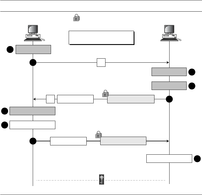
452 CHAPTER 15 KEY MANAGEMENT
The following shows the steps:
❏
After calculating R
1
, Alice sends R
1
to Bob (steps 1 and 2 in Figure 15.12).
❏ After calculating R
2
and the session key, Bob concatenates Alice’s ID, R
1
, and R
2
.
He then signs the result with his private key. Bob now sends R
2
, the signature, and
his own public-key certificate to Alice. The signature is encrypted with the session
key (steps 3, 4, and 5 in Figure 15.12).
❏
After calculating the session key, if Bob’s signature is verified, Alice concatenates
Bob’s ID, R
1
, and R
2
. She then signs the result with her own private key and sends it to
Bob. The signature is encrypted with the session key (steps 6, 7, and 8 in Figure 15.12).
❏
If Alice’s signature is verified, Bob keeps the session key (step 9 in Figure 15.12).
Security of Station-to-Station Protocol
The station-to-station protocol prevents man-in-the-middle attacks. After intercepting
R
1
, Eve cannot send her own R
2
to Alice and pretend it is coming from Bob because
Eve cannot forge the private key of Bob to create the signaturethe signature cannot
be verified with Bob’s public key defined in the certificate. In the same way, Eve cannot
forge Alice’s private key to sign the third message sent by Alice. The certificates, as we
will see in the next section, are trusted because they are issued by trusted authorities.
Figure 15.12 Station-to-station key agreement method
R
1
= g
x
mod p
R
2
= g
y
mod p
K = g
xy
mod p
The values of
p and g are public.
Shared Secret Key
R
1
First
message
K = (R
2
)
x
mod p
Verify Alice’s signature
Bob
Alice
1
3
Second
message
5
6
Verify Bob’s signature
7
K = (R
1
)
y
mod p
4
2
Third
message
8
9
Alice’s certificate
Signed by Alice’s private key
Sig
Alice
(Bob | R
1
| R
2
)
K
Encrypted with session key
K
Signed by Bob’s private key
R
2
Bob’s certificate
Sig
Bob
(Alice | R
1
| R
2
)
K

SECTION 15.4 PUBLIC-KEY DISTRIBUTION 453
15.4 PUBLIC-KEY DISTRIBUTION
In asymmetric-key cryptography, people do not need to know a symmetric shared key.
If Alice wants to send a message to Bob, she only needs to know Bob’s public key,
which is open to the public and available to everyone. If Bob needs to send a message
to Alice, he only needs to know Alice’s public key, which is also known to everyone. In
public-key cryptography, everyone shields a private key and advertises a public key.
Public keys, like secret keys, need to be distributed to be useful. Let us briefly dis-
cuss the way public keys can be distributed.
Public Announcement
The naive approach is to announce public keys publicly. Bob can put his public key on
his website or announce it in a local or national newspaper. When Alice needs to send a
confidential message to Bob, she can obtain Bob’s public key from his site or from the
newspaper, or even send a message to ask for it. Figure 15.13 shows the situation.
This approach, however, is not secure; it is subject to forgery. For example, Eve could
make such a public announcement. Before Bob can react, damage could be done. Eve can
fool Alice into sending her a message that is intended for Bob. Eve could also sign a docu-
ment with a corresponding forged private key and make everyone believe it was signed by
Bob. The approach is also vulnerable if Alice directly requests Bob’s public key. Eve can
intercept Bob’s response and substitute her own forged public key for Bob’s public key.
Trusted Center
A more secure approach is to have a trusted center retain a directory of public keys. The
directory, like the one used in a telephone system, is dynamically updated. Each user can
select a private and public key, keep the private key, and deliver the public key for inser-
tion into the directory. The center requires that each user register in the center and prove
his or her identity. The directory can be publicly advertised by the trusted center. The cen-
ter can also respond to any inquiry about a public key. Figure 15.14 shows the concept.
In public-key cryptography, everyone has access to everyone’s public key;
public keys are available to the public.
Figure 15.13 Announcing a public key
Bob
Public key

454 CHAPTER 15 KEY MANAGEMENT
Controlled Trusted Center
A higher level of security can be achieved if there are added controls on the distribution
of the public key. The public-key announcements can include a timestamp and be
signed by an authority to prevent interception and modification of the response. If Alice
needs to know Bob’s public key, she can send a request to the center including Bob’s
name and a timestamp. The center responds with Bob’s public key, the original request,
and the timestamp signed with the private key of the center. Alice uses the public key of
the center, known by all, to verify the timestamp. If the timestamp is verified, she
extracts Bob’s public key. Figure 15.15 shows one scenario.
Certification Authority
The previous approach can create a heavy load on the center if the number of requests
is large. The alternative is to create public-key certificates. Bob wants two things; he
wants people to know his public key, and he wants no one to accept a forged public key
as his. Bob can go to a certification authority (CA), a federal or state organization that
binds a public key to an entity and issues a certificate. The CA has a well-known public
key itself that cannot be forged. The CA checks Bob’s identification (using a picture ID
along with other proof). It then asks for Bob’s public key and writes it on the certificate.
To prevent the certificate itself from being forged, the CA signs the certificate with its
private key. Now Bob can upload the signed certificate. Anyone who wants Bob’s pub-
lic key downloads the signed certificate and uses the center’s public key to extract
Bob’s public key. Figure 15.16 shows the concept.
Figure 15.14 Trusted center
Trusted center
Directory
Alice
K
A
Bob
K
B

SECTION 15.4 PUBLIC-KEY DISTRIBUTION 455
Figure 15.15 Controlled trusted center
Figure 15.16 Certification authority
Alice
Need Bob's key, T
Trusted
center
Bob’s public key T: Timestamp
Need Bob's key, T,
Sig
center
(T)
Signed by center’s
private key
Directory
Alice
K
A
Bob
K
B
Bob
CA
CA: Certification authority
Bob’s
public key
Applying
Distributing
to public
Recording
Issuing
Signed with
CA’s private key
Bob’s certificate
Directory
Alice
K
A
Bob
K
B

456 CHAPTER 15 KEY MANAGEMENT
X.509
Although the use of a CA has solved the problem of public-key fraud, it has created a
side-effect. Each certificate may have a different format. If Alice wants to use a pro-
gram to automatically download different certificates and digests belonging to different
people, the program may not be able to do this. One certificate may have the public key
in one format and another in a different format. The public key may be on the first line
in one certificate, and on the third line in another. Anything that needs to be used uni-
versally must have a universal format.
To remove this side effect, the ITU has designed X.509, a recommendation that has
been accepted by the Internet with some changes. X.509 is a way to describe the certif-
icate in a structured way. It uses a well-known protocol called ASN.1 (Abstract Syntax
Notation 1) that defines fields familiar to C programmers.
Certificate
Figure 15.17 shows the format of a certificate.
A certificate has the following fields:
❏ Version number. This field defines the version of X.509 of the certificate. The ver-
sion number started at 0; the current version (third version) is 2.
❏ Serial number. This field defines a number assigned to each certificate. The value
is unique for each certificate issuer.
❏ Signature algorithm ID. This field identifies the algorithm used to sign the certif-
icate. Any parameter that is needed for the signature is also defined in this field.
❏ Issuer name. This field identifies the certification authority that issued the certifi-
cate. The name is normally a hierarchy of strings that defines a country, a state,
organization, department, and so on.
Figure 15.17 X.509 certificate format
Version number
Optional
Serial number
Signature algorithm ID
Issuer name
Validity period
Subject name
Subject public key
Signature
Hash algorithm ID + Cipher ID + Parameters
Issuer unique identifier
Subject unique identifier
Extensions
Hash
algorithm
Signature
algorithm
Signed with CA’s
private key
Digest
Signed
digest
SECTION 15.4 PUBLIC-KEY DISTRIBUTION 457
❏ Validity Period. This field defines the earliest time (not before) and the latest time
(not after) the certificate is valid.
❏ Subject name. This field defines the entity to which the public key belongs. It is
also a hierarchy of strings. Part of the field defines what is called the common
name, which is the actual name of the beholder of the key.
❏ Subject public key. This field defines the owner’s public key, the heart of the cer-
tificate. The field also defines the corresponding public-key algorithm (RSA, for
example) and its parameters.
❏ Issuer unique identifier. This optional field allows two issuers to have the same
issuer field value, if the issuer unique identifiers are different.
❏ Subject unique identifier. This optional field allows two different subjects to have
the same subject field value, if the subject unique identifiers are different.
❏ Extensions. This optional field allows issuers to add more private information to
the certificate.
❏ Signature. This field is made of three sections. The first section contains all
other fields in the certificate. The second section contains the digest of the first
section encrypted with the CA’s public key. The third section contains the algo-
rithm identifier used to create the second section.
Certificate Renewal
Each certificate has a period of validity. If there is no problem with the certificate, the
CA issues a new certificate before the old one expires. The process is like the renewal
of credit cards by a credit card company; the credit card holder normally receives a
renewed credit card before the one expires.
Certificate Revocation
In some cases a certificate must be revoked before its expiration. Here are some examples:
a. The user’s (subject’s) private key (corresponding to the public key listed in the cer-
tificate) might have been comprised.
b. The CA is no longer willing to certify the user. For example, the user’s certificate
relates to an organization that she no longer works for.
c. The CA’s private key, which can verify certificates, may have been compromised.
In this case, the CA needs to revoke all unexpired certificates.
The revocation is done by periodically issuing a certificate revocation list (CRL).
The list contains all revoked certificates that are not expired on the date the CRL is
issued. When a user wants to use a certificate, she first needs to check the directory of
the corresponding CA for the last certificate revocation list. Figure 15.18 shows the cer-
tificate revocation list.
A certificate revocation list has the following fields:
❏ Signature algorithm ID. This field is the same as the one in the certificate.
❏ Issuer name. This field is the same as the one in the certificate.
❏ This update date. This field defines when the list is released.
❏ Next update date. This field defines the next date when the new list will be released.

458 CHAPTER 15 KEY MANAGEMENT
❏ Revoked certificate. This is a repeated list of all unexpired certificates that have
been revoked. Each list contains two sections: user certificate serial number and
revocation date.
❏ Signature. This field is the same as the one in the certificate list.
Delta Revocation
To make revocation more efficient, the delta certificate revocation list (delta CRL) has
been introduced. A delta CRL is created and posted on the directory if there are
changes after this update date and next update date. For example, if CRLs are issued
every month, but there are revocations in between, the CA can create a delta CRL when
there is a change during the month. However, a delta CRL contains only the changes
made after the last CRL.
Public-Key Infrastructures (PKI)
Public-Key Infrastructure (PKI) is a model for creating, distributing, and revoking
certificates based on the X.509. The Internet Engineering Task Force (see Appendix B)
has created the Public-Key Infrastructure X.509 (PKIX).
Duties
Several duties have been defined for a PKI. The most important ones are shown in
Figure 15.19.
❏ Certificates’ issuing, renewal, and revocation. These are duties defined in the
X.509. Because the PKIX is based on X.509, it needs to handle all duties related to
certificates.
❏ Keys’ storage and update. A PKI should be a storage place for private keys of
those members that need to hold their private keys somewhere safe. In addition, a
PKI is responsible for updating these keys on members’ demands.
Figure 15.18 Certificate revocation format
Signature algorithm ID
Issuer name
This update date
Next update date
Revoked certificate
Signature
Hash algorithm ID + Cipher ID + Parameters
Revoked certificate
Hash
algorithm
Signature
algorithm
Signed with CA’s
private key
Digest
Signed
digest

SECTION 15.4 PUBLIC-KEY DISTRIBUTION 459
❏ Providing services to other protocols. As we see will in the next few chapters,
some Internet security protocols, such as IPSec and TLS, are relying on the ser-
vices by a PKI.
❏ Providing access control. A PKI can provide different levels of access to the infor-
mation stored in its database. For example, an organization PKI may provide access
to the whole database for the top management, but limited access for employees.
Trust Model
It is not possible to have just one CA issuing all certificates for all users in the world.
There should be many CAs, each responsible for creating, storing, issuing, and revok-
ing a limited number of certificates. The trust model defines rules that specify how a
user can verify a certificate received from a CA.
Hierarchical Model In this model, there is a tree-type structure with a root CA. The
root CA has a self-signed, self-issued certificate; it needs to be trusted by other CAs and
users for the system to work. Figure 15.20 shows a trust model of this kind with three
hierarchical levels. The number of levels can be more than three in a real situation.
Figure 15.19 Some duties of a PKI
Figure 15.20 PKI hierarchical model
Certificates’ issuing,
renewal, and revocation
Keys’ storage
and update
Providing services
to other protocols
Providing
access control
PKI’s
duties
CA1 CA2 CA3
User1 User2 User3
CA
User4 User5
User6 User7 User8
X Y
means X has signed a certificate for Y

460 CHAPTER 15 KEY MANAGEMENT
The figure shows that the CA (the root) has signed certificates for CA1, CA2, and
CA3; CA1 has signed certificates for User1, User2, and User3; and so on. PKI uses the
following notation to mean the certificate issued by authority X for entity Y.
Example 15.3
Show how User1, knowing only the public key of the CA (the root), can obtain a verified copy of
User3’s public key.
Solution
User3 sends a chain of certificates, CA<<CA1>> and CA1<<User3>>, to User1.
a. User1 validates CA<<CA1>> using the public key of CA.
b. User1 extracts the public key of CA1 from CA<<CA1>>.
c. User1 validates CA1<<User3>> using the public key of CA1.
d. User1 extracts the public key of User 3 from CA1<<User3>>.
Example 15.4
Some Web browsers, such as Netscape and Internet Explorer, include a set of certificates from
independent roots without a single, high-level, authority to certify each root. One can find the
list of these roots in the Internet Explorer at Tools/Internet Options/Contents/Certificate/
Trusted roots (using pull-down menu). The user then can choose any of this root and view the
certificate.
Mesh Model The hierarchical model may work for an organization or a small com-
munity. A larger community may need several hierarchical structures connected
together. One method is to use a mesh model to connect the roots together. In this
model, each root is connected to every other root, as shown in Figure 15.21.
Figure 15.21 shows that the mesh structure connects only roots together; each root
has its own hierarchical structure, shown by a triangle. The certifications between the
roots are cross-certificates; each root certifies all other roots, which means there are N
(N − 1) certificates. In Figure 15.21, there are 4 nodes, so we need 4 × 3 = 12 certifi-
cates. Note that each double-arrow line represents two certificates.
Example 15.5
Alice is under the authority Root1; Bob is under the authority Root4. Show how Alice can obtain
Bob’s verified public key.
Solution
Bob sends a chain of certificates from Root4 to Bob. Alice looks at the directory of Root1 to find
Root1<<Root1>> and Root1<< Root4>> certificates. Using the process shown in Figure 15.21,
Alice can verify Bob’s public key.
Web of Trust This model is used in Pretty Good Privacy, a security service for elec-
tronic mail discussed in Chapter 16.
X<<Y>>

SECTION 15.5 RECOMMENDED READING 461
15.5 RECOMMENDED READING
The following books and websites give more details about subjects discussed in this
chapter. The items enclosed in brackets refer to the reference list at the end of the
book.
Books
For further discussion of symmetric-key and asymmetric-key management, see [Sti06],
[KPS02], [Sta06], [Rhe03], and [PHS03].
WebSites
The following websites give more information about topics discussed in this chapter.
Figure 15.21
Mesh model
http://en.wikipedia.org/wiki/Needham-Schroeder
http://en.wikipedia.org/wiki/Otway-Rees
http://en.wikipedia.org/wiki/Kerberos_%28protocol%29
en.wikipedia.org/wiki/Diffie-Hellman
www.ietf.org/rfc/rfc2631.txt
Root1 Root2
Root3 Root4
means X and Y have signed a certificate for each other.
X Y

462 CHAPTER 15 KEY MANAGEMENT
15.6 KEY TERMS AND CONCEPTS
15.7 SUMMARY
❏ Symmetric-key cryptography needs a shared secret key between two parties. If N
people need to communicate with each other, N(N − 1)/2 keys are needed. The
number of keys is not the only problem; the distribution of keys is another.
❏ A practical solution is the use of a trusted third party, referred to as a key-distribution
center (KDC). A KDC can create a session (temporary) key between Alice and
Bob using their keys with the center. The keys of Alice and Bob are used to authen-
ticate Alice and Bob to the center.
❏ Several different approaches have been proposed to create the session key using
ideas discussed in Chapter 14 for entity authentication. Two of the most elegant
ones are Needham-Schroeder protocol, which is a foundation for many other
protocols, and Otway-Rees Protocol.
❏ Kerberos is both an authentication protocol and a KDC. Several systems, including
Windows 2000, use Kerberos. Three servers are involved in the Kerberos protocol:
an authentication server (AS), a ticket-granting server (TGS), and a real (data)
server.
❏ Alice and Bob can create a session key between themselves without using a KDC.
This method of session-key creation is referred to as the symmetric-key agreement.
We discussed two methods: Diffie-Hellman and station-to-station. The first is sus-
ceptible to the man-in-the-middle attack; the second is not.
❏ Public keys, like secret keys, need to be distributed to be useful. Certificate
authorities (CAs) provide certificates as proof of the ownership of public keys.
X.509 is a recommendation that defines the structure of certificates issued
by CAs.
❏ Public Key Infrastructure (PKI) is a model for creating, distributing, and revoking
certificates based on the X.509. The Internet Engineering Task Force has created
the Public Key Infrastructure X.509 (PKIX). The duties of a PKI include certifi-
cate issuing, private key storage, services to other protocols, and access control.
authentication server (AS) public-key certificate
bucket brigade attack public-key infrastructure (PKI)
certification authority (CA) session key
Diffie-Hellman protocol station-to-station protocol
Kerberos ticket
key-distribution center (KDC) ticket-granting server (TGS)
man-in-the-middle attack trust model
Needham-Schroeder protocol X.509
Otway-Rees protocol

SECTION 15.8 PRACTICE SET 463
A PKI also defines trust models, the relationship between certificate authorities.
The three trust models mentioned in this chapter are hierarchical, mesh, and web
of trust.
15.8 PRACTICE SET
Review Questions
1. List the duties of a KDC.
2. Define a session key and show how a KDC can create a session key between Alice
and Bob.
3. Define Kerberos and name its servers. Briefly explain the duties of each server.
4. Define the Diffie-Hellman protocol and its purpose.
5. Define the man-in-the-middle attack.
6. Define the station-to-station protocol and mention its purpose.
7. Define a certification authority (CA) and its relation to public-key cryptography.
8. Define the X.509 recommendation and state its purpose.
9. List the duties of a PKI.
10. Define a trust model and mention some variations of this model discussed in this
chapter.
Exercises
11. In Figure 15.4, what happens if the ticket for Bob is not encrypted in step 2 with
K
B
, but is encrypted instead by K
AB
in step 3?
12. Why is there a need for two nonces in the Needham-Schroeder protocol?
13. In the Needham-Schroeder protocol, how is Alice authenticated by the KDC? How
is Bob authenticated by the KDC? How is the KDC authenticated to Alice? How is
the KDC authenticated to Bob? How is Alice authenticated to Bob? How is Bob
authenticated to Alice?
14. Can you explain why in the Needham-Schroeder protocol, Alice is the party that is
in contact with the KDC, but in the Otway-Rees protocol, Bob is the party that is in
contact with the KDC?
15. There are two nonces (R
A
and R
B
) in the Needham-Schroeder protocol, but three
nonces (R
A
, R
B
, and R) in the Otway-Rees protocol. Can you explain why there is
a need for one extra nonce, R
2
, in the first protocol?
16. Why do you think we need only one timestamp in Kerberos instead of two nonces
as in Needham-Schroeder or three nonces as in Otway-Rees?
17. In the Diffie-Hellman protocol, g = 7, p = 23, x = 3, and y = 5.
a. What is the value of the symmetric key?
b. What is the value of R
1
and R
2
?
464 CHAPTER 15 KEY MANAGEMENT
18. In the Diffie-Hellman protocol, what happens if x and y have the same value, that
is, Alice and Bob have accidentally chosen the same number? Are R
1
and R
2
the
same? Do the session keys calculated by Alice and Bob have the same value? Use
an example to prove your claims.
19. In a trivial (not secure) Diffie-Hellman key exchange, p = 53. Find an appropriate
value for g.
20. In station-to-station protocol, show that if the identity of the receiver is removed
from the signature, the protocol becomes vulnerable to the man-in-the-middle
attack.
21. Discuss the trustworthiness of root certificates provided by browsers.

467
CHAPTER 16
Security at the Application Layer:
PGP and S/MIME
Objectives
This chapter has several objectives:
❏ To explain the general structure of an e-mail application program
❏ To discuss how PGP can provide security services for e-mail
❏ To discuss how S/MIME can provide security services for e-mail
❏ To define trust mechanism in both PGP and S/MIME
❏ To show the structure of messages exchanged in PGP and S/MIME
This chapter discusses two protocols providing security services for
e-mails: Pretty Good Privacy (PGP) and Secure/Multipurpose Internet
Mail Extension (S/MIME). Understanding each of these protocols
requires the general understanding of the e-mail system. We first discuss
the structure of electronic mail. We then show how PGP and S/MIME
can add security services to this structure. Emphasis is on how PGP and
S/MIME can exchange cryptographic algorithms, secret keys, and certif-
icates without establishing a session between Alice and Bob.
16.1 E-MAIL
Let us first discuss the electronic mail (e-mail) system in general.
E-mail Architecture
Figure 16.1 shows the most common scenario in a one-way e-mail exchange. Assume
that Alice is working in an organization that runs an e-mail server; every employee
is connected to the e-mail server through a LAN. Or alternatively, Alice could

468 CHAPTER 16 SECURITY AT THE APPLICATION LAYER: PGP AND S/MIME
be connected to the e-mail server of an ISP through a WAN (telephone line or cable
line). Bob is also in one of the above two situations.
The administrator of the e-mail server at Alice’s site has created a queuing system
that sends e-mail to the Internet one by one. The administrator of the e-mail server at
Bob’s site has created a mailbox for every user connected to the server; the mailbox
holds the received messages until they are retrieved by the recipient.
When Alice needs to send a message to Bob, she invokes a user agent (UA) program
to prepare the message. She then uses another program, a message transfer agent (MTA),
to send the message to the mail server at her site. Note that the MTA is a client/server pro-
gram with the client installed at Alice’s computer and the server installed at the mail server.
The message received at the mail server at Alice’s site is queued with all other
messages; each goes to its corresponding destination. In Alice’s case, her message goes
to the mail server at Bob’s site. A client/server MTA is responsible for the e-mail transfer
between the two servers. When the message arrives at the destination mail server, it is
stored in Bob’s mailbox, a special file that holds the message until it is retrieved by Bob.
When Bob needs to retrieve his messages, including the one sent by Alice, he
invokes another program, which we call a message access agent (MAA). The MAA is
also designed as a client/server program with the client installed at Bob’s computer and
the server installed at the mail server.
There are several important points about the architecture of the e-mail system.
a. The sending of an e-mail from Alice to Bob is a store-retrieve activity. Alice can
send an e-mail today; Bob, being busy, may check his e-mail three days later. Dur-
ing this time, the e-mail is stored in Bob’s mailbox until it is retrieved.
b. The main communication between Alice and Bob is through two application pro-
grams: the MTA client at Alice’s computer and the MAA client at Bob’s computer.
c. The MTA client program is a push program; the client pushes the message when
Alice needs to send it. The MAA client program is a pull program; the client pulls
the messages when Bob is ready to retrieve his e-mail.
Figure 16.1
E-mail architecture
Mail server
LAN or WAN
LAN or WAN
Mail server
Internet
MTA
server
MTA
server
MAA
server
MTA
client
Bob
UA: User agent
MTA: Message transfer agent
MAA: Message access agent
MAA
client
UA
Alice
UA
MTA
client

SECTION 16.1 E-MAIL 469
d. Alice and Bob cannot directly communicate using an MTA client at the sender site
and an MTA server at the receiver site. This requires that the MTA server be running
all the time, because Bob does not know when a message will arrive. This is not
practical, because Bob probably turns off his computer when he does not need it.
E-mail Security
Sending an e-mail is a one-time activity. The nature of this activity is different from
those we will see in the next two chapters. In IPSec or SSL, we assume that the two
parties create a session between themselves and exchange data in both directions. In
e-mail, there is no session. Alice and Bob cannot create a session. Alice sends a mes-
sage to Bob; sometime later, Bob reads the message and may or may not send a reply.
We discuss the security of a unidirectional message because what Alice sends to Bob is
totally independent from what Bob sends to Alice.
Cryptographic Algorithms
If e-mail is a one-time activity, how can the sender and receiver agree on a crypto-
graphic algorithm to use for e-mail security? If there is no session and no handshaking
to negotiate the algorithms for encryption/decryption and hashing, how can the receiver
know which algorithm the sender has chosen for each purpose?
One solution is for the underlying protocol to select one algorithm for each crypto-
graphic operation and to force Alice to use only those algorithms. This solution is very
restrictive and limits the capabilities of the two parties.
A better solution is for the underlying protocol to define a set of algorithms for
each operation that the user used in his/her system. Alice includes the name (or identifi-
ers) of the algorithms she has used in the e-mail. For example, Alice can choose triple
DES for encryption/decryption and MD5 for hashing. When Alice sends a message to
Bob, she includes the corresponding identifiers for triple DES and MD5 in her mes-
sage. Bob receives the message and extracts the identifiers first. He then knows which
algorithm to use for decryption and which one for hashing.
Cryptographic Secrets
The same problem for the cryptographic algorithms applies to the cryptographic secrets
(keys). If there is no negotiation, how can the two parties establish secrets between
themselves? Alice and Bob could use asymmetric-key algorithms for authentication
and encryption, which do not require the establishment of a symmetric key. However,
as we have discussed, the use of asymmetric-key algorithms is very inefficient for the
encryption/decryption of a long message.
Most e-mail security protocols today require that encryption/decryption be done
using a symmetric-key algorithm and a one-time secret key sent with the message.
Alice can create a secret key and send it with the message she sends to Bob. To protect
In e-mail security, the sender of the message needs to include the name or identifiers
of the algorithms used in the message.

470 CHAPTER 16 SECURITY AT THE APPLICATION LAYER: PGP AND S/MIME
the secret key from interception by Eve, the secret key is encrypted with Bob’s public
key. In other words, the secret key itself is encrypted.
Certificates
One more issue needs to be considered before we discuss any e-mail security protocol
in particular. It is obvious that some public-key algorithms must be used for e-mail
security. For example, we need to encrypt the secret key or sign the message. To
encrypt the secret key, Alice needs Bob’s public key; to verify a signed message, Bob
needs Alice’s public key. So, for sending a small authenticated and confidential mes-
sage, two public keys are needed. How can Alice be assured of Bob’s public key, and
how can Bob be assured of Alice’s public key? Each e-mail security protocol has a dif-
ferent method of certifying keys.
16.2 PGP
The first protocol discussed in this chapter is called Pretty Good Privacy (PGP). PGP
was invented by Phil Zimmermann to provide e-mail with privacy, integrity, and
authentication. PGP can be used to create a secure e-mail message or to store a file
securely for future retrieval.
Scenarios
Let us first discuss the general idea of PGP, moving from a simple scenario to a com-
plex one. We use the term “Data” to show the message or file prior to processing.
Plaintext
The simplest scenario is to send the e-mail message (or store the file) in plaintext as
shown in Figure 16.2. There is no message integrity or confidentiality in this scenario.
Alice, the sender, composes a message and sends it to Bob, the receiver. The message is
stored in Bob’s mailbox until it is retrieved by him.
In e-mail security, the encryption/decryption is done using a symmetric-key algorithm,
but the secret key to decrypt the message is encrypted with the public key of the
receiver and is sent with the message.
Figure 16.2
A plaintext message
Alice
Data
Bob

SECTION 16.2 PGP 471
Message Integrity
Probably the next improvement is to let Alice sign the message. Alice creates a digest
of the message and signs it with her private key. When Bob receives the message, he
verifies the message by using Alice’s public key. Two keys are needed for this scenario.
Alice needs to know her private key; Bob needs to know Alice’s public key. Figure 16.3
shows the situation.
Compression
A further improvement is to compress the message to make the packet more compact.
This improvement has no security benefit, but it eases the traffic. Figure 16.4 shows the
new scenario.
Confidentiality with One-Time Session Key
As we discussed before, confidentiality in an e-mail system can be achieved using
conventional encryption with a one-time session key. Alice can create a session key, use
the session key to encrypt the message and the digest, and send the key itself with the
message. However, to protect the session key, Alice encrypts it with Bob’s public key.
Figure 16.5 shows the situation.
When Bob receives the packet, he first decrypts the key, using his private key to
remove the key. He then uses the session key to decrypt the rest of the message. After
decompressing the rest of the message, Bob creates a digest of the message and
checks to see if it is equal to the digest sent by Alice. If it is, then the message is
authentic.
Figure 16.3
An authenticated message
Figure 16.4
A compressed message
Alice Bob
Aliceís
public key
Alice’s
private key
Digitally signed with
Alice’s private key
A
DigestData
A
Alice Bob
Alice’s
public key
Alice’s
private key
Digitally signed with
Alice’s private key
A
Digest
Data
(compressed)
A

472 CHAPTER 16 SECURITY AT THE APPLICATION LAYER: PGP AND S/MIME
Code Conversion
Another service provided by PGP is code conversion. Most e-mail systems allow the
message to consist of only ASCII characters. To translate other characters not in the
ASCII set, PGP uses Radix-64 conversion. Each character to be sent (after encryption)
is converted to Radix-64 code, which is discussed later in the chapter.
Segmentation
PGP allows segmentation of the message after it has been converted to Radix-64 to make
each transmitted unit the uniform size as allowed by the underlying e-mail protocol.
Key Rings
In all previous scenarios, we assumed that Alice needs to send a message only to Bob.
That is not always the case. Alice may need to send messages to many people; she
needs key rings. In this case, Alice needs a ring of public keys, with a key belonging to
each person with whom Alice needs to correspond (send or receive messages). In addi-
tion, the PGP designers specified a ring of private/public keys. One reason is that Alice
may wish to change her pair of keys from time to time. Another reason is that Alice
may need to correspond with different groups of people (friends, colleagues, and so
on). Alice may wish to use a different key pair for each group. Therefore, each user
needs to have two sets of rings: a ring of private/public keys and a ring of public keys of
other people. Figure 16.6 shows a community of four people, each having a ring of
pairs of private/public keys and, at the same time, a ring of public keys belonging to
other people in the community.
Alice, for example, has several pairs of private/public keys belonging to her and
public keys belonging to other people. Note that everyone can have more than one pub-
lic key. Two cases may arise.
1. Alice needs to send a message to another person in the community.
a. She uses her private key to sign the digest.
b. She uses the receiver’s public key to encrypt a newly created session key.
c. She encrypts the message and signed digest with the session key created.
Figure 16.5
A confidential message
Alice
Bob
Alice’s
public key
Alice’s
private key
Bob’s
private key
Bob’s
public key
B
Digest
Message
(compressed)
A
Shared
session key
Digitally signed with Alice’s private key
A
Encrypted with Bob’s public key
Encrypted with shared session key
B

SECTION 16.2 PGP 473
2. Alice receives a message from another person in the community.
a. She uses her private key to decrypt the session key.
b. She uses the session key to decrypt the message and digest.
c. She uses her public key to verify the digest.
PGP Algorithms
The following algorithms are used in PGP.
Public-Key Algorithms The public-key algorithms that are used for signing the digests
or encrypting the messages are listed in Table 16.1.
Symmetric-Key Algorithms The symmetric-key algorithms that are used for con-
ventional encrypting are shown in Table 16.2.
Figure 16.6
Key rings in PGP
Table 16.1
Public-key algorithms
ID Description
1 RSA (encryption or signing)
2 RSA (for encryption only)
3 RSA (for signing only)
16 ElGamal (encryption only)
17 DSS
18 Reserved for elliptic curve
19 Reserved for ECDSA
20 ElGamal (for encryption or signing)
21 Reserved for Diffie-Hellman
100−110 Private algorithms
Alice’s rings
Ted’s rings John’s rings
Bob’s rings
Private
ring
Private
ring
Private
ring
Private
ring
Public
ring
Public
ring
Public
ring
Public
ring

474 CHAPTER 16 SECURITY AT THE APPLICATION LAYER: PGP AND S/MIME
Hash Algorithms The hash algorithms that are used for creating hashes in PGP are
shown in Table 16.3.
Compression Algorithms The compression algorithms that are used for compress-
ing text are shown in Table 16.4.
Table 16.2 Symmetric-key algorithms
ID Description
0 No Encryption
1 IDEA
2 Triple DES
3 CAST-128
4 Blowfish
5 SAFER-SK128
6 Reserved for DES/SK
7 Reserved for AES-128
8 Reserved for AES-192
9 Reserved for AES-256
100−110 Private algorithms
Table 16.3
Hash Algorithms
ID Description
1 MD5
2 SHA-1
3 RIPE-MD/160
4 Reserved for double-width SHA
5 MD2
6 TIGER/192
7 Reserved for HAVAL
100−110 Private algorithms
Table 16.4
Compression methods
ID Description
0 Uncompressed
1 ZIP
2 ZLIP
100−110 Private methods

SECTION 16.2 PGP 475
PGP Certificates
PGP, like other protocols we have seen so far, uses certificates to authenticate public
keys. However, the process is totally different.
X.509 Certificates
Protocols that use X.509 certificates depend on the hierarchical structure of the trust.
There is a predefined chain of trust from the root to any certificate. Every user fully
trusts the authority of the CA at the root level (prerequisite). The root issues certificates
for the CAs at the second level, a second level CA issues a certificate for the third level,
and so on. Every party that needs to be trusted presents a certificate from some CA in
the tree. If Alice does not trust the certificate issuer for Bob, she can appeal to a higher-
level authority up to the root (which must be trusted for the system to work). In other
words, there is one single path from a fully trusted CA to a certificate.
PGP Certificates
In PGP, there is no need for CAs; anyone in the ring can sign a certificate for anyone
else in the ring. Bob can sign a certificate for Ted, John, Anne, and so on. There is no
hierarchy of trust in PGP; there is no tree. The lack of hierarchical structure may result
in the fact that Ted may have one certificate from Bob and another certificate from Liz.
If Alice wants to follow the line of certificates for Ted, there are two paths: one starts
from Bob and one starts from Liz. An interesting point is that Alice may fully trust Bob,
but only partially trust Liz. There can be multiple paths in the line of trust from a fully
or partially trusted authority to a certificate. In PGP, the issuer of a certificate is usually
called an introducer.
Trusts and Legitimacy
The entire operation of PGP is based on introducer trust, the certificate trust, and the
legitimacy of the public keys.
Introducer Trust Levels With the lack of a central authority, it is obvious that the
ring cannot be very large if every user in the PGP ring of users has to fully trust every-
one else. (Even in real life we cannot fully trust everyone that we know.) To solve this
problem, PGP allows different levels of trust. The number of levels is mostly imple-
mentation dependent, but for simplicity, let us assign three levels of trust to any intro-
ducer: none, partial, and full. The introducer trust level specifies the trust levels issued
by the introducer for other people in the ring. For example, Alice may fully trust Bob,
partially trust Anne, and not trust John at all. There is no mechanism in PGP to deter-
mine how to make a decision about the trustworthiness of the introducer; it is up to the
user to make this decision.
In X.509, there is a single path from the fully trusted authority to any certificate.
In PGP, there can be multiple paths from fully or partially trusted authorities to any subject.
476 CHAPTER 16 SECURITY AT THE APPLICATION LAYER: PGP AND S/MIME
Certificate Trust Levels When Alice receives a certificate from an introducer, she
stores the certificate under the name of the subject (certified entity). She assigns a level
of trust to this certificate. The certificate trust level is normally the same as the intro-
ducer trust level that issued the certificate. Assume that Alice fully trusts Bob, partially
trusts Anne and Janette, and has no trust in John. The following scenarios can happen.
1. Bob issues two certificates, one for Linda (with public key K1) and one for Lesley
(with public key K2). Alice stores the public key and certificate for Linda under
Linda’s name and assigns a full level of trust to this certificate. Alice also stores the
certificate and public key for Lesley under Lesley’s name and assigns a full level of
trust to this certificate.
2. Anne issues a certificate for John (with public key K3). Alice stores this certificate
and public key under John’s name, but assigns a partial level for this certificate.
3. Janette issues two certificates, one for John (with public key K3) and one for Lee
(with public key K4). Alice stores John’s certificate under his name and Lee’s certifi-
cate under his name, each with a partial level of trust. Note that John now has two
certificates, one from Anne and one from Janette, each with a partial level of trust.
4. John issues a certificate for Liz. Alice can discard or keep this certificate with a sig-
nature trust of none.
Key Legitimacy The purpose of using introducer and certificate trusts is to deter-
mine the legitimacy of a public key. Alice needs to know how legitimate the public keys
of Bob, John, Liz, Anne, and so on are. PGP defines a very clear procedure for deter-
mining key legitimacy. The level of the key legitimacy for a user is the weighted trust
levels of that user. For example, suppose we assign the following weights to certificate
trust levels:
1. A weight of 0 to a nontrusted certificate
2. A weight of 1/2 to a certificate with partial trust
3. A weight of 1 to a certificate with full trust
Then to fully trust an entity, Alice needs one fully trusted certificate or two partially
trusted certificates for that entity. For example, Alice can use John’s public key in the
previous scenario because both Anne and Janette have issued a certificate for John,
each with a certificate trust level of 1/2. Note that the legitimacy of a public key belong-
ing to an entity does not have anything to do with the trust level of that person.
Although Bob can use John’s public key to send a message to him, Alice cannot accept
any certificate issued by John because, for Alice, John has a trust level of none.
Starting the Ring
You might have realized a problem with the above discussion. What if nobody sends
a certificate for a fully or partially trusted entity? For example, how can the legiti-
macy of Bob’s public key be determined if no one has sent a certificate for Bob? In
PGP, the key legitimacy of a trusted or partially trusted entity can be also determined
by other methods.
1. Alice can physically obtain Bob’s public key. For example, Alice and Bob can meet
personally and exchange a public key written on a piece of paper or to a disk.

SECTION 16.2 PGP 477
2. If Bob’s voice is recognizable to Alice, Alice can call him and obtain his public key
on the phone.
3. A better solution proposed by PGP is for Bob to send his public key to Alice by
e-mail. Both Alice and Bob make a 16-byte MD5 (or 20-byte SHA-1) digest from
the key. The digest is normally displayed as eight groups of 4 digits (or ten groups
of 4 digits) in hexadecimal and is called a fingerprint. Alice can then call Bob
and verify the fingerprint on the phone. If the key is altered or changed during
the e-mail transmission, the two fingerprints do not match. To make it even more
convenient, PGP has created a list of words, each representing a 4-digit combina-
tion. When Alice calls Bob, Bob can pronounce the eight words (or ten words) for
Alice. The words are carefully chosen by PGP to avoid those similar in pronuncia-
tion; for example, if sword is in the list, word is not.
4. In PGP, nothing prevents Alice from getting Bob’s public key from a CA in a sepa-
rate procedure. She can then insert the public key in the public key ring.
Key Ring Tables
Each user, such as Alice, keeps track of two key rings: one private-key ring and one
public key ring. PGP defines a structure for each of these key rings in the form of a table.
Private Key Ring Table Figure 16.7 shows the format of a private key ring table.
❏
User ID. The user ID is usually the e-mail address of the user. However, the user
may designate a unique e-mail address or alias for each key pair. The table lists the
user ID associated with each pair.
❏
Key ID. This column uniquely defines a public key among the user’s public keys.
In PGP, the key ID for each pair is the first (least significant) 64 bits of the public
key. In other words, the key ID is calculated as (key mod 2
64
). The key ID is
needed for the operation of PGP because Bob may have several public keys
belonging to Alice in his public key ring. When he receives a message from Alice,
Bob must know which key ID to use to verify the message. The key ID, which is
sent with the message, as we will see shortly, enables Bob to use a specific public
key for Alice from his public ring. You might ask why the entire public key is not
sent. The answer is that in public-key cryptography, the size of the public key may
be very long. Sending just 8 bytes reduces the size of the message.
❏
Public Key. This column just lists the public key belonging to a particular private
key/public key pair.
Figure 16.7
Format of private key ring table
Timestamp
Encrypted
private key
Public
key
Key
ID
User
ID
Private ring

478 CHAPTER 16 SECURITY AT THE APPLICATION LAYER: PGP AND S/MIME
❏
Encrypted Private Key. This column shows the encrypted value of the private
key in the private key/public key pair. Although Alice is the only person access-
ing her private ring, PGP saves only the encrypted version of the private key. We
will see later how the private key is encrypted and decrypted.
❏
Timestamp. This column holds the date and time of the key pair creation. It
helps the user decide when to purge old pairs and when to create new ones.
Example 16.1
Let us show a private key ring table for Alice. We assume that Alice has only two user IDs,
keys, one for each user ID. Table 16.5 shows the private key ring table for Alice.
Note that although the values of key ID, public key, and private key are shown in hexadeci-
mal, and ddmmyy-time format is used for the timestamp, these formats are only for presentation
and may be different in an actual implementation.
Public Key Ring Table Figure 16.8 shows the format of a public key ring table.
❏
User ID. As in the private key ring table, the user ID is usually the e-mail address
of the entity.
❏
Key ID. As in the private key ring table, the key ID is the first (least significant)
64 bits of the public key.
❏ Public Key. This is the public key of the entity.
❏
Producer Trust. This column defines the producer level of trust. In most imple-
mentations, it can only be of one of three values: none, partial, or full.
❏
Certificate(s). This column holds the certificate or certificates signed by other
entities for this entity. A user ID may have more than one certificate.
Table 16.5
Private key ring table for Example 1
User ID Key ID Public Key
Encrypted
Private Key
Timestamp
Figure 16.8 Format of a public key ring table
Public ring
Timestamp
Key
Legitimacy
Certificate
trust(s)
Certificate(s)
Producer
trust
Public
key
User
ID
Key
ID

SECTION 16.2 PGP 479
❏ Certificate Trust(s). This column represents the certificate trust or trusts. If Anne
sends a certificate for John, PGP searches the row entry for Anne, finds the value of
the producer trust for Anne, copies that value, and inserts it in the certificate trust
field in the entry for John.
❏ Key Legitimacy. This value is calculated by PGP based on the value of the certifi-
cate trust and the predefined weight for each certificate trust.
❏ Timestamp. This column holds the date and time of the column creation.
Example 16.2
A series of steps will show how a public key ring table is formed for Alice.
1. Start with one row, Alice herself, as shown in Table 16.6. Use N (none), P (partial), and F
(full) for the levels of trust. For simplicity, also assume that everyone (including Alice) has
only one user ID.
Note that, based on this table, we assume that Alice has issued a certificate for herself (implic-
itly). Alice of course trusts herself fully. The producer level of trust is also full and so is the key
legitimacy. Although Alice never uses this first row, it is needed for the operation of PGP.
2. Now Alice adds Bob to the table. Alice fully trusts Bob, but to obtain his public key, she asks
Bob to send the public key by e-mail as well as his fingerprint. Alice then calls Bob to check
the fingerprint. Table 16.7 shows this new event.
Note that the value of the producer trust is full for Bob because Alice fully trusts Bob. The
value of the certificate field is empty, which shows that this key has been received indirectly,
and not by a certificate.
3. Now Alice adds Ted to the table. Ted is fully trusted. However, for this particular user,
Alice does not have to call Ted. Instead, Bob, who knows Ted’s public key, sends Alice a
certificate that includes Ted’s public key, as shown in Table 16.8.
Table 16.6 Example 2, starting table
User
ID
Key
ID
Public
key
Prod.
trust
Certificate
Cert.
trust
Key
legit.
Time-
stamp
Alice... AB... AB....... F
F ........
Table 16.7 Example 2, after Bob is added to the table
User
ID
Key
ID
Public
key
Prod.
trust
Certificate
Cert.
trust
Key
legit.
Time-
stamp
Alice... AB... AB........ F
F ........
Bob... 12... 12........ F
F ........
Table 16.8 Example 2, after Ted is added to the table
User
ID
Key
ID
Public
key
Prod.
trust
Certificate
Cert.
trust
Key
legit.
Time-
stamp
Alice... AB... AB........ F
F ........
Bob... 12... 12........ F
F ........
Ted... 48... 48........ F Bob’s F F ........

480 CHAPTER 16 SECURITY AT THE APPLICATION LAYER: PGP AND S/MIME
Note that the value of certificate field shows that the certificate was received from Bob.
The value of the certificate trust is copied by PGP from Bob’s producer trust field. The
value of the key legitimacy field is the value of the certificate trust multiplied by 1 (the
weight).
4. Now Alice adds Anne to the list. Alice partially trusts Anne, but Bob, who is fully trusted,
sends a certificate for Anne. Table 16.9 shows the new event.
Note that the producer trust value for Anne is partial, but the certificate trust and key legiti-
macy is full.
5. Now Anne introduces John, who is not trusted by Alice. Table 16.10 shows the new
event.
Note that PGP has copied the value of Anne’s producer trust (P) to the certificate trust
field for John. The value of the key legitimacy field for John is 1/2 (P) at this moment,
which means that Alice must not use John’s key until it changes to 1 (F).
6. Now Janette, who is unknown to Alice, sends a certificate for Lee. Alice totally ignores this
certificate because she does not know Janette.
7. Now Ted sends a certificate for John (John, who is trusted by Ted, has probably asked Ted to
send this certificate). Alice looks at the table and finds John’s user ID with the corresponding
key ID and public key. Alice does not add another row to the table; she just modifies the
table as shown in Table 16.11.
Because John has two certificates in Alice’s table and his key legitimacy value is 1, Alice
can use his key. But John is still untrustworthy. Note that Alice can continue to add entries to
the table.
Table 16.9 Example 2, after Anne is added to the table
User
ID
Key
ID
Public
key
Prod.
trust
Certificate
Cert.
trust
Key
legit.
Time-
stamp
Alice... AB... AB........ F
F ........
Bob... 12... 12........ F
F ........
Ted... 48... 48........ F
Bob’s F F ........
Anne... 71... 71........ P
Bob’s F F ........
Table 16.10 Example 2, after John is added to the table
User
ID
Key
ID
Public
key
Prod.
Trust
Certificate
Cert.
trust
Key
legit.
Time-
stamp
Alice... AB... AB........ F
F ........
Bob... 12... 12........ F
F ........
Ted... 48... 48........ F
Bob’s F F ........
Anne... 71... 71........ P
Bob’s F F ........
John... 31... 31........ N
Anne’s P P ........

SECTION 16.2 PGP 481
Trust Model in PGP
As Zimmermann has proposed, we can create a trust model for any user in a ring with the
user as the center of activity. Such a model can look like the one shown in Figure 16.9.
The figure shows the trust model for Alice at some moment. The diagram may change
with any changes in the public key ring table.
Let us elaborate on the figure. Figure 16.9 shows that there are three entities in
Alice’s ring with full trust (Alice herself, Bob, and Ted). The figure also shows three
entities with partial trust (Anne, Mark, and Bruce). There are also six entities with no
trust. Nine entities have a legitimate key. Alice can encrypt a message to any one of
these entities or verify a signature received from one of these entities (Alice’s key is
never used in this model). There are also three entities that do not have any legitimate
keys with Alice.
Table 16.11
Example 2, after one more certificate received for John
User
ID
Key
ID
Public
key
Prod.
trust
Certificate
Cert.
trust
Key
legit.
Time-
stamp
Alice... AB... AB........ F
F ........
Bob... 12... 12........ F
F ........
Ted... 48... 48........ F
Bob’s F F ........
Anne... 71... 71........ P
Bob’s F F ........
John... 31... 31........ N
Anne’s
Ted’s
P
F
F ........
Figure 16.9 Trust model
Mark
Duc
Jenny Luise
AnneBob
Ted
John Kevin
Helen
Fully trusted entity
Partially trusted entity
Untrusted entity
X introduced by Y
? X introduced by an unknown entity
X has legitimate key
Alice
?
?
X Y
X
X
Bruce
482 CHAPTER 16 SECURITY AT THE APPLICATION LAYER: PGP AND S/MIME
Bob, Anne, and Mark have made their keys legitimate by sending their keys by
e-mail and verifying their fingerprints by phone. Helen, on the other hand, has sent a
certificate from a CA because she is not trusted by Alice and verification on the phone
is not possible. Although Ted is fully trusted, he has given Alice a certificate signed by
Bob. John has sent Alice two certificates, one signed by Ted and one by Anne. Kevin
has sent two certificates to Alice, one signed by Anne and one by Mark. Each of these
certificates gives Kevin half a point of legitimacy; therefore, Kevin’s key is legitimate.
Duc has sent two certificates to Alice, one signed by Mark and the other by Helen.
Since Mark is half-trusted and Helen is not trusted, Duc does not have a legitimate
key. Jenny has sent four certificates, one signed by a half-trusted entity, two by un-
trusted entities, and one by an unknown entity. Jenny does not have enough points to
make her key legitimate. Luise has sent one certificate signed by an unknown entity.
Note that Alice may keep Luise’s name in the table in case future certificates for Luise
arrive.
Web of Trust
PGP can eventually make a web of trust between a group of people. If each entity
introduces more entities to other entities, the public key ring for each entity gets larger
and larger and entities in the ring can send secure e-mail to each other.
Key Revocation
It may become necessary for an entity to revoke his or her public key from the ring.
This may happen if the owner of the key feels that the key is compromised (stolen, for
example) or just too old to be safe. To revoke a key, the owner can send a revocation
certificate signed by herself. The revocation certificate must be signed by the old key
and disseminated to all the people in the ring that use that public key.
Extracting Information from Rings
As we have seen, the sender and receiver each have two key rings, one private and one
public. Let us see how information needed for sending and receiving a message is
extracted from these rings.
Sender Site
Assume that Alice is sending an e-mail to Bob. Alice needs five pieces of information:
the key ID of the public key she is using, her private key, the session key, Bob’s public-
key ID, and Bob’s public key. To obtain these five pieces of information, Alice needs to
feed four pieces of information to PGP: her user ID (for this e-mail), her passphrase, a
sequence of key strokes with possible pauses, and Bob’s user ID. See Figure 16.10.
Alice’s public-key ID (to be sent with the message) and her private key (to sign the
message) are stored in the private key ring table. Alice selects the user ID (her e-mail
address) that she wants to use as an index to this ring. PGP extracts the key ID and the
encrypted private key. PGP uses the predefined decryption algorithm and her hashed
passphrase (as the key) to decrypt this private key.

SECTION 16.2 PGP 483
Alice also needs a secret session key. The session key in PGP is a random number
with a size defined in the encryption/decryption algorithm. PGP uses a random number
generator to create a random session key; the seed is a set of arbitrary keystrokes typed
by Alice on her keyboard. Each key stroke is converted to 8 bits and each pause
between the keystrokes is converted to 32 bits. The combination goes through a com-
plex random number generator to create a very reliable random number as the session
key. Note that the session key in PGP is a one-time random key (see Appendix K) and
used only once.
Alice also needs Bob’s key ID (to be sent with the message) and Bob’s public key
(to encrypt the session key). These two pieces of information are extracted from the
public key ring table using Bob’s user ID (his e-mail address).
Receiver Site
At the receiver site, Bob needs three pieces of information: Bob’s private key (to
decrypt the session key), the session key (to decrypt the data), and Alice’s public key
(to verify the signature). See Figure 16.11.
Bob uses the key ID of his public key sent by Alice to find his corresponding pri-
vate key needed to decrypt the session key. This piece of information can be extracted
from Bob’s private key ring table. The private key, however, is encrypted when stored.
Bob needs to use his passphrase and the hash function to decrypt it.
The encrypted session key is sent with the message; Bob uses his decrypted private
key to decrypt the session key.
Bob uses Alice’s key ID sent with the message to extract Alice’s public key, which
is stored in Bob’s public key ring table.
Figure 16.10 Extracting information at the sender site
Passphrase
Key
strokes
Alice’s
user ID
Bob’s
user ID
Alice’s
key ID
Bob’s
key ID
Alice’s
private key
Bob’s
public key
Session
key
Private key ring Public key ring
PGP
Decrypt
Randomize
Hash

484 CHAPTER 16 SECURITY AT THE APPLICATION LAYER: PGP AND S/MIME
PGP Packets
A message in PGP consists of one or more packets. During the evolution of PGP,
the format and the number of packet types have changed. Like other protocols we have
seen so far, PGP has a generic header that applies to every packet. The generic header,
in the most recent version, has only two fields, as shown in Figure 16.12.
❏ Tag. The recent format for this field defines a tag as an 8-bit flag; the first
bit (most significant) is always 1. The second bit is 1 if we are using the latest
version. The remaining six bits can define up to 64 different packet types, as shown
in Table 16.12.
❏ Length. The length field defines the length of the entire packet in bytes. The
size of this field is variable; it can be 1, 2, or 5 bytes. The receiver can determine
Figure 16.11 Extracting information at the receiver site
Figure 16.12 Format of packet header
Bob’s
key ID
Bob’s
private key
Alice’s
key ID
Alice’s
public key
From received message
Encrypted
session key
Session
key
Passphrase
Private key ring Public key ring
PGP
Decrypt
Decrypt
Hash
Tag (1 byte)
Length (1, 2, or 5 bytes)
1
0: Old format
1: New format
64 different packet types

SECTION 16.2 PGP 485
the number of bytes of the length field by looking at the value of the byte
immediately following the tag field.
a. If the value of the byte after the tag field is less than 192, the length field is
only one byte. The length of the body (packet minus header) is calculated as:
b. If the value of the byte after the tag field is between 192 and 223 (inclusive),
the length field is two bytes. The length of the body can be calculated as:
c. If the value of the byte after the tag field is between 224 and 254 (inclusive),
the length field is one byte. This type of length field defines only the length
of part of the body (partial body length). The partial body length can be
calculated as:
Note that the formula means 1 × 2
(first byte & 0x1F)
.
The power is actually the value of the
five rightmost bits. Because the field is between 224 and 254, inclusive, the value of
the five rightmost bits is between 0 and 30, inclusive. In other words, the partial body
length can be between one (2
0
) and 1,073,741,824 (2
30
). When a packet becomes
several partial bodies, the partial body length is applicable. Each partial body length
defines one part of the length. The last length field cannot be a partial body length
definer. For example, if a packet has four parts, it can have three partial length fields
and one length field of another type.
d. If the value of the byte after the tag field is 255, the length field con-
sists of five bytes. The length of the body is calculated as:
Table 16.12
Some commonly used packet types
Value Packet type
1 Session key packet encrypted using a public key
2 Signature packet
5 Private-key packet
6 Public-key packet
8 Compressed data packet
9 Data packet encrypted with a secret key
11 Literal data packet
13 User ID packet
body length = first byte
body length = (first byte - 192) << 8 + second byte + 192
partial body length = 1 << (first byte & 0x1F)
Body length = second byte << 24 | third byte << 16 | fourth byte << 8 | fifth byte

486 CHAPTER 16 SECURITY AT THE APPLICATION LAYER: PGP AND S/MIME
Literal Data Packet The literal data packet is the packet that carries or holds the
actual data that is being transmitted or stored. This packet is the most elementary type
of message; that is, it cannot carry any other packet. The format of the packet is shown
in Figure 16.13.
❏ Mode. This one-byte field defines how data is written to the packet. The value of
this field can be “b” for binary, “t” for text, or any other locally defined value.
❏ Length of next field. This one-byte field defines the length of the next field (file
name field).
❏ File name. This variable-length field defines the name of the file or message as
an ASCII string.
❏ Timestamp. This four-byte field defines the time of creation or last modification
of the message. The value can be 0, which means that the user chooses not to
specify a time.
❏ Literal data. This variable-length field carries the actual data (file or message)
in text or binary (depending on the value of the mode field).
Compressed Data Packet This packet carries compressed data packets. Figure 16.14
shows the format of a compressed data packet.
Figure 16.13 Literal data packet
Figure 16.14 Compressed data packet
Mode
Length of next field
File name
(variable length)
Timestamp
(4 bytes)
Literal data
(variable length)
Tag: 11
Body length
(1, 2, or 5 bytes)
Message,
file,
or keys
Tag: 8
Compression method
Length
(1 to 5 bytes)
Compressed data
Packet
or
packets
Compress

SECTION 16.2 PGP 487
❏ Compression method. This one-byte field defines the compression method used
to compress the data (next field). The values defined for this field so far are 1 (ZIP)
and 2 (ZLIP). Also, an implementation can use other experimental compression
methods. ZIP is discussed in Appendix M.
❏ Compressed data. This variable-length field carries the data after compres-
sion. Note that the data in this field can be one packet or the concatenation of
two or more packets. The common situation is a single literal data packet or a
combination of a signature packet followed by a literal data packet.
Data Packet Encrypted with Secret Key This packet carries data from one packet
or a combination of packets that have been encrypted using a conventional symmetric-
key algorithm. Note that a packet carrying the one-time session key must be sent before
this packet. Figure 16.15 shows the format of the encrypted data packet.
Signature Packet A signature packet, as we discussed before, protects the integrity
of the data. Figure 16.16 shows the format of the signature packet.
Figure 16.15 Encrypted data packet
Figure 16.16 Signature packet
Tag: 9
Length
(1 to 5 bytes)
Encrypted data
Packet
or
packets
Encrypt
Encrypted with shared session key
Tag: 2
Version
Length
Signature type
Key ID
(8 bytes)
Timestamp
Public-key algorithm
Hash algorithm
First two bytes of
digest
Length
(1 to 5 bytes)
Signature
Encrypt
Message,
file,
or other
information
Hash
Algo.
Digest
A
Encrypted with Alice’s private key
A

488 CHAPTER 16 SECURITY AT THE APPLICATION LAYER: PGP AND S/MIME
❏ Version. This one-byte field defines the PGP version that is being used.
❏ Length. This field was originally designed to show the length of the next two
fields, but because the size of these fields is now fixed, the value of this field is 5.
❏ Signature type. This one-byte field defines the purpose of the signature, the docu-
ment it signs. Table 16.13 shows some signature types.
❏ Timestamp. This four-byte field defines the time the signature was calculated.
❏ Key ID. This eight-byte field defines the public-key ID of the signer. It indicates to
the verifier which signer public key should be used to decrypt the digest.
❏ Public-key algorithm. This one-byte field gives the code for the public-key algo-
rithm used to encrypt the digest. The verifier uses the same algorithm to decrypt
the digest.
❏ Hash algorithm. This one-byte field gives the code for the hash algorithm used to
create the digest.
❏ First two bytes of message digest. These two bytes are used as a kind of check-
sum. They ensure that the receiver is using the right key ID to decrypt the digest.
❏ Signature. This variable-length field is the signature. It is the encrypted digest
signed by the sender.
Session-Key Packet Encrypted with Public Key This packet is used to send the
session key encrypted with the receiver public key. The format of the packet is shown in
Figure 16.17.
❏ Version. This one-byte field defines the PGP version being used.
❏ Key ID. This eight-byte field defines the public-key ID of the sender. It indicates to
the receiver which sender public key should be used to decrypt the session key.
❏ Public-key algorithm. This one-byte field gives the code for the public-key algo-
rithm used to encrypt the session key. The receiver uses the same algorithm to
decrypt the session key.
Table 16.13
Some signature values
Value Signature
0x00 Signature of a binary document (message or file).
0x01 Signature of a text document (message or file).
0x10 Generic certificate of a user ID and public-key packet. The signer does not
make any particular assertion about the owner of the key.
0x11 Personal certificate of a user ID and public-key packet. No verification is
done on the owner of the key.
0x12 Casual certificate of a User ID and public-key packet. Some casual verification
done on the owner of the key.
0x13 Positive certificate of a user ID and public-key packet. Substantial verification
done.
0x30 Certificate revocation signature. This removes an earlier certificate (0x10
through 0x13).

SECTION 16.2 PGP 489
❏
Encrypted session. This variable-length field is the encrypted value of the session key
created by the sender and sent to the receiver. The encryption is done on the following:
a. One-octet symmetric encryption algorithm
b. The session key
c. A two-octet checksum equal to the sum of the preceding session-key octets
Public-Key Packet This packet contains the public key of the sender. The format of
the packet is shown in Figure 16.18.
❏
Version. This one-byte field defines the PGP version of the PGP being used.
❏
Timestamp. This four-byte field defines the time the key was created.
❏ Validity. This two-byte field shows the number of days the key is valid. If the value
is 0, it means the key does not expire.
❏
Public-key algorithm. This one-byte field gives the code for the public-key algorithm.
❏
Public key. This variable-length field holds the public key itself. Its contents
depend on the public-key algorithm used.
Figure 16.17 Session-key packet
Figure 16.18
Public-key packet
Tag: 1
Version
Key ID
(8 bytes)
Public-key algorithm
Length
(1 to 5 bytes)
Encrypted session key
(variable length)
Encrypt
Session key
Symmetric-key
algorithm
Checksum
Encrypted with Bob’s public key
B
B
Tag: 6
Version
Key ID
(8 bytes)
Public-key algorithm
Public key
Length
(1 to 5 bytes)

490 CHAPTER 16 SECURITY AT THE APPLICATION LAYER: PGP AND S/MIME
User ID Packet This packet identifies a user and can normally associate the user ID
contents with a public key of the sender. Figure 16.19 shows the format of the user
ID packet. Note that the length field of the general header is only one byte.
❏ User ID. This variable-length string defines the user ID of the sender. It is normally
the name of the user followed by an e-mail address.
PGP Messages
A message in PGP is a combination of sequenced and/or nested packets. Even though
not all combinations of packets can make a message, the list of combinations is still
long. In this section, we give a few examples to show the idea.
Encrypted Message
An encrypted message can be a sequence of two packets, a session-key packet and a
symmetrically encrypted packet. The latter is normally a nested packet. Figure 16.20
shows this combination.
Figure 16.19 User ID packet
Figure 16.20 Encrypted message
Tag: 13
User ID
Length
(1 byte)
Tag: 1
Encrypted session key
Tag: 9
Tag: 8
Literal data
Tag: 11
Session key
packet
Encrypted data
packet

SECTION 16.2 PGP 491
Note that the session-key packet is just a single packet. The encrypted data packet,
however, is made of a compressed packet. The compressed packet is made of a literal
data packet. The last one holds the literal data.
Signed Message
A signed message can be the combination of a signature packet and a literal packet, as
shown in Figure 16.21.
Certificate Message
Although a certificate can take many forms, one simple example is the combination of a
user ID packet and a public-key packet as shown in Figure 16.22. The signature is then
calculated on the concatenation of the key and user ID.
Figure 16.21 Signed message
Figure 16.22 Certificate message
Tag: 2
Signature
Signature packet
Tag: 11
Literal data
Literal data packet
Tag: 2
Signature calculated on key and user ID
Signature packet
Tag: 6
Public key
Public-key packet
Tag: 13
User ID
User ID packet

492 CHAPTER 16 SECURITY AT THE APPLICATION LAYER: PGP AND S/MIME
Applications of PGP
PGP has been extensively used for personal e-mails. It will probably continue to be.
16.3 S/MIME
Another security service designed for electronic mail is Secure/Multipurpose Inter-
net Mail Extension (S/MIME). The protocol is an enhancement of the Multipurpose
Internet Mail Extension (MIME) protocol. To better understand S/MIME, first we
briefly describe MIME. Next, S/MIME is discussed as the extension to MIME.
MIME
Electronic mail has a simple structure. Its simplicity, however, comes with a price. It
can send messages only in NVT 7-bit ASCII format. In other words, it has some limita-
tions. For example, it cannot be used for languages that are not supported by 7-bit
ASCII characters (such as Arabic, Chinese, French, German, Hebrew, Japanese, and
Russian). Also, it cannot be used to send binary files or video or audio data.
Multipurpose Internet Mail Extensions (MIME) is a supplementary protocol that
allows non-ASCII data to be sent through e-mail. MIME transforms non-ASCII data at
the sender site to NVT ASCII data and delivers it to the client MTA to be sent through
the Internet. The message at the receiving side is transformed back to the original data.
We can think of MIME as a set of software functions that transform non-ASCII
data to ASCII data, and vice versa, as shown in Figure 16.23.
MIME defines five headers that can be added to the original e-mail header section
to define the transformation parameters:
1. MIME-Version
2. Content-Type
Figure 16.23 MIME
UA UA
MTA MTA
MIME
User User
MIME
7-bit ASCII
7-bit ASCII
7-bit ASCII
Non-ASCII code Non-ASCII code

SECTION 16.3 S/MIME 493
3. Content-Transfer-Encoding
4. Content-Id
5. Content-Description
Figure 16.24 shows the MIME headers. We will describe each header in detail.
MIME-Version
This header defines the version of MIME used. The current version is 1.1.
Content-Type
This header defines the type of data used in the body of the message. The content type
and the content subtype are separated by a slash. Depending on the subtype, the header
may contain other parameters.
MIME allows seven different types of data. These are listed in Table 16.14 and described
in more detail below.
❏ Text. The original message is in 7-bit ASCII format and no transformation by
MIME is needed. There are two subtypes currently used, plain and HTML.
❏ Multipart. The body contains multiple, independent parts. The multipart
header needs to define the boundary between each part. A parameter is used for
this purpose. The parameter is a string token that comes before each part; it is on
a separate line by itself and is preceded by two hyphens. The body is terminated
using the boundary token, again preceded by two hyphens, and then terminated with
two hyphens.
Four subtypes are defined for this type: mixed, parallel, digest, and alternative.
In the mixed subtype, the parts must be presented to the recipient in the exact order
Figure 16.24 MIME header
MIME-Version: 1.1
Content-Type: <type / subtype; parameters>
MIME-Version: 1.1
Content-Type: type/subtype
Content-Transfer-Encoding: encoding type
Content-Id: message id
Content-Description: textual explanation of nontextual contents
E-mail header
E-mail body
MIME headers

494 CHAPTER 16 SECURITY AT THE APPLICATION LAYER: PGP AND S/MIME
as in the message. Each part has a different type and is defined at the boundary.
The parallel subtype is similar to the mixed subtype, except that the order of the
parts is unimportant. The digest subtype is also similar to the mixed subtype except
that the default type/subtype is message/RFC822, as defined below. In the alterna-
tive subtype, the same message is repeated using different formats. The following
is an example of a multipart message using a mixed subtype:
❏ Message. In the message type, the body is itself an entire mail message, a part
of a mail message, or a pointer to a message. Three subtypes are currently used:
RFC822, partial, and external-body. The subtype RFC822 is used if the body is
encapsulating another message (including header and the body). The partial subtype
Table 16.14
Data types and subtypes in MIME
Type Subtype Description
Plain Unformatted.
HTML HTML format.
Multipart Mixed Body contains ordered parts of different data types.
Parallel Same as above, but no order.
Digest Similar to Mixed, but the default is message/RFC822.
Alternative Parts are different versions of the same message.
Message RFC822 Body is an encapsulated message.
Partial Body is a fragment of a bigger message.
External-Body Body is a reference to another message.
Image JPEG Image is in JPEG format.
GIF Image is in GIF format.
Video MPEG Video is in MPEG format.
Audio Basic Single channel encoding of voice at 8 KHz.
Application PostScript Adobe PostScript.
Octet-stream General binary data (eight-bit bytes).
Content-Type: multipart/mixed; boundary=xxxx
--xxxx
Content-Type: text/plain;
.............................................
--xxxx
Content-Type: image/gif;
.............................................
--xxxx--

SECTION 16.3 S/MIME 495
is used if the original message has been fragmented into different mail mes-
sages and this mail message is one of the fragments. The fragments must be
reassembled at the destination by MIME. Three parameters must be added: id,
number, and the total. The id identifies the message and is present in all the
fragments. The number defines the sequence order of the fragment. The total defines
the number of fragments that comprise the original message. The following is an
example of a message with three fragments:
The subtype external-body indicates that the body does not contain the actual
message but is only a reference (pointer) to the original message. The parameters
following the subtype define how to access the original message. The following
is an example:
❏ Image. The original message is a stationary image, indicating that there is no ani-
mation. The two currently used subtypes are Joint Photographic Experts Group
(JPEG), which uses image compression, and Graphics Interchange Format (GIF).
❏ Video. The original message is a time-varying image (animation). The only sub-
type is Moving Picture Experts Group (MPEG). If the animated image contains
sounds, it must be sent separately using the audio content type.
❏ Audio. The original message is sound. The only subtype is basic, which uses 8 kHz
standard audio data.
❏ Application. The original message is a type of data not previously defined. There
are only two subtypes used currently: PostScript and octet-stream. PostScript is
used when the data are in Adobe PostScript format. Octet-stream is used when the
data must be interpreted as a sequence of 8-bit bytes (binary file).
Content-Type: message/partial;
id=“forouzan@challenger.atc.fhda.edu”;
number=1;
total=3;
........................
........................
Content-Type: message/external-body;
name=“report.txt”;
site=“fhda.edu”;
access-type=“ftp”;
........................
........................

496 CHAPTER 16 SECURITY AT THE APPLICATION LAYER: PGP AND S/MIME
Content-Transfer-Encoding
This header defines the method used to encode the messages into 0s and 1s for transport:
The five types of encoding methods are listed in Table 16.15.
❏ 7bit. This is 7-bit NVT ASCII encoding. Although no special transformation is
needed, the length of the line should not exceed 1,000 characters.
❏ 8bit. This is 8-bit encoding. Non-ASCII characters can be sent, but the length of
the line still should not exceed 1,000 characters. MIME does not do any encoding
here; the underlying SMTP protocol must be able to transfer 8-bit non-ASCII char-
acters. It is, therefore, not recommended. Radix-64 and quoted-printable types are
preferable.
❏ Binary. This is 8-bit encoding. Non-ASCII characters can be sent, and the length
of the line can exceed 1,000 characters. MIME does not do any encoding here; the
underlying SMTP protocol must be able to transfer binary data. It is, therefore, not
recommended. Radix-64 and quoted-printable types are preferable.
❏ Radix-64. This is a solution for sending data made of bytes when the highest bit is
not necessarily zero. Radix-64 transforms this type of data to printable characters,
which can then be sent as ASCII characters or any type of character set supported
by the underlying mail transfer mechanism.
Radix-64 divides the binary data (made of streams of bits) into 24-bit
blocks. Each block is then divided into four sections, each made of 6 bits (see
Figure 16.25).
Each 6-bit section is interpreted as one character according to Table 16.16.
❏ Quoted-printable. Radix-64 is a redundant encoding scheme; that is, 24 bits
become four characters, and eventually are sent as 32 bits. We have an overhead of
25 percent. If the data consist mostly of ASCII characters with a small non-ASCII
portion, we can use quoted-printable encoding. If a character is ASCII, it is sent as
is. If a character is not ASCII, it is sent as three characters. The first character is the
equal sign (=). The next two characters are the hexadecimal representations of the
byte. Figure 16.26 shows an example.
Content-Transfer-Encoding: <type>
Table 16.15 Content-transfer-encoding
Type Description
7bit NVT ASCII characters and short lines.
8bit Non-ASCII characters and short lines.
Binary Non-ASCII characters with unlimited-length lines.
Radix-64 6-bit blocks of data are encoded into 8-bit ASCII characters using
Radix-64 conversion.
Quoted-printable Non-ASCII characters are encoded as an equal sign followed by an
ASCII code.

SECTION 16.3 S/MIME 497
Figure 16.25 Radix-64 conversion
Table 16.16 Radix-64 encoding table
Value Code Value Code Value Code Value Code Value Code Value Code
0 A 11 L 22 W 33 h 44 s 55 3
1 B 12 M 23 X 34 i 45 t 56 4
2 C 13 N 24 Y 35 j 46 u 57 5
3 D 14 O 25 Z 36 k 47 v 58 6
4 E 15 P 26 a 37 l 48 w 59 7
5 F 16 Q 27 b 38 m 49 x 60 8
6 G 17 R 28 c 39 n 50 y 61 9
7 H 18 S 29 d 40 o 51 z 62 +
8 I 19 T 30 e 41 p 52 0 63 /
9 J 20 U 31 f 42 q 53 1
10 K 21 V 32 g 43 r 54 2
Figure 16.26 Quoted-printable
11001100
z
10000001
I E
00111001
01111010 01001001 01000101 00110101
110011
(51)
001000
(8)
000100
(4)
111001
(57)
5
Non-ASCII
data
ASCII
data
Radix-64
converter
01001100
L
10011101
Non-ASCII
00111001
9
Mixed ASCII and
non-ASCII data
ASCII data
Quoted-
printable
00100110
&
01001011
K
00100110
&
01001011
K
01001100
L
00111001
9
00111101
=
01000100
D
00111001
9

498 CHAPTER 16 SECURITY AT THE APPLICATION LAYER: PGP AND S/MIME
Content-Id
This header uniquely identifies the whole message in a multiple message environment.
Content-Description
This header defines whether the body is image, audio, or video.
S/MIME
S/MIME adds some new content types to include security services to the MIME. All of
these new types include the parameter “application/pkcs7-mime,” in which “pkcs”
defines “Public Key Cryptography Specification.”
Cryptographic Message Syntax (CMS)
To define how security services, such as confidentiality or integrity, can be added to
MIME content types, S/MIME has defined Cryptographic Message Syntax (CMS).
The syntax in each case defines the exact encoding scheme for each content type. The
following describe the type of message and different subtypes that are created from these
messages. For details, the reader is referred to RFC 3369 and 3370.
Data Content Type This is an arbitrary string. The object created is called Data.
Signed-Data Content Type This type provides only integrity of data. It contains
any type and zero or more signature values. The encoded result is an object called
signedData. Figure 16.27 shows the process of creating an object of this type. The
following are the steps in the process:
1. For each signer, a message digest is created from the content using the specific
hash algorithm chosen by that signer.
2. Each message digest is signed with the private key of the signer.
3. The content, signature values, certificates, and algorithms are then collected to cre-
ate the signedData object.
Enveloped-Data Content Type This type is used to provide privacy for the message.
It contains any type and zero or more encrypted keys and certificates. The encoded
result is an object called envelopedData. Figure 16.28 shows the process of creating an
object of this type.
1. A pseudorandom session key is created for the symmetric-key algorithms to be used.
2. For each recipient, a copy of the session key is encrypted with the public key of
each recipient.
3. The content is encrypted using the defined algorithm and created session key.
4. The encrypted contents, encrypted session keys, algorithm used, and certificates
are encoded using Radix-64.
Content-Id: id=<content-id>
Content-Description: <description>

SECTION 16.3 S/MIME 499
Figure 16.27 Signed-data content type
Figure 16.28 Enveloped-data content type
si
g
nedData
Digest
Hash
algorithm
Hash
algorithm
Digital signature
algorithm
Signature +
certificate +
algorithm
Content
(any type)
Content
(any type)
Signed with private key of signer 1
S
1
S
N
S
1
Digest
Digital signature
algorithm
Signature +
certificate +
algorithm
S
N
Signed with private key of signer N
Public-key
cipher
Recipient identification
Public-key certificate
Encrypted session key
Recipient identification
Public-key certificate
Encrypted session key
Symmetric-key
cipher
Session key created by
pseudorandom
generator
Content
(any type)
Encrypted
content
envelopedData
Encrypted with public key of recipient 1R
1
R
1
Public-key
cipher
R
N
Encrypted with public key of recipient NR
N
Encrypted with session key

500 CHAPTER 16 SECURITY AT THE APPLICATION LAYER: PGP AND S/MIME
Digested-Data Content Type This type is used to provide integrity for the message.
The result is normally used as the content for the enveloped-data content type. The
encoded result is an object called digestedData. Figure 16.29 shows the process of cre-
ating an object of this type.
1. A message digest is calculated from the content.
2. The message digest, the algorithm, and the content are added together to create the
digestedData object.
Encrypted-Data Content Type This type is used to create an encrypted version of
any content type. Although this looks like the enveloped-data content type, the
encrypted-data content type has no recipient. It can be used to store the encrypted data
instead of transmitting it. The process is very simple, the user employs any key (normally
driven from the password) and any algorithm to encrypt the content. The encrypted con-
tent is stored without including the key or the algorithm. The object created is called
encryptedData.
Authenticated-Data Content Type This type is used to provide authentication of
the data. The object is called authenticatedData. Figure 16.30 shows the process.
1. Using a pseudorandom generator, a MAC key is generated for each recipient.
2. The MAC key is encrypted with the public key of the recipient.
3. A MAC is created for the content.
4. The content, MAC, algorithms, and other informations are collected together to
form the authenticatedData object.
Key Management
The key management in S/MIME is a combination of key management used by X.509
and PGP. S/MIME uses public-key certificates signed by the certificate authorities
defined by X.509. However, the user is responsible to maintain the web of trust to ver-
ify signatures as defined by PGP.
Figure 16.29 Digest-data content type
digestedData
Hash
algorithm
Digest +
Hash algorithm
Content
(any type)
Content
(any type)
Digest

SECTION 16.3 S/MIME 501
Cryptographic Algorithms
S/MIME defines several cryptographic algorithms as shown in Table 16.17. The term
“must” means an absolute requirement; the term “should” means recommendation.
Figure 16.30 Authenticated-data content type
Table 16.17 Cryptographic algorithm for S/MIME
Algorithm
Sender
must support
Receiver
must support
Sender
should support
Receiver
should support
Content-encryption
algorithm
Triple DES Triple DES 1. AES
2. RC2/40
Session-key encryption
algorithm
RSA RSA Diffie-Hellman Diffie-Hellman
Hash algorithm SHA-1 SHA-1 MD5
Digest-encryption
algorithm
DSS DSS RSA RSA
Message-authentication
algorithm
HMAC with
SHA-1
authenticatedData
MAC
MAC +
certificate +
algorithms +
session key
Content
(any type)
Content
(any type)
Encrypted with public key of recipient 1R
1
Encrypted with public key of recipient NR
N
MAC
Public-key
cipher
MAC
algorithm
MAC
algorithm
Public-key
cipher
R
1
R
N
MAC +
certificate +
algorithms +
session key

502 CHAPTER 16 SECURITY AT THE APPLICATION LAYER: PGP AND S/MIME
Example 16.3
The following shows an example of an enveloped-data in which a small message is encrypted
using triple DES.
Applications of S/MIME
It is predicted that S/MIME will become the industry choice to provide security for
commercial e-mail.
16.4 RECOMMENDED READING
The following books and websites give more details about subjects discussed in this
chapter. The items in brackets refer to the reference list at the end of the text.
Books
Electronic mail is discussed in [For06] and [For07]. PGP is discussed in [Sta06],
[KPS02], and [Rhe03]. S/MIME is discussed in [Sta06] and [Rhe03].
WebSites
The following websites give more information about topics discussed in this chapter.
16.5 KEY TERMS
Content-Type: application/pkcs7-mime; mime-type=enveloped-data
Content-Transfer-Encoding:
Radix-64
Content-Description: attachment
name=“report.txt”;
cb32ut67f4bhijHU21oi87eryb0287hmnklsgFDoY8bc659GhIGfH6543mhjkdsaH23YjBnmN
ybmlkzjhgfdyhGe23Kjk34XiuD678Es16se09jy76jHuytTMDcbnmlkjgfFdiuyu678543m0n3h
G34un12P2454Hoi87e2ryb0H2MjN6KuyrlsgFDoY897fk923jljk1301XiuD6gh78EsUyT23y
http://axion.physics.ubc.ca/pgp-begin.html
csrc.nist.gov/publications/nistpubs/800-49/sp800-49.pdf
www.faqs.org/rfcs/rfc2632.html
Cryptographic Message Syntax (CMS) quoted-printable
electronic mail (e-mail) Radix-64 encoding
key ring Secure/Multipurpose Internet Mail
message access agent (MAA) Extension (S/MIME)
message transfer agent (MTA) user agent (UA)
Multipurpose Internet Mail Extension (MIME) web of trust
Pretty Good Privacy (PGP)

SECTION 16.7 EXERCISES 503
16.6 SUMMARY
❏ Because there is no session in e-mail communication, the sender of the message
needs to include the name or identifiers of the algorithms used in the message. In
e-mail communication, encryption/decryption is done using a symmetric-key algo-
rithm, but the secret key to decrypt the message is encrypted with the public key of
the receiver and is sent with the message.
❏ The first protocol discussed in this chapter is called Pretty Good Privacy (PGP),
which was invented by Phil Zimmermann to provide e-mail with privacy, integrity,
and authentication. PGP can be used to create a secure e-mail message or to store a
file securely for future retrieval.
❏ In PGP, Alice needs a ring of public keys for each person with whom Alice needs
to correspond. She also needs a ring of private/public keys belonging to her.
❏ In PGP, there is no need for CAs; anyone in the ring can sign a certificate for any-
one else in the ring. There is no hierarchy of trust in PGP; there is no tree. There
can be multiple paths from fully or partially trusted authorities to any subject.
❏ The entire operation of PGP is based on introducer trust, levels of trust, and the
legitimacy of the public keys. PGP makes a web of trust between a group of people.
❏ PGP has defined several packet types: literal data packet, compressed data packet,
data packet encrypted with secret key, signature packet, session-key packet
encrypted with public key, public-key packet, and user ID packet.
❏ In PGP, we can have several types of messages: encrypted message, signed message,
and certificate message.
❏ Another security service designed for electronic mail is Secure/Multipurpose
Internet Mail Extension (S/MIME). The protocol is an enhancement of the Multi-
purpose Internet Mail Extension (MIME) protocol, which is a supplementary
protocol that allows non-ASCII data to be sent through e-mail. S/MIME adds some
new content types to MIME to provide security services.
❏ Cryptographic Message Syntax (CMS) has defined several message types that
produce new content types to be added to MIME. This chapter mentioned several
message types, including data content type, signed-data content type, enveloped-
data content type, digested-data content type, encrypted-data content type, and
authenticated-data content type.
❏ The key management in S/MIME is a combination of key management used by
X.509 and PGP. S/MIME uses public-key certificates signed by the certificate
authorities.
16.7 EXERCISES
Review Questions
1. Explain how Bob finds out what cryptographic algorithms Alice has used when he
receives a PGP message from her.
504 CHAPTER 16 SECURITY AT THE APPLICATION LAYER: PGP AND S/MIME
2. Explain how Bob finds out what cryptographic algorithms Alice has used when he
receives an S/MIME message from her.
3. In PGP, explain how Bob and Alice exchange the secret key for encrypting messages.
4. In S/MIME, explain how Bob and Alice exchange the secret key for encrypting
messages.
5. Compare and contrast the nature of certificates in PGP and S/MIME. Explain the
web of trust made from certificates in PGP and in S/MIME.
6. Name seven types of packets used in PGP and explain their purposes.
7. Name three types of messages in PGP and explain their purposes.
8. Name all content types defined by CMS and their purposes.
9. Compare and contrast key management in PGP and S/MIME.
Exercises
10. Bob receives a PGP message. How can he find out the type of the packet if the tag
value is
a. 8
b. 9
c. 2
11. In PGP, can an e-mail message use two different public-key algorithms for encryp-
tion and signing? How is this defined in a message sent from Alice to Bob?
12. Answer the following questions about tag values in PGP:
a. Can a packet with a tag value of 1 contain another packet?
b. Can a packet with a tag value of 6 contain another packet?
13. What types of a packet should be sent in PGP to provide the following security
services:
a. Confidentiality
b. Message integrity
c. Authentication
d. Nonrepudiation
e. Combination of a and b
f. Combination of a and c
g. Combination of a, b, and c
h. Combination of a, b, c, and d.
14. What content type in S/MIME provides the following security services:
a. confidentiality
b. message integrity
c. authentication
d. nonrepudiation
e. combination of a and b
SECTION 16.7 EXERCISES 505
f. combination of a and c
g. combination of a, b, and c
h. combination of a, b, c, and d.
15. Make a table to compare and contrast the symmetric-key cryptographic algorithms
used in PGP and S/MIME.
16. Make a table to compare and contrast the asymmetric-key cryptographic algorithms
used in PGP and S/MIME.
17. Make a table to compare and contrast the hash algorithms used in PGP and S/MIME.
18. Make a table to compare and contrast the digital signature algorithms used in PGP
and S/MIME.
19. Encode the message “This is a test” using the following encoding scheme:
a. Radix-64
b. Quoted-printable

507
CHAPTER 17
Security at the Transport Layer:
SSL and TLS
Objectives
This chapter has several objectives:
❏ To discuss the need for security services at the transport layer of the
Internet model
❏ To discuss the general architecture of SSL
❏ To discuss the general architecture of TLS
❏ To compare and contrast SSL and TLS
Transport layer security provides end-to-end security services for applica-
tions that use a reliable transport layer protocol such as TCP. The idea is to
provide security services for transactions on the Internet. For example,
when a customer shops online, the following security services are desired:
1. The customer needs to be sure that the server belongs to the actual
vendor, not an impostor. The customer does not want to give an
impostor her credit card number (entity authentication).
2. The customer and the vendor need to be sure that the contents of the
message are not modified during transmission (message integrity).
3. The customer and the vendor need to be sure that an impostor does
not intercept sensitive information such as a credit card number
(confidentiality).
Two protocols are dominant today for providing security at the transport
layer: the Secure Sockets Layer (SSL) Protocol and the Transport
Layer Security (TLS) Protocol. The latter is actually an IETF version
of the former. We first discuss SSL, then TLS, and then compare and
contrast the two. Figure 17.1 shows the position of SSL and TLS in the
Internet model.

508 CHAPTER 17 SECURITY AT THE TRANSPORT LAYER: SSL AND TLS
One of the goals of these protocols is to provide server and client
authentication, data confidentiality, and data integrity. Application-layer
client/server programs, such as Hypertext Transfer Protocol (HTTP),
that use the services of TCP can encapsulate their data in SSL packets.
If the server and client are capable of running SSL (or TLS) programs then
the client can use the URL https://… instead of http://… to allow HTTP
messages to be encapsulated in SSL (or TLS) packets. For example, credit
card numbers can be safely transferred via the Internet for online shoppers.
17.1 SSL ARCHITECTURE
SSL is designed to provide security and compression services to data generated from
the application layer. Typically, SSL can receive data from any application layer protocol,
but usually the protocol is HTTP. The data received from the application is compressed
(optional), signed, and encrypted. The data is then passed to a reliable transport layer
protocol such as TCP. Netscape developed SSL in 1994. Versions 2 and 3 were released
in 1995. In this chapter, we discuss SSLv3.
Services
SSL provides several services on data received from the application layer.
Fragmentation
First, SSL divides the data into blocks of 2
14
bytes or less.
Compression
Each fragment of data is compressed using one of the lossless compression methods
negotiated between the client and server. This service is optional.
Message Integrity
To preserve the integrity of data, SSL uses a keyed-hash function to create a MAC.
Confidentiality
To provide confidentiality, the original data and the MAC are encrypted using symmetric-
key cryptography.
Figure 17.1
Location of SSL and TLS in the Internet model
Application layer
TCP
IP
SSL or TLS

SECTION 17.1 SSL ARCHITECTURE 509
Framing
A header is added to the encrypted payload. The payload is then passed to a reliable
transport layer protocol.
Key Exchange Algorithms
As we will see later, to exchange an authenticated and confidential message, the client
and the server each need six cryptographic secrets (four keys and two initialization vec-
tors). However, to create these secrets, one pre-master secret must be established
between the two parties. SSL defines six key-exchange methods to establish this pre-
master secret: NULL, RSA, anonymous Diffie-Hellman, ephemeral Diffie-Hellman,
fixed Diffie-Hellman, and Fortezza, as shown in Figure 17.2.
NULL
There is no key exchange in this method. No pre-master secret is established between
the client and the server.
RSA
In this method, the pre-master secret is a 48-byte random number created by the client,
encrypted with the server’s RSA public key, and sent to the server. The server needs to
send its RSA encryption/decryption certificate. Figure 17.3 shows the idea.
Figure 17.2
Key-exchange methods
Both client and server need to know the value of the pre-master secret.
Figure 17.3
RSA key exchange; server public key
RSA or DSS
Encryption
RSA or DSS
Key
Exchange
Algorithms
Ephemeral
Diffie-
Hellman
Fixed
Diffie-
Hellman
Fortezza
Anonymous
Diffie-
Hellman
RSA
NULL
Client Serve
r
Encrypted with server’s public key
S
Pre-master secret
S

510 CHAPTER 17 SECURITY AT THE TRANSPORT LAYER: SSL AND TLS
Anonymous Diffie-Hellman
This is the simplest and most insecure method. The pre-master secret is established
between the client and server using the Diffie-Hellman (DH) protocol. The Diffie-
Hellman half-keys are sent in plaintext. It is called anonymous Diffie-Hellman
because neither party is known to the other. As we have discussed, the most serious dis-
advantage of this method is the man-in-the-middle attack. Figure 17.4 shows the idea.
Ephemeral Diffie-Hellman
To thwart the man-in-the-middle attack, the ephemeral Diffie-Hellman key exchange
can be used. Each party sends a Diffie-Hellman key signed by its private key. The receiv-
ing party needs to verify the signature using the public key of the sender. The public
keys for verification are exchanged using either RSA or DSS digital signature certifi-
cates. Figure 17.5 shows the idea.
Fixed Diffie-Hellman
Another solution is the fixed Diffie-Hellman method. All entities in a group can
prepare fixed Diffie-Hellman parameters (g and p). Then each entity can create a fixed
Diffie-Hellman half-key (g
x
). For additional security, each individual half-key is
inserted into a certificate verified by a certification authority (CA). In other words, the
Figure 17.4
Anonymous Diffie-Hellman key exchange
Figure 17.5
Ephemeral Diffie-Hellman key exchange
Client
Server
g, p, g
s
g, p, g
c
Pre-master: g
cs
mod p
Sig
s
: Signed with server public key
Sig
c
: Signed with client public key
Client
Server
Sig
s
(g, p, g
s
)
Sig
c
(g, p, g
c
)
Pre-master: g
cs

SECTION 17.1 SSL ARCHITECTURE 511
two parties do not directly exchange the half-keys; the CA sends the half-keys in an
RSA or DSS special certificate. When the client needs to calculate the pre-master, it
uses its own fixed half-key and the server half-key received in a certificate. The server
does the same, but in the reverse order. Note that no key-exchange messages are passed
in this method; only certificates are exchanged.
Fortezza
Fortezza (derived from the Italian word for fortress) is a registered trademark of the U.S.
National Security Agency (NSA). It is a family of security protocols developed for the
Defense Department. We do not discuss Fortezza in this text because of its complexity.
Encryption/Decryption Algorithms
There are several choices for the encryption/decryption algorithm. We can divide the
algorithms into 6 groups as shown in Figure 17.6. All block protocols use an 8-byte ini-
tialization vector (IV) except for Fortezza, which uses a 20-byte IV.
NULL
The NULL category simply defines the lack of an encryption/decryption algorithm.
Stream RC
Two RC algorithms are defined in stream mode: RC4-40 (40-bit key) and RC4-128
(128-bit key).
Block RC
One RC algorithm is defined in block mode: RC2_CBC_40 (40-bit key).
DES
All DES algorithms are defined in block mode. DES40_CBC uses a 40-bit key. Stan-
dard DES is defined as DES_CBC. 3DES_EDE_CBC uses a 168-bit key.
IDEA
The one IDEA algorithm defined in block mode is IDEA_CBC, with a 128-bit key.
Figure 17.6
Encryption/decryption algorithms
RC4_40
RC4_128
RC2_CBC_40
Block
RC2
Block
DES
Block
IDEA
Block
Fortezza
Stream
RC4
NULL
Encryption
Algorithms
DES40_CBC
DES_CBC
3DES_EDE_CBC
IDEA_CBC FORTEZZA_CBC

512 CHAPTER 17 SECURITY AT THE TRANSPORT LAYER: SSL AND TLS
Fortezza
The one Fortezza algorithm defined in block mode is FORTEZZA_CBC, with a 96-bit key.
Hash Algorithms
SSL uses hash algorithms to provide message integrity (message authentication). Three
hash functions are defined, as shown in Figure 17.7.
Null
The two parties may decline to use an algorithm. In this case, there is no hash function
and the message is not authenticated.
MD5
The two parties may choose MD5 as the hash algorithm. In this case, a 128-key MD5
hash algorithm is used.
SHA-1
The two parties may choose SHA as the hash algorithm. In this case, a 160-bit SHA-1
hash algorithm is used.
Cipher Suite
The combination of key exchange, hash, and encryption algorithms defines a cipher
suite for each SSL session. Table 17.1 shows the suites used in the United States. We
have not included those that are used for export. Note that not all combinations of key
exchange, message integrity, and message authentication are in the list.
Each suite starts with the term “SSL” followed by the key exchange algorithm. The
word “WITH” separates the key exchange algorithm from the encryption and hash
algorithms. For example,
defines DHE_RSA (ephemeral Diffie-Hellman with RSA digital signature) as the key
exchange with DES_CBC as the encryption algorithm and SHA as the hash algorithm.
Figure 17.7
Hash algorithms for message integrity
SSL_DHE_RSA_WITH_DES_CBC_SHA
NULL MD5 SHA-1
Hash
Algorithms

SECTION 17.1 SSL ARCHITECTURE 513
Note that DH is fixed Diffie-Hellman, DHE is ephemeral Diffie-Hellman, and DH-anon
is anonymous Diffie-Hellman.
Compression Algorithms
As we said before, compression is optional in SSLv3. No specific compression algo-
rithm is defined for SSLv3. Therefore, the default compression method is NULL. How-
ever, a system can use whatever compression algorithm it desires.
Cryptographic Parameter Generation
To achieve message integrity and confidentiality, SSL needs six cryptographic secrets,
four keys and two IVs. The client needs one key for message authentication (HMAC),
one key for encryption, and one IV for block encryption. The server needs the same.
SSL requires that the keys for one direction be different from those for the other direc-
tion. If there is an attack in one direction, the other direction is not affected. The param-
eters are generated using the following procedure:
1. The client and server exchange two random numbers; one is created by the client
and the other by the server.
2. The client and server exchange one pre-master secret using one of the key-
exchange algorithms we discussed previously.
Table 17.1 SSL cipher suite list
Cipher suite
Key Exchange Encryption Hash
SSL_NULL_WITH_NULL_NULL
SSL_RSA_WITH_NULL_MD5
SSL_RSA_WITH_NULL_SHA
SSL_RSA_WITH_RC4_128_MD5
SSL_RSA_WITH_RC4_128_SHA
SSL_RSA_WITH_IDEA_CBC_SHA
SSL_RSA_WITH_DES_CBC_SHA
SSL_RSA_WITH_3DES_EDE_CBC_SHA
SSL_DH_anon_WITH_RC4_128_MD5
SSL_DH_anon_WITH_DES_CBC_SHA
SSL_DH_anon_WITH_3DES_EDE_CBC_SHA
SSL_DHE_RSA_WITH_DES_CBC_SHA
SSL_DHE_RSA_WITH_3DES_EDE_CBC_SHA
SSL_DHE_DSS_WITH_DES_CBC_SHA
SSL_DHE_DSS_WITH_3DES_EDE_CBC_SHA
SSL_DH_RSA_WITH_DES_CBC_SHA
SSL_DH_RSA_WITH_3DES_EDE_CBC_SHA
SSL_DH_DSS_WITH_DES_CBC_SHA
SSL_DH_DSS_WITH_3DES_EDE_CBC_SHA
SSL_FORTEZZA_DMS_WITH_NULL_SHA
SSL_FORTEZZA_DMS_WITH_FORTEZZA_CBC_SHA
SSL_FORTEZZA_DMS_WITH_RC4_128_SHA
NULL
RSA
RSA
RSA
RSA
RSA
RSA
RSA
DH_anon
DH_anon
DH_anon
DHE_RSA
DHE_RSA
DHE_DSS
DHE_DSS
DH_RSA
DH_RSA
DH_DSS
DH_DSS
Fortezza
Fortezza
Fortezza
NULL
NULL
NULL
RC4
RC4
IDEA
DES
3DES
RC4
DES
3DES
DES
3DES
DES
3DES
DES
3DES
DES
3DES
NULL
Fortezza
RC4
NULL
MD5
SHA-1
MD5
SHA-1
SHA-1
SHA-1
SHA-1
MD5
SHA-1
SHA-1
SHA-1
SHA-1
SHA-1
SHA-1
SHA-1
SHA-1
SHA-1
SHA-1
SHA-1
SHA-1
SHA-1

514 CHAPTER 17 SECURITY AT THE TRANSPORT LAYER: SSL AND TLS
3. A 48-byte master secret is created from the pre-master secret by applying two
hash functions (SHA-1 and MD5), as shown in Figure 17.8.
4. The master secret is used to create variable-length key material by applying the
same set of hash functions and prepending with different constants as shown in
Figure 17.9. The module is repeated until key material of adequate size is created.
Figure 17.8 Calculation of master secret from pre-master secret
Figure 17.9
Calculation of key material from master secret
Master secret
(48 b
y
tes)
CR SR“BB” CR SR“CCC”CR SR“A”
SHA-1 SHA-1 SHA-1
MD5 MD5 MD5
PM: Pre-master Secret
SR: Server Random Number
CR: Client Random Number
PM
PM
PMPM
hash
PM
hash
PM
hash
hash hash hash
Key Material
CR SR“BB” CR SR“. . .”CR SR“A”
SHA-1 SHA-1 SHA-1
MD5 MD5 MD5
M: Master Secret
SR: Server Random Number
CR: Client Random Number
M
M
MM
hash
M
hash
M
hash
hash hash hash

SECTION 17.1 SSL ARCHITECTURE 515
Note that the length of the key material block depends on the cipher suite selected
and the size of keys needed for this suite.
5. Six different keys are extracted from the key material, as shown in Figure 17.10
Sessions and Connections
SSL differentiates a connection from a session. Let us elaborate on these two terms
here. A session is an association between a client and a server. After a session is
established, the two parties have common information such as the session identifier,
the certificate authenticating each of them (if necessary), the compression method (if
needed), the cipher suite, and a master secret that is used to create keys for message
authentication encryption.
For two entities to exchange data, the establishment of a session is necessary, but
not sufficient; they need to create a connection between themselves. The two entities
exchange two random numbers and create, using the master secret, the keys and param-
eters needed for exchanging messages involving authentication and privacy.
A session can consist of many connections. A connection between two parties can
be terminated and reestablished within the same session. When a connection is termi-
nated, the two parties can also terminate the session, but it is not mandatory. A session
can be suspended and resumed again.
To create a new session, the two parties need to go through a negotiation process.
To resume an old session and create only a new connection, the two parties can skip
part of the negotiation process and go through a shorter one. There is no need to create
a master secret when a session is resumed.
The separation of a session from a connection prevents the high cost of creating a
master secret. By allowing a session to be suspended and resumed, the process of the
master secret calculation can be eliminated. Figure 17.11 shows the idea of a session
and connections inside that session.
Figure 17.10 Extractions of cryptographic secrets from key material
In a session, one party has the role of a client and the other the role of a server;
in a connection, both parties have equal roles, they are peers.
Key Material
hash hash hash hash hash
hash
Client
Auth. Key
Client
Enc. Key
Client
IV
Server
IV
Auth. Key: Authentication Key
Enc. Key: Encryption Key
IV: Initialization Vector
Server
Auth. Key
Server
Enc. Key

516 CHAPTER 17 SECURITY AT THE TRANSPORT LAYER: SSL AND TLS
Session State
A session is defined by a session state, a set of parameters established between the
server and the client. Table 17.2 shows the list of parameters for a session state.
Connection State
A connection is defined by a connection state, a set of parameters established between
two peers. Table 17.3 shows the list of parameters for a connection state.
SSL uses two attributes to distinguish cryptographic secrets: write and read. The
term write specifies the key used for signing or encrypting outbound messages. The term
read specifies the key used for verifying or decrypting inbound messages. Note that the
write key of the client is the same as the read key of the server; the read key of the client
is the same as the write key of the server.
Figure 17.11
A session and connections
Table 17.2
Session state parameters
Parameter Description
Session ID A server-chosen 8-bit number defining a session.
Peer Certificate A certificate of type X509.v3. This parameter may by empty (null).
Compression Method The compression method.
Cipher Suite The agreed-upon cipher suite.
Master Secret The 48-byte secret.
Is resumable A yes-no flag that allows new connections in an old session.
The client and the server have six different cryptography secrets: three read secrets
and three write secrets.
The read secrets for the client are the same as the write secrets for the server and vice versa.
Connection
state
Connection
state
Session
state
Session
state
Connection
Session
Client
Server
Connection
state
Connection
state
Connection

SECTION 17.2 FOUR PROTOCOLS 517
17.2 FOUR PROTOCOLS
We have discussed the idea of SSL without showing how SSL accomplishes its tasks.
SSL defines four protocols in two layers, as shown in Figure 17.12. The Record Protocol
is the carrier. It carries messages from three other protocols as well as the data coming
from the application layer. Messages from the Record Protocol are payloads to the
transport layer, normally TCP. The Handshake Protocol provides security parameters
for the Record Protocol. It establishes a cipher set and provides keys and security
Table 17.3 Connection state parameters
Parameter Description
Server and client random
numbers
A sequence of bytes chosen by the server and client for
each connection.
Server write MAC secret The outbound server MAC key for message integrity. The
server uses it to sign; the client uses it to verify.
Client write MAC secret The outbound client MAC key for message integrity. The
client uses it to sign; the server uses it to verify.
Server write secret The outbound server encryption key for message integrity.
Client write secret The outbound client encryption key for message integrity.
Initialization vectors The block ciphers in CBC mode use initialization vectors
(IVs). One initialization vector is defined for each cipher
key during the negotiation, which is used for the first block
exchange. The final cipher text from a block is used as the
IV for the next block.
Sequence numbers Each party has a sequence number. The sequence number
starts from 0 and increments. It must not exceed 2
64
− 1.
Figure 17.12
Four SSL protocols
Application layer
SSL
Transport layer
Handshake
Protocol
ChangeCipherSpec
Protocol
Alert
Protocol
Record Protocol

518 CHAPTER 17 SECURITY AT THE TRANSPORT LAYER: SSL AND TLS
parameters. It also authenticates the server to the client and the client to the server if
needed. The ChangeCipherSpec Protocol is used for signalling the readiness of crypto-
graphic secrets. The Alert Protocol is used to report abnormal conditions. We will
briefly discuss these protocols in this section.
Handshake Protocol
The Handshake Protocol uses messages to negotiate the cipher suite, to authenticate
the server to the client and the client to the server if needed, and to exchange informa-
tion for building the cryptographic secrets. The handshaking is done in four phases, as
shown in Figure 17.13.
Phase I: Establishing Security Capability
In Phase I, the client and the server announce their security capabilities and choose those
that are convenient for both. In this phase, a session ID is established and the cipher suite
is chosen. The parties agree upon a particular compression method. Finally, two random
numbers are selected, one by the client and one by the server, to be used for creating a
master secret as we saw before. Two messages are exchanged in this phase: ClientHello
and ServerHello messages. Figure 17.14 gives additional details about Phase I.
ClientHello The client sends the ClientHello message. It contains the following:
a. The highest SSL version number the client can support.
b. A 32-byte random number (from the client) that will be used for master secret
generation.
c. A session ID that defines the session.
d. A cipher suite that defines the list of algorithms that the client can support.
e. A list of compression methods that the client can support.
Figure 17.13
Handshake Protocol
Server authentication and key exchange
Client authentication and key exchange
Finalizing the Handshake Protocol
Establishing Security CapabilitiesPhase I
Phase II
Phase III
Phase IV
Client
Server

SECTION 17.2 FOUR PROTOCOLS 519
ServerHello The server responds to the client with a ServerHello message. It con-
tains the following:
a. An SSL version number. This number is the lower of two version numbers: the
highest supported by the client and the highest supported by the server.
b. A 32-byte random number (from the server) that will be used for master secret
generation.
c. A session ID that defines the session.
d. The selected cipher set from the client list.
e. The selected compression method from the client list
.
Phase II: Server Key Exchange and Authentication
In phase II, the server authenticates itself if needed. The sender may send its certificate,
its public key, and may also request certificates from the client. At the end, the server
announces that the serverHello process is done. Figure 17.15 gives additional details
about Phase II.
Figure 17.14
Phase I of Handshake Protocol
After Phase I, the client and server know the following:
❏ The version of SSL
❏ The algorithms for key exchange, message authentication, and encryption
❏ The compression method
❏ The two random numbers for key generation
Phase I
ServerHello
Version
Server random number
Session ID
Selected cipher set
Selected compression method
Client
Serve
r
Version
Client random number
Session ID
Cipher suite
Compression methods
ClientHello

520 CHAPTER 17 SECURITY AT THE TRANSPORT LAYER: SSL AND TLS
Certificate If it is required, the server sends a Certificate message to authenticate
itself. The message includes a list of certificates of type X.509. The certificate is not
needed if the key-exchange algorithm is anonymous Diffie-Hellman.
ServerKeyExchange After the Certificate message, the server sends a ServerKey-
Exchange message that includes its contribution to the pre-master secret. This message
is not required if the key-exchange method is RSA or fixed Diffie-Hellman.
CertificateRequest The server may require the client to authenticate itself. In this
case, the server sends a CertificateRequest message in Phase II that asks for certifica-
tion in Phase III from the client. The server cannot request a certificate from the client if
it is using anonymous Diffie-Hellman.
ServerHelloDone The last message in Phase II is the ServerHelloDone message,
which is a signal to the client that Phase II is over and that the client needs to start
Phase III.
Let us elaborate on the server authentication and the key exchange in this phase. The
first two messages in this phase are based on the key-exchange method. Figure 17.16
shows four of six methods we discussed before. We have not included the NULL
method because there is no exchange. We have not included the Fortezza method
because we do not discuss it in depth in this book.
Figure 17.15 Phase II of Handshake Protocol
After Phase II,
❏ The server is authenticated to the client.
❏ The client knows the public key of the server if required.
Phase II
Certificate
A chain of certificates
ServerKeyExchange
Server public key
CertificateRequest
List of acceptable certificates
List of acceptable authorities
ServerHelloDone
No contents
Client
Serve
r

SECTION 17.2 FOUR PROTOCOLS 521
❏ RSA. In this method, the server sends its RSA encryption/decryption public-key
certificate in the first message. The second message, however, is empty because the
pre-master secret is generated and sent by the client in the next phase. Note that
the public-key certificate authenticates the server to the client. When the server
receives the pre-master secret, it decrypts it with its private key. The possession of
the private key by the server is proof that the server is the entity that it claims to be
in the public-key certificate sent in the first message.
❏ Anonymous DH. In this method, there is no Certificate message. An anonymous
entity does not have a certificate. In the ServerKeyExchange message, the server
sends the Diffie-Hellman parameters and its half-key. Note that the server is not
authenticated in this method.
❏ Ephemeral DH. In this method, the server sends either an RSA or a DSS digital
signature certificate. The private key associated with the certificate allows the
server to sign a message; the public key allows the recipient to verify the signature.
In the second message, the server sends the Diffie-Hellman parameters and the
half-key signed by its private key. Other text is also sent. The server is authenti-
cated to the client in this method, not because it sends the certificate, but because it
signs the parameters and keys with its private key. The possession of the private
key is proof that the server is the entity that it claims to be in the certificate. If an
impostor copies and sends the certificate to the client, pretending that it is the
server claimed in the certificate, it cannot sign the second message because it does
not have the private key.
❏ Fixed DH. In this method, the server sends an RSA or DSS digital signature certifi-
cate that includes its registered DH half-key. The second message is empty. The
Figure 17.16 Four cases in Phase II
a. RSA
Certificate
RSA Enc-cert
No ServerKeyExchange
c. Ephemeral DH
Certificate
RSA or DSS Sig-cert
ServerKeyExchange
Sig
s
(g, p, g
s
)
b. Anonymous DH
No certificate
ServerKeyExchange
d. Fixed DH
Certificate
DH cert
g, p, g
s
No ServerKeyExchange

522 CHAPTER 17 SECURITY AT THE TRANSPORT LAYER: SSL AND TLS
certificate is signed by the CA’s private key and can be verified by the client using
the CA’s public key. In other words, the CA is authenticated to the client and the
CA claims that the half-key belongs to the server.
Phase III: Client Key Exchange and Authentication
Phase III is designed to authenticate the client. Up to three messages can be sent from
the client to the server, as shown in Figure 17.17.
Certificate To certify itself to the server, the client sends a Certificate message. Note
that the format is the same as the Certificate message sent by the server in Phase II, but
the contents are different. It includes the chain of certificates that certify the client.This
message is sent only if the server has requested a certificate in Phase II. If there is a
request and the client has no certificate to send, it sends an Alert message (part of the
Alert Protocol to be discussed later) with a warning that there is no certificate. The
server may continue with the session or may decide to abort.
ClientKeyExchange After sending the Certificate message, the client sends a Client-
KeyExchange message, which includes its contribution to the pre-master secret. The
contents of this message are based on the key-exchange algorithm used. If the method
is RSA, the client creates the entire pre-master secret and encrypts it with the RSA
public key of the server. If the method is anonymous or ephemeral Diffie-Hellman, the
client sends its Diffie-Hellman half-key. If the method is Fortezza, the client sends the
Fortezza parameters. The contents of this message are empty if the method is fixed
Diffie-Hellman.
CertificateVerify If the client has sent a certificate declaring that it owns the public
key in the certificate, it needs to prove that it knows the corresponding private key. This
is needed to thwart an impostor who sends the certificate and claims that it comes from
the client. The proof of private-key possession is done by creating a message and sign-
ing it with the private key. The server can verify the message with the public key
Figure 17.17 Phase III of Handshake Protocol
Phase III
Certificate
Chain of certificates
ClientKeyExchange
Client Public Key
CertificateVerify
Hash code to prove certificate
Client
Serve
r

SECTION 17.2 FOUR PROTOCOLS 523
already sent to ensure that the certificate actually belongs to the client. Note that this is
possible if the certificate has a signing capability; a pair of keys, public and private, is
involved. The certificate for fixed Diffie-Hellman cannot be verified this way.
Let us elaborate on the client authentication and the key exchange in this phase.
The three messages in this phase are based on the key-exchange method. Figure 17.18
shows four of the six methods we discussed before. Again, we have not included the
NULL method or the Fortezza method.
❏ RSA. In this case, there is no Certificate message unless the server has explicitly
requested one in Phase II. The ClientKeyExchange method includes the pre-master
key encrypted with the RSA public key received in Phase II.
❏ Anonymous DH. In this method, there is no Certificate message. The server does
not have the right to ask for the certificate (in Phase II) because both the client and
the server are anonymous. In the ClientKeyExchange message, the server sends the
Diffie-Hellman parameters and its half-key. Note that the client is not authenticated
to the server in this method.
After Phase III,
❏ The client is authenticated for the server.
❏ Both the client and the server know the pre-master secret.
Figure 17.18 Four cases in Phase III
Encrypted with server’s public key
S
No certificate
ClientKeyExchange
Pre-master secret
S
a. RSA
Certificate
RSA or DSS Certificate
c. Ephemeral DH
ClientKeyExchange
Sig
c
(g, p, g
c
)
d. Fixed DH
Certificate
DH Certificate
b. Anonymous DH
No certificate
ClientKeyExchange
g, p, g
c
No ClientKeyExchange
Sig
c
: Signed with client’s public key

524 CHAPTER 17 SECURITY AT THE TRANSPORT LAYER: SSL AND TLS
❏ Ephemeral DH. In this method, the client usually has a certificate. The server
needs to send its RSA or DSS certificate (based on the agreed-upon cipher set). In
the ClientKeyExchange message, the client signs the DH parameters and its half-
key and sends them. The client is authenticated to the server by signing the second
message. If the client does not have the certificate, and the server asks for it, the
client sends an Alert message to warn the client. If this is acceptable to the server,
the client sends the DH parameters and key in plaintext. Of course, the client is not
authenticated to the server in this situation.
❏ Fixed DH. In this method, the client usually sends a DH certificate in the first
message. Note that the second message is empty in this method. The client is
authenticated to the server by sending the DH certificate.
Phase IV: Finalizing and Finishing
In Phase IV, the client and server send messages to change cipher specification and to
finish the handshaking protocol. Four messages are exchanged in this phase, as shown
in Figure 17.19.
ChangeCipherSpec The client sends a ChangeCipherSpec message to show that it
has moved all of the cipher suite set and the parameters from the pending state to the
active state. This message is actually part of the ChangeCipherSpec Protocol that we
will discuss later.
Finished The next message is also sent by the client. It is a Finished message that
announces the end of the handshaking protocol by the client.
ChangeCipherSpec The server sends a ChangeCipherSpec message to show that it has
also moved all of the cipher suite set and parameters from the pending state to the active
state. This message is part of the ChangeCipherSpec Protocol, which will be discussed later.
Figure 17.19 Phase IV of Handshake Protocol
Phase IV
ChangeCipherSpec
ChangeCipherSpec value
Finished
MD5 Hash + SHA Hash
Finished
MD5 Hash + SHA Hash
ChangeCipherSpec
ChangeCipherSpec value
Client
Serve
r

SECTION 17.2 FOUR PROTOCOLS 525
Finished Finally, the server sends a Finished message to show that handshaking is
totally completed.
ChangeCipherSpec Protocol
We have seen that the negotiation of the cipher suite and the generation of cryptographic
secrets are formed gradually during the Handshake Protocol. The question now is: When
can the two parties use these parameter secrets? SSL mandates that the parties cannot
use these parameters or secrets until they have sent or received a special message, the
ChangeCipherSpec message, which is exchanged during the Handshake protocol and
defined in the ChangeCipherSpec Protocol. The reason is that the issue is not just send-
ing or receiving a message. The sender and the receiver need two states, not one. One
state, the pending state, keeps track of the parameters and secrets. The other state, the
active state, holds parameters and secrets used by the Record Protocol to sign/verify or
encrypt/decrypt messages. In addition, each state holds two sets of values: read
(inbound) and write (outbound).
The ChangeCipherSpec Protocol defines the process of moving values between the
pending and active states. Figure 17.20 shows a hypothetical situation, with hypothetical
After Phase IV, the client and server are ready to exchange data.
Figure 17.20 Movement of parameters from pending state to active state
W: Write (sending)
R: Reading (receiving)
The client Finished message
can be signed and encrypted
by the client and verified and
decrypted by the server.
The server Finished message
can be signed and encrypted
by the server and verified and
decrypted by the client.
ChangeCipherSpec
ChangeCipherSpec
Active Pending
Cipher
MAC
Cipher key
MAC key
IV
W R W R
aaa
bbb
xxx
xx
x
aaa
bbb
yy
yyy
y
Active Pending
Cipher
MAC
Cipher key
MAC key
IV
W R W R
aaa
bbb
xxx
xx
x
aaa
bbb
yy
yyy
y
Active Pending
Cipher
MAC
Cipher key
MAC key
IV
W R W R
aaa
bbb
xxx
xx
x
aaa
bbb
yy
yyy
y
Active Pending
Cipher
MAC
Cipher key
MAC key
IV
W R W R
aaa
bbb
xxx
xx
x
aaa
bbb
yy
yyy
y
Active Pending
Cipher
MAC
Cipher key
MAC key
IV
W R W R
aaa
bbb
xxx
xx
x
aaa
bbb
yy
yyy
y
Active Pending
Cipher
MAC
Cipher key
MAC key
IV
W R W R
aaa
bbb
xxx
xx
x
aaa
bbb
yy
yyy
y
Client
Server

526 CHAPTER 17 SECURITY AT THE TRANSPORT LAYER: SSL AND TLS
values, to show the concept. Only a few parameters are shown. Before the exchange of
any ChangeCipherSpec messages, only the pending columns have values.
First the client sends a ChangeCipherSpec message. After the client sends this
message, it moves the write (outbound) parameters from pending to active. The client
can now use these parameters to sign or encrypt outbound messages. After the receiver
receives this message, it moves the read (inbound) parameters from the pending to the
active state. Now the server can verify and decrypt messages. This means that the
Finished message sent by the client can be signed and encrypted by the client and veri-
fied and decrypted by the server.
The server sends the ChangeCipherSpec message after receiving the Finish message
from the client. After sending this message it moves the write (outbound) parameters from
pending to active. The server can now use these parameters to sign or encrypt outbound
messages. After the client receives this message, it moves the read (inbound) parameters
from the pending to the active state. Now the client can verify and decrypt messages.
Of course, after the exchanged Finished messages, both parties can communicate
in both directions using the read/write active parameters.
Alert Protocol
SSL uses the Alert Protocol for reporting errors and abnormal conditions. It has only
one message type, the Alert message, that describes the problem and its level (warning
or fatal). Table 17.4 shows the types of Alert messages defined for SSL.
Record Protocol
The Record Protocol carries messages from the upper layer (Handshake Protocol,
ChangeCipherSpec Protocol, Alert Protocol, or application layer). The message is frag-
mented and optionally compressed; a MAC is added to the compressed message using
Table 17.4
Alerts defined for SSL
Value Description Meaning
0 CloseNotify Sender will not send any more messages.
10 UnexpectedMessage An inappropriate message received.
20 BadRecordMAC An incorrect MAC received.
30 DecompressionFailure Unable to decompress appropriately.
40 HandshakeFailure Sender unable to finalize the handshake.
41 NoCertificate Client has no certificate to send.
42 BadCertificate Received certificate corrupted.
43 UnsupportedCertificate Type of received certificate is not supported.
44 CertificateRevoked Signer has revoked the certificate.
45 CertificateExpired Certificate expired.
46 CertificateUnknown Certificate unknown.
47 IllegalParameter An out-of-range or inconsistent field.

SECTION 17.2 FOUR PROTOCOLS 527
the negotiated hash algorithm. The compressed fragment and the MAC are encrypted
using the negotiated encryption algorithm. Finally, the SSL header is added to the
encrypted message. Figure 17.21 shows this process at the sender. The process at the
receiver is reversed.
Note, however, that this process can only be done when the cryptographic
parameters are in the active state. Messages sent before the movement from pending
to active are neither signed nor encrypted. However, in the next sections, we will see
some messages in the Handshake Protocol that use some defined hash values for
message integrity.
Fragmentation/Combination
At the sender, a message from the application layer is fragmented into blocks of 2
14
bytes, with the last block possibly less than this size. At the receiver, the fragments are
combined together to make a replica of the original message.
Compression/Decompression
At the sender, all application layer fragments are compressed by the compression
method negotiated during the handshaking. The compression method needs to be loss-
less (the decompressed fragment must be an exact replica of the original fragment). The
size of the fragment must not exceed 1024 bytes. Some compression methods work
Figure 17.21 Processing done by the Record Protocol
a. Process b. Encapsulation
RPH: Record Protocol header
All Encrypted
(except header)
Protocol Version Length ...
… Length
Compressed fragment
MAC
(0, 16, or 20 bytes)
0 8 16 24 31
Other values
Write
MAC secret
Write
Cipher secret
Fragment
MAC
Compression
Encryption
Hash
Payload from upper layer protocol
RPH
SSL payload
Encrypted fragment
Compressed
Compressed

528 CHAPTER 17 SECURITY AT THE TRANSPORT LAYER: SSL AND TLS
only on a predefined block size and if the size of the block is less than this, some pad-
ding is added. Therefore, the size of the compressed fragment may be greater than the
size of the original fragment. At the receiver, the compressed fragment is decompressed
to create a replica of the original. If the size of the decompressed fragment exceeds 2
14
,
a fatal decompression Alert message is issued. Note that compression/decompression is
optional in SSL.
Signing/Verifying
At the sender, the authentication method defined during the handshake (NULL, MD5,
or SHA-1) creates a signature (MAC), as shown in Figure 17.22.
The hash algorithm is applied twice. First, a hash is created from the concatena-
tions of the following values:
a. The MAC write secret (authentication key for the outbound message)
b. Pad-1, which is the byte 0x36 repeated 48 times for MD5 and 40 times for SHA-1
c. The sequence number for this message
d. The compressed type, which defines the upper-layer protocol that provided the
compressed fragment
e. The compressed length, which is the length of the compressed fragment
f. The compressed fragment itself
Second, the final hash (MAC) is created from the concatenation of the following values:
a. The MAC write secret
Figure 17.22 Calculation of MAC
MAC
write secret
Pad-1
Sequence
number
Compressed
type
Compressed
length
Compressed fragment
Pad-1: Byte 0x36 (00110110) repeated 48 times for MD5 and 40 times for SHA-1
Pad-2: Byte 0x5C (01011100) repeated 48 times for MD5 and 40 times for SHA-1
Negotiated hash algorithm
(MD5 or SHA-1)
Negotiated hash algorithm
(MD5 or SHA-1)
MAC
write secret
Pad-2
Hash
MAC

SECTION 17.3 SSL MESSAGE FORMATS 529
b. Pad-2, which is the byte 0x5C repeated 48 times for MD5 and 40 times for SHA-1
c. The hash created from the first step
At the receiver, the verifying is done by calculating a new hash and comparing it to the
received hash.
Encryption/Decryption
At the sender, the compressed fragment and the hash are encrypted using the cipher
write secret. At the receiver, the received message is decrypted using the cipher read
secret. For block encryption, padding is added to make the size of the encryptable mes-
sage a multiple of the block size.
Framing/Deframing
After the encryption, the Record Protocol header is added at the sender. The header is
removed at the receiver before decryption.
17.3 SSL MESSAGE FORMATS
As we have discussed, messages from three protocols and data from the application
layer are encapsulated in the Record Protocol messages. In other words, the Record
Protocol message encapsulates messages from four different sources at the sender site.
At the receiver site, the Record Protocol decapsulates the messages and delivers them
to different destinations. The Record Protocol has a general header that is added to each
message coming from the sources, as shown in Figure 17.23.
The fields in this header are listed below.
❏ Protocol. This 1-byte field defines the source or destination of the encapsulated
message. It is used for multiplexing and demultiplexing. The values are 20
(ChangeCipherSpec Protocol), 21 (Alert Protocol), 22 (Handshake Protocol), and
23 (data from the application layer).
❏ Version. This 2-byte field defines the version of the SSL; one byte is the major
version and the other is the minor. The current version of SSL is 3.0 (major 3 and
minor 0).
❏ Length. This 2-byte field defines the size of the message (without the header)
in bytes.
Figure 17.23 Record Protocol general header
Protocol Version Length ...
... Length
0 8 16 24 31

530 CHAPTER 17 SECURITY AT THE TRANSPORT LAYER: SSL AND TLS
ChangeCipherSpec Protocol
As we said before, the ChangeCipherSpec Protocol has one message, the Change-
CipherSpec message. The message is only one byte, encapsulated in the Record Protocol
message with protocol value 20, as shown in Figure 17.24.
The one-byte field in the message is called the CCS and its value is currently 1.
Alert Protocol
The Alert Protocol, as we discussed before, has one message that reports errors in the
process. Figure 17.25 shows the encapsulation of this single message in the Record
Protocol with protocol value 21.
The two fields of the Alert message are listed below.
❏ Level. This one-byte field defines the level of the error. Two levels have been
defined so far: warning and fatal.
❏ Description. The one-byte description defines the type of error.
Handshake Protocol
Several messages have been defined for the Handshake Protocol. All of these messages
have the four-byte generic header shown in Figure 17.26. The figure shows the Record
Protocol header and the generic header for the Handshake Protocol. Note that the value
of the protocol field is 22.
❏ Type. This one-byte field defines the type of message. So far ten types have been
defined as listed in Table 17.5.
Figure 17.24 ChangeCipherSpec message
Figure 17.25 Alert message
Protocol: 20
Version
Length: 0
... Length: 1 CCS: 1
0 8 16 24 31
Protocol: 21 Version Length: 0
... Length: 2 Level Description
0 8 16 24 31

SECTION 17.3 SSL MESSAGE FORMATS 531
❏ Length (Len). This three-byte field defines the length of the message (exclud-
ing the length of the type and length field). The reader may wonder why we
need two length fields, one in the general Record header and one in the generic
header for the Handshake messages. The answer is that a Record message may
carry two Handshake messages at the same time if there is no need for another
message in between.
HelloRequest Message
The HelloRequest message, which is rarely used, is a request from the server to the cli-
ent to restart a session. This may be needed if the server feels that something is wrong
with the session and a fresh session is needed. For example, if the session becomes so
long that it threatens the security of the session, the server may send this message. The
client then needs to send a ClientHello message and negotiate the security parameters.
Figure 17.27 shows the format of this message. It is four bytes with a type value of 0.
The message has no body, so the value of the length field is also 0.
ClientHello Message
The ClientHello message is the first message exchanged during handshaking. Figure 17.28
shows the format of the message.
Figure 17.26 Generic header for Handshake Protocol
Table 17.5 Types of Handshake messages
Type Message
0 HelloRequest
1 ClientHello
2 ServerHello
11 Certificate
12 ServerKeyExchange
13 CertificateRequest
14 ServerHelloDone
15 CertificateVerify
16 ClientKeyExchange
20 Finished
Protocol: 22 Version Length: ...
... Length:
... Len:
Type: Len ...
0 8 16 24 31

532 CHAPTER 17 SECURITY AT THE TRANSPORT LAYER: SSL AND TLS
The type and length fields are as discussed previously. The following is a brief
description of the other fields.
❏ Version. This 2-byte field shows the version of the SSL used. The version is 3.0 for
SSL and 3.1 for TLS. Note that the version value, for example, 3.0, is stored in two
bytes: 3 in the first byte and 0 in the second.
❏ Client Random Number. This 32-byte field is used by the client to send the client
random number, which creates security parameters.
❏ Session ID Length. This 1-byte field defines the length of the session ID (next
field). If there is no session ID, the value of this field is 0.
❏ Session ID. The value of this variable-length field is 0 when the client starts a new
session. The session ID is initiated by the server. However, if a client wants to
resume a previously stopped session, it can include the previously-defined session
ID in this field. The protocol defines a maximum of 32 bytes for the session ID.
Figure 17.27 HelloRequest message
Figure 17.28 ClientHello message
Protocol: 22 Version Length ...
... Length: 4
... Len: 0
Type: 0 Len ...
0 8 16 24 31
Client random number
(32 bytes)
Session ID
(variable length)
Cipher suites
(variable numbers, each of 2 bytes)
Cipher suite length
Compression methods
(variable number, each of 1 byte)
Com. methods length
Protocol: 22 Version Length ...
ID length
... Length
... Len
Type: 1 Len ...
0 8 16 24 31
Proposed version

SECTION 17.3 SSL MESSAGE FORMATS 533
❏ Cipher Suite Length. This 2-byte field defines the length of the client-proposed
cipher suite list (next field).
❏ Cipher Suite List. This variable-length field gives the list of cipher suites that the
client supports. The field lists the cipher suites from the most preferred to the least
preferred. Each cipher suite is encoded as a two-byte number.
❏ Compression Methods Length. This 1-byte field defines the length of client-
proposed compression methods (next field).
❏ Compression Method List. This variable-length field gives the list of com-
pression methods that the client supports. The field lists the methods from the
most preferred to the least preferred. Each method is encoded as a one-byte
number. So far, the only method is the NULL method (no compression). In this
case, the value of the compression method length is 1 and the compression
method list has only one element with the value of 0.
ServerHello Message
The ServerHello message is the server response to the ClientHello message. The format
is similar to the ClientHello message, but with fewer fields. Figure 17.29 shows the for-
mat of the message.
The version field is the same. The server random number field defines a value
selected by the server. The session ID length and the session ID field are the same as
those in the ClientHello message. However, the session ID is usually blank (and the
length is usually set to 0) unless the server is resuming an old session. In other words, if
the server allows a session to resume, it inserts a value in the session ID field to be used
by the client (in the ClientHello message) if the client wishes to reopen an old session.
The selected cipher suite field defines the single cipher suite selected by the server
from the list sent by the client. The compression method field defines the method
selected by the server from the list sent by the client.
Figure 17.29 ServerHello message
Server random number
(32 bytes)
Session ID
(variable length)
Protocol: 22 Version Length ...
ID length
... Length
... Len
Type: 2 Len ...
0 8 16 24 31
Proposed version
Selected cipher suite Selected com.

534 CHAPTER 17 SECURITY AT THE TRANSPORT LAYER: SSL AND TLS
Certificate Message
The Certificate message can be sent by the client or the server to list the chain of public-
key certificates. Figure 17.30 shows the format.
The value of the type field is 11. The body of the message includes the following
fields:
❏ Certificate Chain Length. This three-byte field shows the length of the certificate
chain. This field is redundant because its value is always 3 less than the value of
the length field.
❏ Certificate Chain. This variable-length field lists the chain of public-key certifi-
cates that the client or the server carries. For each certificate, there are two sub-fields:
a. A three-byte length field
b. The variable-size certificate itself
ServerKeyExchange Message
The ServerKeyExchange message is sent from the server to the client. Figure 17.31
shows the general format.
The message contains the keys generated by the server. The format of the message is
dependent on the cipher suite selected in the previous message. The client that receives
the message needs to interpret the message according to the previous information. If the
server has sent a certificate message, then the message also contains a signed parameter.
CertificateRequest Message
The CertificateRequest message is sent from the server to the client. The message asks the
client to authenticate itself to the server using one of the acceptable certificates and one of
the certificate authorities named in the message. Figure 17.32 shows the format.
Figure 17.30 Certificate message
Certificate 1
(variable length)
Certificate N
(variable length)
Protocol: 22 Version Length ...
... Length
... Len
Type: 11 Len ...
0 8 16 24 31
Certificate chain length
Certificate 1 len
Certificate N len

SECTION 17.3 SSL MESSAGE FORMATS 535
The value of the type field is 13. The body of the message includes the following
fields:
❏ Len of Cert Types. This one-byte field shows the length of the certificate types.
❏ Certificates Types. This variable-length field gives the list of the public-key certifi-
cate types that the server accepts. Each type is one byte.
❏ Length of CAs. This two-byte field gives the length of the certificate authorities
(the rest of the packet).
❏ Length of CA x Name. This two-byte field defines the length of the xth certificate
authority name. The value of x can be between 1 to N.
❏ CA x Name. This variable-length field defines the name of the xth certificate
authority. The value of x can be between 1 to N.
Figure 17.31 ServerKeyExchange message
Figure 17.32 CertificateRequest message
Protocol: 22 Version Length ...
... Length
Type: 12 Len ...
... Len
0 8 16 24 31
Key lengths and elements
Hash if needed
Protocol: 22 Version Length ...
... Length
Type: 13
Len ...
... Len
0 8 16 24 31
Certificate types
(variable number, each of one byte)
Len of cert types
Length of CA N Name
CA N Name
CA 1 Name
Length of CAs
Length of CA 1 Name

536 CHAPTER 17 SECURITY AT THE TRANSPORT LAYER: SSL AND TLS
ServerHelloDone Message
The ServerHelloDone message is the last message sent in the second phase of handshak-
ing. The message signals that phase II does not carry any extra information. Figure 17.33
shows the format.
CertificateVerify Message
The CertificateVerify message is the last message of Phase III. In this message, the client
proves that it actually owns the private key related to its public-key certificate. To do so,
the client creates a hash of all handshake messages sent before this message, and signs
them using the MD5 or SHA-1 algorithm based on the certificate type of the client.
Figure 17.34 shows the format.
If the client private key is related to a DSS certificate, then the hash is based only
on the SHA-1 algorithm and the length of the hash is 20 bytes. If the client private key
is related to an RSA certificate, then there are two hashes (concatenated), one based on
MD5 and the other based on SHA-1. The total length is 16 + 20 = 36 bytes. Figure 17.35
shows the hash calculation.
ClientKeyExchange Message
The ClientKeyExchange is the second message sent during the third phase of hand-
shaking. In this message, the client provides the keys. The format of the message
depends on the specific key exchange algorithms selected by two parties. Figure 17.36
shows the general idea.
Figure 17.33 ServerHelloDone message
Figure 17.34 CertificateVerify message
Protocol: 22 Version Length ...
... Length: 4
Type: 14
Len ...
... Len: 0
0 8 16 24 31
Protocol: 22 Version Length ...
... Length
Type: 15
Len ...
... Len
0 8 16 24 31
Hash
(variable length)

SECTION 17.3 SSL MESSAGE FORMATS 537
Finished Message
The Finished message shows that the negotiation is over. It contains all of the messages
exchanged during handshaking, followed by the sender role, the master secret, and the
padding. The exact format depends on the type of cipher suite used. The general format
is shown in Figure 17.37.
Figure 17.37 shows that there is a concatenation of two hashes in the message.
Figure 17.38 shows how each is calculated.
Note that when the client or server sends the Finished message, it has already sent the
ChangeCipherSpec message. In other words, the write cryptographic secrets are in the
active state. The client or the server can treat the Finished message like a data fragment
coming from the application layer. The Finished message can be authenticated (using the
MAC in the cipher suite) and encrypted (using the encryption algorithm in the cipher suite).
Application Data
The Record Protocol adds a signature (MAC) at the end of the (possibly compressed)
fragment coming from the application layer and then encrypts the fragment and the
Figure 17.35 Hash calculation for CertificateVerify message
Figure 17.36 ClientKeyExchange message
Master secret Pad-1
Master secret Pad-2
Handshake messages
Pad-1: Byte 0x36 (repeated 48 times for
MD5 and 40 times for SHA-1)
Pad-2: Byte 0x5C, repeated 48 times for
MD5 and 40 times for SHA-1
MD5 or SHA-1
MD5 or SHA-1
Hash
Hash
Protocol: 22 Version Length ...
... Length
Type: 16
Len ...
... Len
0 8 16 24 31
Key
(variable size)

538 CHAPTER 17 SECURITY AT THE TRANSPORT LAYER: SSL AND TLS
MAC. After adding the general header with protocol value 23, the Record message is
transmitted. Note that the general header is not encrypted. Figure 17.39 shows the
format.
17.4 TRANSPORT LAYER SECURITY
The Transport Layer Security (TLS) protocol is the IETF standard version of the SSL
protocol. The two are very similar, with slight differences. Instead of describing TLS in
full, we highlight the differences between TLS and SSL protocols in this section.
Figure 17.37 Finished message
Figure 17.38 Hash calculation for Finished message
Encrypted
Protocol: 22 Version Length ...
... Length
Type: 20
Len ...
... Len: 36
0 8 16 24 31
MD5 hash
(16 bytes)
SHA-1 hash
(20 bytes)
MAC
Master secret Pad-2
Pad-1: Byte 0x36 (repeated 48 times for
MD5 and 40 times for SHA-1)
Pad-2: Byte 0x5C, repeated 48 times for
MD5 and 40 times for SHA-1
Sender: 0x434C4E54 for client;
0x53525652 for server
MD5 or SHA-1
MD5 or SHA-1
Master secretSender Pad-1
Handshake messages
Hash
Hash

SECTION 17.4 TRANSPORT LAYER SECURITY 539
Version
The first difference is the version number (major and minor). The current version of
SSL is 3.0; the current version of TLS is 1.0. In other words, SSLv3.0 is compatible
with TLSv1.0.
Cipher Suite
Another minor difference between SSL and TLS is the lack of support for the Fortezza
method. TLS does not support Fortezza for key exchange or for encryption/decryption.
Table 17.6 shows the cipher suite list for TLS (without export entries).
Generation of Cryptographic Secrets
The generation of cryptographic secrets is more complex in TLS than in SSL. TLS first
defines two functions: the data-expansion function and the pseudorandom function. Let
us discuss these two functions.
Data-Expansion Function
The data-expansion function uses a predefined HMAC (either MD5 or SHA-1) to
expand a secret into a longer one. This function can be considered a multiple-
section function, where each section creates one hash value. The extended secret is the
concatenation of the hash values. Each section uses two HMACs, a secret and a seed.
The data-expansion function is the chaining of as many sections as required. However,
to make the next section dependent on the previous, the second seed is actually the out-
put of the first HMAC of the previous section as shown in Figure 17.40.
Pseudorandom Function (PRF)
TLS defines a pseudorandom function (PRF) to be the combination of two data-expan-
sion functions, one using MD5 and the other SHA-1. PRF takes three inputs, a secret, a
Figure 17.39 Record Protocol message for application data
Protocol: 23 Version Length ...
... Length
Compressed fragment
Encrypted
MD5 or SHA-1 MAC
0 8 16 24 31

540 CHAPTER 17 SECURITY AT THE TRANSPORT LAYER: SSL AND TLS
label, and a seed. The label and seed are concatenated and serve as the seed for each data-
expansion function. The secret is divided into two halves; each half is used as the secret for
each data-expansion function. The output of two data-expansion functions is exclusive-
ored together to create the final expanded secret. Note that because the hashes created from
Table 17.6
Cipher Suite for TLS
Cipher suite
Key
Exchange
Encryption Hash
TLS_NULL_WITH_NULL_NULL
TLS_RSA_WITH_NULL_MD5
TLS_RSA_WITH_NULL_SHA
TLS_RSA_WITH_RC4_128_MD5
TLS_RSA_WITH_RC4_128_SHA
TLS_RSA_WITH_IDEA_CBC_SHA
TLS_RSA_WITH_DES_CBC_SHA
TLS_RSA_WITH_3DES_EDE_CBC_SHA
TLS_DH_anon_WITH_RC4_128_MD5
TLS_DH_anon_WITH_DES_CBC_SHA
TLS_DH_anon_WITH_3DES_EDE_CBC_SHA
TLS_DHE_RSA_WITH_DES_CBC_SHA
TLS_DHE_RSA_WITH_3DES_EDE_CBC_SHA
TLS_DHE_DSS_WITH_DES_CBC_SHA
TLS_DHE_DSS_WITH_3DES_EDE_CBC_SHA
TLS_DH_RSA_WITH_DES_CBC_SHA
TLS_DH_RSA_WITH_3DES_EDE_CBC_SHA
TLS_DH_DSS_WITH_DES_CBC_SHA
TLS_DH_DSS_WITH_3DES_EDE_CBC_SHA
NULL
RSA
RSA
RSA
RSA
RSA
RSA
RSA
DH_anon
DH_anon
DH_anon
DHE_RSA
DHE_RSA
DHE_DSS
DHE_DSS
DH_RSA
DH_RSA
DH_DSS
DH_DSS
NULL
NULL
NULL
RC4
RC4
IDEA
DES
3DES
RC4
DES
3DES
DES
3DES
DES
3DES
DES
3DES
DES
3DES
NULL
MD5
SHA-1
MD5
SHA-1
SHA-1
SHA-1
SHA-1
MD5
SHA-1
SHA-1
SHA-1
SHA-1
SHA-1
SHA-1
SHA-1
SHA-1
SHA-1
SHA-1
Figure 17.40 Data-expansion function
Secret
Hash
Secret
Expanded secret
Hash Seed
Seed
HMAC
HMAC
Secret
Hash
Secret
Hash Seed
HMAC
HMAC
Secret
Hash
Secret
Hash Seed
HMAC
HMAC

SECTION 17.4 TRANSPORT LAYER SECURITY 541
MD5 and SHA-1 are of different sizes, extra sections of MD5-based functions must be
created to make the two outputs the same size. Figure 17.41 shows the idea of PRF.
Pre-master Secret
The generation of the pre-master secret in TLS is exactly the same as in SSL.
Master Secret
TLS uses the PRF function to create the master secret from the pre-master secret. This
is achieved by using the pre-master secret as the secret, the string “master secret” as the
label, and concatenation of the client random number and server random number as the
seed. Note that the label is actually the ASCII code of the string “master secret”. In other
words, the label defines the output we want to create, the master secret. Figure 17.42
shows the idea.
Figure 17.41 PRF
Figure 17.42 Master secret generation
Half secret
PRF
seed
seed
Expanded secret Expanded secret
New secret
Label Seed
Half secre
t
XOR
MD5 SHA-1
Secret Label Seed
PM
PM: Pre-master Secret
CR: Client Random Number
SR: Server Random Number
|: Concatenation
“Master secret”
CR | SR
Pseudorandom Function
(PRF)
Master secret

542 CHAPTER 17 SECURITY AT THE TRANSPORT LAYER: SSL AND TLS
Key Material
TLS uses the PRF function to create the key material from the master secret. This time
the secret is the master secret, the label is the string “key expansion”, and the seed is the
concatenation of the server random number and the client random number, as shown in
Figure 17.43.
Alert Protocol
TLS supports all of the alerts defined in SSL except for NoCertificate. TLS also adds
some new ones to the list. Table 17.7 shows the full list of alerts supported by TLS.
Figure 17.43 Key material generation
Table 17.7 Alerts defined for TLS
Value Description Meaning
0 CloseNotify Sender will not send any more messages.
10 UnexpectedMessage An inappropriate message received.
20 BadRecordMAC An incorrect MAC received.
21 DecryptionFailed Decrypted message is invalid.
22 RecordOverflow Message size is more than 2
14
+ 2048.
30 DecompressionFailure Unable to decompress appropriately.
40 HandshakeFailure Sender unable to finalize the handshake.
42 BadCertificate Received certificate corrupted.
43 UnsupportedCertificate Type of received certificate is not supported.
44 CertificateRevoked Signer has revoked the certificate.
45 CertificateExpired Certificate has expired.
46 CertificateUnknown Certificate unknown.
47 IllegalParameter A field out of range or inconsistent with others.
48 UnknownCA CA could not be identified.
Secret Label Seed
Master secret
CR: Client Random Number
SR: Server Random Number
|: Concatenation
“Key expansion”
SR | CR
Pseudorandom Function
(PRF)
Key material
SECTION 17.4 TRANSPORT LAYER SECURITY 543
Handshake Protocol
TLS has made some changes in the Handshake Protocol. Specifically, the details of the
CertificateVerify message and the Finished message have been changed.
CertificateVerify Message
In SSL, the hash used in the CertificateVerify message is the two-step hash of the hand-
shake messages plus a pad and the master secret. TLS has simplified the process. The
hash in the TLS is only over the handshake messages, as shown in Figure 17.44.
Finished Message
The calculation of the hash for the Finished message has also been changed. TLS
uses the PRF to calculate two hashes used for the Finished message, as shown in
Figure 17.45.
Record Protocol
The only change in the Record Protocol is the use of HMAC for signing the message.
TLS uses the MAC, as defined in Chapter 11, to create the HMAC. TLS also adds the
protocol version (called Compressed version) to the text to be signed. Figure 17.46
shows how the HMAC is formed.
49 AccessDenied No desire to continue with negotiation.
50 DecodeError Received message could not be decoded.
51 DecryptError Decrypted ciphertext is invalid.
60 ExportRestriction Problem with U.S. restriction compliance.
70 ProtocolVersion The protocol version is not supported.
71 InsufficientSecurity More secure cipher suite needed.
80 InternalError Local error.
90 UserCanceled The party wishes to cancel the negotiation.
100 NoRenegotiation The server cannot renegotiate the handshake.
Figure 17.44 Hash for CertificateVerify message in TLS
Table 17.7 Alerts defined for TLS (continued)
Value Description Meaning
Handshake Messages
MD5 or SHA-1
Hash

544 CHAPTER 17 SECURITY AT THE TRANSPORT LAYER: SSL AND TLS
Figure 17.45 Hash for Finished message in TLS
Figure 17.46 HMAC for TLS
Secret Label Seed
Master secret
Finished label:
“Client finished” for client
“Server finished” for server
Finished label
Handshake Messages
Hash Hash
Hash
Pseudorandom Function
(PRF)
MD5 SHA-1
Sequence
number
Compressed
type
Compressed
version
Compressed
length
Compressed fragment
ipad: Byte 0
x36 repeated 64 times
opad: Byte 0x5C repeated 64 times
ipad
MAC secret
left-padded to 512 bits
MAC secret
left-padded to 512 bits
MD5 or SHA-1
MD5 or SHA-1
512 bits
512 bits
HMAC
Hash
opad

SECTION 17.7 SUMMARY 545
17.5 RECOMMENDED READING
The following books and websites give more details about subjects discussed in this
chapter. The items enclosed in brackets refer to the reference list at the end of the
book.
Books
[Res01], [Tho00], [Sta06], [Rhe03], and [PHS03] discuss SSL and TLS.
WebSites
The following website give more information about topics discussed in this chapter.
17.6 KEY TERMS
17.7 SUMMARY
❏
A transport layer security protocol provides end-to-end security services for appli-
cations that use the services of a reliable transport layer protocol such as TCP. Two
protocols are dominant today for providing security at the transport layer: Secure
Sockets Layer (SSL) and Transport Layer Security (TLS).
❏
SSL (or TLS) provides services such as fragmentation, compression, message
integrity, confidentiality, and framing on data received from the application layer.
Typically, SSL (or TLS) can receive application data from any application layer
protocol, but the protocol is normally HTTP.
❏
The combination of key exchange, hash, and encryption algorithm defines a cipher
suite for each session. The name of each suite is descriptive of the combination.
http://www.ietf.org/rfc/rfc2246.txt
Alert Protocol Hypertext Transfer Protocol (HTTP)
anonymous Diffie-Hellman key material
ChangeCipherSpec Protocol master secret
cipher suite pre-master secret
connection pseudorandom function (PRF)
data-expansion function Record Protocol
ephemeral Diffie-Hellman Secure Sockets Layer (SSL) Protocol
fixed Diffie-Hellman session
Fortezza Transport Layer Security (TLS) Protocol
Handshake Protocol

546 CHAPTER 17 SECURITY AT THE TRANSPORT LAYER: SSL AND TLS
❏ To exchange authenticated and confidential messages, the client and the server
each need six cryptographic secrets (four keys and two initialization vectors).
❏ SSL (or TLS) makes a distinction between a connection and a session. In a session,
one party has the role of a client and the other the role of a server; in a connection,
both parties have equal roles, they are peers.
❏ SSL (or TLS) defines four protocols in two layers: the Handshake Protocol,
the ChangeCipherSpec Protocol, the Alert Protocol, and the Record Protocol. The
Handshake Protocol uses several messages to negotiate cipher suite, to authenti-
cate the server for the client and the client for the server if needed, and to exchange
information for building the cryptographic secrets. The ChangeCipherSpec proto-
col defines the process of moving values between the pending and active states.
The Alert Protocol reports errors and abnormal conditions. The Record Protocol
carries messages from the upper layer (Handshake Protocol, Alert Protocol,
ChangeCipherSpec Protocol, or application layer).
17.8 PRACTICE SET
Review Questions
1. List services provided by SSL or TLS.
2. Describe how master secret is created from pre-master secret in SSL.
3. Describe how master secret is created from pre-master secret in TLS.
4. Describe how key materials are created from master secret in SSL.
5. Describe how key materials are created from master secret in TLS.
6. Distinguish between a session and a connection.
7. List and give the purpose of four protocols defined in SSL or TLS.
8. Define the goal of each phase in the Handshake protocol.
9. Compare and contrast the Handshake protocols in SSL and TLS.
10. Compare and contrast the Record protocols in SSL and TLS.
Exercises
11. What is the length of the key material if the cipher suite is one of the following:
a. SSL_RSA_WITH_NULL_MD5
b. SSL_RSA_WITH_NULL_SHA
c. TLS_RSA_WITH_DES_CBC_SHA
d. TLS_RSA_WITH_3DES_EDE_CBC_SHA
e. TLS_DHE_RSA_WITH_DES_CBC_SHA
f. TLS_DH_RSA_WITH_3DES_EDE_CBC_SHA

SECTION 17.8 PRACTICE SET 547
12. Show the number of repeated modules needed for each case in Exercise 11
(see Figure 17.9).
13. Compare the calculation of the master secret in SSL with that in TLS. In SSL, the
pre-master is included three times in the calculation, in TLS only once. Which
calculation is more efficient in terms of space and time?
14. Compare the calculation of the key material in SSL and TLS. Answer the following
questions:
a. Which calculation provides more security?
b. Which calculation is more efficient in terms of space and time?
15. The calculation of key material in SSL requires several iterations, the one for TLS
does not. How can TLS calculate key material of variable length?
16. When a session is resumed with a new connection, SSL does not require the full
handshaking process. Show the messages that need to be exchanged in a partial
handshaking.
17. When a session is resumed, which of the following cryptographic secrets need to be
recalculated?
a. Pre-master secret
b. Master secret
c. Authentication keys
d. Encryption keys
e. IVs
18. In Figure 17.20, what happens if the server sends the ChangeCipherSpec message,
but the client does not? Which messages in the Handshake Protocol can follow?
Which cannot?
19. Compare the calculation of MAC in SSL and TLS (see Figure 17.22 and Figure 17.46).
Which one is more efficient?
20. Compare the calculation of the hash for CertificateVerify messages in SSL and TLS
(see Figure 17.35 and Figure 17.44). Which one is more efficient?
21. Compare the calculation of the hash for Finished messages in SSL and TLS (see –
Figure 17.38 and Figure 17.45). Answer the following questions:
a. Which one is more secure?
b. Which one is more efficient?
22. TLS uses PRF for all hash calculations except for CertificateVerify message. Give a
reason for this exception.
23. Most protocols have a formula to show the calculations of cryptographic secrets and
hashes. For example, in SSL, the calculation of the master secret (see Figure 17.8) is
as follows (concatenation is designated by a bar):
Master Secret = MD5 (pre-master | SHA-1 (“A” | pre-master | CR | SR)) |
MD5 (pre-master | SHA-1 (“A” | pre-master | CR | SR)) |
MD5 (pre-master | SHA-1 (“A” | pre-master | CR | SR))
548 CHAPTER 17 SECURITY AT THE TRANSPORT LAYER: SSL AND TLS
Show the formula for the following:
a. Key material in SSL (Figure 17.9)
b. MAC in SSL (Figure 17.22)
c. Hash calculation for CertificateVerify message in SSL (Figure 17.35)
d. Hash calculation for Finished message in SSL (Figure 17.38)
e. Data expansion in TLS (Figure 17.40)
f. PRF in TLS (Figure 17.41)
g. Master secret in TLS (Figure 17.42)
h. Key material in TLS (Figure 17.43)
i. Hash calculation for CertificateVerify message in TLS (Figure 17.44)
j. Hash calculation for Finished message in TLS (Figure 17.45)
k. MAC in TLS (Figure 17.46)
24. Show how SSL or TLS reacts to a replay attack. That is, show how SSL or TLS
responds to an attacker that tries to replay one or more handshake messages.
25. Show how SSL or TLS reacts to a brute-force attack. Can an intruder use an exhaus-
tive computer search to find the encryption key in SSL or TLS? Which protocol is
more secure in this respect, SSL or TLS?
26. What is the risk of using short-length keys in SSL or TLS? What type of attack can
an intruder try if the keys are short?
27. Is SSL or TLS more secure to a man-in-the-middle attack? Can an intruder create
key material between the client and herself and between the server and herself?

549
CHAPTER 18
Security at the Network Layer: IPSec
Objectives
This chapter has several objectives:
❏ To define the architecture of IPSec
❏ To discuss the application of IPSec in transport and tunnel modes
❏ To discuss how IPSec can be used to provide only authentication
❏ To discuss how IPSec can be used to provide both confidentiality and
authentication
❏ To define Security Association and explain how it is implemented for
IPSec
❏ To define Internet Key Exchange and explain how it is used by IPSec
The two previous chapters have discussed the security at the applica-
tion layer and transport layer. However, security at the above two layers
may not be enough in some cases. First, not all client/server programs
are protected at the application layer; for example, PGP and S/MIME
protect only electronic mail. Second, not all client/server programs at the
application layer use the service of TCP to be protected by SSL or TLS;
some programs use the service of UDP. Third, many applications, such
as routing protocols, directly use the service of IP; they need security
services at the IP layer.
IP Security (IPSec) is a collection of protocols designed by the
Internet Engineering Task Force (IETF) to provide security for a packet
at the network level. The network layer in the Internet is often referred to
as the Internet Protocol or IP layer. IPSec helps create authenticated and
confidential packets for the IP layer as shown in Figure 18.1.

550 CHAPTER 18 SECURITY AT THE NETWORK LAYER: IPSEC
IPSec can be useful in several areas. First, it can enhance the security
of those client/server programs, such as electronic mail, that use their
own security protocols. Second, it can enhance the security of those client/
server programs, such as HTTP, that use the security services provided at
the transport layer. It can provide security for those client/server pro-
grams that do not use the security services provided at the transport
layer. It can provide security for node-to-node communication programs
such as routing protocols.
18.1
TWO MODES
IPSec operates in one of two different modes: transport mode or tunnel mode.
Transport Mode
In transport mode, IPSec protects what is delivered from the transport layer to the net-
work layer. In other words, transport mode protects the network layer payload, the pay-
load to be encapsulated in the network layer, as shown in Figure 18.2.
Figure 18.1
TCP/IP protocol suite and IPSec
Figure 18.2
IPSec in transport mode
Transport4
Application5
Network3
Data link2
Physical1
IPSec is designed
to provide security
at the network layer.
Transport layer
Network layer
H: heade
r
T: trailer
H: header
IPSec layer
Transport layer payload
IPSec-H IPSec-T
IP payload
IP-H

SECTION 18.1 TWO MODES 551
Note that transport mode does not protect the IP header. In other words, transport
mode does not protect the whole IP packet; it protects only the packet from the trans-
port layer (the IP layer payload). In this mode, the IPSec header (and trailer) are added
to the information coming from the transport layer. The IP header is added later.
Transport mode is normally used when we need host-to-host (end-to-end) protec-
tion of data. The sending host uses IPSec to authenticate and/or encrypt the payload
delivered from the transport layer. The receiving host uses IPSec to check the authenti-
cation and/or decrypt the IP packet and deliver it to the transport layer. Figure 18.3
shows this concept.
Tunnel Mode
In tunnel mode, IPSec protects the entire IP packet. It takes an IP packet, including the
header, applies IPSec security methods to the entire packet, and then adds a new IP
header, as shown in Figure 18.4.
The new IP header, as we will see shortly, has different information than the origi-
nal IP header. Tunnel mode is normally used between two routers, between a host and a
router, or between a router and a host, as shown in Figure 18.5. In other words, tunnel
mode is used when either the sender or the receiver is not a host. The entire original
IPSec in transport mode does not protect the IP header; it only protects the information
coming from the transport layer.
Figure 18.3
Transport mode in action
Figure 18.4
IPSec in tunnel mode
Host A Host B
Transport layer
Network layer
IPSec layer
Virtual communication
at the network layer
Network-layer
packet
Transport layer
Network layer
IPSec layer
Network layer
IPSec layer
IPSec-H IPSec-T
Network layer
New header
New IP payloadIP-H
IP-H IP payload

552 CHAPTER 18 SECURITY AT THE NETWORK LAYER: IPSEC
packet is protected from intrusion between the sender and the receiver, as if the whole
packet goes through an imaginary tunnel.
Comparison
In transport mode, the IPSec layer comes between the transport layer and the network
layer. In tunnel mode, the flow is from the network layer to the IPSec layer and then
back to the network layer again. Figure 18.6 compares the two modes.
18.2 TWO SECURITY PROTOCOLS
IPSec defines two protocolsthe Authentication Header (AH) Protocol and the Encap-
sulating Security Payload (ESP) Protocolto provide authentication and/or encryption
for packets at the IP level.
Authentication Header (AH)
The Authentication Header (AH) Protocol is designed to authenticate the source host
and to ensure the integrity of the payload carried in the IP packet. The protocol uses a
hash function and a symmetric key to create a message digest; the digest is inserted in
Figure 18.5
Tunnel mode in action
IPSec in tunnel mode protects the original IP header.
Figure 18.6 Transport mode versus tunnel mode
Tunnel
Virtual communication
at the network layer
Network-layer
packet
Network layer
New Network
layer
IPSec layer
Network layer
New Network
layer
IPSec layer
Router A
Router B
Application layer
Transport layer
Network layer
Transport Mode
IPSec layer
Application layer
Transport layer
Network layer
New network layer
Tunnel Mode
IPSec layer

SECTION 18.2 TWO SECURITY PROTOCOLS 553
the authentication header. The AH is then placed in the appropriate location, based on
the mode (transport or tunnel). Figure 18.7 shows the fields and the position of the
authentication header in transport mode.
When an IP datagram carries an authentication header, the original value in the
protocol field of the IP header is replaced by the value 51. A field inside the authentica-
tion header (the next header field) holds the original value of the protocol field (the type
of payload being carried by the IP datagram). The addition of an authentication header
follows these steps:
1. An authentication header is added to the payload with the authentication data field
set to 0.
2. Padding may be added to make the total length even for a particular hashing
algorithm.
3. Hashing is based on the total packet. However, only those fields of the IP header
that do not change during transmission are included in the calculation of the mes-
sage digest (authentication data).
4. The authentication data are inserted in the authentication header.
5. The IP header is added after changing the value of the protocol field to 51.
A brief description of each field follows:
❏
Next header. The 8-bit next header field defines the type of payload carried by the
IP datagram (such as TCP, UDP, ICMP, or OSPF). It has the same function as the
protocol field in the IP header before encapsulation. In other words, the process
copies the value of the protocol field in the IP datagram to this field. The value of
the protocol field in the new IP datagram is now set to 51 to show that the packet
carries an authentication header.
Figure 18.7
Authentication Header (AH) protocol
AH Rest of the original packet Padding
Next header
8 bits 8 bits 16 bits
ReservedPayload length
Security parameter index
Sequence number
Authentication data (digest)
(variable length)
Data used in calculation of authentication data
(except those fields in IP header changing during transmission)
IP header

554 CHAPTER 18 SECURITY AT THE NETWORK LAYER: IPSEC
❏
Payload length. The name of this 8-bit field is misleading. It does not define the
length of the payload; it defines the length of the authentication header in 4-byte
multiples, but it does not include the first 8 bytes.
❏
Security parameter index. The 32-bit security parameter index (SPI) field plays
the role of a virtual circuit identifier and is the same for all packets sent during a
connection called a Security Association (discussed later).
❏
Sequence number. A 32-bit sequence number provides ordering information for
a sequence of datagrams. The sequence numbers prevent a playback. Note that the
sequence number is not repeated even if a packet is retransmitted. A sequence num-
ber does not wrap around after it reaches 2
32
; a new connection must be established.
❏
Authentication data. Finally, the authentication data field is the result of apply-
ing a hash function to the entire IP datagram except for the fields that are changed
during transit (e.g., time-to-live).
Encapsulating Security Payload (ESP)
The AH protocol does not provide privacy, only source authentication and data integrity.
IPSec later defined an alternative protocol, Encapsulating Security Payload (ESP), that
provides source authentication, integrity, and privacy. ESP adds a header and trailer. Note
that ESP’s authentication data are added at the end of the packet, which makes its calcula-
tion easier. Figure 18.8 shows the location of the ESP header and trailer.
When an IP datagram carries an ESP header and trailer, the value of the protocol
field in the IP header is 50. A field inside the ESP trailer (the next-header field) holds
the original value of the protocol field (the type of payload being carried by the IP data-
gram, such as TCP or UDP). The ESP procedure follows these steps:
1. An ESP trailer is added to the payload.
2. The payload and the trailer are encrypted.
3. The ESP header is added.
4. The ESP header, payload, and ESP trailer are used to create the authentication data.
The AH protocol provides source authentication and data integrity, but not privacy.
Figure 18.8
ESP
Authenticated
Encrypted
ESP header ESP trailerThe rest of the payload
Security parameter index
Sequence number
32 bits
32 bits
Authentication data
(variable length)
Pad length
Padding
8 bits 8 bits
Next header
IP header

SECTION 18.2 TWO SECURITY PROTOCOLS 555
5. The authentication data are added to the end of the ESP trailer.
6. The IP header is added after changing the protocol value to 50.
The fields for the header and trailer are as follows:
❏
Security parameter index. The 32-bit security parameter index field is similar to
that defined for the AH protocol.
❏
Sequence number. The 32-bit sequence number field is similar to that defined for
the AH protocol.
❏
Padding. This variable-length field (0 to 255 bytes) of 0s serves as padding.
❏
Pad length. The 8-bit pad-length field defines the number of padding bytes. The
value is between 0 and 255; the maximum value is rare.
❏
Next header. The 8-bit next-header field is similar to that defined in the AH protocol.
It serves the same purpose as the protocol field in the IP header before encapsulation.
❏
Authentication data. Finally, the authentication data field is the result of applying
an authentication scheme to parts of the datagram. Note the difference between the
authentication data in AH and ESP. In AH, part of the IP header is included in the
calculation of the authentication data; in ESP, it is not.
IPv4 and IPv6
IPSec supports both IPv4 and IPv6. In IPv6, however, AH and ESP are part of the
extension header.
AH versus ESP
The ESP protocol was designed after the AH protocol was already in use. ESP does
whatever AH does with additional functionality (privacy). The question is, Why do we
need AH? The answer is that we don’t. However, the implementation of AH is already
included in some commercial products, which means that AH will remain part of the
Internet until these products are phased out.
Services Provided by IPSec
The two protocols, AH and ESP, can provide several security services for packets at the
network layer. Table 18.1 shows the list of services available for each protocol.
ESP provides source authentication, data integrity, and privacy.
Table 18.1 IPSec services
Services AH ESP
Access control yes yes
Message authentication (message integrity) yes yes
Entity authentication (data source authentication) yes yes
Confidentiality
no yes
Replay attack protection yes yes

556 CHAPTER 18 SECURITY AT THE NETWORK LAYER: IPSEC
Access Control
IPSec provides access control indirectly using a Security Association Database (SAD),
as we will see in the next section. When a packet arrives at a destination, and there is no
Security Association already established for this packet, the packet is discarded.
Message Integrity
Message integrity is preserved in both AH and ESP. A digest of data is created and sent
by the sender to be checked by the receiver.
Entity Authentication
The Security Association and the keyed-hash digest of the data sent by the sender
authenticate the sender of the data in both AH and ESP.
Confidentiality
The encryption of the message in ESP provides confidentiality. AH, however, does
not provide confidentiality. If confidentiality is needed, one should use ESP instead
of AH.
Replay Attack Protection
In both protocols, the replay attack is prevented by using sequence numbers and a
sliding receiver window. Each IPSec header contains a unique sequence number when
the Security Association is established. The number starts from 0 and increases until
the value reaches 2
32
− 1 (the size of the sequence number field is 32 bits). When the
sequence number reaches the maximum, it is reset to 0 and, at the same time, the
old Security Association (see the next section) is deleted and a new one is established.
To prevent processing duplicate packets, IPSec mandates the use of a fixed-size win-
dow at the receiver. The size of the window is determined by the receiver with a
default value of 64. Figure 18.9 shows a replay window. The window is of a fixed
size, W. The shaded packets signify received packets that have been checked and
authenticated.
Figure 18.9
Replay window
Packets are
discarded.
Packets are marked if new and authenticated.
New and authenticated
packets are marked and
window slide.
Fixed window size = W
199
N
N + W
− 1
N − 1

SECTION 18.3 SECURITY ASSOCIATION 557
When a packet arrives at the receiver, one of three things can happen, depending
on the value of the sequence number.
1. The sequence number of the packet is less than N. This puts the packet to the left of
the window. In this case, the packet is discarded. It is either a duplicate or its
arrival time has expired.
2. The sequence number of the packet is between N and (N + W − 1), inclusive. This
puts the packet inside the window. In this case, if the packet is new (not marked)
and it passes the authentication test, the sequence number is marked and the packet
is accepted. Otherwise, it is discarded.
3. The sequence number of the packet is greater than (N + W − 1). This puts the
packet to the right of the window. In this case, if the packet is authenticated, the
corresponding sequence number is marked and the window slides to the right to
cover the newly marked sequence number. Otherwise, the packet is discarded.
Note that it may happen that a packet arrives with a sequence number much larger
than (N + W) (very far from the right edge of the window). In this case, the sliding
of the window may cause many unmarked numbers to fall to the left of the win-
dow. These packets, when they arrive, will never be accepted; their time has
expired. For example, in Figure 18.9, if a packet arrives with sequence number
(N + W + 3), the window slides and the left edge will be at the beginning of (N + 3).
This means the sequence number (N + 2) is now out of the window. If a packet
arrives with this sequence number, it will be discarded.
18.3 SECURITY ASSOCIATION
Security Association is a very important aspect of IPSec. IPSec requires a logical rela-
tionship, called a Security Association (SA), between two hosts. This section first
discusses the idea and then shows how it is used in IPSec.
Idea of Security Association
A Security Association is a contract between two parties; it creates a secure channel
between them. Let us assume that Alice needs to unidirectionally communicate with
Bob. If Alice and Bob are interested only in the confidentiality aspect of security, they
can get a shared secret key between themselves. We can say that there are two Security
Associations (SAs) between Alice and Bob; one outbound SA and one inbound SA.
Each of them stores the value of the key in a variable and the name of the encryption/
decryption algorithm in another. Alice uses the algorithm and the key to encrypt a mes-
sage to Bob; Bob uses the algorithm and the key when he needs to decrypt the message
received from Alice. Figure 18.10 shows a simple SA.
The Security Associations can be more involved if the two parties need message
integrity and authentication. Each association needs other data such as the algorithm
for message integrity, the key, and other parameters. It can be much more complex if
the parties need to use specific algorithms and specific parameters for different proto-
cols, such as IPSec AH or IPSec ESP.

558 CHAPTER 18 SECURITY AT THE NETWORK LAYER: IPSEC
Security Association Database (SAD)
A Security Association can be very complex. This is particularly true if Alice wants to
send messages to many people and Bob needs to receive messages from many people.
In addition, each site needs to have both inbound and outbound SAs to allow bidirec-
tional communication. In other words, we need a set of SAs that can be collected into a
database. This database is called the Security Association Database (SAD). The data-
base can be thought of as a two-dimensional table with each row defining a single SA.
Normally, there are two SADs, one inbound and one outbound. Figure 18.11 shows the
concept of outbound and inbound SADs for one entity.
When a host needs to send a packet that must carry an IPSec header, the host
needs to find the corresponding entry in the outbound SAD to find the information
for applying security to the packet. Similarly, when a host receives a packet that
Figure 18.10
Simple SA
Figure 18.11
SAD
Outbound
SA
Algorithm
key
Message
Alice Bob
DES
12...67
Inbound
SA
Algorithm
key
DES
12...67
Security Association Database
< SPI, DA, P >
< SPI, DA, P >
< SPI, DA, P >
< SPI, DA, P >
Legend:
SN: Sequence Number
OF: Overflow Flag
ARW: Anti-Replay Window
LT: Lifetime
MTU: Path MTU (Maximum
Transfer Unit)
SPI: Security Parameter Index
DA: Destination Address
AH/ESP: Information for either one
P: Protocol
Mode: IPSec Mode Flag

SECTION 18.3 SECURITY ASSOCIATION 559
carries an IPSec header, the host needs to find the corresponding entry in the
inbound SAD to find the information for checking the security of the packet. This
searching must be specific in the sense that the receiving host needs to be sure that
correct information is used for processing the packet. Each entry in an inbound SAD
is selected using a triple index: security parameter index, destination address, and
protocol.
❏
Security Parameter Index. The security parameter index (SPI) is a 32-bit num-
ber that defines the SA at the destination. As we will see later, the SPI is deter-
mined during the SA negotiation. The same SPI is included in all IPSec packets
belonging to the same inbound SA.
❏
Destination Address. The second index is the destination address of the host. We
need to remember that a host in the Internet normally has one unicast destination
address, but it may have several multicast addresses. IPSec requires that the SAs be
unique for each destination address.
❏
Protocol. IPSec has two different security protocols: AH and ESP. To separate the
parameters and information used for each protocol, IPSec requires that a destina-
tion define a different SA for each protocol.
The entries for each row are called the SA parameters. Typical parameters are shown in
Table 18.2.
Table 18.2
Typical SA Parameters
Parameters Descriptions
Sequence Number Counter This is a 32-bit value that is used to generate sequence num-
bers for the AH or ESP header.
Sequence Number Overflow This is a flag that defines a station’s options in the event of a
sequence number overflow.
Anti-Replay Window This detects an inbound replayed AH or ESP packet.
AH Information This section contains information for the AH protocol:
1. Authentication algorithm
2. Keys
3. Key lifetime
4. Other related parameters
ESP Information This section contains information for the ESP protocol:
1. Encryption algorithm
2. Authentication algorithm
3. Keys
4. Key lifetime
5. Initiator vectors
6. Other related parameters
SA Lifetime This defines the lifetime for the SA.
IPSec Mode This defines the mode, transport or tunnel.
Path MTU This defines the path MTU (fragmentation).

560 CHAPTER 18 SECURITY AT THE NETWORK LAYER: IPSEC
18.4 SECURITY POLICY
Another import aspect of IPSec is the Security Policy (SP), which defines the type of
security applied to a packet when it is to be sent or when it has arrived. Before using the
SAD, discussed in the previous section, a host must determine the predefined policy for
the packet.
Security Policy Database
Each host that is using the IPSec protocol needs to keep a Security Policy Database
(SPD). Again, there is a need for an inbound SPD and an outbound SPD. Each entry in
the SPD can be accessed using a sextuple index: source address, destination address,
name, protocol, source port, and destination port, as shown in Figure 18.12.
Source and destination addresses can be unicast, multicast, or wildcard addresses.
The name usually defines a DNS entity. The protocol is either AH or ESP. The source
and destination ports are the port addresses for the process running at the source and
destination hosts.
Outbound SPD
When a packet is to be sent out, the outbound SPD is consulted. Figure 18.13 shows the
processing of a packet by a sender.
The input to the outbound SPD is the sextuple index; the output is one of the three
following cases:
1. Drop. This means that the packet defined by the index cannot be sent; it is
dropped.
2. Bypass. This means that there is no policy for the packet with this policy index;
the packet is sent, bypassing the security header application.
Figure 18.12 SPD
Legend:
SA: Source Address
DA: Destination Address
P: Protocol
SPort: Source Port
DPort: Destination Port
< SA, DA, Name, P, SPort, DPort >
Policy
Index
< SA, DA, Name, P, SPort, DPort >
< SA, DA, Name, P, SPort, DPort >
< SA, DA, Name, P, SPort, DPort >

SECTION 18.4 SECURITY POLICY 561
3. Apply. In this case, the security header is applied. Two situations may occur.
a. If an outbound SA is already established, the triple SA index is
returned that selects the corresponding SA from the outbound SAD.
The AH or ESP header is formed; encryption, authentication, or both
are applied based on the SA selected. The packet is transmitted.
b. If an outbound SA is not established yet, the Internet Key Exchange
(IKE) protocol (see the next section) is called to create an outbound
and inbound SA for this traffic. The outbound SA is added to the out-
bound SAD by the source; the inbound SA is added to the inbound
SAD by the destination.
Inbound SPD
When a packet arrives, the inbound SPD is consulted. Each entry in the inbound SPD is
also accessed using the same sextuple index. Figure 18.14 shows the processing of a
packet by a receiver.
Figure 18.13 Outbound processing
Alice
To Bob
Drop
Bypass
Yes
No
Apply
Outbound SAD
Outbound SPD
Index Policy
Index Parameters
Application layer
Transport layer
IP layer
Data-link and
Physical layers
IPSec layer
Policy?
SA?
IKE

562 CHAPTER 18 SECURITY AT THE NETWORK LAYER: IPSEC
The input to the inbound SPD is the sextuple index; the output is one of the three
following cases:
1. Discard. This means that the packet defined by that policy must be dropped.
2. Bypass. This means that there is no policy for a packet with this policy index; the
packet is processed, ignoring the information from AH or ESP header. The packet
is delivered to the transport layer.
3. Apply. In this case, the security header must be processed. Two situations may occur:
a. If an inbound SA is already established, the triple SA index is returned that
selects the corresponding inbound SA from the inbound SAD. Decryp-
tion, authentication, or both are applied. If the packet passes the security
criteria, the AH or ESP header is discarded and the packet is delivered to
the transport layer.
b. If an SA is not yet established, the packet must be discarded.
Figure 18.14 Inbound processing
From Alice
Yes
Inbound SPD
Discard
Discard
Bypass
Apply
Policy?
No
SA?
IPSec layer
Inbound SAD
Index Parameters
Index Policy
IP layer
Data-link and
Physical layers
Bob
Application layer
Transport layer

SECTION 18.5 INTERNET KEY EXCHANGE (IKE) 563
18.5 INTERNET KEY EXCHANGE (IKE)
The Internet Key Exchange (IKE) is a protocol designed to create both inbound and
outbound Security Associations. As we discussed in the previous section, when a peer
needs to send an IP packet, it consults the Security Policy Database (SPDB) to see if
there is an SA for that type of traffic. If there is no SA, IKE is called to establish one.
IKE is a complex protocol based on three other protocols: Oakley, SKEME, and
ISAKMP, as shown in Figure 18.15.
The Oakley protocol was developed by Hilarie Orman. It is a key creation protocol
based on the Diffie-Hellman key-exchange method, but with some improvements as we
shall see shortly. Oakley is a free-formatted protocol in the sense that it does not define
the format of the message to be exchanged. We do not discuss the Oakley protocol
directly in this chapter, but we show how IKE uses its ideas.
SKEME, designed by Hugo Krawcyzk, is another protocol for key exchange. It
uses public-key encryption for entity authentication in a key-exchange protocol. We
will see shortly that one of the methods used by IKE is based on SKEME.
The Internet Security Association and Key Management Protocol (ISAKMP) is
a protocol designed by the National Security Agency (NSA) that actually implements the
exchanges defined in IKE. It defines several packets, protocols, and parameters that allow
the IKE exchanges to take place in standardized, formatted messages to create SAs. We
will discuss ISAKMP in the next section as the carrier protocol that implements IKE.
In this section, we discuss IKE itself; the mechanism for creating SAs for IPSec.
Improved Diffie-Hellman Key Exchange
The key-exchange idea in IKE is based on the Diffie-Hellman protocol. This protocol
provides a session key between two peers without the need for the existence of any
IKE creates SAs for IPSec.
Figure 18.15 IKE components
Internet Key Exchange (IKE)
Internet Security Association
and Key Management Protocol
(ISAKMP)
Oakley SKEME

564 CHAPTER 18 SECURITY AT THE NETWORK LAYER: IPSEC
previous secret. We have discussed Diffie-Hellman in Chapter 15; The concept is sum-
marized in Figure 18.16.
In the original Diffie-Hellman key exchange, two parties create a symmetric ses-
sion key to exchange data without having to remember or store the key for future use.
Before establishing a symmetric key, the two parties need to choose two numbers p and g.
The first number, p, is a large prime on the order of 300 decimal digits (1024 bits).
The second number, g, is a generator in the group <Z
p
∗, × >. Alice chooses a large ran-
dom number i and calculates KE-I = g
i
mod p. She sends KE-I to Bob. Bob chooses
another large random number r and calculates KE-R = g
r
mod p. He sends KE-R to
Alice. We refer to KE-I and KE-R as Diffie-Hellman half-keys because each is a half-
key generated by a peer. They need to be combined together to create the full key,
which is K = g
ir
mod p. K is the symmetric key for the session.
The Diffie-Hellman protocol has some weaknesses that need to be eliminated
before it is suitable as an Internet key exchange.
Clogging Attack
The first issue with the Diffie-Hellman protocol is the clogging attack or denial-of-
service attack. A malicious intruder can send many half-key (g
x
mod q) messages to
Bob, pretending that they are from different sources. Bob then needs to calculate differ-
ent responses (g
y
mod q) and at the same time calculate the full-key (g
xy
mod q). This
keeps Bob so busy that he may stop responding to any other messages. He denies ser-
vices to clients. This can happen because the Diffie-Hellman protocol is computation-
ally intensive.
To prevent this clogging attack, we can add two extra messages to the protocol to
force the two parties to send cookies. Figure 18.17 shows the refinement that can pre-
vent a clogging attack. The cookie is the result of hashing a unique identifier of the peer
(such as IP address, port number, and protocol), a secret random number known to the
party that generates the cookie, and a timestamp.
Figure 18.16 Diffie-Hellman key exchange
Initiator
Responder
Value of p and g
Shared secret key
KE-I
KE-R
K = g
ir
mod p
KE-I = g
i
mod p
KE-R = g
r
mod p

SECTION 18.5 INTERNET KEY EXCHANGE (IKE) 565
The initiator sends its own cookie; the responder its own. Both cookies are repeated,
unchanged, in every following message. The calculations of half-keys and the session key
are postponed until the cookies are returned. If any of the peers is a hacker attempting a
clogging attack, the cookies are not returned; the corresponding party does not spend the
time and effort to calculate the half-key or the session key. For example, if the initiator is
a hacker using a bogus IP address, the initiator does not receive the second message and
cannot send the third message. The process is aborted.
Replay Attack
Like other protocols we have seen so far, Diffie-Hellman is vulnerable to a replay
attack; the information from one session can be replayed in a future session by a mali-
cious intruder. To prevent this, we can add nonces to the third and fourth messages to
preserve the freshness of the message.
Man-In-The-Middle Attack
The third, and the most dangerous, attack on the Diffie-Hellman protocol is the man-in-
the-middle attack, previously discussed in Chapter 15. Eve can come in the middle and
create one key between Alice and herself and another key between Bob and herself.
Thwarting this attack is not as simple as the other two. We need to authenticate each
Figure 18.17 Diffie-Hellman with cookies
To protect against a clogging attack, IKE uses cookies.
To protect against a replay attack, IKE uses nonces.
Cookie-I
Cookie-I, Cookie-R, KE-I
Cookie-I, Cookie-R
Cookie-I, Cookie-R, KE-R
Initiator
Responder
Value of p and g
Shared secret key
K = g
ir
mod p
KE-R = g
r
mod p
KE-I = g
i
mod p

566 CHAPTER 18 SECURITY AT THE NETWORK LAYER: IPSEC
party. Alice and Bob need to be sure that the integrity of the messages is preserved and
that both are authenticated to each other.
Authentication of the messages exchanged (message integrity) and the authentica-
tion of the parties involved (entity authentication) require that each party proves his/her
claimed identity. To do this, each must prove that it possesses a secret.
In IKE, the secret can be one of the following:
a. A preshared secret key
b. A preknown encryption/decryption public-key pair. An entity must show that a
message encrypted with the announced public key can be decrypted with the corre-
sponding private key.
c. A preknown digital signature public-key pair. An entity must show that it can sign
a message with its private key which can be verified with its announced public key.
IKE Phases
IKE creates SAs for a message-exchange protocol such as IPSec. IKE, however, needs to
exchange confidential and authenticated messages. What protocol provides SAs for IKE
itself? The reader may realize that this requires a never-ending chain of SAs: IKE must
create SAs for IPSec, protocol X must create SAs for IKE, protocol Y needs to create SAs
for protocol X, and so on. To solve this dilemma and, at the same time, make IKE inde-
pendent of the IPSec protocol, the designers of IKE divided IKE into two phases. In
phase I, IKE creates SAs for phase II. In phase II, IKE creates SAs for IPSec or some
other protocol. Phase I is generic; phase II is specific for the protocol.
Still, the question remains: How is phase I protected? In the next sections we show
how phase I uses an SA that is formed in a gradual manner. Earlier messages are
exchanged in plaintext; later messages are authenticated and encrypted with the keys
created from the earlier messages.
Phases and Modes
To allow for a variety of exchange methods, IKE has defined modes for the phases. So
far, there are two modes for phase I: the main mode and the aggressive mode. The only
mode for phase II is the quick mode. Figure 18.18 shows the relationship between
phases and modes.
To protect against man-in-the-middle attack, IKE requires that each party shows
that it possesses a secret.
IKE is divided into two phases: phase I and phase II. Phase I creates SAs for phase II;
phase II creates SAs for a data exchange protocol such as IPSec.

SECTION 18.5 INTERNET KEY EXCHANGE (IKE) 567
Based on the nature of the pre-secret between the two parties, the phase I modes
can use one of four different authentication methods: the preshared secret key method,
the original public-key method, the revised public-key method, or the digital signature
method, as shown in Figure 18.19.
Phase I: Main Mode
In the main mode, the initiator and the responder exchange six messages. In the first two
messages, they exchange cookies (to protect against a clogging attack) and negotiate the
SA parameters. The initiator sends a series of proposals; the responder selects one of them.
When the first two messages are exchanged, the initiator and the responder know the SA
parameters and are confident that the other party exists (no clogging attack occurs).
In the third and fourth messages, the initiator and responder usually exchange their
half-keys (g
i
and g
r
of the
Diffie-Hellman method) and their nonces (for replay protec-
tion). In some methods other information is exchanged; that will be discussed later.
Note that the half-keys and nonces are not sent with the first two messages because the
two parties must first ensure that a clogging attack is not possible.
Figure 18.18 IKE Phases
Figure 18.19 Main-mode or aggressive-mode methods
Phase I
Start
End
Phase II
Aggressive Mode
three exchanges
Quick Mode
three exchanges
Main Mode
six exchanges
Pre-shared
secret key
Original
public key
Revised
public key
Digital
signature
Authentication
Methods

568 CHAPTER 18 SECURITY AT THE NETWORK LAYER: IPSEC
After exchanging the third and fourth messages, each party can calculate the com-
mon secret between them in addition to its individual hash digest. The common secret
SKEYID (secret key ID) is dependent on the calculation method as shown below. In the
equations, prf (pseudorandom function) is a keyed-hash function defined during the
negotiation phase.
Other common secrets are calculated as follows:
SKEYID_d (derived key) is a key to create other keys. SKEYID_a is the authenti-
cation key and SKEYID_e is used for the encryption key; both are used during the
negotiation phase. The first parameter (SKEYID) is calculated for each key-exchange
method separately. The second parameter is a concatenation of various data. Note that
the key for prf is always SKEYID.
The two parties also calculate two hash digests, HASH-I and HASH-R, which are
used in three of the four methods in the main mode. The calculation is shown below:
Note that the first digest uses ID-I, while the second uses ID-R. Both use SA-I, the
entire SA data sent by the initiator. None of them include the proposal selected by the
responder. The idea is to protect the proposal sent by the initiator by preventing an
intruder from making changes. For example, an intruder might try to send a list of pro-
posals more vulnerable to attack. Similarly, if the SA is not included, an intruder might
change the selected proposal to one more favorable to himself. Note also a party does
not need to know the ID of the other party in the calculation of the HASHs.
After calculating the keys and hashes, each party sends the hash to the other party to
authenticate itself. The initiator sends HASH-I to the responder as proof that she is Alice.
Only Alice knows the authentication secret and only she can calculate HASH-I. If the
HASH-I then calculated by Bob matches the HASH-I sent by Alice, she is authenticated.
In the same way, Bob can authenticate himself to Alice by sending HASH-R.
SKEYID = prf (preshared-key, N-I | N-R) (preshared-key method)
SKEYID = prf (N-I | N-R, g
ir
) (public-key method)
SKEYID = prf (hash (N-I | N-R), Cookie-I | Cookie-R) (digital signature)
SKEYID_d = prf (SKEYID, g
ir
| Cookie-I | Cookie-R | 0)
SKEYID_a = prf (SKEYID, SKEYID_d | g
ir
| Cookie-I | Cookie-R | 1)
SKEYID_e = prf (SKEYID, SKEYID_a | g
ir
| Cookie-I | Cookie-R | 2)
HASH-I = prf (SKEYID, KE-I | KE-R | Cookie-I | Cookie-R | SA-I | ID-I)
HASH-R = prf (SKEYID, KE-I | KE-R | Cookie-I | Cookie-R | SA-I | ID-R)

SECTION 18.5 INTERNET KEY EXCHANGE (IKE) 569
Note that there is a subtle point here. When Bob calculates HASH-I, he needs Alice’s
ID and vice versa. In some methods, the ID is sent by previous messages; in others it is
sent with the hash, with both the hash and the ID encrypted by SKEYID_e.
Preshared Secret-Key Method
In the preshared secret-key method, a symmetric key is used for authentication of the
peers to each other. Figure 18.20 shows shared-key authentication in the main mode.
In the first two messages, the initiator and responder exchange cookies (inside the
general header) and SA parameters. In the next two messages, they exchange the half-
keys and the nonces (see Chapter 15). Now the two parties can create SKEYID and the
two keyed hashes (HASH-I and HASH-R). In the fifth and sixth messages, the two
parties exchange the created hashes and their IDs. To protect the IDs and hashes, the
last two messages are encrypted with SKEYID_e.
Note that the pre-shared key is the secret between Alice (initiator) and Bob
(responder). Eve (intruder) does not have access to this key. Eve cannot create SKEYID
and therefore cannot create either HASH-I or HASH-R. Note that the IDs need to be
exchanged in messages 5 and 6 to allow the calculation of the hash.
There is one problem with this method. Bob cannot decrypt the message unless he
knows the preshared key, which means he must know who Alice is (know her ID). But
Alice’s ID is encrypted in message 5. The designer of this method has argued that the
Figure 18.20 Main mode, preshared secret-key method
Initiator Responder
HDR, ID-R, HASH-R
HDR, ID-I, HASH-I
KE-I (KE-R): Initiator’s (responder’s) half-key
N-I (N-R): Initiator’s (responder’s) nonce
ID-I (ID-R): Initiator’s (responder’s) ID
HASH-I (HASH-R): Initiator’s (responder’s) hash
HDR: General header including cookies
Encrypted with SKEYID_e
Preshared key
Result: SA for Phase II
HDR, SA-selected
HDR, KE-R, N-R
HDR, KE-I, N-I
HDR, SA-offered
2
3
1
5
4
6

570 CHAPTER 18 SECURITY AT THE NETWORK LAYER: IPSEC
ID in this case must be the IP address of each party. This is not an issue if Alice is on a
stationary host (the IP address is fixed). However, if Alice is moving from one network
to another, this is a problem.
Original Public-Key Method
In the original public-key method, the initiator and the responder prove their identities by
showing that they possess a private key related to their announced public key. Figure 18.21
shows the exchange of messages using the original public-key method.
The first two messages are the same as in the previous method. In the third mes-
sage, the initiator sends its half-key, the nonce, and the ID. In the fourth message, the
responder does likewise. However, the nonces and IDs are encrypted by the public key
of the receiver and decrypted by the private key of the receiver. As can be seen from
Figure 18.21, the nonces and IDs are encrypted separately, because, as we will see later,
they are encoded separately from separate payloads.
One difference between this method and the previous one is that the IDs are
exchanged with the third and fourth messages instead of the fifth and sixth messages.
The fifth and sixth messages just carry the HASHs.
Figure 18.21 Main mode, original public-key method
HDR: General header including cookies
KE-I (KE-R): Initiator’s (responder’s) half-key
N-I (N-R): Initiator’s (responder’s) nonce
ID-I (ID-R): Initiator’s (responder’s) ID
HASH-I (HASH-R): Initiator’s (responder’s) hash
Encrypted with SKEYID_e
Encrypted with initiator’s public key
I
Encrypted with responder’s public key
R
Initiator
Responder
HDR,
HASH-I
HDR,
HASH-R
HDR, KE_I,
,
N-I
ID-I
R
R
HDR, KE_R,
,
N-R ID-R
I
I
1
3
5
6
4
2
Public keys
Result: SA for Phase II
HDR, SA-selected
HDR, SA-offered

SECTION 18.5 INTERNET KEY EXCHANGE (IKE) 571
The calculation of SKEYID in this method is based on a hash of the nonces and the
symmetric key. The hash of the nonces is used as the key for the keyed-HMAC function.
Note that here we use a double hash. Although SKEYID, and consequently, the hashes
are not directly dependent on the secret that each party possesses, they are related indi-
rectly. SKEYID depends on the nonces and the nonces can only be decrypted by the
private key (secret) of the receiver. So if the calculated hashes match those received, it
is proof that each party is who it claims to be.
Revised Public-Key Method
The original public-key method has some drawbacks. First, two instances of public-key
encryption/decryption place a heavy load on the initiator and responder. Second, the
initiator cannot send its certificate encrypted by the public key of the responder, since
anyone could do this with a false certificate. The method was revised so that the public
key is used only to create a temporary secret key, as shown in Figure 18.22.
Note that two temporary secret keys are created from a hash of nonces and cook-
ies. The initiator uses the public key of the responder to send its nonce. The responder
Figure 18.22 Main mode, revised public-key method
Initiator
Responder
HDR, SA-offered
HDR, SA-selected
HDR,
HASH-I
HDR,
HASH-R
HDR: General header including cookies
KE-I (KE-R): Initiator’s (responder’s) half-key
Cert-I (Cert-R): Initiator’s (responder’s) certificate
N-I (N-R): Initiator’s (responder’s) nonce
ID-I (ID-R): Initiator’s (responder’s) ID
HASH-I (HASH-R): Initiator’s (responder’s) hash
Encrypted with SKEYID_e
Encrypted with initiator’s public keyI
Encrypted with responder’s public key
R
Encrypted with initiator’s secret key
I
Encrypted with responder’s secret key
R
HDR,
, , ,
N-R
I
ID-R
RR
KE_R
R
Cert-R
3
1
2
4
6
5
Public keys
Result: SA for Phase II
HDR,
, , ,
N-I
R
ID-I
II
KE_I
I
Cert-I

572 CHAPTER 18 SECURITY AT THE NETWORK LAYER: IPSEC
decrypts the nonce and calculates the initiator’s temporary secret key. After that the
half-key, the ID, and the optional certificate can be decrypted. The two temporary
secret keys, K-I and K-R, are calculated as
Digital Signature Method
In this method, each party shows that it possesses the certified private key related to a
digital signature. Figure 18.23 shows the exchanges in this method. It is similar to the
preshared-key method except for the SKEYID calculation.
Note that in this method the sending of the certificates is optional. The certificate
can be sent here because it can be encrypted with SKEYID_e, which does not depend
on the signature key. In message 5, the initiator signs all the information exchanged in
messages 1 to 4 with its signature key. The responder verifies the signature using the
public key of the initiator, which authenticates the initiator. Likewise, in message 6, the
responder signs all the information exchanged with its signature key. The initiator veri-
fies the signature.
K-I = prf (N-I, Cookie-I) K-R = prf (N-R, Cookie-R)
Figure 18.23 Main mode, digital signature method
HDR: General header including cookies
Sig-I: Initiator’s signature on messages 1−4
Sig-R: Initiator’s signature on messages 1−5
Cert-I (Cert-R): Initiator’s (responder’s) certificate
N-I (N-R): Initiator’s (responder’s) nonce
KE-I (KE-R): Initiator’s (responder’s) half-ke
y
ID-I (ID-R): Initiator’s (responder’s) ID
Encrypted with SKEYID_e
Initiator
HDR,
ID-I, Cert-I, Sig-I
HDR,
ID-R, Cert-R, Sig-R
Responder
5
3
2
4
6
1
Digital signature key
Result: SA for Phase II
HDR, KE-R, N-R
HDR, SA-selected
HDR, KE-I, N-I
HDR, SA-offered

SECTION 18.5 INTERNET KEY EXCHANGE (IKE) 573
Phase I: Aggressive Mode
Each aggressive mode is a compressed version of the corresponding main mode. Instead
of six messages, only three are exchanged. Messages 1 and 3 are combined to make the
first message. Messages 2, 4, and 6 are combined to make the second message. Message 5
is sent as the third message. The idea is the same.
Preshared-Key Method
Figure 18.24 shows the preshared-key method in the aggressive mode. Note that after
receiving the first message, the responder can calculate SKEYID and consequently,
HASH-R. But the initiator cannot calculate SKEYID until it receives the second mes-
sage. HASH-I in the third message can be encrypted.
Original Public-Key Method
Figure 18.25 shows the exchange of messages using the original public-key method in the
aggressive mode. Note that the responder can calculate the SKEYID and HASH-R after
receiving the first message, but the initiator must wait until it receives the second message.
Revised Public-Key Method
Figure 18.26 shows the revised public-key method in the aggressive mode. The idea is
the same as for the main mode, except that some messages are combined.
Digital Signature Method
Figure 18.27 shows the digital signature method in the aggressive mode. The idea is the
same as for the main mode, except that some messages are combined.
Figure 18.24 Aggressive mode, preshared-key method
KE-I (IK-R): Initiator’s (responder’s) half-key
N-I (N-R): Initiator’s (responder’s) nonce
HASH-I (HASH-R): Initiator’s (responder’s) hash
HDR: General header including cookies
ID-I (ID-R): Initiator’s (responder’s) ID
Encrypted with SKEYID_e
Initiator
Responder
HDR, SA-offered, KE-I, N-I, ID-I
HDR,
HASH-I
HASH-R
1
3
2
Result: SA for Phase II
Preshared key
HDR, SA-selected, KE-R, N-R, ID-I

574 CHAPTER 18 SECURITY AT THE NETWORK LAYER: IPSEC
Figure 18.25
Aggressive mode, original public-key method
Figure 18.26
Aggressive mode, revised public-key method
HDR: General header including cookies
KE-I (KE-R): Initiator’s (responder’s) half-key
N-I (N-R): Initiator’s (responder’s) nonce
ID-I (ID-R): Initiator’s (responder’s) ID
HASH-I (HASH-R): Initiator’s (responder’s) hash
Encrypted with SKEYID_e
Encrypted with initiator’s public key
I
Encrypted with responder’s public key
R
Initiator
1
2
3
R
I
R
I
Responder
HDR,
HASH-I
Result: SA for Phase II
Public keys
,
,
N-I ID-I
KE_I
HDR, SA-selected,
HDR, SA-selected,
,
,
N-R ID-R
KE_R, HASH-R
1
3
2
HDR: General header including cookies
KE-I (KE-R): Initiator’s (responder’s) half-key
Cert-I (Cert-R): Initiator’s (responder’s) certificate
N-I (N-R): Initiator’s (responder’s) nonce
ID-I (ID-R): Initiator’s (responder’s) ID
HASH-I (HASH-R): Initiator’s (responder’s) hash
Encrypted with SKEYID_e
Encrypted with initiator’s public keyI
Encrypted with responder’s public keyR
Encrypted with initiator’s secret keyI
Encrypted with responder’s secret keyR
HDR,
HASH-I
Initiator
Result: SA for Phase II
1
2
3
Public keys
,
,
N-I
R
ID-I
HDR, SA-offered,
I
Responder
, KE_I
I
Cert-I
I
,
,
N-R
I
ID-R
HDR, SA-selected,
R
, KE_R
R
Cert-R
R
HASH-R
,

SECTION 18.5 INTERNET KEY EXCHANGE (IKE) 575
Phase II: Quick Mode
After SAs have been created in either the main mode or the aggressive mode, phase II
can be started. There is only one mode defined for phase II so far, the quick mode. This
mode is under the supervision of the IKE SAs created by phase I. However, each quick-
mode method can follow any main or aggressive mode.
The quick mode uses IKE SAs to create IPSec SAs (or SAs for any other protocol).
Figure 18.28 shows the messages exchanged during the quick mode.
Figure 18.27 Aggressive mode, digital signature method
Figure 18.28 Quick mode
Sig-I (Sig-R): Initiator’s (responder’s) signature
HDR: General header including cookies
Cert-I (Cert-R): Initiator’s (responder’s) certificate
N-I (N-R): Initiator’s (responder’s) nonce
KE-I (KE-R): Initiator’s (responder’s) half-key
ID-I (ID-R): Initiator’s (responder’s) ID
Encrypted with SKEYID_e
Initiator
Result: SA for Phase II
1
2
3
Digital signature key
Responder
HDR, SA-offered, KE-I, N-I, ID-I
HDR, SA-selected, KE-R, N-R, ID-R, Sig-R, Cert-R
HDR,
Cert-I, Sig-I
HDR: General header including cookies KE-I (KE-R): Initiator’s (responder’s) half-key
N-I (N-R): Initiator’s (responder’s) nonce
ID-I (ID-R): Initiator’s (responder’s) ID
SA: Security association
Encrypted with
SKEYID_e
Initiator
IPSec SAs
1
2
3
IKE SAs
Responder
HDR,
HASH1, SA, N-I, [KE-I], [ID-I, ID-R]
HDR,
HASH3
HDR,
HASH2, SA, N-R, [KE-R], [ID-I, ID-R]

576 CHAPTER 18 SECURITY AT THE NETWORK LAYER: IPSEC
In phase II, either party can be the initiator. That is, the initiator of phase II can be
the initiator of phase I or the responder of phase I.
The initiator sends the first message, which includes the keyed-HMAC HASH1
(explained later), the entire SA created in phase I, a new nonce (N-I), an optional new
Diffie-Hellman half-key (KE-I), and the optional IDs of both parties. The second mes-
sage is similar, but carries the keyed-HMAC HASH2, the responder nonce (N-R), and,
if present, the Diffie-Hellman half-key created by the responder. The third message
contains only the keyed-HMAC HASH3.
The messages are authenticated using three keyed-HMACs: HASH1, HASH2, and
HASH3. These are calculated as follows:
Each HMAC includes the message ID (MsgID) used in the header of ISAKMP
headers. This allows multiplexing in phase II. The inclusion of MsgID prevents simul-
taneous creations of phase II from bumping into each other.
All three messages are encrypted for confidentiality using the SKEYID_e created
during phase I.
Perfect Forward Security (PFS)
After establishing an IKE SA and calculating SKEYID_d in phase I, all keys for the
quick mode are derived from SKEYID_d. Since multiple phase IIs can be derived from
a single phase I, phase II security is at risk if the intruder has access to SKEYID_d. To
prevent this from happening, IKE allows Perfect Forward Security (PFS) as an
option. In this option, an additional Diffie-Hellman half-key is exchanged and the
resulting shared key (g
ir
) is used in the calculation of key material (see the next section)
for IPSec. PFS is effective if the Diffie-Hellman key is immediately deleted after the
calculation of the key material for each quick mode.
Key Materials
After the exchanges in phase II, an SA for IPSec is created including the key material,
K, that can be used in IPSec. The value is derived as:
If the length of K is too short for the particular cipher selected, a sequence of keys
is created, each key is derived from the previous one, and the keys are concatenated to
HASH1 = prf (SKEYID_d, MsgID | SA | N-I)
HASH2 = prf (SKEYID_d, MsgID | SA | N-R)
HASH3 = prf (SKEYID_d, 0 | MsgID | SA | N-I | N-R)
K = prf (SKEYID_d, protocol | SPI | N-I | N-R) (without PFS)
K = prf (SKEYID_d, g
ir
| protocol | SPI | N-I | N-R) (with PFS)

SECTION 18.5 INTERNET KEY EXCHANGE (IKE) 577
make a longer key. We show the case without PFS; we need to add g
ir
for the case
with PFS.
The key material created is unidirectional; each party creates different key material
because the SPI used in each direction is different.
SA Algorithms
Before leaving this section, let us give the algorithms that are negotiated during the first
two IKE exchanges.
Diffie-Hellman Groups
The first negotiation involves the Diffie-Hellman group used for exchanging half-keys.
Five groups have been defined, as shown in Table 18.3.
Hash Algorithms
The hash algorithms that are used for authentication are shown in Table 18.4.
K
1
= prf (SKEYID_d, protocol | SPI | N-I | N-R)
K
2
= prf (SKEYID_d, K
1
| protocol | SPI | N-I | N-R)
K
3
= prf (SKEYID_d, K
2
| protocol | SPI | N-I | N-R)
…
K = K
1
| K
2
| K
3
| …
The key material created after phase II is unidirectional; there is one key for each direction.
Table 18.3 Diffie-Hellman groups
Value Description
1 Modular exponentiation group with a 768-bit modulus
2 Modular exponentiation group with a 1024-bit modulus
3 Elliptic curve group with a 155-bit field size
4 Elliptic curve group with a 185-bit field size
5 Modular exponentiation group with a 1680-bit modulus
Table 18.4 Hash algorithms
Value Description
1 MD5
2 SHA
3 Tiger
4 SHA2-256
5 SHA2-384
6 SHA2-512

578 CHAPTER 18 SECURITY AT THE NETWORK LAYER: IPSEC
Encryption Algorithms
The encryption algorithms that are used for confidentiality are shown in Table 18.5. All
of these are normally used in CBC mode.
18.6 ISAKMP
The ISAKMP protocol is designed to carry messages for the IKE exchange.
General Header
The format of the general header is shown in Figure 18.29.
❏ Initiator cookie. This 32-bit field defines the cookie of the entity that initiates the
SA establishment, SA notification, or SA deletion.
❏ Responder cookie. This 32-bit field defines the cookie of the responding entity.
The value of this field is 0 when the initiator sends the first message.
❏ Next payload. This 8-bit field defines the type of payload that immediately
follows the header. We discuss the different types of payload in the next section.
Table 18.5
Encryption algorithms
Value Description
1 DES
2 IDEA
3 Blowfish
4 RC5
5 3DES
6 CAST
7 AES
Figure 18.29 ISAKMP general header
Responder cookie
Initiator cookie
Message ID
Message length
Next payload Exchange type FlagsMajor ver Minor ver
0 8 16 24 31

SECTION 18.6 ISAKMP 579
❏ Major version. This 4-bit version defines the major version of the protocol.
Currently, the value of this field is 1.
❏ Minor version. This 4-bit version defines the minor version of the protocol.
Currently, the value of this field is 0.
❏ Exchange type. This 8-bit field defines the type of exchange that is being carried
by the ISAKMP packets. We have discussed the different exchange types in the
previous section.
❏ Flags. This is an 8-bit field in which each bit defines an option for the exchange.
So far only the three least significant bits are defined. The encryption bit, when set
to 1, specifies that the rest of the payload will be encrypted using the encryption
key and the algorithm defined by SA. The commitment bit, when set to 1, specifies
that encryption material is not received before the establishment of the SA. The
authentication bit, when set to 1, specifies that the rest of the payload, though not
encrypted, is authenticated for integrity.
❏ Message ID. This 32-bit field is the unique message identity that defines the pro-
tocol state. This field is used only during the second phase of negotiation and is set
to 0 during the first phase.
❏ Message length. Because different payloads can be added to each packet, the
length of a message can be different for each packet. This 32-bit field defines the
length of the total message, including the header and all payloads.
Payloads
The payloads are actually designed to carry messages. Table 18.6 shows the types of
payloads.
Table 18.6
Payloads
Types Name Brief Description
0 None Used to show the end of the payloads
1 SA Used for starting the negotiation
2 Proposal Contains information used during SA negotiation
3 Transform Defines a security transform to create a secure channel
4 Key Exchange Carries data used for generating keys
5 Identification Carries the identification of communication peers
6 Certification Carries a public-key certificate
7 Certification Request Used to request a certificate from the other party
8 Hash Carries data generated by a hash function
9 Signature Carries data generated by a signature function
10 Nonce Carries randomly generated data as a nonce
11 Notification Carries error message or status associated with an SA
12 Delete Carries one more SA that the sender has deleted
13 Vendor Defines vendor-specification extensions

580 CHAPTER 18 SECURITY AT THE NETWORK LAYER: IPSEC
Each payload has a generic header and some specific fields. The format of the
generic header is shown in Figure 18.30.
❏ Next payload. This 8-bit field identifies the type of the next payload. When there
is no next payload, the value of this field is 0. Note that there is no type field for the
current payload. The type of the current payload is determined by the previous
payload or the general header (if the payload is the first one).
❏ Payload length. This 16-bit field defines the length of the total payload (including
the generic header) in bytes.
SA Payload
The SA payload is used to negotiate security parameters. However, these parameters
are not included in the SA payload; they are included in two other payloads (proposal
and transform) that we will discuss later. An SA payload is followed by one or more
proposal payloads, and each proposal payload is followed by one or more transform
payloads. The SA payload just defines the domain of interpretation field and the situa-
tion field. Figure 18.31 shows the format of the SA payload.
The fields in the generic header have been discussed. The descriptions of the other
fields follow:
❏ Domain of interpretation (DOI). This is a 32-bit field. For phase I, a value of 0
for this field defines a generic SA; a value of 1 defines IPSec.
❏ Situation. This is a variable-length field that defines the situation under which the
negotiation takes place.
Figure 18.30 Generic payload header
Figure 18.31 SA payload
Payload lengthNext payload
0 8 16 31
Reserved
DOI
Situation
(variable length)
0 8 16 31
Payload lengthNext payload Reserved

SECTION 18.6 ISAKMP 581
Proposal Payload
The proposal payload initiates the mechanism of negotiation. Although by itself it does
not propose any parameters, it does define the protocol identification and the SPI. The
parameters for negotiation are sent in the transform payload that follows. Each proposal
payload is followed by one or more transform payloads that give alternative sets of
parameters. Figure 18.32 shows the format of the proposal payload.
The fields in the generic header have been discussed. The descriptions of the other
fields follow:
❏ Proposal #. The initiator defines a number for the proposal so that the responder can
refer to it. Note that an SA payload can include several proposal payloads. If all of the
proposals belong to the same set of protocols, the proposal number must be the same
for each protocol in the set. Otherwise, the proposals must have different numbers.
❏ Protocol ID. This 8-bit field defines the protocol for the negotiation. For example,
IKE phase1 = 0, ESP = 1, AH = 2, etc.
❏ SPI size. This 8-bit field defines the size of the SPI in bytes.
❏ Number of Transforms. This 8-bit field defines the number of transform pay-
loads that will follow this proposal payload.
❏ SPI. This variable-length field is the actual SPI. Note that if the SPI does not fill
the 32-bit space, no padding is added.
Transform Payload
The transform payload actually carries attributes of the SA negotiation. Figure 18.33
shows the format of the transform payload.
The fields in the generic header have been discussed. The descriptions of the other
fields follow:
❏ Transform #. This 8-bit field defines the transform number. If there is more than
one transform payload in a proposal payload, then each must have its own number.
❏ Transform ID. This 8-bit field defines the identity of the payload.
❏ Attributes. Each transform payload can carry several attributes. Each attribute
itself can have three or two subfields (see Figure 18.33). The attribute type subfield
defines the type of attribute as defined in the DOI. The attribute length subfield, if
present, defines the length of the attribute value. The attribute value field is two
bytes in the short form or of variable-length in the long form.
Figure 18.32 Proposal payload
Proposal #
Protocol ID SPI size No. of transforms
SPI
(variable length)
Payload lengthNext payload
0 8 16 24 31
Reserved

582 CHAPTER 18 SECURITY AT THE NETWORK LAYER: IPSEC
Key-Exchange Payload
The key exchange payload is used in those exchanges that need to send preliminary
keys that are used for creating session keys. For example, it can be used to send a
Diffie-Hellman half-key. Figure 18.34 shows the format of the key-exchange
payload.
The fields in the generic header have been discussed. The description of the KE
field follows:
❏ KE. This variable-length field carries the data needed for creating the session key.
Identification Payload
The identification payload allows entities to send their identifications to each other.
Figure 18.35 shows the format of the identification payload.
Figure 18.33 Transform payload
Figure 18.34 Key-exchange payload
Attribute valueAttribute type
0 16 31
Attribute lengthAttribute type
0 16 31
Transform # Transform ID
Attributes
(variable length)
Attribute value
(variable length)
Reserved
Payload lengthNext payload
0 8 16 31
Reserved
0
1
Transform payload
Attribute (long form)
Attribute (short form)
KE
(variable length)
Payload lengthNext payload
0 8 16 31
Reserved

SECTION 18.6 ISAKMP 583
The fields in the generic header have been discussed. The descriptions of the other
fields follow:
❏ ID type. This 8-bit field is DOI specific and defines the type of ID being used.
❏ ID data. This 24-bit field is usually set to 0.
❏ Identification data. The actual identity of each entity is carried in this variable-
length field.
Certification Payload
Anytime during the exchange, an entity can send its certification (for public-encryption/
decryption keys or signature keys). Although the inclusion of the certification payload
in an exchange is normally optional, it needs to be included if there is no secure direc-
tory available to distribute the certificates. Figure 18.36 shows the format of the certifi-
cation payload.
The fields in the generic header have been discussed. The descriptions of the other
fields follow:
❏ Certificate encoding. This 8-bit field defines the encoding (type) of the certificate.
Table 18.7 shows the types defined so far.
❏ Certificate data. This variable-length field carries the actual value of the certifi-
cate. Note that the previous field implicitly defines the size of this field.
Figure 18.35 Identification payload
Figure 18.36 Certification payload
ID type ID data
Identification data
(variable length)
Payload lengthNext payload
0 8 16 31
Reserved
Certificate encoding
Certificate data
(variable length)
Payload lengthNext payload
0 8 16 31
Reserved

584 CHAPTER 18 SECURITY AT THE NETWORK LAYER: IPSEC
Certificate Request Payload
Each entity can explicitly request a certificate from the other entity using the certificate
request payload. Figure 18.37 shows the format of this payload.
The fields in the generic header have been discussed. The descriptions of the other
fields follow:
❏ Certificate type. This 8-bit field defines the type of certificate as previously defined
in the certificate payload.
❏ Certificate authority. This is a variable-length field that defines the authority for
the type of certificate issued.
Hash Payload
The hash payload contains data generated by the hash function as described in the IKE
exchanges. The hash data guarantee the integrity of the message or part of the ISAKMP
states. Figure 18.38 shows the format of the hash payload.
Table 18.7
Certification types
Value Type
0 None
1 Wrapped X.509 Certificate
2 PGP Certificate
3 DNS Signed Key
4 X.509 Certificate Signature
5 X.509 CertificateKey Exchange
6 Kerberos Tokens
7 Certification Revocation List
8 Authority Revocation List
9 SPKI Certificate
10 X.509 CertificateAttribute
Figure 18.37 Certification request payload
Certificate type
Certificate authority
(variable length)
Payload lengthNext payload
0 8 16 31
Reserved

SECTION 18.6 ISAKMP 585
The fields in the generic header have been discussed. The description of the last
field follows:
❏ Hash data. This variable-length field carries the hash data generated by applying
the hash function to the message or part of the ISAKMP states.
Signature Payload
The signature payload contains data generated by applying the digital signature proce-
dure over some part of the message or ISAKMP state. Figure 18.39 shows the format of
the signature payload.
The fields in the generic header have been discussed. The description of the last
field follows:
❏ Signature. This variable-length field carries the digest resulting from applying the
signature over part of the message or ISAKMP state.
Nonce Payload
The nonce payload contains random data used as a nonce to assure liveliness of the mes-
sage and to prevent a replay attack. Figure 18.40 shows the format of the nonce payload.
Figure 18.38 Hash payload
Figure 18.39 Signature payload
Figure 18.40 Nonce payload
Hash data
(variable length)
Payload lengthNext payload
0 8 16 31
Reserved
Signature data
(variable length)
Payload lengthNext payload
0 8 16 31
Reserved
Nonce
(variable length)
Payload lengthNext payload
0 8 16 31
Reserved

586 CHAPTER 18 SECURITY AT THE NETWORK LAYER: IPSEC
The fields in the generic header have been discussed. The description of the last
field follows:
❏ Nonce. This is a variable-length field carrying the value of the nonce.
Notification Payload
During the negotiation process, sometimes a party needs to inform the other party of the
status or errors. The notification payload is designed for these two purposes. Figure 18.41
shows the format of the notification payload.
The fields in the generic header have been discussed. The descriptions of the other
fields follow:
❏ DOI. This 32-bit field is the same as that defined for the Security Association payload.
❏ Protocol ID. This 8-bit field is the same as that defined for the proposal payload.
❏ SPI size. This 8-bit field is the same as that defined for the proposal payload.
❏ Notification message type. This 16-bit field specifies the status or the type of
error that is to be reported. Table 18.8 gives a brief description of these types.
❏ SPI. This variable-length field is the same as that defined for the proposal payload.
❏ Notification data. This variable-length field can carry extra textual information
about the status or errors. The types of errors are listed in Table 18.8. The values 31
to 8191 are for future use and the values 8192 to 16383 are for private use.
Figure 18.41 Notification payload
Table 18.8 Notification types
Value Description Value Description
1 INVALID-PAYLOAD-TYPE 8 INVALID-FLAGS
2 DOI-NOT-SUPPORTED 9 INVALID-MESSAGE-ID
3 SITUATION-NOT-SUPPORTED 10 INVALID-PROTOCOL-ID
4 INVALID-COOKIE 11 INVALID-SPI
5 INVALID-MAJOR-VERSION 12 INVALID-TRANSFORM-ID
6 INVALID-MINOR-VERSION 13 ATTRIBUTE-NOT-SUPPORTED
7 INVALID-EXCHANGE-TYPE 14 NO-PROPOSAL-CHOSEN
Reserved
Notification message typeProtocol ID SPI size
Notification data
(variable length)
SPI
(variable length)
DOI (32 bits)
Payload lengthNext payload
0 8 16 31

SECTION 18.6 ISAKMP 587
Table 18.9 is a list of status notifications. Values from 16385 to 24575 and 40960 to
65535 are reserved for future use. Values from 32768 to 40959 are for private use.
Delete Payload
The delete payload is used by an entity that has deleted one or more SAs and needs to
inform the peer that these SAs are no longer supported. Figure 18.42 shows the format
of the delete payload.
The fields in the generic header have been discussed. The descriptions of the other
fields follow:
❏ DOI. This 32-bit field is the same as that defined for the Security Association payload.
❏ Protocol ID. This 8-bit field is the same as that defined for the proposal payload.
❏ SPI size. This 8-bit field is the same as that defined for the proposal payload.
❏ Number of SPIs. This 16-bit field defines the number of SPIs. One delete payload
can report the deletion of several SAs.
❏ SPIs. This variable-length field defines the SPIs of the deleted SAs.
15 BAD-PROPOSAL-SYNTAX 23 INVALID-HASH-INFORMATION
16 PAYLOAD-MALFORMED 24 AUTHENTICATION-FAILED
17 INVALID-KEY-INFORMATION 25 INVALID-SIGNATURE
18 INVALID-ID-INFORMATION 26 ADDRESS-NOTIFICATION
19 INVALID-CERT-ENCODING 27 NOTIFY-SA-LIFETIME
20 INVALID-CERTIFICATE 28 CERTIFICATE-UNAVAILABLE
21 CERT-TYPE-UNSUPPORTED 29 UNSUPPORTED EXCHANGE-TYPE
22 INVALID-CERT-AUTHORITY 30 UNEQUAL-PAYLOAD-LENGTHS
Table 18.9 Status notification values
Value Description
16384 CONNECTED
24576-32767 DOI-specific codes
Figure 18.42 Delete payload
Table 18.8 Notification types (continued)
Value Description Value Description
Reserved
Number of SPIsProtocol ID SPI size
SPIs
(variable length)
DOI
(variable length)
Payload lengthNext payload
0 8 16 31

588 CHAPTER 18 SECURITY AT THE NETWORK LAYER: IPSEC
Vendor Payload
ISAKMP allows the exchange of information particular to a specific vendor. Figure 18.43
shows the format of the vendor payload.
The fields in the generic header have been discussed. The description of the last
field follows:
❏
Vendor ID. This variable-length field defines the constant used by the vendor.
18.7 RECOMMENDED READING
The following books and websites give more details about subjects discussed in this
chapter. The items enclosed in brackets refer to the reference list at the end of the book.
Books
[DH03], [Fra01], [KPS02], [Res01], [Sta06], and [Rhe03] discuss IPSec thoroughly.
WebSites
The following websites give more information about topics discussed in this chapter.
18.8 KEY TERMS
Figure 18.43
Vendor payload
http://www.ietf.org/rfc/rfc2401.txt
http://www.unixwiz.net/techtips/iguide-ipsec.html
http://rfc.net/rfc2411.html
aggressive mode Internet Security Association and Key
Authentication Header (AH) Protocol Management Protocol (ISAKMP)
clogging attack IP Security (IPSec)
cookie main mode
Encapsulating Security Payload (ESP) Oakley
Internet Key Exchange (IKE) Perfect Forward Security (PFS)
Reserved
Vendor ID
(variable length)
Payload lengthNext payload
0 8 16 31

SECTION 18.10 PRACTICE SET 589
18.9 SUMMARY
❏ IP Security (IPSec) is a collection of protocols designed by the IETF (Internet
Engineering Task Force) to provide security for a packet at the network level.
❏ IPSec operates in transport or tunnel mode. In transport mode, IPSec protects
information delivered from the transport layer to the network layer, but does not
protect the IP header. In tunnel mode, IPSec protects the whole IP packet, including
the original IP header.
❏ IPSec defines two protocols: Authentication Header (AH) Protocol and Encapsu-
lating Security Payload (ESP) Protocol to provide authentication and encryption
or both for packets at the IP level. The Authentication Header (AH) Protocol
authenticates the source host and ensures the integrity of the payload carried by the
IP packet. Encapsulating Security Payload (ESP) provides source authentication,
integrity, and privacy. ESP adds a header and trailer.
❏ IPSec indirectly provides access control using a Security Association Database
(SAD).
❏ In IPSec, Security Policy (SP) defines what type of security must be applied to a
packet at the sender or at the receiver. IPSec uses a set of SPs called Security Policy
Database (SPD).
❏ The Internet Key Exchange (IKE) is the protocol designed to create Security
Associations, both inbound and outbound. IKE creates SAs for IPSec. IKE is
a complex protocol based on three other protocols: Oakley, SKEME, and
ISAKMP.
❏ IKE is designed in two phases: phase I and phase II. Phase I creates SAs for phase II;
phase II creates SAs for a data exchange protocol such as IPSec.
❏ The ISAKMP protocol is designed to carry the message for IKE exchange.
18.10 PRACTICE SET
Review Questions
1. Distinguish between two modes of IPSec.
2. Define AH and the security services it provides.
3. Define ESP and the security services it provides.
4. Define Security Association (SA) and explain its purpose.
5. Define SAD and explain its relation to Security Association.
replay attack Security Policy Database (SPD)
Security Association Database (SAD) SKEME
Security Association (SA) transport mode
Security Policy (SP) tunnel mode

590 CHAPTER 18 SECURITY AT THE NETWORK LAYER: IPSEC
6. Define Security Policy and explain its purpose with relation to IPSec.
7. Define IKE and explain why it is needed in IPSec.
8. List phases of IKE and the goal of each phase.
9. Define ISAKMP and its relation to IKE.
10. List ISAKMP payload types and the purpose of each type.
Exercises
11. A host receives an authenticated packet with the sequence number 181. The replay
window spans from 200 to 263. What will the host do with the packet? What is the
window span after this event?
12. A host receives an authenticated packet with the sequence number 208. The replay
window spans from 200 to 263. What will the host do with the packet? What is the
window span after this event?
13. A host receives an authenticated packet with the sequence number 331. The replay
window spans from 200 to 263. What will the host do with the packet? What is the
window span after this event?
14. The diagram for calculation of SKEYID for the preshared-key method is shown in
Figure 18.44. Note that the key to the prf function in this case is a preshared key.
a. Draw a similar diagram of SKEYID for the public-key method.
b. Draw a similar diagram of SKEYID for the digital signature method.
15. Draw a diagram similar to Figure 18.44 for the following; the key in each case is
SKEYID.
a. SKEYID_a
b. SKEYID_d
c. SKEYID_e
16. Draw a diagram similar to Figure 18.44 for the following, the key in each case is
SKEYID.
a. HASH-I
b. HASH-R
Figure 18.44 Exercise 14
Preshared key
Key
SKEYID
prf
N-I N-R
SECTION 18.10 PRACTICE SET 591
17. Draw a diagram similar to Figure 18.44 for the following; the key in each case is
SKEYID_d:
a. HASH1
b. HASH2
c. HASH3
18. Draw a diagram similar to Figure 18.44 for the following; the key in each case is
SKEYID_d:
a. K for the case without PFS
b. K for the case with PFS
19. Repeat Exercise 18 for the case in which the length of K is too short.
20. Draw a diagram and show actual ISAKMP packets that are exchanged between
an initiator and a responder using the preshared-key method in the main mode
(see Figure 18.20). Use at least two proposal packets with at least two transform
packets for each proposal.
21. Repeat Exercise 20 using the original public-key method in the main mode (see
Figure 18.21).
22. Repeat Exercise 20 using the revised public-key method in the main mode (see
Figure 18.22).
23. Repeat Exercise 20 using the digital signature method in the main mode (see
Figure 18.23).
24. Repeat Exercise 20 in the aggressive mode (see Figure 18.24).
25. Repeat Exercise 21 in the aggressive mode (see Figure 18.25).
26. Repeat Exercise 22 in the aggressive mode (see Figure 18.26).
27. Repeat Exercise 23 in the aggressive mode (see Figure 18.27).
28. Draw a diagram and show the actual ISAKMP packets that are exchanged between
an initiator and a responder in the quick mode (see Figure 18.28).
29. Compare the preshared-key methods in the main mode and aggressive modes. How
much compromise is made in the aggressive mode with respect to security? What is
the gain with respect to efficiency?
30. Compare the original public-key methods in the main and aggressive modes. How
much compromise is made in the aggressive mode with respect to security? What is
the gain with respect to efficiency?
31. Compare the revised public-key methods in the main and aggressive modes. How
much compromise is made in the aggressive mode with respect to security? What is
the gain with respect to efficiency?
32. Compare the digital signature method in the main and aggressive modes. How much
compromise is made in aggressive mode with respect to security? What is the gain
with respect to efficiency?
33. In the main and aggressive mode, we assume that an intruder cannot calculate the
SKEYID. Give the reasoning behind this assumption.
592 CHAPTER 18 SECURITY AT THE NETWORK LAYER: IPSEC
34. In IKE phase I, the identity is usually defined as the IP address. In the preshared key
method, the preshared key is also a function of the IP address. Show how this may
create a vicious circle.
35. Compare methods for the main mode and show which method exchanges pro-
tected IDs.
36. Repeat Exercise 35 for aggressive methods.
37. Show how IKE reacts to the replay attack in the main mode. That is, show how IKE
responds to an attacker that tries to replay one or more messages in the main mode.
38. Show how IKE reacts to the replay attack in the aggressive mode. That is, show how
IKE responds to an attacker that tries to replay one or more messages in the aggres-
sive mode.
39. Show how IKE reacts to the replay attack in the quick mode. That is, show how IKE
responds to an attacker that tries to replay one or more messages in the quick mode.
40. Show how IPSec reacts to a brute-force attack. That is, can an intruder do an exhaus-
tive computer search to find the encryption key for IPSec?

PART
4
Network Security
Part Four focuses on the subject that is the ultimate goal of the book: using cryptogra-
phy to create secure networks. This part assumes that the reader has previous knowl-
edge of the Internet architecture and the TCP/IP Protocol Suite. Appendix C can be
used as a quick review in this case. Readers are also referred to [For06] on the refer-
ence list for further study. Each chapter in this part is dedicated to the discussion of
security in one of the three layers of the TCP/IP Protocol Suite: application layer,
transport layer, and network layer. Chapter 16 discusses security at the application
layer. Chapter 17 discusses security at the transport layer. Chapter 18 discusses security
at the network layer.
Chapter 16: Security at the Application Layer: PGP and S/MIME
Chapter 16 discusses two protocols that provide security for electronic mail (e-mail).
Pretty Good Privacy (PGP) is a protocol that is common for personal e-mail exchange.
Secure/Multipurpose Internet Mail Extension (S/MIME) is a protocol that is common in
commercial e-mail systems.
Chapter 17: Security at the Transport Layer: SSL and TSL
Chapter 17 first shows the need for security services at the transport layer of the Internet
model. It then shows how security at the transport level can be provided using one of the
two protocols: Secure Sockets Layer (SSL) and Transport Layer Security (TLS). The sec-
ond protocol is the new version of the first.
Chapter 18: Security at the Network Layer: IPSec
Chapter 18 is devoted to the only common security protocol at the network layer: IPSec.
The chapter defines the architecture of IPSec and discusses the application of IPSec in
transport and tunnel modes. The chapter also discusses other auxiliary protocols, such as
IKE, that are used by IPSec, defines Internet Key Exchange, and explains how it is used
by IPSec.


593
APPENDIX A
ASCII
The American Standard Code for Information Interchange (ASCII) is a 7-bit code
that was designed to provide codes for 128 symbols, as shown in Table A.1.
Table A.1
ASCII Codes
Hex Char Hex Char Hex Char Hex Char Hex Char Hex Char
00 null 18 CAN 30 0 48 H 60 ` 78 x
01 SOH 19 EM 31 1 49 I 61 a 79 y
02 STX 1A SUB 32 2 4A J 62 b 7A z
03 ETX 1B ESC 33 3 4B K 63 c 7B {
04 EOT 1C FS 34 4 4C L 64 d 7C |
05 ENQ 1D GS 35 5 4D M 65 e 7D }
06 ACK 1E RS 36 6 4E N 66 f 7E ~
07 BEL 1F US 37 7 4F O 67 g 7F DEL
08 BS 20 SP 38 8 50 P 68 h
09 HT 21 ! 39 9 51 Q 69 i
0A LF 22 " 3A : 52 R 6A j
0B VT 23 # 3B ; 53 S 6B k
0C FF 24 $ 3C < 54 T 6C l
0D CR 25 % 3D = 55 U 6D m
0E SO 26 & 3E > 56 V 6E n
0F SI 27 ' 3F ? 57 W 6F o
10 DLE 28 ( 40 @ 58 X 70 p
11 DC1 29 ) 41 A 59 Y 71 q
12 DC2 2A * 42 B 5A Z 72 r
13 DC3 2B + 43 C 5B [ 73 s
14 DC4 2C , 44 D 5C \ 74 t
15 NAK 2D – 45 E 5D ] 75 u
16 SYN 2E . 46 F 5E ^ 76 v
17 ETB 2F / 47 G 5F _ 77 w

595
APPENDIX B
Standards and
Standard Organizations
Standards are essential in creating and maintaining an open and competitive market for
equipment manufacturers and in guaranteeing national and international interoperability of
technology. Standards provide guidelines to manufacturers, vendors, government agencies,
and other service providers to ensure the kind of interconnectivity necessary in today’s
marketplace and in international communications.
B.1 INTERNET STANDARDS
An Internet standard is a thoroughly tested specification that is useful to and adhered
to by those who work with the Internet. It is a formalized regulation that must be followed.
There is a strict procedure by which a specification attains Internet standard status. A
specification begins as an Internet draft. An Internet draft is a working document (a
work in progress) with no official status and a six-month lifetime. Upon recommenda-
tion from the Internet authorities, a draft may be published as a Request for Comment
(RFC). Each RFC is edited, assigned a number, and made available to all interested
parties. RFCs go through maturity levels and are categorized according to their require-
ment level.
Maturity Levels
An RFC, during its lifetime, falls into one of six maturity levels: proposed standard,
draft standard, Internet standard, historic, experimental, and informational, as shown
in Figure B.1.
Proposed Standard
A proposed standard is a specification that is stable, well understood, and of sufficient
interest to the Internet community. At this level, the specification is usually tested and
implemented by several different groups.

596 APPENDIX B STANDARDS AND STANDARD ORGANIZATIONS
Draft Standard
A proposed standard is elevated to draft standard status after at least two successful
independent and interoperable implementations. Barring difficulties, a draft standard,
with modifications if specific problems are encountered, normally becomes an Internet
standard.
Internet Standard
A draft standard reaches Internet standard status after demonstrations of successful
implementation.
Historic
The historic RFCs are significant from a historical perspective. They either have been
superseded by later specifications or have never passed the necessary maturity levels to
become an Internet standard.
Experimental
An RFC classified as experimental describes work related to an experimental situation
that does not affect the operation of the Internet. Such an RFC should not be imple-
mented in any functional Internet service.
Informational
An RFC classified as informational contains general, historical, or tutorial information
related to the Internet. It is usually written by someone in a non-Internet organization,
such as a vendor.
Figure B.1
Maturity levels of an RFC
Proposed standard
Experimental Informational
Draft standard
Six months and two tries
Four months and two tries
Internet standard
Historic
Internet draft

SECTION B.1 INTERNET STANDARDS 597
Requirement Levels
RFCs are classified into five requirement levels: required, recommended, elective,
limited use, and not recommended, as shown in Figure B.2.
Required
An RFC is labeled required if it must be implemented by all Internet systems to achieve
minimum conformance.
Recommended
An RFC labeled recommended is not required for minimum conformance; it is recom-
mended because of its usefulness.
Elective
An RFC labeled elective is not required and not recommended. However, a system can
use it for its own benefit.
Limited Use
An RFC labeled limited use should be used only in limited situations. Most of the
experimental RFCs fall under this category.
Not Recommended
An RFC labeled not recommended is inappropriate for general use. Normally a historic
(obsolete) RFC may fall under this category.
Internet Administration
The Internet, with its roots primarily in the research domain, has evolved and gained
a broader user base with significant commercial activity. Various groups that coordinate
Internet issues have guided this growth and development. Figure B.3 shows the general
organization of Internet administration.
Figure B.2
Requirement levels of an RFC
RFCs can be found at www.faqs.org/rfcs
Requirement
levels
Limited use
Not
recommended
ElectiveRecommendedRequired

598 APPENDIX B STANDARDS AND STANDARD ORGANIZATIONS
Internet Society (ISOC)
The Internet Society (ISOC) is an international, nonprofit organization formed in
1992 to provide support for the Internet standards process. ISOC accomplishes this
through maintaining and supporting other Internet administrative bodies such as IAB,
IETF, IRTF, and ICANN (see the following sections). ISOC also promotes research and
other scholarly activities relating to the Internet.
Internet Architecture Board (IAB)
The Internet Architecture Board (IAB) is the technical advisor to ISOC. The main
purposes of the IAB are to oversee the continuing development of the TCP/IP Protocol
Suite and to serve in a technical advisory capacity to research members of the Internet
community. The IAB accomplishes this through its two primary components, the Inter-
net Engineering Task Force (IETF) and the Internet Research Task Force (IRTF).
Another responsibility of the IAB is the editorial management of the RFCs, described
earlier in this appendix. The IAB is also the external liaison between the Internet
administration and other standard organizations and forums.
Internet Engineering Task Force (IETF)
The Internet Engineering Task Force (IETF) is a forum of working groups managed
by the Internet Engineering Steering Group (IESG). IETF is responsible for identify-
ing operational problems and proposing solutions to these problems. IETF also devel-
ops and reviews specifications intended as Internet standards. The working groups are
collected into areas, and each area concentrates on a specific topic. Currently nine
areas have been defined: applications, Internet protocols, routing, operations, user ser-
vices, network management, transport, Internet protocol next generation (IPng), and
security.
Figure B.3 Internet administration
IETF
IRTF
RGRG
IESGIRSG
Area Area
WGWG WGWG
ISOC
IAB

SECTION B.2 OTHER STANDARD ORGANIZATIONS 599
Internet Research Task Force (IRTF)
The Internet Research Task Force (IRTF) is a forum of working groups managed by
the Internet Research Steering Group (IRSG). IRTF focuses on long-term research topics
related to Internet protocols, applications, architecture, and technology.
Internet Corporation for Assigned Names and Numbers (ICANN)
The Internet Corporation for Assigned Names and Numbers (ICANN), a private
nonprofit corporation managed by an international board, is responsible for the man-
agement of Internet domain names and addresses.
Network Information Center (NIC)
The Network Information Center (NIC) is responsible for collecting and distributing
information about TCP/IP protocols.
B.2 OTHER STANDARD ORGANIZATIONS
Several other standard organizations that are mentioned in the text are briefly discussed
here.
NIST
The National Institute of Standards and Technology (NIST) is part of the United
States Commerce Department. NIST issues standards in the form of Federal Informa-
tion Processing Standard (FIPS). Following are the steps involved in the process:
1. NIST publishes the FIPS in the Federal Register (a governmental publication) and
NIST’s website for public review and comment. The announcement also defines
the deadline for accepting comments (normally 90 days after announcement).
2. After the deadline, an expert group in NIST reviews the comments and makes any
necessary modifications.
3. The recommended FIPS is sent to the secretary of commerce for approval.
4. The approval of the FIPS is published in the Federal Register and NIST’s website.
ISO
The International Organization for Standardization
(ISO) is a multinational body
whose membership is drawn mainly from the standards creation committees of various
governments throughout the world. The ISO is active in developing cooperation in the
realms of scientific, technological, and economic activity.
ITU-T
International Telecommunication Union—Telecommunication Standards Sector
(ITU-T) is part of its International Telecommunication Union (ITU). The sector is
devoted to the research and establishment of standards for telecommunications in general
and for phone and data systems in particular.
600 APPENDIX B STANDARDS AND STANDARD ORGANIZATIONS
ANSI
The American National Standards Institute (ANSI) is a completely private, nonprofit
corporation not affiliated with the U.S. federal government. However, all ANSI activities
are undertaken with the welfare of the United States and its citizens being of primary
importance.
IEEE
The Institute of Electrical and Electronics Engineers (IEEE) is the largest profes-
sional engineering society in the world. International in scope, it aims to advance theory,
creativity, and product quality in the fields of electrical engineering, electronics, and
radio as well as in all related branches of engineering. As one of its goals, the IEEE
oversees the development and adoption of international standards for computing and
communications.
EIA
Aligned with ANSI, the Electronic Industries Association (EIA) is a nonprofit organiza-
tion devoted to the promotion of electronics manufacturing concerns. Its activities include
public awareness education and lobbying efforts in addition to standards development. In
the field of information technology, the EIA has made significant contributions by devel-
oping standards for data communication.

601
APPENDIX C
TCP/IP Protocol Suite
The networking model used in the Internet today is the Transmission Control Protocol/
Internetworking Protocol (TCP/IP) or TCP/IP Protocol Suite. The suite is made of five
layersapplication, transport, network, data link, and physicalas shown in Figure C.1.
TCP/IP is a hierarchical protocol made up of interactive modules, each of which
provides a specific functionality. The term hierarchical means that each upper-layer
protocol uses the services of one or more lower-layer protocols.
Figure C.1
TCP/IP protocol suite
Application
Transport
Network
Data link
Physical
SMTP
FTPDNS
HTTP SNMP
Protocols defined by
the underlying networks
TELNET
SCTP TCP UDP
IP
ICMP
IGMP
RARP
ARP

602 APPENDIX C TCP/IP PROTOCOL SUITE
C.1 LAYERS IN THE TCP/IP
In this section we briefly describe the functions of each layer in the TCP/IP protocol
suite.
Application Layer
The application layer enables the user, whether human or software, to access the net-
work. It provides user interfaces and support for services such as file transfer, electronic
mail, and remote logging.
❏
Domain Name System (DNS). DNS is an application program that gives services
to other application programs. It finds the logical (network-layer) address when
given the specific (application-layer) address.
❏
Simple Mail Transfer Protocol (SMTP). SMTP is the protocol used for elec-
tronic mail. Electronic mail is discussed in Chapter 16.
❏ File Transfer Protocol (FTP). FTP is the file transfer protocol in the Internet. It is
used to transfer large files from one computer to another.
❏
Hypertext Transfer Protocol (HTTP). HTTP is the protocol that is normally
used to access the World Wide Web (WWW).
❏
Simple Network Management Protocol (SNMP). SNMP is the official manage-
ment protocol in the Internet.
❏ Terminal Network (TELNET). TELNET is the remote log-in application program.
A user can use TELNET to connect to a remote host and use the available services.
Transport Layer
The transport layer is responsible for process-to-process delivery of the entire mes-
sage. A process is an application program running on the host.
Traditionally the transport layer was represented in TCP/IP by two protocols: TCP and
UDP. A new transport layer protocol, SCTP, has been devised to answer the needs of
some new applications.
❏
User Datagram Protocol (UDP). UDP is the simpler of the two standard TCP/IP
transport protocols. It is a process-to-process protocol that adds only port
addresses, checksum error control, and length information to the data from the
upper layer.
The application layer is responsible for providing services to the user.
The transport layer is responsible for the delivery of a message from one process
to another.

SECTION C.1 LAYERS IN THE TCP/IP 603
❏
Transmission Control Protocol (TCP). TCP provides full transport layer
services to applications. TCP is a reliable stream transport protocol. The term
stream, in this context, means connection-oriented: a connection must be estab-
lished between both ends of a transmission before either can transmit data. At the
sending end of each transmission, TCP divides a stream of data into smaller units
called segments. Each segment includes a sequence number for reordering after
receipt, together with an acknowledgment number for the segments received. Seg-
ments are carried across the Internet inside of IP datagrams. At the receiving end,
TCP collects each datagram as it comes in and reorders the transmission based on
sequence numbers.
❏
Stream Control Transmission Protocol (SCTP). SCTP provides support for new
applications such as IP telephony. It is a transport layer protocol that combines the
good features of UDP and TCP.
Network Layer
The network layer is responsible for the source-to-destination delivery of a packet,
possibly across multiple physical networks (links). The network layer ensures that each
packet gets from its point of origin to its final destination. Some responsibilities of the
network layer include logical addressing and routing.
❏
Internet Protocol (IP). IP is the transmission mechanism used by the TCP/IP
protocols. It is an unreliable and connectionless protocol—a best-effort delivery
service. The term best-effort means that IP provides no error checking or tracking.
IP assumes the unreliability of the underlying layers and does its best to get a
transmission through to its destination, but with no guarantees. IP transports data
in packets called datagrams, each of which is transported separately. Datagrams
can travel along different routes and can arrive out of sequence or be duplicated. IP
does not keep track of the routes and has no facility for reordering datagrams once
they arrive at their destination. The limited functionality of IP should not be con-
sidered a weakness, however. IP provides bare-bones transmission functions that
free the user to add only those facilities necessary for a given application and
thereby allows for maximum efficiency.
❏
Address Resolution Protocol (ARP). ARP is used to associate an IP address with
the physical address. On a typical physical network, each device on the network is
identified by a physical or station address usually imprinted on the network inter-
face card (NIC). ARP is used to find the physical address of the node when its
Internet address is known.
❏
Reverse Address Resolution Protocol (RARP). RARP allows a host to discover
its Internet address when it knows only its physical address. It is used when a com-
puter is connected to the network for the first time or when a diskless computer is
booted.
The network layer is responsible for the delivery of individual
packets from the source host to the destination host.

604 APPENDIX C TCP/IP PROTOCOL SUITE
❏
Internet Control Message Protocol (ICMP). ICMP is a mechanism used by
hosts and other intermediate devices to send notification of datagram problems
back to the sender. ICMP sends query and error reporting messages.
❏
Internet Group Message Protocol (IGMP). IGMP is used to facilitate the simul-
taneous transmission of a message to a group of recipients.
Data Link Layer
The data link layer transforms the physical layer, a raw transmission facility, to a reli-
able link. It makes the physical layer appear error-free to the upper layer (network
layer). Some responsibilities of the data link layer include framing, physical address-
ing, flow control, error control, and access control.
Physical Layer
The physical layer coordinates the functions required to carry a bit stream over a physi-
cal medium. The physical layer is concerned with physical characteristics of interfaces
and transmission media, representation of bits, data rate, synchronization of bits, and
physical topology.
C.2 ADDRESSING
Four different levels of addresses are used in the Internet using the TCP/IP protocols:
specific address, port address, logical address, and physical address, as shown in
Figure C.2.
Specific Address
Communication at the application layer is done using specific addresses: addresses
belonging to specific application layer protocols. For example, one uses an e-mail
address to send an e-mail.
Port Address
Today, computers are devices that can run multiple processes at the same time. The end
objective of Internet communication is a process communicating with another process.
For example, computer A can communicate with computer C using TELNET. At the
same time, computer A communicates with computer B using File Transfer Protocol
(FTP). For these processes to occur simultaneously, there must be a method to label
The data link layer is responsible for moving frames from one hop (node) to the next.
The physical layer is responsible for movements of individual bits
from one hop (node) to the next.

SECTION C.2 ADDRESSING 605
different processes. In other words, the processes need addresses. In TCP/IP architec-
ture, the label assigned to a process is called a port address. A port address in TCP/IP is
16 bits long.
Logical Address
Logical addresses are necessary for universal communication services that are indepen-
dent of underlying physical networks. A universal addressing system in which each
host can be identified uniquely, regardless of the underlying physical network, is
needed. The logical addresses are designed for this purpose. A logical address (IP
address) in the Internet is currently a 32-bit address that can uniquely define a host con-
nected to the Internet. No two publicly addressed and visible hosts on the Internet can
have the same IP address.
Physical Address
The physical address, also known as the link address, is the address of a node as
defined by its physical network. It is included in the frame used by the data link layer. It
is the lowest-level address. The physical addresses have authority over the physical net-
work. The size and format of these addresses vary depending on the network.
Figure C.2 Addresses in TCP/IP
Physical address
Port address
Specific address
Data Link Layer
Physical Layer
Network Layer
Transport Layer
Application Layer
IP and
other protocols
SCTP UDPTCP
Underlying
physical networks
Processes
Logical address

607
APPENDIX D
Elementary Probability
Probability theory plays a very important role in cryptography because it provides the
best way to quantify uncertainty, and the field of cryptography is full of uncertainty.
This appendix reviews basic concepts of probability theory that are needed to under-
stand some topics discussed in this book.
D.1 INTRODUCTION
We begin with some definitions, axioms, and properties.
Definitions
Random Experiment
An experiment can be defined as any process that changes an input to an output. A
random experiment is an experiment in which the same input can result in two differ-
ent outputs. In other words, the output cannot be uniquely defined from knowledge of
the input. For example, when we toss a fair coin two times, the input (the coin) is the
same, but the output (heads or tails) can be different.
Outcomes
Each output of a random experiment is called an outcome. For example, when a six-
sided die is rolled, the possible outcomes are 1, 2, 3, 4, 5, and 6.
Sample Space
A sample space, S, is a set of all possible outcomes of a random experiment. When a
coin is tossed, the space has only two elements, S = {heads, tails}. When a die is rolled,
the sample space has six elements, S = {1, 2, 3, 4, 5, 6}. A sample space is sometimes
referred to as a probability space, a random space, or a universe.
Events
When a random experiment is performed, we are interested in a subset of the sample
space, not necessarily a single outcome. For example, when a die is rolled, we may be
608 APPENDIX D ELEMENTARY PROBABILITY
interested in getting a 2, an even number, or a number less than 4. Each of these possi-
ble outcomes can be thought of as an event. An event, A, is a subset of the sample
space. The previous mentioned events can be defined as follows:
a. Getting a 2 (simple outcome): A
1
= {2}
b. Getting an even number: A
2
= {2, 4, 6}
c. Getting a number less than 4: A
3
= {1, 2, 3}
Probability Assignment
The main idea in probability theory is the idea of an event. But what is the probability
of a given event? This has been debated for centuries. Recently, mathematicians have
come to an agreement that we can assign probabilities to events using three methods:
classical, statistical, and computational.
Classical Probability Assignment
In classical probability assignment, the probability of an event A is a number inter-
preted as P(A) = n
A
/n, where n is the total number of possible outcomes and n
A
is the
number of possible outcomes related to event A. This definition is useful only if each
outcome is equally probable.
Example D.1
We toss a fair coin. What is the probability that the outcome will be heads?
Solution
The total number of possible outcomes is 2 (heads or tails). The number of possible outcomes
related to this event is 1 (only heads). Therefore, we have P(heads) = n
heads
/n = 1/2.
Example D.2
We roll a fair die. What is the probability of getting a 5?
Solution
The total number of possible outcomes is 6, S = {1, 2, 3, 4, 5, 6}. The number of possible out-
comes related to this event is 1 (only 5). Therefore, we have P(5) = n
5
/n = 1/6.
Statistical Probability Assignment
In statistical probability assignment, an experiment is performed n times under equal
conditions. If event A occurs m times when n is reasonably large, the probability of an
event A is a number interpreted as P(A) = m/n. This definition is useful when the events
are not equally likely.
Example D.3
We toss a nonfair coin 10,000 times and get heads 2600 times and tails 7400 times. Therefore,
P(heads) = 2600/10,000 = 0.26 and P(tails) = 7400/10,000 = 0.74.

SECTION D.1 INTRODUCTION 609
Computational Probability Assignment
In computational probability assignment, an event is assigned a probability based
on the probabilities of other events, using the axioms and properties discussed in the
next section.
Axioms
Probability axioms cannot be proved, but they are assumed when using probability theory.
The following three axioms are fundamental to probability theory.
❏
Axiom 1. The probability of an event is a nonnegative value: P(A) ≥ 0.
❏
Axiom 2. The probability of the random space is 1: P(S) = 1. In other words, one
of the possible outcomes will definitely occur.
❏
Axiom 3. If A
1
, A
2
, A
3
,… are pairwise disjoint events, then
P(A
1
or A
2
or A
3
or …) = P(A
1
) + P(A
2
) + P(A
3
) +
…
Events A
1
, A
2
, A
3
,… are pairwise disjoint events if the occurrence of one does not
change the probability of the occurrence of the others.
Properties
Accepting the above axioms, a list of properties can be proven. Following are the mini-
mum properties required to understand the related topics in this book (we leave the
proofs to the books on probability):
❏
The probability of an event is always between 0 and 1: 0 ≤ P(A) ≤ 1.
❏
The probability of no outcome is 0: P(S) = 0. In other words, if we roll a die, the
probability that none of the numbers will show is 0 (impossible event).
❏
If A is the complement of A, then P(A
) = 1 – P(A). For example, if the probability
of getting a 2 in rolling a die is 1/6, the probability of not getting a 2 is (1 – 1/6).
❏
If A is a subset of B, then P(A) ≤ P(B). For example, when we roll a die, P(2 or 3)
is less than P(2 or 3 or 4).
❏
If events A, B, C, … are independent, then
P(A and B and C and …) = P(A) × P(B) × P(C) ×
…
Conditional Probability
The occurrence of an event A may convey some information about the occurrence of
another event B. The conditional probability of an event B, given that event A has
occurred, is shown as P(B | A). It can be proved that
P(B | A) = P(A and B)/P(A)
Note that if A and B are independent events, then P(B|A) = P(B).
Example D.4
A fair die has been rolled. If we are told that the outcome is an even number, what is the probabil-
ity that it is 4?

610 APPENDIX D ELEMENTARY PROBABILITY
Solution
P(4 | even) = P(4 and even)/P(even). Because there is only one way to get 4, and the number is
also even, P(4 and even) = 1/6. P(even) = P(2 or 4 or 6) = 3/6. Therefore,
Note that the conditional probability of P(4 | even) is larger than P(4).
D.2 RANDOM VARIABLES
A variable can assume different values. Variables whose values depend on the out-
comes of a random experiment are called random variables.
Continuous Random Variables
The random variables that can take an unaccountably infinite number of values are
referred to as continuous random variables. We are not usually interested in this type
of random variables in cryptography.
Discrete Random Variables
In cryptography, we are interested in random experiments with a countable number of
outcomes (such as rolling a die). The random variables associated with this type of
experiment are referred to as discrete random variables. A discrete random variable is
a mapping from the set of countable outcomes to the set of real values. For example, we
can map the outcomes of flipping a coin {heads, tails} to the set {0, 1}.
P(4 | event) = (1/6) / (3/6) = 1/3

611
APPENDIX E
Birthday Problems
Birthday problems were introduced in Chapter 11. In this appendix, general solutions
to four birthday problems are given using the probability discussed in Appendix D. The
following relations from mathematics are used to simplify the solutions:
E.1 FOUR PROBLEMS
We present solutions to four problems discussed in Chapter 11.
First Problem
We have a sample set of k values, in which each sample can take only one of the N
equally probable values. What is the minimum size of the sample set, k, such that, with
probability P ≥ 1/2, at least one of the samples is equal to a predetermined value?
To solve the problem, we first find the probability P that at least one sample is equal
to the predetermined value. We then set the probability to 1/2 to find the minimum size of
the sample.
Probability
We follow four steps to find the probability P:
1. If P
sel
is the probability that a selected sample is equal to the predefined value, then
P
sel
= 1/N because the sample can equally likely be any of the N values.
2. If Q
sel
is the probability that a selected sample is not equal to the predefined value,
then Q
sel
= 1 − P
sel
= (1 − 1/N).
3. If each sample is independent (a fair assumption), and Q
is the probability that no
sample is equal to the predefined value, then Q
= Q
sel
k
= (1 − 1/N)
k
.
1 − x ≈ e
−x
//Taylor’s series when x is small
1 + 2 +
…
+ (k − 1) = k (k − 1)/2
k(k − 1) ≈ k
2

612 APPENDIX E BIRTHDAY PROBLEMS
4. Finally, if P is the probability that at least one sample is equal to the predetermined
value, then P = 1 − Q or P = 1 − (1 − 1/N)
k
.
Sample Size
Now we find the minimum size of the sample with P ≥ 1/2 to be
k ≥ ln2
×
N
as shown
below:
Second Problem
The second problem is the same as the first except that the predefined value is one of
the samples. This means that we can use the result of the second problem if we replace
k with k − 1 because after selecting one sample from the sample set only k − 1 samples
are left. Therefore, P = 1 − (1 − 1/N)
k−1
and k ≥ ln2 × N + 1.
Third Problem
In the third problem, we need to find the minimum size, k, of the sample set, such that,
with probability P ≥ 1/2, at least two of the samples have the same values. To solve the
problem, we first find the corresponding probability P. We then set the probability to 1/2
to find the minimum size of the sample.
Probability
We use a different strategy here:
1. We assign probabilities to samples one at a time. Assume that P
i
is the probability
that the sample i has a same value as one of the previous samples and Q
i
is the
probability that the sample i has a value different from all previous samples.
a. Because there is no sample before the first sample, P
1
= 0 and Q
1
= 1 − 0 = 1.
b. Because there is one sample before the second sample and the first sample can
have one of the N values, P
2
= 1/N and Q
2
= (1 − 1/N).
c. Because there are two samples before the third sample and each of the two
samples can have one of the N values, P
3
= 2/N and Q
1
= (1 − 2/N).
d. Continuing with the same logic, P
k
= (k − 1)/N and Q
k
= (1 − (k − 1)/N).
P = 1 − (1 − 1/N)
k
≥ 1/2
→
(1 − 1/N)
k
≤ 1/2
(1
−
1/N )
k
≤
1/2
→ (
e
−k/N
)
≤
1/2 Using the approximation 1
− x ≈ e
−x
with x = 1/N
(e
−k/N
) ≤ 1/2 → e
k/N
≥ 2 → k/N ≥ ln 2 → k ≥ ln 2 × N
First Problem
Probability: P ==
==
1 −−
−−
(1 −−
−−
1/N)
k
Sample size: k ≥≥
≥≥
ln 2 ××
××
N
Second Problem
Probability: P = 1 −−
−−
(1 −−
−−
1/N )
k−−
−−
1
Sample size: k ≥≥
≥≥
ln 2 ××
××
N ++
++
1

SECTION E.1 FOUR PROBLEMS 613
2. Assuming that all samples are independent, the probability Q that all samples have
different values is
3. Finally, if P is the probability that at least two samples have the same values, then
we have P = 1 − Q or P = 1 − e
−k
2
/2N
.
Sample Size
Now we find the minimum size of the sample with P ≥ 1/2 to be k ≥ (2 × ln2)
1/2
× N
1/2
or
k ≥ 1.18 × N
1/2
as shown below:
Fourth Problem
In the fourth problem, we have two samples of equal size, k. We need to find the mini-
mum value of k, such that, with probability P ≥ 1/2, at least one of the samples in the first
set has the same value as a sample in the second set. To solve the problem, we first find
the corresponding probability P. We then set the probability to 1/2 to find the minimum
size of the sample.
Probability
We solve this using a strategy similar to the one we used for the first problem:
1. According to the first problem, the probability that all samples in the first set have
values different from the value of the first sample in the second set is Q
1
= (1 − 1/N)
k
.
2. The probability that all samples in the first set have values different from the first
and second samples in the second set is Q
2
= (1 − 1/N)
k
× (1 − 1/N)
k
.
3. We can extend the logic to say that the probability that all samples in the first set
have values different from any sample in the second set is
Q = Q
1
× Q
2
× Q
3
×
…
× Q
k
= 1 × (1 − 1/N)
× (1 − 2/N) ×
…
× (1 − (k − 1)/N)
Q = (e
−
1/N
)
× (e
−
2/N
) ×
…
× (e
−
(k
−
1)/N
) Using the approximation 1 − x ≈ e
−x
with x = i/N
Q = e
−k(k
−
1)/2N
Using the relation 1 + 2 +
…
+ (k − 1) = k(k − 1)/2
Q = e
−k
2
/2N
Using the approximation k(k − 1) ≈ k
2
P = 1 − e
−k
2
/2N
≥ 1/2 → e
−k
2
/2N
≤ 1/2
e
−k
2
/2N
≤ 1/2 → e
k
2
/2N
≥ 2 → k
2
/2N ≥ ln 2 → k ≥ (2 × ln 2)
1/2
× N
1/2
Third Problem
Probability: P = 1 −−
−−
e
−−
−−
k
2
/2N
Sample size: k ≥≥
≥≥
(2 ××
××
ln2)
1/2
××
××
N
1/2
Q
k
= (1 − 1/N)
k
× (1 − 1/N)
k
×
…
× (1 − 1/N)
k
→ Q
k
= (1 − 1/N)
k
2
Q
k
= (1 − 1/N)
k
2
→ Q
k
= e
−k
2
/N
Using the approximation 1 − x ≈ e
−x
with x = 1/N

614 APPENDIX E BIRTHDAY PROBLEMS
4. Finally, if P is the probability that at least one sample from the first set has the
same value as one of the samples in the second set, then P = 1 − Q
k
or P = 1 − e
−k
2
/N
.
Sample Size
Now we find the minimum common size of the samples as shown below:
E.2 SUMMARY
Table E.1 gives the expressions for the probability (P) and the sample size (k) for each
of the four problems.
P = 1 − e
−k
2
/N
≥ 1/2 → e
−k
2
/N
≤ 1/2 → e
k
2
/N
≤ 2
e
−k
2
/N
≤ 1/2 → e
k
2
/N
≥ 2 → k
2
/N ≥ ln2 → k ≥ (ln2)
1/2
× N
1/2
Fourth Problem
Probability: P = 1 −−
−−
e
−−
−−
k
2
/N
Sample size: k ≥≥
≥≥
(ln2)
1/2
××
××
N
1/2
Table E.1 Summarized solutions to four birthday problems
Problem Probability General value for k
Value of k with
P
≥ 1/2
1 P ≈ 1 − e
−k/N
k ≈ ln[1/(1 − P)] × N k ≈ 0.69 × N
2 P ≈ 1 − e
−(k
−
1)/N
k ≈ ln[1/(1 − P)] × N + 1 k ≈ 0.69 × N + 1
3 P ≈ 1 − e
−k
2
/2N
k ≈ [2 ln (1/(1 − P))]
1/2
× N
1/2
k ≈ 1.18 × N
1/2
4 P ≈ 1 − e
−k
2
/N
k ≈ [ln (1/(1 − P))]
1/2
× N
1/2
k ≈ 0.83 × N
1/2

615
APPENDIX F
Information Theory
In this appendix, we discuss several concepts from information theory that are related
to topics discussed in this book.
F.1 MEASURING INFORMATION
How can we measure the information in an event? How much information does an
event carry? Let us answer these questions through examples.
Example F.1
Imagine a person sitting in a room. Looking out the window, she can clearly see that the sun is shin-
ing. If at this moment she receives a call (an event) from a neighbor saying, “It is now daytime,”
does this message contain any information? It does not. She is already certain that it is daytime. The
message does not remove any uncertainty in her mind.
Example F.2
Imagine a person has bought a lottery ticket. If a friend calls to tell her that she has won first
prize, does this message (event) contain any information? It does. The message contains a lot of
information, because the probability of winning first prize is very small. The receiver of the mes-
sage is totally surprised.
The above two examples show that there is a relationship between the usefulness of an
event and the expectation of the receiver. If the receiver is surprised when the event
happens, the message contains a lot of information; otherwise, it does not. In other
words, the information content of a message is inversely related to the probability of
the occurrence of that message. If the event is very probable, it does not contain any
information (Example F.1); if it is very improbable, it contains a lot of information
(Example F.2).

616 APPENDIX F INFORMATION THEORY
F.2 ENTROPY
Assume that S is a finite probability sample space (See Appendix D). The entropy or
uncertainty of S is defined as
H(S) =
Σ
P(s) × [log
2
1/P(s)] bits
where s ∈ S is the possible outcome of the experiment. Note that if P(s) = 0, then we let
the corresponding term, P(s) × [log
2
1/P(s)], be 0 to avoid dividing by 0.
Example F.3
Assume that we toss a fair coin. The outcomes are heads and tails, each with a probability of 1/2.
This means
This example shows that the result of flipping a fair coin gives us 1 bit of information
(uncertainty). In each flipping, we don’t know what the outcome will be; the two possibilities are
equally likely.
Example F.4
Assume that we toss a nonfair coin. The outcomes are heads and tails, with P(heads) = 3/4 and
P(tails) = 1/4. This means
This example shows that the result of flipping a nonfair coin gives us only 0.8 bit of infor-
mation (uncertainty). The amount of information here is less than the amount of information in
Example F.3, because we are expecting to get heads most of the time; we are surprised only when
we get tails.
Example F.5
Now assume that we toss a totally nonfair coin, in which the outcome is always heads, P(heads) = 1
and P(tails) = 0. The entropy in this case is
There is no information (uncertainty) in this experiment. We know that the outcome will
always be heads; the entropy is 0.
Maximum Entropy
It can be proven that for a particular probability sample space with n possible outcomes,
maximum entropy can be achieved only if all the probabilities are the same (all out-
comes are equally likely). In this case, the maximum entropy is
H
max
(S) = log
2
n bits
H(S) = P(heads) × [log
2
1/(P(heads))] + P(tails) × [log
2
1/(P(tails))]
H(S) = (1/2) × [log
2
1/(1/2)] + (1/2) × [log
2
1/(1/2)] = 1 bit
H(S)
=
(3/4) × [log
2
1/(3/4)]
+
(1/4) × [log
2
1/(1/4)] ≈ 0.8 bit
H(S) = (1) × [log
2
1/(1)] + (0) × [log
2
1/(0)] = (1) × (0) + (0) = 0

SECTION F.2 ENTROPY 617
In other words, the entropy of every probability sample space has an upper limit defined by
this formula.
Example F.6
Assume that we roll a six-sided fair die. The entropy of the experiment is
Minimum Entropy
It can be proven that for a particular probability sample space with n possible out-
comes, minimum entropy is obtained when only one of the outcomes occurs all the
time. In this case, the minimum entropy is
H
min
(S) = 0 bits
In other words, the entropy of every probability sample space has a lower limit defined
by the above formula.
Interpretation of Entropy
Entropy can be thought of as the number of bits needed to represent each outcome of a
probability sample space when the outcomes are equally probable. For example, when
a probability sample space has eight possible outcomes, each outcome can be repre-
sented as three bits (000 to 111). When we receive the result of the experiment, we can
say that we have received 3 bits of information. The entropy of this probability sample
space is also 3 bits (log
2
8 = 3).
Joint Entropy
When we have two probability sample spaces, S
1
and S
2
, we can define the joint
entropy H(S
1
, S
2
) as
H(S
1
, S
2
) =
ΣΣ
P (x, y) × [log
2
1/P (x, y)] bits
Conditional Entropy
We often need to know the uncertainty in the probability sample space S
1
, given the
uncertainty in probability sample space S
2
. This is referred to as conditional entropy
H(S
1
|
S
2
). It can be proven that
H(S
1
|
S
2
) = H(S
1
, S
2
) − H(S
2
) bits
H(S)
=
log
2
6 ≈ 2.58 bits
The entropy of a probability sample space is between 0 bits and log
2
n bits, where n is
the number of possible outcomes.

618 APPENDIX F INFORMATION THEORY
Other Relations
There are some other entropy relations that we mention here without proof:
In the second and third relation, the equality holds if S
1
and S
2
are independent.
Example F.7
In cryptography, if we let P be the plaintext probability sample space, let C be the ciphertext
probability sample space, and let K be the key sample space, then H (K
|
C) can be interpreted as
a ciphertext attack in which knowledge of C can lead to knowledge of K.
Example F.8
In cryptography, given the plaintext and key, a deterministic encryption algorithm creates a
unique ciphertext, which means H(C
|
K, P) = 0. Also given the ciphertext and the key, the
decryption algorithm creates a unique plaintext, which means H(P
|
K, C) = 0. If given the
ciphertext and the plaintext, the key is also determined uniquely, then H(K
|
P, C) = 0.
Perfect Secrecy
In cryptography, if P, K, and C are probability sample spaces of plaintext, ciphertext,
and the key, respectively, then we have H(P | C) ≤ H(P). This can be interpreted
as saying that the uncertainty of P given C is less than or equal to the uncertainty of P.
In most cryptosystems, the relation H(P | C) < H(P) holds, which means that the
interception of the ciphertext reduces the knowledge required to find the plaintext. A
cryptosystem provides perfect secrecy if the relation H(P
|
C) = H(P) holds, which
means the uncertainty about the plaintext given the ciphertext is the same as the
uncertainty about the plaintext. In other words, Eve gains no information by inter-
cepting the ciphertext; she still needs to guess the value of the plaintext by examining
all possibilities.
Example F.9
In previous chapters, we claimed that the one -time pad cipher provides prefect secrecy. Let us
prove this fact using the previous relations about entropies. Assume that the alphabet is made of
only 0 and 1. If the length of the message is L, it can be proved that the key and the ciphertext each are
made of 2
L
symbols, in which each symbol is equally probable. Hence H(K) = H(C) = log
2
2
L
= L.
1. H(S
1
, S
2
) = H(S
2
|
S
1
) ++
++
H(S
1
) = H(S
1
|
S
2
) + H(S
2
)
2. H(S
1
, S
2
) ≤≤
≤≤
H(S
1
) + H(S
2
)
3. H(S
1
|
S
2
) ≤≤
≤≤
H(S
1
)
4. H(S
1
, S
2
, S
3
) = H(S
1
|
S
2
, S
3
) ++
++
H(S
1
, S
3
)
A cryptosystem provides perfect secrecy if H(P
|
C) ==
==
H(P).

SECTION F.3 ENTROPY OF A LANGUAGE 619
Using the relations obtained in Example F.8 and the fact that H(P, K) = H(P) + H(K) because P
and K are independent, we have
Example F.10
Shannon showed that in a cryptosystem, if (1) the keys in the key sample space occur with equal
probability and (2) for each plaintext and each ciphertext, there is a unique key, then the crypto-
system provides perfect secrecy. The proof uses the fact that, in this case, the key, plaintext, and
ciphertext probability sample spaces are of the same size.
F.3 ENTROPY OF A LANGUAGE
It is interesting to relate the concept of entropy to natural languages such as English. In
this section, we highlight some points related to entropy.
Entropy of an Arbitrary Language
Assume that a language uses N letters and that all the letters have equal likelihood of
occurring. We can say that the entropy of this language is H
L
= log
2
N. For example, if we
use the twenty-six uppercase letters (A to Z) to send our message, the entropy, or the infor-
mation contained in each letter, is H
L
= log
2
26 ≈ 4.7 bits. In other words, receiving a letter
in this language is equal to receiving 4.7 bits. This means that we can encode the letters in
this language using 5-bit words; instead of sending a letter, we can send one 5-bit word.
Entropy of the English Language
The entropy of the English language is much less than 4.7 bits (if we use only uppercase
letters), for two reasons. First, the letters are not equally likely to occur. Chapter 3 shows
the frequencies of letters occurring in the English language. The letter E is much more
likely to occur than the letter Z. Second, the existence of digrams and trigrams reduces
the amount of information in the received text. If we receive the letter Q, it is very likely
that the next letter is U. Also, if we receive the five consecutive letters SELLI, it is very
likely that the next two letters are NG. These two facts reduce the entropy of the English
language, as Shannon has cleverly calculated, to the average value of 1.50.
Redundancy
The redundancy of a language has been defined as
R = 1 − H
L
/(log
2
N)
In the case of the English language using only uppercase letters R = 1 − 1.50/4.7 = 0.68.
In other words, there is a 70 percent redundancy in an English message. A compression
algorithm can compress an English text up to 70 percent without losing the contents.
H(P, K, C) = H(C | P, K) + H(P, K) = H(P, K) = H(P) + H(K)
H(P, K, C) = H(K
| P, C) + H(P, C) = H(P, C) = H(P | C) + H(C)
This implies H(P
| C) = H(P)

620 APPENDIX F INFORMATION THEORY
Unicity Distance
Another definition by Shannon is the unicity distance. The unicity distance is the mini-
mum length of the ciphertext, n
0
, required for Eve to uniquely determine the key (given
enough time) and eventually calculates the plaintext. The unicity distance is defined as
n
0
= H(K)/[R × H(P)]
Example F.11
The substitution cipher uses a key domain of 26! keys and the alphabet of 26 characters. Using
the redundancy of 0.70 for the English language, the unicity distance is
This means that a ciphertext of at least 27 characters is needed for Eve to uniquely find
the plaintext.
Example F.12
The shift cipher uses a key domain of 26 keys and the alphabet of 26 characters. Using the redun-
dancy of 0.70 for the English language, the unicity distance is
This means that a ciphertext of at least 2 characters is needed for Eve to uniquely find
the plaintext. Of course, this is a very rough estimate. In an actual situation, Eve needs
more characters to break the code.
n
0
= (log
2
26!)/(0.70 × log
2
26) ≈ 27
n
0
= (log
2
26)/(0.70 × log
2
26) ≈ 1.5

621
APPENDIX G
List of Irreducible and
Primitive Polynomials
Recall from Chapter 4 that an irreducible polynomial in GF(2
n
) is a polynomial with
degree n that cannot be factored into a polynomial with degree of less than n. Also
recall from Chapter 5 that a primitive polynomial is an irreducible polynomial that
divides x
e
+ 1, where e is the least integer in the form e = 2
k
− 1 and k ≥ 2. This means
that a primitive polynomial is necessarily an irreducible polynomial, but an irreducible
polynomial is not necessarily a primitive polynomial. Table G.1 shows the irreducible and
primitive polynomials for degrees 1 to 8. Those in parentheses are only irreducible but
not primitive.
To find the polynomial represented by the hexadecimal number in the table, first
write the number in binary and then convert it to the polynomial.
Table G.1 Irreducible and primitive polynomials.
n Polynomials (in hexadecimal format)
1 3 2
2 7
3 B D
4 13 19 (1F)
5 25 29 2F 37 3B 3D
6 43 (45) 49 57 5B 61 6D 73
7 83 87 91 9D A7 AB B9 BF C1 CB
D3 D4 E5 EF F1 F7 FD
8 (11B) 11D 12B 12D (139) (13F) 14D 15F 163 165
169 171 (177) (17B) 187 (18B) (19F) (1A3) 1A9 (1B1)
(1BD) 1CF (1D7) (1DB) 1E7 (1F3) 1F5 (1F9)
622 APPENDIX G LIST OF IRREDUCIBLE AND PRIMITIVE POLYNOMIALS
Example G.1
Find the first primitive polynomial of degree 7.
Solution
The first entry for degree 7 is 83 in hexadecimal, which is both an irreducible and primitive poly-
nomial. The integer 83 in hexadecimal is equivalent to 1000 0011 in binary. The corresponding
polynomial is x
7
+
x
+
1.
Example G.2
Find the first irreducible polynomial of degree 6, which is not a primitive polynomial.
Solution
The first nonprimitive polynomial of degree 6 is (45) in hexadecimal. The integer 45 in hexadeci-
mal is equivalent to 100 0101 in binary (note that we must keep only 7 bits). The corresponding
polynomial is x
6
+
x
2
+
1.
Example G.3
Find the second irreducible polynomial of degree 8, which is not a primitive polynomial.
Solution
The second nonprimitive polynomial of degree 8 is (139) in hexadecimal. The integer 139 in
hexadecimal is equivalent to 1 0011 1001 in binary (note that we must keep only 9 bits). The cor-
responding polynomial is x
8
+
x
5
+
x
4
+
x
3
+
1.

623
APPENDIX H
Primes Less Than 10,000
This appendix lists the primes less than 10,000. In each table, each number in the first
column is the number of primes in the corresponding range for that row.
Table H.1
List of primes in the range 1–1000
25 2 3 5 7 11 13 17 19 23 29 31 37 41 43 47 53 59 61 67 71 73 79 83 89 97
21 101 103 107 109 113 127 131 137 139 149 151 157 163 167 173 179 181 191 193 197 199
16 211 223 227 229 233 239 241 251 257 263 269 271 277 281 283 293
16 307 311 313 317 331 337 347 349 353 359 367 373 379 383 389 397
17 401 409 419 421 431 433 439 443 449 457 461 463 467 479 487 491 499
14 503 509 521 523 541 547 557 563 569 571 577 587 593 599
16 601 607 613 617 619 631 641 643 647 653 659 661 673 677 683 691
14 701 709 719 727 733 739 743 751 757 761 769 773 787 797
15 809 811 821 823 827 829 839 853 857 859 863 877 881 883 887
14 907 911 919 929 937 941 947 953 967 971 977 983 991 997
The total number of primes in the range 1−
1000 is 168.
Table H.2
List of primes in the range 1001–2000
16 1009 1013 1019 1021 1031 1033 1039 1049 1051 1061 1063 1069 1087 1091 1093 1097
12 1103 1109 1117 1123 1129 1151 1153 1163 1171 1181 1187 1193
15 1201 1213 1217 1223 1229 1231 1237 1249 1259 1277 1279 1283 1289 1291 1297
11 1301 1303 1307 1319 1321 1327 1361 1367 1373 1381 1399
17 1409 1423 1427 1429 1433 1439 1447 1451 1453 1459 1471 1481 1483 1487 1489
1493 1499
12 1511 1523 1531 1543 1549 1553 1559 1567 1571 1579 1583 1597
15 1601 1607 1609 1613 1619 1621 1627 1637 1657 1663 1667 1669 1693 1697 1699
12 1709 1721 1723 1733 1741 1747 1753 1759 1777 1783 1787 1789
12 1801 1811 1823 1831 1847 1861 1867 1871 1873 1877 1879 1889
13 1901 1907 1913 1931 1933 1949 1951 1973 1979 1987 1993 1997 1999
The total number of primes in the range 1001−
2000 is 134.

624 APPENDIX H PRIMES LESS THAN 10,000
Table H.3 List of primes in the range 2001–3000
14 2003 2011 2017 2027 2029 2039 2053 2063 2069 2081 2083 2087 2089 2099
10 2111 2113 2129 2131 2137 2141 2143 2153 2161 2179
15 2203 2207 2213 2221 2237 2239 2243 2251 2267 2269 2273 2281 2287 2293 2297
15 2309 2311 2333 2339 2341 2347 2351 2357 2371 2377 2381 2383 2389 2393 2399
10 2411 2417 2423 2437 2441 2447 2459 2467 2473 2477
11 2503 2521 2531 2539 2543 2549 2551 2557 2579 2591 2593
15 2609 2617 2621 2633 2647 2657 2659 2663 2671 2677 2683 2687 2689 2693 2699
14 2707 2711 2713 2719 2729 2731 2741 2749 2753 2767 2777 2789 2791 2797
12 2801 2803 2819 2833 2837 2843 2851 2857 2861 2879 2887 2897
11 2903 2909 2917 2927 2939 2953 2957 2963 2969 2971 2999
The total number of primes in the range 2001
−3000 is 127.
Table H.4
List of primes in the range 3001–4000
12 3001 3011 3019 3023 3037 3041 3049 3061 3067 3079 3083 3089
10 3109 3119 3121 3137 3163 3167 3169 3181 3187 3191
11 3203 3209 3217 3221 3229 3251 3253 3257 3259 3271 3299
15 3301 3307 3313 3319 3323 3329 3331 3343 3347 3359 3361 3371 3373 3389 3391
11 3407 3413 3433 3449 3457 3461 3463 3467 3469 3491 3499
14 3511 3517 3527 3529 3533 3539 3541 3547 3557 3559 3571 3581 3583 3593
13 3607 3613 3617 3623 3631 3637 3643 3659 3671 3673 3677 3691 3697
12 3701 3709 3719 3727 3733 3739 3761 3767 3769 3779 3793 3797
11 3803 3821 3823 3833 3847 3851 3853 3863 3877 3881 3889
11 3907 3911 3917 3919 3923 3929 3931 3943 3947 3967 3989
The total number of primes in the range 3001
−
4000 is 120.
Table H.5
List of primes in the range 4001–5000
15 4001 4003 4007 4013 4019 4021 4027 4049 4051 4057 4073 4079 4091 4093 4099
9 4111 4127 4129 4133 4139 4153 4157 4159 4177
16 4201 4211 4217 4219 4229 4231 4241 4243 4253 4259 4261 4271 4273 4283 4289 4297
9 4327 4337 4339 4349 4357 4363 4373 4391 4397
11 4409 4421 4423 4441 4447 4451 4457 4463 4481 4483 4493
12 4507 4513 4517 4519 4523 4547 4549 4561 4567 4583 4591 4597
12 4603 4621 4637 4639 4643 4649 4651 4657 4663 4673 4679 4691
12 4703 4721 4723 4729 4733 4751 4759 4783 4787 4789 4793 4799
8 4801 4813 4817 4831 4861 4871 4877 4889
15 4903 4909 4919 4931 4933 4937 4943 4951 4957 4967 4969 4973 4987 4993 4999
The total number of primes in the range 4001
−
5000 is 119.

APPENDIX H PRIMES LESS THAN 10,000 625
Table H.6 List of primes in the range 5001–6000
12 5003 5009 5011 5021 5023 5039 5051 5059 5077 5081 5087 5099
11 5101 5107 5113 5119 5147 5153 5167 5171 5179 5189 5197
10 5209 5227 5231 5233 5237 5261 5273 5279 5281 5297
10 5303 5309 5323 5333 5347 5351 5381 5387 5393 5399
13 5407 5413 5417 5419 5431 5437 5441 5443 5449 5471 5477 5479 5483
13 5501 5503 5507 5519 5521 5527 5531 5557 5563 5569 5573 5581 5591
12 5623 5639 5641 5647 5651 5653 5657 5659 5669 5683 5689 5693
10 5701 5711 5717 5737 5741 5743 5749 5779 5783 5791
16 5801 5807 5813 5821 5827 5839 5843 5849 5851 5857 5861 5867 5869 5879 5881 5897
7 5903 5923 5927 5939 5953 5981 5987
The total number of primes in the range 5001
−6000 is 114.
Table H.7
List of primes in the range 6001–7000
12 6007 6011 6029 6037 6043 6047 6053 6067 6073 6079 6089 6091
11 6101 6113 6121 6131 6133 6143 6151 6163 6173 6197 6199
13 6203 6211 6217 6221 6229 6247 6257 6263 6269 6271 6277 6287 6299
15 6301 6311 6317 6323 6329 6337 6343 6353 6359 6361 6367 6373 6379 6389 6397
8 6421 6427 6449 6451 6469 6473 6481 6491
11 6521 6529 6547 6551 6553 6563 6569 6571 6577 6581 6599
10 6607 6619 6637 6653 6659 6661 6673 6679 6689 6691
12 6701 6703 6709 6719 6733 6737 6761 6763 6779 6781 6791 6793
12 6803 6823 6827 6829 6833 6841 6857 6863 6869 6871 6883 6899
13 6907 6911 6917 6947 6949 6959 6961 6967 6971 6977 6983 6991 6997
The total number of primes in the range 6001
−
7000 is 117.
Table H.8
List of primes in the range 7001–8000
9 7001 7013 7019 7027 7039 7043 7057 7069 7079
10 7103 7109 7121 7127 7129 7151 7159 7177 7187 7193
11 7207 7211 7213 7219 7229 7237 7243 7247 7253 7283 7297
9 7307 7309 7321 7331 7333 7349 7351 7369 7393
11 7411 7417 7433 7451 7457 7459 7477 7481 7487 7489 7499
15 7507 7517 7523 7529 7537 7541 7547 7549 7559 7561 7573 7577 7583 7589 7591
12 7603 7607 7621 7639 7643 7649 7669 7673 7681 7687 7691 7699
10 7703 7717 7723 7727 7741 7753 7757 7759 7789 7793
10 7817 7823 7829 7841 7853 7867 7873 7877 7879 7883
10 7901 7907 7919 7927 7933 7937 7949 7951 7963 7993
The total number of primes in the range 7001
−
8000 is 107.

626 APPENDIX H PRIMES LESS THAN 10,000
Table H.9 List of primes in the range 8001–9000
11 8009 8011 8017 8039 8053 8059 8069 8081 8087 8089 8093
10 8101 8111 8117 8123 8147 8161 8167 8171 8179 8191
14 8209 8219 8221 8231 8233 8237 8243 8263 8269 8273 8287 8291 8293 8297
9 8311 8317 8329 8353 8363 8369 8377 8387 8389
8 8419 8423 8429 8431 8443 8447 8461 8467
12 8501 8513 8521 8527 8537 8539 8543 8563 8573 8581 8597 8599
13 8609 8623 8627 8629 8641 8647 8663 8669 8677 8681 8689 8693 8699
11 8707 8713 8719 8731 8737 8741 8747 8753 8761 8779 8783
13 8803 8807 8819 8821 8831 8837 8839 8849 8861 8863 8867 8887 8893
9 8923 8929 8933 8941 8951 8963 8969 8971 8999
The total number of primes in the range 8001
−9000 is 110.
Table H.10 List of primes in the range 9001–10,000
11 9001 9007 9011 9013 9029 9041 9043 9049 9059 9067 9091
12 9103 9109 9127 9133 9137 9151 9157 9161 9173 9181 9187 9199
11 9203 9209 9221 9227 9239 9241 9257 9277 9281 9283 9293
11 9311 9319 9323 9337 9341 9343 9349 9371 9377 9391 9397
15 9403 9413 9419 9421 9431 9433 9437 9439 9461 9463 9467 9473 9479 9491 9497
7 9511 9521 9533 9539 9547 9551 9587
13 9601 9613 9619 9623 9629 9631 9643 9649 9661 9677 9679 9689 9697
11 9719 9721 9733 9739 9743 9749 9767 9769 9781 9787 9791
12 9803 9811 9817 9829 9833 9839 9851 9857 9859 9871 9883 9887
9 9901 9907 9923 9929 9931 9941 9949 9967 9973
The total number of primes in the range 9001
−10,000 is 112.

627
APPENDIX I
Prime Factors of
Integers Less Than 1000
This appendix provides aid in finding prime factors of integers less than 1000. Tables I.1
and I.2 give the least prime factors. These tables do not include even integers (whose
least prime factors are obviously 2) and integers with 5 as the rightmost digit (with a
prime factors 5). Note that if no least factor is given for an integer, the integer itself is a
prime (its least factor is itself).
To find all factors of an integer less than 1000, first find the least factor, divide the
number by this factor, and search the table again to find the second factor, and so on.
Example I.1
To find all factors of 693, we use the following steps:
1. The least factor of 693 is 3; 693/3 = 231.
2. The least factor of 231 is 3; 231/3 = 77.
3. The least factor of 77 is 7; 77/7 = 11.
4. The integer 11 is itself a prime. Therefore, 693 = 3
2
× 7 × 11.
Example I.2
To find all factors of 722, we use the following steps:
1. The number is even, so the least factor is obviously 2; 722/2 = 361.
2. The least factor of 361 is 19; 361/19 = 19.
3. The integer 19 is itself a prime. Therefore, 722 = 2 × 19
2
.
Example I.3
To find all factors of 745, we use the following steps:
1. The number is divisible to 5, so the least factor is obviously 5; 745/5 = 149.
2. The integer 149 is itself a prime. Therefore, 745 = 5 × 149.

628 APPENDIX I PRIME FACTORS OF INTEGERS LESS THAN 1000
Table I.1 Least factor of integers in the range 1−500 (L. F. means least factor)
Integer L. F. Integer L. F. Integer L. F. Integer L. F. Integer L. F.
1
3
7
9
11
13
17
19
21
23
27
29
31
33
37
39
41
43
47
49
51
53
57
59
61
63
67
69
71
73
77
79
81
83
87
89
91
93
97
99
−
−
−
3
−
−
−
−
3
−
3
−
−
3
−
3
−
−
−
7
3
−
3
−
−
3
−
3
−
−
7
−
3
−
3
−
7
3
−
3
101
103
107
109
111
113
117
119
121
123
127
129
131
133
137
139
141
143
147
149
151
153
157
159
161
163
167
169
171
173
177
179
181
183
187
189
191
193
197
199
−
−
−
−
3
−
3
7
11
3
−
3
−
7
−
−
3
11
3
−
−
3
−
3
7
−
11
13
3
−
3
−
−
3
11
3
−
−
−
−
201
203
207
209
211
213
217
219
221
223
227
229
231
233
237
239
241
243
247
249
251
253
257
259
261
263
267
269
271
273
277
279
281
283
287
289
291
293
297
299
3
7
3
11
−
3
7
3
13
−
−
−
3
−
3
−
−
3
13
3
−
11
−
7
3
−
3
−
−
3
−
3
−
−
7
17
3
−
3
13
301
303
307
309
311
313
317
319
321
323
327
329
331
333
337
339
341
343
347
349
351
353
357
359
361
363
367
369
371
373
377
379
381
383
387
389
391
393
397
399
7
3
−
3
−
−
−
11
3
17
3
7
−
3
−
3
11
7
−
−
3
−
3
−
19
3
−
3
7
−
13
−
7
−
−
7
17
3
−
3
401
403
407
409
411
413
417
419
421
423
427
429
431
433
437
439
441
443
447
449
451
453
457
459
461
463
467
469
471
473
477
479
481
483
487
489
491
493
497
499
−
13
11
−
3
7
3
−
−
3
7
3
−
−
19
−
3
−
3
−
11
3
−
3
−
−
−
7
3
11
3
−
13
3
−
13
−
17
7
−

PRIME FACTORS OF INTEGERS LESS THAN 1000 629
Table I.2 Least factor of integer in the range 501−1000 (L. F. means least factor)
Integer L. F. Integer L. F. Integer L. F. Integer L. F. Integer L. F.
501
503
507
509
511
513
517
519
521
523
527
529
531
533
537
539
541
543
547
549
551
553
557
559
561
563
567
569
571
573
557
579
581
583
587
589
591
593
597
599
3
−
−
3
7
3
11
3
−
−
17
23
3
13
3
7
−
3
−
3
19
7
−
13
3
−
3
−
−
3
−
3
7
11
−
19
3
−
3
−
601
603
607
609
611
613
617
619
621
623
627
629
631
633
637
639
641
643
647
649
651
653
657
659
661
663
667
669
671
673
677
679
681
683
687
689
691
693
697
699
−
3
−
3
13
−
−
−
3
7
3
17
−
3
7
3
−
−
−
11
3
−
3
−
−
3
23
3
11
−
−
7
3
−
3
13
−
17
−
3
701
703
707
709
711
713
717
719
721
723
727
729
731
733
737
739
741
743
747
749
751
753
757
759
761
763
767
769
771
773
777
779
781
783
787
789
791
793
797
799
−
19
7
−
3
13
3
−
7
3
−
3
17
−
11
−
3
−
3
7
−
3
−
3
−
7
13
−
3
−
3
19
11
3
−
3
7
3
−
17
801
803
807
809
811
813
817
819
821
823
827
829
831
833
837
839
841
843
847
849
851
853
857
859
861
863
867
869
871
873
877
879
881
883
887
889
891
893
897
899
3
11
3
−
−
3
19
3
−
−
−
−
3
7
3
−
29
3
7
3
23
−
−
−
3
−
3
11
13
3
−
3
−
−
−
7
3
19
3
29
901
903
907
909
911
913
917
919
921
923
927
929
931
933
937
939
941
943
947
949
951
953
957
959
961
963
967
969
971
973
977
979
981
983
987
989
991
993
997
999
17
3
−
3
−
11
7
−
3
13
3
−
7
3
−
3
−
23
−
13
3
−
3
7
31
3
−
3
−
7
−
11
3
−
3
23
−
3
−
3

631
APPENDIX J
List of First Primitive Roots
for Primes Less Than 1000
Table J.1 shows the first primitive roots modulo a prime for primes less than 1000.
Table J.1
Prime
Root Prime Root Prime Root Prime Root Prime Root Prime Root Prime Root
2
1 103 5 241 7 401 3 571 3 739 3 919 7
3
2 107 2 251 6 409 21 577 5 743 5 929 3
5
2 109 6 257 3 419 2 587 2 751 3 937 5
7
3 113 2 263 5 421 2 593 3 757 2 941 2
11
2 127 3 269 2 431 7 599 7 761 6 947 2
13
2 131 2 271 6 433 5 601 7 769 11 953 3
17
3 137 3 277 5 439 15 607 3 773 2 967 5
19
2 139 2 281 3 443 2 613 2 787 2 971 2
23
5 149 2 283 3 449 3 617 3 797 2 977 3
29
2 151 6 293 2 457 13 619 2 809 3 983 5
31
3 157 5 307 5 461 2 631 3 811 3 991 6
37
2 163 2 311 17 463 3 641 3 821 2 997 7
41
6 167 5 313 10 467 2 643 11 823 3
43
3 173 2 317 2 479 13 647 5 827 2
47
5 179 2 331 3 487 3 653 2 829 2
53
2 181 2 337 10 491 2 659 2 839 11
59
2 191 19 347 2 499 7 671 2 853 2
61
2 193 5 349 2 503 5 673 5 857 3
67
2 197 2 353 2 509 2 677 2 859 2
71
2 199 3 359 7 521 3 683 5 863 5
73
5 211 2 367 6 523 2 691 3 877 2
79
3 223 3 373 2 541 2 701 2 881 3
83
2 227 2 379 2 547 2 709 2 883 2
89
2 229 6 383 5 557 2 719 11 887 5
97
5 233 3 389 2 563 2 727 5 907 2
101
2 239 7 397 5 569 3 733 6 911 17

633
APPENDIX K
Random Number Generator
Cryptography and randomness are closely related. In Appendix F, Information Theory,
we mentioned that perfect secrecy can be achieved if the key of the encipherment algo-
rithm is truly a random number. There are two approaches to generating a long stream
of random bits: using a natural random process, such as flipping a coin many times and
interpreting heads and tails as 0-bits and 1-bits, or using a deterministic process with
feedback. The first approach is called a true random number generator (TRNG); the
second is called a pseudorandom number generator (PRNG). Figure K.1 shows
these two approaches.
K.1 TRNG
Although flipping a fair coin continuously creates a perfect stream of bits, it is not prac-
tical. There are many natural sources that can produce true random numbers, such as
sampling thermal noise produced in an electric resistor or measuring the response time
of a mechanical or electrical process. These natural resources have been used in the past,
and some of them have been commercialized. However, there are several drawbacks to
this approach. The process is normally slow, and the same random stream cannot be
repeated if needed.
Figure K.1
TRNG and PRNG
Deterministic
process
Feedback
Long
stream
Short
stream
a. TRGN b. PRNG
Long
stream
Repeated
experiments
Random
process

634 APPENDIX K RANDOM NUMBER GENERATOR
K.2 PRNG
A reasonably random stream of bits can be achieved using a deterministic process with
a short random stream as the input (seed). A pseudorandom number generator uses this
approach. The generated number is not truly random because the process that creates it
is deterministic. PRNGs can be divided into two broad categories: congruential genera-
tors and generators using cryptographic ciphers. We discuss some generators in each
category.
Congruential Generators
Several methods use some congruential relations.
Linear Congruential Generator
In computer science, the most common technique for generating pseudorandom num-
bers is the linear congruential method, introduced by Lehmer. As Figure K.2 shows,
this method recursively creates a sequence of pseudorandom numbers using a linear
congruence equation of the form x
i + 1
= (ax
i
+ b) mod n, where x
0
, called the seed, is a
number between 0 and n − 1.
The sequence is periodic, where the period depends one how carefully the coeffi-
cients, a and b, are selected. The ideal is to make the period as large as the modulus n.
Example K.1
Assume that a
=
4, b
=
5, n
=
17, and x
0
=
7. The sequence is 16, 1, 9, 7, 16, 1, 9, 7,
…,
which is
definitely a poor pseudorandom sequence; the period is only 4.
Criteria Several criteria for an acceptable PRNG have been developed during the last
few decades:
1. The period must be equal to n (the modulus). This means that, before the integers
in the sequence are repeated, all integers between 0 and n − 1 must be generated.
2. The sequence in each period must be random.
3. The generating process must be efficient. Most computers today are efficient when
arithmetic is done using 32-bit words.
Figure K.2 Linear congruential pseudorandom number generator
Feedback
Seed
Random
number
x
0
x
i + 1
= (ax
i
+ b) mod n
n a
b

SECTION K.2 PRNG 635
Recommendation Based on the previous criteria, the following are recommended
for selecting the coefficients of the congruence equation and the value of the modulus.
1. A good choice for the modulus, n, is the largest prime number close to the size of a
word in the computer being used. The recommendation is to use the thirty-first
Mersenne prime as the modulus: n = M
31
= 2
31
− 1.
2. To create a period as long as the modulus, the value of the first coefficient, a,
should be a primitive root of the prime modulus. Although the integer 7 is a primi-
tive root of M
31
, it is recommended to use 7
k
, where k is an integer coprime with
(M
31
− 1). Some recommended values for k are 5 and 13. This means that (a = 7
5
)
or (a = 7
13
).
3. For the second recommendation to be effective, the value of the second coefficient,
b, should be zero.
Security A sequence generated by a linear congruential equation shows reasonable
randomness if the previous recommendations are followed. The sequence is useful in
some applications where only randomness is required (such as simulation); it is useless
in cryptography where both randomness and secrecy are desired. Because n is public,
the sequence can be attacked by Eve using one of the two strategies:
a. If Eve knows the value of the seed (x
0
) and the coefficient a, she can easily regener-
ate the whole sequence.
b. If Eve does not know the value of x
0
and a, she can intercept the first two integers
and use the following two equations to find x
0
and a:
Quadratic Residue Generator
To make the pseudorandom sequence less predictable, a quadratic residue generator has
been introduced (see Chapter 9), x
i+1
= x
i
2
mod n, where x
0
, called the seed, is a num-
ber between 0 and n − 1.
Blum Blum Shub Generator
A simple but efficient method for generating a pseudorandom number generator is
called Blum Blum Shub (BBC) after the names of its three inventors. BBC uses qua-
dratic residue congruence, but it is a pseudorandom bit generator instead of a pseudo-
random number generator; it generates a sequence of bits (0 or 1). Figure K.3 shows the
idea of this generator.
The following shows the steps:
1. Find two large primes numbers p and q in the form 4k + 3, where k is an integer
(both p and q are congruent to 3 modulo 4).
2. Select the modulus n = p × q.
Linear Congruential Generator:
x
i+1
= ax
i
mod n, where n = 2
31
− 1 and a = 7
5
or a = 7
13
x
1
= ax
0
mod n x
2
= ax
1
mod n

636 APPENDIX K RANDOM NUMBER GENERATOR
3. Choose a random integer r which is coprime to n.
4. Calculate the seed as x
0
= r
2
mod n.
5. Generate the sequence as x
i+1
= x
i
2
mod n.
6. Extract the least significant bit of the generated random integer as the random bit.
Security It can be proven that if p and q are known, the ith bit in the sequence can be
found as the least significant bit of
x
i
= x
0
2
i
mod [(p
−
1)(q
−
1)]
mod n
This means that if Eve knows the value of p and q, she can find the value of the ith bit
by trying possible values of x
0
(the value of n is usually public). This means that the
complexity of this generator is the same as the factorization of n. If n is large enough,
the sequence is secure (unpredictable). It has been proved that with a very large n, Eve
cannot guess the value of the next bit in the sequence even if she knows the values of all
previous bits. The probability of each bit being 0 or 1 is very close to 50 percent.
Cryptosystem-Based Generators
A cryptosystem such as an encryption cipher or a hash function can also be use to
generate a random stream of bits. We briefly mention two systems that use encryption
algorithms.
ANSI X9.17 PRNG
ANSI X9.17 defines a cryptographically strong pseudorandom number generator.
The generator uses three 3DES with two keys (encryption-decryption-encryption).
Figure K.4 shows the design. Note that the first pseudorandom number uses a 64-bit
seed as the initial vector (IV); the rest of the pseudorandom numbers use the seed
shown as the next IV. The same 112-bit secret key (K
1
and K
2
in 3DES), are used for
all three 3DES ciphers.
Figure K.3 Blum Blum Shub (BBC) pseudorandom number generator
The security of BBC depends on the difficulty of factoring n.
Feedback
Random
bit
x
0
= seed
x
i + 1
= x
i
2
mod n
r
x
0
= r
2
mod n
Extract
LSB
n

SECTION K.2 PRNG 637
The configuration in Figure K.4 is the cipher-block chaining (CBC) mode we
described in Figure 8.3 in Chapter 8. X9.17 uses two stages of the block chaining. The
plaintext for each stage comes from the output of the first 3DES, which uses the 64-bit
date and time as the plaintext. The ciphertext created from the second 3DES is the
random number; the ciphertext created from the third 3DES is the next IV for the next
random number.
The strength of X9.17 can be due to the following facts:
1. The key is 112 (2 × 56) bits.
2. The date-and-time input of 64 provides a good timestamp preventing replay
attack.
3. The system provides an excellent confusion-diffusion effect with six encryptions
and three decryptions.
PGP PRNG
PGP uses the same idea as X9.17 with several changes. First, PGP PRNG uses seven
stages instead of two. Second, the cipher is either IDEA or CAST-128 (not dis-
cussed in this book). Third, the key is normally 128 bits. PGP PRNG creates three
64-bit random numbers: the first is used as the IV secret (for communication using
PGP, not for PRNG), the second and the third are concatenated to create a 128-bit
secret key (for communication using PGP). Figure K.5 shows a rough design of PGP
PRNG. The strength of PGP PRNG is in its key size and in the fact that the original
IV (seed) and the 128-bit secret key can be generated from a 24-byte true random
variable.
Figure K.4 ANSI X9.17 pseudorandom number generator
ANSI X9.17 PRNG
Random number
Date and time
Seed
IV
3DES
3DES
3DES
64 bits
64 bits
64 bits
Next IV
112-bit key
(K
1
and K
2
)

638 APPENDIX K RANDOM NUMBER GENERATOR
Figure K.5 PGP pseudorandom number generator
PGP PRNG
R
1
R
2
R
3
Date and time
Seed
IV
Next IV
E
E
E: Encryption algorithm
E E E EE
64 bits
64 bits
64 bits 64 bits 64 bits
128-bit key

639
APPENDIX L
Complexity
In computer science, we normally talk about the complexity of an algorithm and the
complexity of a problem. In this appendix, we give a brief review of these two issues as
they are related to cryptography.
L.1 COMPLEXITY OF AN ALGORITHM
In cryptography, we need a tool to analyze the computational complexity of an algorithm.
We need an encryption (or decryption) algorithm to have a low level of complexity
(efficient); we need an algorithm used by a cryptanalyst (to break the code) to have a
high level of complexity (inefficient). In other words, we want to do encryption and
decryption in a short span of time, but we want the intruder to have to run her computers
forever if she tries to break the code.
The complexity of an algorithm is normally based on two types of resources. The
space complexity of an algorithm refers to the amount of memory needed to store
the algorithm (program) and the data. The time complexity of an algorithm refers to
the amount of time needed to run the algorithm (program) and to get the result.
Bit-Operation Complexity
In the rest of this appendix, we deal only with time complexity, which is of more con-
cern, more common, and easier to measure. The time complexity of an algorithm
depends on the particular computer on which the algorithm is to be run. To make the
complexity independent from the corresponding computer, the bit-operation complexity,
ƒ(n
b
), is defined, which counts the number of bit operations the computer needs to per-
form to create the output from an n
b
-bit input. A bit operation is the time required for a
computer to add, subtract, multiply, or divide two single bits or to shift one single bit.
Example L.1
What is the bit-operation complexity of a function that adds two integers?
Solution
The complexity of the operation is ƒ(n
b
) = n
b
, where n
b
is the number of bits needed to represent
the larger integer. If the value of the larger integer is N, n
b
= log
2
N.

640 APPENDIX L COMPLEXITY
Example L.2
What is the bit-operation complexity of a function that multiplies two integers.
Solution
Although today there are faster algorithms available to multiply two integers, traditionally the
number of bit operations is assumed to be , where n
b
is the number of bits needed to represent
the larger integer. The complexity is therefore ƒ(n
b
) = .
Example L.3
What is the bit-operation complexity of a function that adds two integers, each having d decimal
digits.
Solution
The maximum value of a number of d decimal digits is N = 10
d
− 1 or N ≈ 10
d
.
The number of
bits in the input is n
b
= log
2
N = log
2
10
d
= d × log
2
10.
The complexity is then ƒ(n
b
) = d × log
2
10.
For example, if d = 300 digits, ƒ(n
b
) = 300 log
2
10 ≈ 997 bit operations.
Example L.4
What is the bit-operation complexity of a function that calculates B = A
C
(if A < C)?
Solution
Assume that the number of bits in C is n
b
(C = 2
n
b
or n
b
= log
2
C). The conventional exponentiation
method uses C multiplications. Each multiplication operation needs bit operations (using a con-
ventional multiplication algorithm). The complexity is therefore ƒ(n
b
) = C ×
= 2
n
b
× . For
example, if C is in the range of 2
1024
(n
b
= 1024),
the conventional exponential method gives us
This means that if the computer can do 2
20
(almost one million) bit operations per second, it
takes 2
1044
/ 2
20
= 2
1024
seconds (forever) to perform this operation.
Example L.5
What is the bit-operation complexity of a function that calculates B = A
C
(if A < C) using the fast
exponential algorithm (square-and-multiply method) discussed in Chapter 9?
Solution
We showed in Chapter 9 that the fast exponential algorithm uses a maximum of 2n
b
multiplica-
tions, where n
b
is number of bits in the binary representation of C. Each multiplication operation
needs bit operations. The complexity is therefore ƒ(n
b
) = 2n
b
×
= 2 . For example, if C is
in the range of 2
1024
(n
b
= 1024),
the fast exponential algorithm gives us
This means that if the computer can do 2
20
(almost one million) bit operations per second, it
takes 2
31
/ 2
20
= 2
11
seconds (almost 34 minutes) to perform this operation. Today computers can
do this operation much faster.
ƒ(n
b
) = 2
1024
× 1024
2
= 2
1024
× (2
10
)
2
= 2
1044
ƒ(n
b
) = 2 × 1024
3
= 2
1
× (2
10
)
3
= 2
31
n
b
2
n
b
2
n
b
2
n
b
2
n
b
2
n
b
2
n
b
2
n
b
3

SECTION L.1 COMPLEXITY OF AN ALGORITHM 641
Asymptotic Complexity
The whole purpose of complexity is to measure the behavior of algorithms when n
b
, the
number of bits in the input, is very large. For example, assume that the following shows
the complexity of two algorithms:
When n
b
is small, these two algorithms behave differently; when n
b
is large (around
1000), the two algorithm behave almost the same. The reason is that terms 5, 5n
b
, and 4
are so small compared with the term 2
n
b
that they can be totally ignored. We can say,
for large n
b
, ƒ
1
(n
b
) = ƒ
2
(n
b
) = 2
n
b
. In other words, we are interested in ƒ(n
b
), when n
b
approaches a very large number such as infinity.
Big-O Notation
Using asymptotic complexity, we can define a standard scale of complexity with dis-
crete values and assign complexity to algorithms using one of these values. One of the
common standards is called Big-O notation, In this standard, ƒ(n
b
) = O(g(n
b
)), where
g(n
b
) is a function of n
b
derived from ƒ(n
b
), using the following three theorems:
❏ First Theorem. If we can find a constant K such that ƒ(n
b
) < Κ × g(n
b
), then we
have ƒ(n
b
) = O(g(n
b
)). This theorem can be easily implemented using the follow-
ing two simple rules:
a. Set all coefficients of n
b
in ƒ(n
b
) to 1.
b. Keep the largest term in ƒ(n
b
) as g(n
b
), and discard the others. Terms are ranked
from lowest to highest, as shown below:
❏ Second Theorem. If ƒ
1
(n
b
) = O(g
1
(n
b
)) and ƒ
2
(n
b
) = O(g
2
(n
b
)), then
ƒ
1
(n
b
) + ƒ
2
(n
b
) = O(g
1
(n
b
) + g
2
(n
b
)).
❏ Third Theorem. If ƒ
1
(n
b
) = O(g
1
(n
b
)) and ƒ
2
(n
b
) = O(g
2
(n
b
)), then
ƒ
1
(n
b
) × ƒ
2
(n
b
) = O(g
1
(n
b
) × g
2
(n
b
)).
Example L.6
Find the Big-O notation for ƒ(n
b
) = + 3 + 7.
Solution
Note that ƒ(n
b
) = + 3 + 7 . Applying the first rule of the first theorem gives g(n
b
) = +
+ 1. Applying the second rule gives us g(n
b
) = . The Big-O notation is O( ).
Example L.7
Find the Big-O notation for ƒ(n
b
) = (2
n
b
+ ) + (n
b
log
2
n
b
)
Solution
We have ƒ
1
(n
b
) = (2
n
b
+ ) and ƒ
2
(n
b
) = (n
b
log
2
n
b
). Therefore, g
1
(n
b
) = 2
n
b
and
g
2
(n
b
) = n
b
log
2
n
b
.
Applying the second theorem, we have g(n
b
) = 2
n
b
+ n
b
log
2
n
b
. Applying the first theorem again, we
get g(n
b
) =2
n
b
. The Big-O notation is O(2
n
b
).
ƒ
1
(n
b
) = 5 × 2
n
b
+ 5n
b
and ƒ
2
(n
b
) = 2
n
b
+ 4
(1), (log
n
b
), (n
b
), (n
b
log
n
b
), (n
b
log
n
b
log log
n
b
), ( ), ( ), …, ( ), (2
n
b
), (n
b
!)n
b
2
n
b
3
n
b
k
n
b
5
n
b
2
n
b
5
n
b
2
n
b
0
n
b
5
n
b
2
n
b
5
n
b
5
n
b
5
n
b
5

642 APPENDIX L COMPLEXITY
Example L.8
Find the Big-O notation for ƒ(n
b
) = n
b
! (n
b
factorial).
Solution
We know that n
b
! = n
b
× (n
b
− 1) ×
…
× 2 × 1. Each term has the maximum complexity of O(n
b
).
According to the third theorem, the total complexity is n
b
times of O(n
b
) or O( ).
Complexity Hierarchy
The previous discussion allows us to rank algorithms based on their bit-operation com-
plexity. Table L.1 gives common levels of hierarchy used in literature.
An algorithm with constant, logarithmic, and polynomial complexity is considered
feasible for any size of n
b
. An algorithm with exponential and superexponential com-
plexity is considered infeasible if n
b
is very large. An algorithm with subexponential
complexity (such as O(2
(log n
b
)
2
) is feasible if n
b
is not very large.
Example L.9
As shown in Example L.4, the complexity of conventional exponentiation is ƒ(n
b
) = 2
n
b
× .
The Big-O notation for this algorithm is O(2
n
b
× ), which is even more than exponential. This
algorithm is infeasible if n
b
is very large.
Example L.10
As shown in Example L.5, the complexity of the fast exponential algorithm is ƒ(n
b
) = 2 . The
Big-O notation for this algorithm is O( ), which is polynomial. This algorithm is feasible; it is
used in the RSA cryptosystem.
Example L.11
Assume that a cryptosystem has a key length of n
b
bits. To do a brute-force attack on this system,
the adversary needs to check 2
n
b
different keys. This means that the algorithm needs to go
through 2
n
b
steps. If N is the number of bit operations to do each step, the complexity of the algo-
rithm is definitely ƒ(n
b
) = N × 2
n
b
. Even if N is a constant, the complexity of this algorithm is
exponential, O(2
n
b
). Therefore, for a large n
b
, the attack is infeasible. In Chapter 6, we showed
that DES with the 56-bit key is vulnerable to brute-force attack, but 3DES, with the 112-bit is
not. In Chapter 7, we also showed that AES, with 128-bit key is immune to this attack.
Table L.1 Complexity hierarchy and Big-O notations
Hierarchy Big-O Notation
Constant O(1)
Logarithmic O(log
n
b
)
Polynomial O( ), where c is a constant
Subexponential O(2
p(log n
b
)
), where p is a polynomial in log n
b
Exponential O(2
n
b
)
Superexponential O(n
b
n
b
) or O(2
2
n
b
)
n
b
n
b
n
b
c
n
b
2
n
b
2
n
b
3
n
b
3

SECTION L.2 COMPLEXITY OF A PROBLEM 643
L.2 COMPLEXITY OF A PROBLEM
Complexity theory also discusses the complexity of a problem before writing an algo-
rithm for it. To define the complexity of a problem, one uses a Turing machine
(devised by Alan Turing), a machine with an infinite amount of memory. Modern com-
puters are realistic manifestations of the theoretical Turing machines. Two versions of
theoretical Turing machines are used to evaluate the complexity of problems: determin-
istic and nondeterministic. A nondeterministic machine can solve harder problems by
first guessing the solution and then checking its guess.
Two Broad Categories
Complexity theory divides all problems into two broad categories: undecidable prob-
lems and decidable problems.
Undecidable Problems
An undecidable problem is a problem for which there is no algorithm that can solve it.
Alan Turing proved that the famous halting problem is undecidable. The halting prob-
lem can be simply stated as follows: “Given an input and a Turing machine, there is no
algorithm to determine if the machine will eventually halt.” There are several problems
in mathematics and computer science that are undecidable.
Decidable Problems
A problem is decidable if an algorithm can be written to solve it. The corresponding
algorithm, however, may or may not be feasible. If a problem can be solved using an
algorithm of polynomial complexity or less, it is called a tractable problem. If a prob-
lem can be solved using an algorithm of exponential complexity, it is called intractable.
P, NP, and coNP Complexity theory divides tractable problems into three (possibly
overlapping) classes, P, NP, and coNP. As shown in Figure L.1, NP and coNP classes
overlap and the P class is in the cross section of these classes. Problems in class P
(P stands for polynomial) can be solved by a deterministic Turing machine in polynomial
time. Problems in class NP (NP stands for nondeterministic polynomial) can be solved
by a nondeterministic Turing machine in polynomial time. Problems in class coNP
(coNP stands for complementary nondeterministic polynomial) are those problems
whose complements can be solved by a nondeterministic Turing machine. For example, a
problem that decides if an integer can be factored into two primes is the complementary
of the problem that can decide if a number is a prime. In other words, “can be factored”
is equivalent of “is not a prime.”
Figure L.1 Classes P, NP, and coNP
P
NP coNP

644 APPENDIX L COMPLEXITY
L.3 PROBABILISTIC ALGORITHMS
If a problem is intractable, we may be able to find a probabilistic algorithm for it.
Although probabilistic algorithms do not guarantee that the solution is error-free, the
probability of error can be made very small by repeating the algorithm using several
different parameters. A probabilistic algorithm can be divided into two categories:
Monte Carlo and Las Vegas.
Monte Carlo Algorithms
A Monte Carlo algorithm is a yes/no decision algorithm: the output of the algorithm is
either yes or no. A yes-biased Monte Carlo algorithm gives a yes-result with probability
1 (no mistake); it gives a no-result with probability e (possible mistake). A no-biased
Monte Carlo algorithm gives a no-result with probability 1 (no mistake); it gives a yes-
result with probability e (possible mistake). We saw in Chapter 9 that a Monte Carlo
yes-biased algorithm for primality can test to see if an integer is prime. If the algorithm
returns “prime,” we are sure that the integer is prime; if it returns “composite,” the
number can be prime with a small probability.
Las Vegas Algorithms
A Las Vegas algorithm is an algorithm that either succeeds or fails. If it succeeds, it
always returns a correct answer. It it fails, there is no answer.

645
APPENDIX M
ZIP
PGP (Chapter 16) uses the ZIP data compression technique. ZIP, created by Jean-lup
Gailey, Mark Adler, and Richard Wales, is based on an algorithm, called LZ77 (Lempel-
Ziv 77), devised by Jacop Ziv and Abraham Lempel. In this appendix, we briefly discuss
LZ77 as the basis for ZIP.
M.1 LZ77 ENCODING
LZ77 encoding is an example of dictionary-based encoding. The idea is to create a
dictionary (table) of strings used during the communication session. If both the
sender and the receiver have a copy of the dictionary, then already-encountered
strings can be replaced by their indices in the dictionary to reduce the amount of
information transmitted.
Although the idea appears simple, several difficulties surface in the implementa-
tion. First, how can a dictionary be created for each session? It cannot be universal due
to its length. Second, how can the receiver acquire the dictionary made by the sender?
If you send the dictionary, you are sending extra data, which defeats the whole purpose
of compression.
A practical algorithm that uses the idea of adaptive dictionary-based encoding is
the LZ77 algorithm. We introduce the basic idea of this algorithm with an example but
do not delve into the details of different versions and implementations. In our example,
assume that the following string is to be sent. We have chosen this specific string to
simplify the discussion.
BAABABBBAABBBBAA
Using our simple version of the LZ77 algorithm, the process is divided into two
phases: compressing the string and decompressing the string.

646 APPENDIX M ZIP
Compression
In this phase, there are two concurrent events: building an indexed dictionary and com-
pressing a string of symbols. The algorithm extracts from the remaining noncompressed
string the smallest substring that cannot be found in the dictionary. It then stores a copy of
this substring in the dictionary, (as a new entry) and assigns it an index value. Compres-
sion occurs when the substring, except for the last character, is replaced with the index
found in the dictionary. The process then inserts the index and the last character of the
substring into the compressed string. For example, if the substring is ABBB, you search
for ABB in the dictionary. You find that the index for ABB is 4; the compressed substring
is therefore 4B. Figure M.1 shows the process for our sample string.
Figure M.1
Example of LZ77 encoding
Uncompressed
BAABABBBAABBBBAA
Compressed
B, A, 2B, 3B, 1A, 4B, 5A
BAABABBBAABBBBA
A
BAA
7
ABBB
6
BA
5
ABB
4
AB
3
A
2
B
1
ABBB
6
BA
5
ABB
4
AB
3
A
2
B
1
BA
5
ABB
4
AB
3
A
2
B
1
ABB
4
AB
3
A
2
B
1
AB
3
A
2
B
1
A
2
B
1
B
1
B
AABABBBAABBBBAA
B, A
ABABBBAABBBBAA
B, A, 2B
ABBBAABBBBAA
B, A, 2B, 3B
BAABBBBAA
B, A, 2B, 3B, 1A
ABBBBAA
BAA
B, A, 2B, 3B, 1A, 4B
ABBB
BA
ABB
AB
A
B
B, A, 2B, 3B, 1A, 4B, 5A
BAA
Parsed String
Parsed String
Parsed String
Parsed String
Parsed String
Parsed String
Parsed String
SECTION M.1 LZ77 ENCODING 647
Let us go through a few steps in Figure M.1:
❏
Step 1. The process extracts from the original string the smallest substring that is
not in the dictionary. Because the dictionary is empty, the smallest character is one
character (the first character, B). The process stores a copy of it as the first entry in
the dictionary. Its index is 1. No part of this substring can be replaced with an
index from the dictionary (it is only one character). The process inserts B in the
compressed string. So far, the compressed string has only one character: B. The
remaining noncompressed string is the original string without the first character.
❏
Step 2. The process extracts from the remaining string the next smallest substring
that is not in the dictionary. This substring is the character A, which is not in the
dictionary. The process stores a copy of it as the second entry in the dictionary. No
part of this substring can be replaced with an index from the dictionary (it is only
one character). The process inserts A in the compressed string. So far, the com-
pressed string has two characters: B and A (we have placed commas between the
substrings in the compressed string to show the separation).
❏
Step 3. The process extracts from the remaining string the next smallest substring
that is not in the dictionary. This situation differs from the two previous steps. The
next character (A) is in the dictionary, so the process extracts two characters (AB)
that are not in the dictionary. The process stores a copy of AB as the third entry in
the dictionary. The process now finds the index of an entry in the dictionary that is
the substring without the last character (AB without the last character is A). The
index for A is 2, so the process replaces A with 2 and inserts 2B in the compressed
string.
❏
Step 4. Next the process extracts the substring ABB (because A and AB are
already in the dictionary). A copy of ABB is stored in the dictionary with an index
of 4. The process finds the index of the substring without the last character (AB),
which is 3. The combination 3B is inserted into the compressed string. You may
have noticed that in the three previous steps, we have not actually achieved any
compression because we have replaced one character by one (A by A in the first
step and B by B in the second step) and two characters by two (AB by 2B in the
third step). But in this step, we have actually reduced the number of characters
(ABB becomes 3B). If the original string has many repetitions (which is true in
most cases), we can greatly reduce the number of characters.
Each of the remaining steps is similar to one of the preceding four steps, and we let the
reader follow through. Note that the dictionary is used by the sender to find the indices.
It is not sent to the receiver; the receiver must create the dictionary for herself, as we
will see in the next section.
Decompression
Decompression is the inverse of the compression process. The process extracts the sub-
strings from the compressed string and tries to replace the indices with the correspond-
ing entries in the dictionary, which is empty at first and built up gradually. The whole
idea is that when an index is received, there is already an entry in the dictionary corre-
sponding to that index. Figure M.2 shows the decompression process.

648 APPENDIX M ZIP
Let us go through a few steps in Figure M.2:
❏ Step 1. The first substring of the compressed string is examined. It is B without an
index. Because the substring is not in the dictionary, it is added to the dictionary.
The substring (B) is inserted into the decompressed string.
❏
Step 2. The second substring (A) is examined; the situation is similar to step 1.
Now the decompressed string has two characters (BA), and the dictionary has two
entries.
Figure M.2 Example of LZ77 decoding
Compressed
B, A, 2B, 3B, 1A, 4B, 5A
Uncompressed
BAABABBBAABBBBAA
A, 2B, 3B, 1A, 4B, 5A
BAA
7
ABBB
6
BA
5
ABB
4
AB
3
A
2
B
1
ABBB
6
BA
5
ABB
4
AB
3
A
2
B
1
BA
5
ABB
4
AB
3
A
2
B
1
ABB
4
AB
3
A
2
B
1
AB
3
A
2
B
1
A
2
B
1
B
1
B
2B, 3B, 1A, 4B, 5A
BA
3B, 1A, 4B, 5A
BAAB
1A, 4B, 5A
BAABABB
4B, 5A
BAABABBBA
5A
BAABABBBAABBB
4B
1A
3B
2B
A
B
BAABABBBAABBBBAA
5A
Parsed String
Parsed String
Parsed String
Parsed String
Parsed String
Parsed String
Parsed String
SECTION M.1 LZ77 ENCODING 649
❏
Step 3. The third substring (2B) is examined. The process searches the dictionary
and replaces the index 2 with the substring A. The new substring (AB) is added to
the decompressed string, and AB is added to the dictionary.
❏
Step 4. The fourth substring (3B) is examined. The process searches the dictionary
and replaces the index 3 with the substring AB. The substring ABB is now added
to the decompressed string, and ABB is added to the dictionary.
We leave the exploration of the last three steps as an exercise. As you have noticed, we
used a number such as 1 or 2 for the index. In reality, the index is a binary pattern (pos-
sibly variable in length) for better efficiency.

651
APPENDIX N
Differential and Linear
Cryptanalysis of DES
In this appendix, we briefly discuss two issues related to the DES cipher discussed in
Chapter 6: differential and linear cryptanalysis. Thorough coverage of these two issues
is beyond the scope of this book. This appendix is designed to give the general picture
and a motivation for interested readers.
N.1 DIFFERENTIAL CRYPTANALYSIS
Differential cryptanalysis for DES was invented by Biham and Shamir. In this cryp-
tanalysis, the intruder concentrates on chosen-plaintext attacks. The analysis uses the
propagation of input differences through the cipher. The term difference here is used to
refer to the exclusive-or of two different inputs (plaintexts). In other words, the intruder
analyzes how P ⊕ P′ is propagated through rounds.
Probabilistic Relations
The idea of differential cryptanalysis is based on the probabilistic relations between
input differences and output differences. Two relations are of particular interest in the
analysis: differential profiles and round characteristics, as shown in Figure N.1.
Figure N.1
Differential profile and round characteristic for DES
∆
In
∆
In
∆
Out
∆
Out
S-box
a. Differential Profile b. Round Characteristic
Probabilities
Table
Probabilities
Table
∆P
∆P
∆C
∆C
DES
Round

652 APPENDIX N DIFFERENTIAL AND LINEAR CRYPTANALYSIS OF DES
Differential Profile
A differential profile (or XOR profile) shows the probabilistic relation between the
input differences and output differences of an S-box. We discussed this profile for a
simple S-box in Chapter 5 (see Table 5.5). Similar profiles can be created for each of
the eight S-boxes in DES.
Round Characteristic
A round characteristic is similar to a differential profile, but calculated for the whole
round. The characteristic shows the probability that one input difference would create
one output difference. Note that the characteristic is the same for each round because
any relation that involves differences is independent of the round key. Figure N.2 shows
four different round characteristics.
Although we can have many characteristics for a round, Figure N.2 shows only
four of them. In each characteristic, we have divided the input differences and the
output differences into the left and right sections. Each left or right difference is made
of 32 bits or eight hexadecimal digits. All of these characteristics can be proved
using a program that finds the input/output relation in a round of DES. Figure N.2a
shows that the input difference of (x, 00000000
16
) produces the output difference of
(x, 00000000
16
) with probability 1. Figure N.2b shows the same characteristic as
Figure N.2a except that the left and right inputs and outputs are swapped; the
probability will change tremendously. Figure N.2c shows that input difference of
(40080000
16
, 04000000
16
) produces the output difference (00000000
16
, 04000000
16
)
with probability 1/4. Finally, Figure N.2d shows that the input difference (00000000
16
,
60000000
16
) produces the output difference (00808200
16
, 6000000
16
) with probability
14/64.
Figure N.2
Some round characteristics for differential cryptanalysis
a. P = 1
∆L
0
= x
∆L
1
= x
f
∆R
0
= 00000000
16
∆R
1
= 00000000
16
b. P = 1/234
∆L
0
= 00000000
16
∆L
1
= 00000000
16
f
∆R
0
= x
∆R
1
= x
c. P = 1/4
∆L
0
= 40080000
16
∆L
1
= 00000000
f
∆R
0
= 04000000
16
∆R
1
= 04000000
16
d. P = 14/64
∆L
0
= 00000000
∆L
1
= 00808200
16
f
∆R
0
= 60000000
16
∆R
1
= 60000000
16

SECTION N.1 DIFFERENTIAL CRYPTANALYSIS 653
A Three-Round Characteristic
After creation and storage of single-round characteristics, the analyzer can combine
different rounds to create a multiple-round characteristic. Figure N.3 shows a case of a
three-round DES.
In Figure N.3, we have used three mixers and only two swappers, because the last
round needs no swapper, as discussed in Chapter 5. The characteristics shown in the
mixers of the first and third rounds is the same as the one in Figure N.2b. The character-
istic of the mixer in the second round is the same as the one in Figure N.2a. A very
interesting point is that, in this particular case, the input and output differences are the
same (∆L
3
= ∆L
0
and ∆R
3
= ∆R
0
).
A Sixteen-Round Characteristic
Many different characteristics can be compiled for a sixteen-round cipher. Figure N.4
shows an example. In this figure, a complete DES cipher is made of eight two-round
sections. Each section uses the characteristics a and b in Figure N.2. It is clear that if
the last round lacks the swapper, the input (x, 0) creates the output (0, x) with probabil-
ity (1/234)
8
.
Attack
For the sake of example, let us assume that Eve uses the characteristic of Figure N.4 to
attack a sixteen-round DES. Eve somehow lures Alice to encrypt a lot of plaintexts
in the form (x, 0), in which the left half is x (different values) and the right half is 0. Eve
then keeps all ciphertexts received from Alice in the form (0, x). Note that 0 here means
00000000
16
.
Figure N.3
A three-round characteristic for differential cryptanalysis
P = 1
P = 1/16
Round 1
Round 2
Round 3
P = 1/4
P = 1/4
∆L
0
= 40080000
16
∆L
3
= 40080000
16
∆R
0
= 04000000
16
∆R
1
= 00000000
16
∆L
2
= 00000000
16
∆R
3
= 04000000
16
04000000
16
∆L
1
= 04000000
16
04000000
16
∆R
2
=
04000000
16
00000000
16
00000000
16
f
f
f

654 APPENDIX N DIFFERENTIAL AND LINEAR CRYPTANALYSIS OF DES
Finding the Cipher Key
The ultimate goal of the intruder in differential cryptanalysis is to find the cipher
key. This can be done by finding the round keys from the bottom to the top (K
16
to K
1
).
Finding the Last Round Key
If the intruder has enough plaintext/ciphertext pairs (each with different values of x),
she can use the relationship in the last round, 0 = f (K
16
, x), to find some of the bits in
K
16
. This can be done by finding the most probable values that make this relation more
likely.
Finding Other Round Keys
The keys for other rounds can be found using other characteristics or using brute-force
attacks.
Security
It turned out that 2
47
chosen plaintext/ciphertext pairs are needed to attack a 16-round
DES. Finding such a huge number of chosen pairs is extremely difficult in real-life
situations. This means that DES is not vulnerable to this type of attack.
Figure N.4 A sixteen-round characteristic for differential cryptanalysis
P = (1/234)
8
P = 1/234
P = 1/234
Rounds 1 and 2
Rounds 15 and 16
∆L
0
= x
∆L
16
= 0
x
x
x
x
x
x
∆R
0
= 0
∆R
16
= x
0
0
0
0
0
0
0
0
x
x
x
0
0
0
0
0
f
f
f
f

SECTION N.2 LINEAR CRYPTANALYSIS 655
N.2 LINEAR CRYPTANALYSIS
Linear cryptanalysis for DES was developed by Matsui. It is a known-plaintext attack.
The analysis uses the propagation of a particular set of bits through the cipher.
Linearity Relations
Linear cryptanalysis concentrates on linearity relations. Two set of relations are of par-
ticular interest in this cryptanalysis: linear profiles and round characteristics, as shown
in Figure N.5.
Linear Profile
A linear profile shows the level of linearity between the input and output of an S-box.
We saw in Chapter 5 that, in an S-box, each output bit is a function of all input bits. The
desired property in an S-box is achieved if each output bit is a nonlinear function of all
input bits. Unfortunately, this ideal situation does not exist in DES; some output bits are
a linear function of some combinations of input bits. In other words, one can find some
combinations of input/output bits that can be mapped to each other with a linear func-
tion. The linear profile shows the level of linearity (or nonlinearity) between an input
and an output. The cryptanalysis can create eight different tables, one for each S-box, in
which the first column shows the possible combination of six-bit inputs, 00
16
to 3F
16
,
and the first row shows the possible combinations of four-bit outputs, 0
16
to F
16
.
The
entries shows the level of linearity (or nonlinearity, based on the design). We cannot
delve into the details of how we measure the level of linearity, but the entries with a
high-level of linearity are interesting to the cryptanalysis.
Round Characteristic
A round characteristic in linear cryptanalysis shows the combination of input bits,
round key bits, and output bits that show a linear relation. Figure N.6 shows two differ-
ent round characteristics. The notation used for each case defines the bits that must be
exclusive-ored together. For example, O(7, 8, 24, 29) means the exclusive-or of 7th,
8th, 24th, and 29th bits coming out of the function; K(22) means the 22nd bit in the
round key; I(15) means the 15th bit going into the function.
Figure N.5
Linear profile and round characteristic for DES
S-box
a. Linearit
y
Profile
In
P
K
C
In
Out
Out
b. Round Characteristic
Table
Table with probabilities
Level of
Linearity
DES
Round
K (some bits) C (some bits) = P (some bits)
K (some bits) C (some bits) = P (some bits)
K (some bits) C (some bits) = P (some bits)

656 APPENDIX N DIFFERENTIAL AND LINEAR CRYPTANALYSIS OF DES
The following shows the relations for part a and b in Figure N.6 using individual bits.
A Three-Round Characteristic
After creation and storage of single-round characteristics, the analyzer can combine
different rounds to create a multiple-round characteristic. Figure N.7 shows a case of
a three-round DES in which rounds 1 and 3 use the same characteristic as shown in
Figure N.6a, but round 2 uses an arbitrary characteristic.
Figure N.6 Some round characteristics for linear cryptanalysis
Part a: O(7) ⊕ O(8) ⊕ O(24) ⊕ O(29) = I(15) ⊕ K(22)
Part b: F(15) = I(29) ⊕ K(42) ⊕ K(43) ⊕ K(45) ⊕ K(46)
Figure N.7
A three-round characteristic for linear cryptanalysis
O(7, 8, 24, 29) = K(22)
I(15)
O(15) = K(42, 43, 45, 46) I(29)
a. P = 52/64 b. P = 42/64
R
IO
(29)
(42, 43, 45, 46)
(15)
KL
f
R
IO
(15)
(22)
(7, 8, 24, 29)
KL
f
R
1
R
3
R
2
L
1
L
2
L
3
K
2
Round 1
P = 52/64
Round 2
P = 1
Round 3
P = 52/64
R
0
(15)
(22)
(7, 8, 24, 29)
K
1
L
0
(15)
(22)
(7, 8, 24, 29)
f
f
K
3
f

SECTION N.2 LINEAR CRYPTANALYSIS 657
The goal of linear cryptanalysis is to find a linear relation between some bits in the
plaintext, the ciphertext, and the key. Let us see if we can establish such relation for a
3-round DES depicted in Figure N.7.
But L
2
is the same as R
1
, and R
2
is the same as R
3
.
After replacing L
2
with R
1
and
R
2
with R
3
in the second relation, we have:
We can substitute R
1
with its equivalent value in round 1, resulting in:
This is a relationship between input and output bits for the whole three rounds after
being reordered:
In other words, we have
Probability
One interesting question is how to find the probability of a three-round (or n-round)
DES. Matsui proved that the probability in this case is
P = 1/2 + 2
n
−
1
Π
(
p
i
−
1/2
)
in which n is the number of rounds, p
i
is the probability of each round characteristic,
and P is the total probability. For example, the total probability for the three-round
analysis in Figure N.7 is
A Sixteen-Round Characteristic
A 16-round characteristic can also be compiled to provide a linear relationship between
some plaintext bits, some ciphertext bits, and some bits in the round keys.
Round 1: R
1
(7, 8, 24, 29) = L
0
(7, 8, 24, 29) ⊕ R
0
(15) ⊕ K
1
(22)
Round 3: L
3
(7, 8, 24, 29) = L
2
(7, 8, 24, 29) ⊕ R
2
(15) ⊕ K
3
(22)
L
3
(7, 8, 24, 29) = R
1
(7, 8, 24, 29) ⊕ R
3
(15) ⊕ K
3
(22)
L
3
(7, 8, 24, 29) = L
0
(7, 8, 24, 29) ⊕ R
0
(15) ⊕ K
1
(22) ⊕ R
3
(15) ⊕ K
3
(22)
L
3
(7, 8, 24, 29) ⊕ R
3
(15) = L
0
(7, 8, 24, 29) ⊕ R
0
(15) ⊕ K
1
(22) ⊕ K
3
(22)
C(7, 8, 15, 24, 29) = P(7, 8, 15, 24, 29) ⊕ K
1
(22) ⊕ K
3
(22)
P = 1/2 + 2
3−1
[(52/64 − 1/2) × (1 − 1/2) × (52/64 − 1/2)] ≈ 0.695
C(some bits) = P(some bits) ⊕ K
1
(some bits) ⊕
…
⊕ K
16
(some bits)
658 APPENDIX N DIFFERENTIAL AND LINEAR CRYPTANALYSIS OF DES
Attack
After finding and storing many relationship between some plaintext bits, ciphertext bits,
and round-key bits. Eve can access some plaintext/ciphertext pairs (known-plaintext
attack) and use the corresponding bits in the stored characteristics to find bits in the
round keys.
Security
It turned out that 2
43
known plaintext/ciphertext pairs are needed to attack a 16-round
DES. Linear cryptanalysis looks more probable than differential cryptanalysis for two
reasons. First, the number of steps is smaller. Second it is easier to launch a known
plaintext attack than a chosen-plaintext attack. However, the attack is still far from
being a serious treat to DES.

659
APPENDIX O
Simplified DES (S-DES)
Simplified DES (S-DES), developed by Professor Edward Schaefer of Santa Clara
University, is an educational tool designed to help students learn the structure of DES
using cipher blocks and keys with a small number of bits. Readers may choose to study
this appendix before reading Chapter 6.
O.1 S-DES STRUCTURE
S-DES is a block cipher, as shown in Figure O.1.
At the encryption site, S-DES takes an 8-bit plaintext and creates an 8-bit cipher-
text; at the decryption site, S-DES takes an 8-bit ciphertext and creates an 8-bit plain-
text. The same 10-bit cipher key is used for both encryption and decryption.
Let us concentrate on encryption; later we will discuss decryption. The encryption
process consists of two permutations (P-boxes), which we call initial and final permuta-
tions (also called IP and IP
−1
), and two Feistel rounds. Each round uses a different 8-bit
round key generated from the cipher key according to a predefined algorithm described
later in this appendix. Figure O.2 shows the elements of the S-DES cipher at the
encryption site.
Figure O.1
Encryption and decryption with S-DES
10-bit key
Encryption
Decr
y
ption
S-DES
cipher
8-bit ciphertext
8-bit plaintext
S-DES
reverse cipher
8-bit ciphertext
8-bit plaintext

660 APPENDIX O SIMPLIFIED DES (S-DES)
Initial and Final Permutations
Figure O.3 shows the initial and final permutations (P-boxes). Each of these permuta-
tions takes an 8-bit input and permutes it according to a predefined rule. These permu-
tations are straight permutations that are the inverses of each other as discussed in
Chapter 5. These two permutations have no cryptographic significance in S-DES. They
are included in S-DES to make it compatible with DES.
Rounds
S-DES uses two rounds. Each round of S-DES is a Feistel cipher, as shown in Figure O.4.
Figure O.2
General structure of S-DES encryption cipher
Figure O.3
Initial and final permutations (IP and IP
−
1
)
Initial Permutation
Final Permutation
Round 1
Round 2
Round-key
generator
10-bit cipher key
8-bit
8-bit
8-bit plaintext
S-DES
8-bit ciphertext
K
1
K
2
1 5 6 7 83 42
1 5 6 7 83 42
1 5 6 7 83 42
1 5 6 7 83 42
Initial-permutation table
Final-permutation table
2 Rounds
4 1 3 5 7 2 8 6
2 6 3 1 4 8 5 7
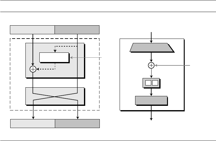
SECTION O.1 S-DES STRUCTURE 661
The round takes L
I−1
and R
I−1
from the previous round (or the initial permutation
box) and creates L
I
and R
I
, which go to the next round (or the final permutation box).
As we discussed in Chapter 5, we can assume that each round has two cipher elements,
a mixer and a swapper. Each of these elements is invertible. The swapper is obviously
invertible. It swaps the left half of the text with the right half. The mixer is invertible
because of the XOR operation. All noninvertible elements are collected inside the func-
tion, shown as f (R
I−1
, K
I
).
S-DES Function
The heart of S-DES is the S-DES function. The S-DES function applies an 8-bit key to
the rightmost 4 bits (R
I−1
) to produce a 4-bit output. This function is made up of four
sections: an expansion P-box, a whitener (which adds key), a group of S-boxes, and a
straight P-box as shown in Figure O.4.
Expansion P-box R
I−1
is a 4-bit input and K
I
is an 8-bit key, so we first need to expand
R
I−1
to 8 bits. Although the relationship between the input and output can be defined
mathematically, S-DES uses a table to define this P-box, as shown in Figure O.5. Note
that the number of output ports is 8, but the value range is only 1 to 4. Some of the inputs
go to more than one output.
Whitener (XOR) After the expansion permutation, S-DES uses the XOR operation
on the expanded right section and the round key. Note that the round key is used only in
this operation.
S-Boxes The S-boxes do the real mixing (confusion). S-DES uses two S-boxes, each
with a 4-bit input and a 2-bit output. See Figure O.6.
Figure O.4
A round in S-DES (encryption site)
Swapper
Mixer
Round
K
I
L
I–1
L
I
R
I–1
R
I
4 bits
4 bits
4 bits
4 bits
K
I
(8 bits)
8 bits
8 bits
4 bits
4 bits
4 bits
f ( R
I–1
, K
I
)
In
Out
Expansion P-box
XOR
Straight P-box
S-Boxes
S S
f ( R
I–1
, K
I
)

662 APPENDIX O SIMPLIFIED DES (S-DES)
The 8-bit data from the second operation is divided into two 4-bit chunks, and each
chunk is fed into a box. The result of each box is a 2-bit chunk; when these are combined,
the result is a 4-bit text. The substitution in each box follows a predetermined rule based on
a 4 × 4 table. The combination of bits 1 and 4 of the input defines one of four rows; the
combination of bits 2 and 3 defines one of the four columns, as shown in Figure 15.8.
Because each S-box has its own table, we need two tables, as shown in Figure O.6,
to define the output of these boxes. The values of the inputs (row number and column
number) and the values of the outputs are given as decimal numbers to save space.
These need to be changed to binary.
Example O.1
The input to S-box 1 is 1010
2
. What is the output?
Solution
If we write the first and the fourth bits together, we get 10 in binary, which is 2 in decimal. The
remaining bits are 01 in binary, which is 1 in decimal. We look for the value in row 2, column 1,
in Figure O.6 (S-box 1). The result in decimal is 2, which is 10 in binary. So the input 1010
2
yields the output 10
2
.
Figure O.5
Expansion P-box
Figure O.6
S-boxes
1
From 4
From 1
3 42
1 5 6 7 83 42
Expansion permutation table
Expansion
P-box
4 1 2 3 2 3 4 1
Table for S-box 2
0 1 2 3
2 0 1 3
3 0 1 0
2 1 0 3
0
1
2
3
0
1
2 3
Table for S-box 1
1 0 3 2
3 2 1 0
0 2 1 3
3 1 3 2
0
1
2
3
0 1 2 3
S-box 1 S-box 2
8-bit input
4 bits
4 bits
2 bits 2 bits
4-bit input
S-boxes
Each
S-box
1
1
2 3
2
4
0
0
1
2
3
1
2
3
Table
entry

SECTION O.1 S-DES STRUCTURE 663
Straight Permutation The last operation in the S-DES function is a straight permuta-
tion with a 4-bit input and a 4-bit output. The input/output relationship for this operation
is shown in Figure O.7 and follows the same general rule as previous permutation tables.
Key Generation
The round-key generator creates two 8-bit keys out of a 10-bit cipher key.
Straight Permutation
The first process is a straight permutation. It permutes the 10 bits in the key according
to a predefined table, as shown in Figure O.8.
Figure O.7
Straight P-Box
Figure O.8
Key generation
1 3 42
1 3 42
Permutation
table
Straight
P-box
2 4 3 1
5 bits 5 bits
10-bit
cipher key
Round
key 2
10 bits
Round-Key Generator
5 bits 5 bits
8 bits
8 bits
Round
key 1
Compression
P-box
Shift left
1 bit
Shift left
1 bit
5 bits 5 bits
Compression
P-box
Straight P-box
Table for straight P-box
3 5 2 7 4 10 1 9 8 6
Table for compression P-box
6 3 7 4 8 5 10 9
Shift left
2 bits
Shift left
2 bits

664 APPENDIX O SIMPLIFIED DES (S-DES)
Shift Left
After the straight permutation, the key is divided into two 5-bit parts. Each part
is shifted left (circular shift) r bits, where r is the round number (1 or 2). The two
parts are then combined to form a 10-bit unit. See Chapter 5 for a discussion of shift
operation.
Compression Permutation
The compression permutation (P-box) changes the 10 bits to 8 bits, which are used as a
key for a round. The compression permutation table is also shown in Figure O.8.
Example O.2
Table O.1 shows three cases of key generation.
Cases 2 and 3 show that none of the operations used in the key generation process is effec-
tive if the cipher key is made of all 0’s or all 1’s. These types of cipher keys need to be avoided, as
discussed in Chapter 6.
O.2 CIPHER AND REVERSE CIPHER
Using mixers and swappers, we can create the cipher and reverse cipher, each having
two rounds. The cipher is used at the encryption site; the reverse cipher is used at the
decryption site. To make the cipher and the reverse cipher algorithms similar, round 2
has only a mixer and no swapper. This is shown in Figure O.9.
Although the rounds are not aligned, the elements (mixer or swapper) are aligned.
We proved in Chapter 5 that a mixer is a self-invertible; so is a swapper. The final and
initial permutations are also inverses of each other. The left section of the plaintext at
Table O.1
Steps
Case 1 Case 2 Case 3
Cipher Key
After permutation
After splitting
1011100110
1100101110
L: 11001 R: 01110
0000000000
0000000000
L: 00000 R: 00000
1111111111
1111111111
L: 11111 R: 11111
Round 1:
Shifted keys:
Combined key:
Round Key 1:
L: 10011 R: 11100
1001111100
10111100
L: 00000 R: 00000
0000000000
00000000
L: 11111 R: 11111
1111111111
11111111
Round 2:
Shifted keys:
Combined key:
Round Key 2:
L: 01110 R: 10011
0111010011
11010011
L: 00000 R: 00000
0000000000
00000000
L: 11111 R: 11111
1111111111
11111111
S-DES is very vulnerable to brute-force attack because of its key size (10 bits).

SECTION O.2 CIPHER AND REVERSE CIPHER 665
the encryption site, L
0
, is enciphered as L
2
; L
2
at the decryption site is deciphered as
L
0
. The situation is the same with the right section.
A very important point we need to remember about the ciphers is that the
round keys (K
1
and K
2
) should be applied in the reverse order. At the encryption site,
round 1 uses K
1
and round 2 uses K
2
; at the decryption site, round 1 uses K
2
and round 2
uses K
1
.
Example O.3
We choose a random plaintext block and a random key, and determine what the ciphertext block
would be:
Let us show the result of each round and the text created before and after the rounds.
Table O.2 first shows the result of steps before starting the round. The plaintext goes through the
initial permutation to create completely different 8 bits. After this step, the text is split into two
Figure O.9
S-DES cipher and reverse cipher
There is no swapper in the second round.
Plaintext: 11110010 Key: 1011100110 Ciphertext: 11101011
8-bit plaintext
f
K
2
K
1
Round 1
Round 2
Round 1
Initial Permutation
Final Permutation
8-bit ciphertext
Encryption
Decr
y
ption
L
0
L
0
L
2
L
2
R
0
R
0
R
2
R
2
8-bit plaintext
Final Permutation
Initial Permutation
8-bit ciphertext
f
Round 2
f
f

666 APPENDIX O SIMPLIFIED DES (S-DES)
halves, L
0
and R
0
. The table shows the results of two rounds that involve mixing and swapping
(except for the second round). The results of the last rounds (L
2
and R
2
) are combined. Finally
the text goes through final permutation to create the ciphertext.
Some points are worth mentioning here. First, the right section out of each round is the same
as the left section out of the next round. The reason is that the right section goes through the
mixer without change, but the swapper moves it to the left section. For example, R
1
passes
through the mixer of the second round without change, but then it becomes L
2
because of the
swapper. The interesting point is that we do not have a swapper at the last round. That is why R
1
becomes R
2
instead of becoming L
2
.
Table O.2
Initial Processing
Plaintext: 11110010
After IP: 10111001
L
0
: 1011 R
0
: 1001
Cipher key: 1011100110
Round 1 L
1
: 1001 R
1
: 0111 Round key: 10111100
Round 2 L
2
: 1011 R
2
: 0111 Round key: 11010011
Final Processing Before IP
−1
: 10110111
Ciphertext: 11101011
Because of its small number of rounds, S-DES is more vulnerable to
cryptanalysis than DES.

667
APPENDIX P
Simplified AES (S-AES)
Simplified AES (S-AES), developed by Professor Edward Schaefer of Santa Clara Univer-
sity, is an educational tool designed to help students learn the structure of AES using smaller
blocks and keys. Readers may choose to study this appendix before reading Chapter 7.
P.1 S-AES STRUCTURE
S-AES is a block cipher, as shown in Figure P.1.
At the encryption site, S-AES takes a 16-bit plaintext and creates a 16-bit cipher-
text; at the decryption site, S-AES takes a 16-bit ciphertext and creates a 16-bit plaintext.
The same 16-bit cipher key is used for both encryption and decryption.
Rounds
S-AES is a non-Feistel cipher that encrypts and decrypts a data block of 16 bits. It uses
one pre-round transformation and two rounds. The cipher key is also 16 bits. Figure P.2
Figure P.1
Encryption and decryption with S-AES
16-bit key
Encryption
Decryption
S-AES
cipher
16-bit ciphertext
16-bit plaintext
S-AES
reverse cipher
16-bit ciphertext
16-bit plaintext

668 APPENDIX P SIMPLIFIED AES (S-AES)
shows the general design for the encryption algorithm (called the cipher); the decryp-
tion algorithm (called the inverse cipher) is similar, but the round keys are applied in
the reverse order.
In Figure P.2, the round keys, which are created by the key-expansion algorithm,
are always 16 bits, the same size as the plaintext or ciphertext block. In S-AES, there
are three round keys, K
0
, K
1
, and K
2
.
Data Units
S-AES uses five units of measurement to refer to data: bits, nibbles, words, blocks, and
states, as shown in Figure P.3.
Bit
In S-AES, a bit is a binary digit with a value of 0 or 1. We use a lowercase letter b to
refer to a bit.
Figure P.2 General design of S-AES encryption cipher
Figure P.3 Data units used in S-AES
Key
expansion
Cipher key
(16 bits)
Round Keys
(16 bits)
16-bit plaintext
S-AES
16-bit ciphertext
K
1
K
2
K
0
Round 1
Round 2
Pre-round
transformation
Word
n
0
n
1
n
2
n
3
Nibble
Block
n n
n
b
0
b
1
b
2
b
3
b
0
b
1
b
2
b
3
w w
w
n
0
n
1
n
0
n
1
Word
State
s
1,1
w
0
w
1
S
s
0,0
s
0,1
s
1,0
Nibble

SECTION P.1 S-AES STRUCTURE 669
Nibble
A nibble is a group of 4 bits that can be treated as a single entity, a row matrix of 4 bits,
or a column matrix of 4 bits. When treated as a row matrix, the bits are inserted into the
matrix from left to right; when treated as a column matrix, the bits are inserted into the
matrix from top to bottom. We use a lowercase bold letter n to refer to a nibble. Note
that a nibble is actually a single hexadecimal digit.
Word
A word is a group of 8 bits that can be treated as a single entity, a row matrix of two
nibbles, or a column matrix of 2 nibbles. When it is treated as a row matrix, the nibbles
are inserted into the matrix from left to right; when it is considered as a column matrix,
the nibbles are inserted into the matrix from top to bottom. We use the lowercase bold
letter w to refer to a word.
Block
S-AES encrypts and decrypts data blocks. A block in S-AES is a group of 16 bits. How-
ever, a block can be represented as a row matrix of 4 nibbles.
State
In S-AES, a data block is also referred to as a state. We use an uppercase bold letter S
to refer to a state. States, like blocks, are made of 16 bits, but normally they are treated
as matrices of 4 nibbles. In this case, each element of a state is referred to as s
r,c
, where
r (0 to 1) defines the row and the c (0 to 1) defines the column. At the beginning of the
cipher, nibbles in a data block are inserted into a state column by column, and in each
column, from top to bottom. At the end of the cipher, nibbles in the state are extracted
in the same way, as shown in Figure P.4.
Figure P.4
Block-to-state and state-to-block transformation
Insertion and
extraction flow
State
Block
n
0
n
1
n
2
n
3
Block
n
0
n
1
n
2
n
3
s
0,0
= n
0
s
1,0
= n
1
s
0,1
= n
2
s
1,1
= n
3
s
i mod 2, i/2
block
i
s
r, c
block
r + 2c

670 APPENDIX P SIMPLIFIED AES (S-AES)
Example P.1
Let us see how a 16-bit block can be shown as a 2 × 2 matrix. Assume that the text block is 1011
0111 1001 0110. We first show the block as 4 nibbles. The state matrix is then filled up, column
by column, as shown in Figure P.5.
Structure of Each Round
Figure P.6 shows that each transformation takes a state and creates another state to
be used for the next transformation or the next round. The pre-round section uses only
one transformation (AddRoundKey); the last round uses only three transformations,
(MixColumns transformation is missing).
At the decryption site, the inverse transformations are used: InvSubNibbles, Inv-
ShiftRows, InvMixColumns, and AddRoundKey (this one is self-invertible).
Figure P.5
Changing ciphertext to a state
Figure P.6
Structure of each round at the encryption site
Block (bits)
Block (nibbles)
0 1 1 11 1 1 0 010 0 1 1 01
7 6B 9
State
7 6
B 9
Round
Notes:
1. One AddRoundKey is applied
before round 1.
2. The third transformation is
missing in round 2.
State
SubNibbles
State
ShiftRows
State
MixColumns
State
State
AddRoundKey
Round
Key

SECTION P.2 TRANSFORMATIONS 671
P.2 TRANSFORMATIONS
To provide security, S-AES uses four types of transformations: substitution, permuta-
tion, mixing, and key-adding. We will discuss each here.
Substitution
Substitution is done for each nibble (4-bit data unit). Only one table is used for trans-
formations of every nibble, which means that if two nibbles are the same, the transfor-
mation is also the same. In this appendix, transformation is defined by a table lookup
process.
SubNibbles
The first transformation, SubNibbles, is used at the encryption site. To substitute a nib-
ble, we interpret the nibble as 4 bits. The left 2 bits define the row and the right 2 bits
define the column of the substitution table. The hexadecimal digit at the junction of the
row and the column is the new nibble. Figure P.7 shows the idea.
In the SubNibbles transformation, the state is treated as a 2 × 2 matrix of nibbles.
Transformation is done one nibble at a time. The contents of each nibble is changed,
but the arrangement of the nibbles in the matrix remains the same. In the process,
each nibble is transformed independently: There are four distinct nibble-to-nibble
transformations.
Figure P.7 also shows the substitution table (S-box) for the SubNibbles transforma-
tion. The transformation definitely provides confusion effect. For example, two nibbles,
A
16
and B
16
, which differ only in one bit (the rightmost bit), are transformed to 0
16
and
3
16
, which differ in two bits.
Figure P.7 SubNibbles transformations
SubNibbles involves four independent nibble-to-nibble transformations.
State
SubNibbles
SubNibbles table
Table
State
a
b
a
3
a
2
a
3
a
2
a
1
a
0
a
1
a
0
9 4 A B
D 1 8 5
6 2 0 3
C E F 7
00
01
10
11
00 01 10 11
InvSubNibbles table
a
3
a
2
a
1
a
0
A 5 9 B
1 7 8 F
6 0 2 3
C 4 D E
00
01
10
11
00 01 10 11

672 APPENDIX P SIMPLIFIED AES (S-AES)
InvSubNibbles
InvSubNibbles is the inverse of SubNibbles. The inverse transformation is also shown in
Figure P.7. We can easily check that the two transformations are inverses of each other.
Example P.2
Figure P.8 shows how a state is transformed using the SubNibbles transformation. The figure also
shows that the InvSubNibbles transformation creates the original state. Note that if the two nib-
bles have the same values, their transformation are also the same. The reason is that every nibble
uses the same table.
Permutation
Another transformation found in a round is shifting, which permutes the nibbles. Shift-
ing transformation in S-AES is done at the nibble level; the order of the bits in the nib-
ble is not changed.
ShiftRows
In the encryption, the transformation is called ShiftRows and the shifting is to the left.
The number of shifts depends on the row number (0, 1) of the state matrix. This means
row 0 is not shifted at all and row 1 is shifted 1 nibble. Figure P.9 shows the shifting
transformation. Note that the ShiftRows transformation operates one row at a time.
Figure P.8
SubNibble transformation for Example P.2
Figure P.9
ShiftRows transformation
State
4 3
0 2
State
SubNibbles
InvSubNibbles
D B
9 A
ShiftRow
Shift left
Row 0: no shift
Row 1: 1-nibble shift
State State

SECTION P.2 TRANSFORMATIONS 673
InvShiftRows
In the decryption, the transformation is called InvShiftRows and the shifting is to the
right. The number of shifts is the same as the number of the row (0, 1) in the state
matrix.
Example P.3
Figure P.10 shows how a state is transformed using ShiftRows. The figure also shows that the
InvShiftRows transformation creates the original state.
Mixing
The substitution provided by the SubNibbles transformation changes the value of the
nibble based only on the nibble’s original value and an entry in the table; the process
does not include the neighboring nibbles. We can say that SubNibbles is an intra-nibble
transformation. The permutation provided by the ShiftRows transformation exchanges
nibbles without permuting the bits inside the bytes. We can say that ShiftRows is a
nibble-exchange transformation. We also need an inter-nibble transformation that
changes the bits inside a nibble, based on the bits inside the neighboring nibbles. We
need to mix nibbles to provide diffusion at the bit level.
The mixing transformation changes the contents of each nibble by taking 2 nibbles
at a time and combining them to create 2 new nibbles. To guarantee that each new nib-
ble is different (even if the old nibbles are the same), the combination process first mul-
tiplies each nibble with a different constant and then mixes them. The mixing can be
provided by matrix multiplication. As we discussed in Chapter 2, when we multiply a
square matrix by a column matrix, the result is a new column matrix. Each element in
the new matrix depends on the two elements of the old matrix after they are multiplied
by row values in the constant matrix.
MixColumns
The MixColumns transformation operates at the column level; it transforms each col-
umn of the state into a new column. The transformation is actually the matrix multipli-
cation of a state column by a constant square matrix. The nibbles in the state column
and constants matrix are interpreted as 4-bit words (or polynomials) with coefficients in
The ShiftRows and InvShiftRows transformations are inverses of each other.
Figure P.10
ShiftRows transformation in Example P.3
State
State
ShiftRows
InvShiftRows
F
2
6
C
2
F
6
C

674 APPENDIX P SIMPLIFIED AES (S-AES)
GF(2). Multiplication of bytes is done in GF(2
4
) with modulus (x
4
+ x + 1) or (10011).
Addition is the same as XORing of 4-bit words. Figure P.11 shows the MixColumns
transformation.
InvMixColumns
The InvMixColumns transformation is basically the same as the MixColumns transfor-
mation. If the two constant matrices are inverses of each other, it is easy to prove that
the two transformations are inverses of each other.
Figure P.12 shows how a state is transformed using the MixColumns transformation.
The figure also shows that the InvMixColumns transformation creates the original one.
Note that equal bytes in the old state, are not equal any more in the new state. For
example, the two bytes F in the second row are changed to 4 and A.
Key Adding
Probably the most important transformation is the one that includes the cipher key.
All previous transformations use known algorithms that are invertible. If the cipher
Figure P.11
MixColumns transformation
The MixColumns and InvMixColumns transformations are inverses of each other.
Figure P.12
The MixColumns transformation in Example 7.5
MixColumns
Constant
= ⋅
1 4
4 1
9 2
2 9
C
C
–1
State
State
State
F F
6 C
State
MixColumns
InvMixColumns
4 A
F 5

SECTION P.3 KEY EXPANSION 675
key is not added to the state at each round, it is very easy for the adversary to find the
plaintext, given the ciphertext. The cipher key is the only secret between Alice and
Bob in this case.
S-AES uses a process called key expansion (discussed later in this appendix) that
creates three round keys from the cipher key. Each round key is 16 bits longit is
treated as two 8-bit words. For the purpose of adding the key to the state, each word is
considered as a column matrix.
AddRoundKey
AddRoundKey also proceeds one column at a time. It is similar to MixColumns in this
respect. MixColumns multiplies a constant square matrix by each state column;
AddRoundKey adds a round key word with each state column matrix. The operations in
MixColumns are matrix multiplication; the operations in AddRoundKey are matrix
addition. The addition is performed in the GF(2
4
) field. Because addition and subtrac-
tion in this field are the same, the AddRoundKey transformation is the inverse of itself.
Figure P.13 shows the AddRoundKey transformation.
P.3 KEY EXPANSION
The key expansion routine creates three 16-bit round keys from one single 16-bit cipher
key. The first round key is used for pre-round transformation (AddRoundKey); the
remaining round keys are used for the last transformation (AddRoundKey) at the end of
round 1 and round 2.
The key-expansion routine creates round keys word by word, where a word is an
array of 2 nibbles. The routine creates 6 words, which are called
w
0
, w
1
, w
2
,
…
, w
5
.
Creation of Words in S-AES
Figure P.14 shows how 6 words are made from the original key.
The AddRoundKey transformation is the inverse of itself.
Figure P.13 AddRoundKey transformation
AddRoundKey
Key word
= +
State State

676 APPENDIX P SIMPLIFIED AES (S-AES)
The process is as follows:
1. The first two words (w
0
, w
1
) are made from the cipher key. The cipher key
is thought of as an array of 4 nibbles (n
0
to n
3
). The first 2 nibbles (n
0
to n
1
)
become w
0
; the next 2 nibbles (n
2
to n
3
) become w
1
. In other words, the concate-
nation of the words in this group replicates the cipher key.
2. The rest of the words (w
i
for i = 2 to 5) are made as follows:
a. If (i mod 2) = 0, w
i
= t
i
⊕ w
i−2
. Here t
i
, a temporary word, is the result of apply-
ing two routines, SubWord and RotWord, on w
i−1
and XORing the result with a
round constant, RC[N
r
], where N
r
is the round number.
In other words, we have
The words w
2
and w
4
are made using this process.
b. If (i mod 2) ≠ 0, w
i
= w
i−1
⊕ w
i−2
. Referring to Figure P.14, this means each
word is made from the word at the left and the word at the top. The words w
3
and w
5
are made using this process.
RotWord
The RotWord (rotate word) routine is similar to the ShiftRows transformation, but it is
applied to only one row. The routine takes a word as an array of 2 nibbles and shifts
each nibble to the left with wrapping. In S-AES, this is actually swapping the 2 nibbles
in the word.
SubWord
The SubWord (substitute word) routine is similar to the SubNibble transformation, but
it is applied only to 2 nibbles. The routine takes each nibble in the word and substitutes
another nibble for it using the SubNibble table in Figure P.7.
Figure P.14 Creation of words in S-AES
t
i
= SubWord (RotWord (w
i−1
)) ⊕ RCon [N
r
]
t
2
Cipher key
Pre-round
Round 1
Round 2
t
4
w
0
w
1
w
2
w
3
w
4
w
5
n
0
n
1
t
i
RCon[N
r
]
RCon[1] = 80
16
RCon[2] = 30
16
Making of t
i
(temporary) words i = 2N
r
, where N
r
is the round number
W
i−1
RotWord SubWord
n
2
n
3

SECTION P.4 CIPHERS 677
Round Constants
Each round constant, RC, is a 2-nibble value in which the rightmost nibble is always
zero. Figure P.14 also shows the value of RCs.
Example P.4
Table P.1 shows how the keys for each round are calculated assuming that the 16-bit cipher key
agreed upon by Alice and Bob is 2475
16
.
In each round, the calculation of the second word is very simple. For the calculation of the
first word we need to first calculate the value of the temporary word (t
i
), as shown below:
P.4 CIPHERS
Now let us see how S-AES uses the four types of transformations for encryption and
decryption. The encryption algorithm is referred to as the cipher and the decryption
algorithm as the inverse cipher.
S-AES is a non-Feistel cipher, which means that each transformation or group
of transformations must be invertible. In addition, the cipher and the inverse cipher
must use these operations in such a way that they cancel each other. The round keys
must also be used in the reverse order. To comply with this requirement, the transfor-
mations occur in a different order in the cipher and the reverse cipher, as shown in
Figure P.15.
First, the order of SubNibbles and ShiftRows is changed in the reverse cipher.
Second, the order of MixColumns and AddRoundKey is changed in the reverse
cipher. This difference in ordering is needed to make each transformation in the
cipher aligned with its inverse in the reverse cipher. Consequently, the decryption
algorithm as a whole is the inverse of the encryption algorithm. Note that the round
keys are used in the reverse order.
Table P.1
Key expansion example
Round
Values of
t’s
First word
in the round
Second word
in the round
Round Key
0
w
0
=
24 w
1
= 75 K
0
= 2475
1 t
2
= 95 w
2
= 95 ⊕⊕
⊕⊕
24 = B1 w
3
= B1 ⊕⊕
⊕⊕
75 = C4 K
0
= B1C4
2 t
4
= EC w
4
= B1 ⊕⊕
⊕⊕
EC = 5D w
5
= 5D ⊕⊕
⊕⊕
C4 = 99 K
2
= 5D99
RotWord (75) = 57 → SubWord (57) = 15 → t
2
= 15 ⊕ RC[1] = 15 ⊕ 80 = 95
RotWord (C4) = 4C → SubWord (4C) = DC → t
4
= DC ⊕ RC[2] = DC ⊕ 30 = EC

678 APPENDIX P SIMPLIFIED AES (S-AES)
Example P.5
We choose a random plaintext block, the cipher key used in Example P.4, and determine what the
ciphertext block would be:
Figure P.16 shows the value of states in each round. We are using the round keys generated in
Example P.4.
Figure P.15 Cipher and inverse cipher of the original design
Plaintext: 1A23
16
Key: 2475
16
Ciphertext: 3AD2
16
Figure P.16 Example P.5
Round 1
Round 1
Plaintext
Ciphertext
Key Expansion
Ke
y
Expansion
W
0
−W
1
W
0
−W
1
W
2
−W
3
W
2
−W
3
W
4
−W
5
W
4
−W
5
Plaintext
Round 2
Round 2
AddRoundKey
AddRoundKey AddRoundKey
SubNibbles
InvSubNibbles
ShiftRows
InvShiftRows
AddRoundKey
InvMixColumns
AddRoundKey
AddRoundKey
SubNibbles
InvSubNibbles
ShiftRows
InvShiftRows
MixColumns
Inverses
Cipher key
Cipher key
E
3
6
5
E
3
6
5
F
B
8
1
8
B
F
1
2
D
B
8
3
6
F
4
3
6
F
4
B
8
7
D
7
6
B
4
A
3
2
D
A
1
3
2
SR
SR: ShiftRows
SR
MC
MC: MixColumns
SN
SN: SubNibbles
SN
ARK
Preround
K
0
= 2475
16
K
1
= B1C4
16
K
2
= 5D99
16
Round 1
Round 2
ARK: AddRoundKey
ARK
ARK

679
APPENDIX Q
Some Proofs
This appendix presents some proofs for theorems used in Chapters 2 and 9. The proofs
are mostly short and informal so that they will be useful for students in a cryptography
course. The reader interested in more details can consult books on number theory.
Q.1 CHAPTER 2
This section presents some proofs for theorems on divisibility, Euclidean algorithms,
and congruence.
Divisibility
Following are proofs for several theorems on divisibility.
Theorem Q.1: Division Relation (Algorithm)
For integer a and b with b > 0, there exist integers q and r such that a = q × b + r.
Theorem Q.2
If a | 1, then a = ±1.
Proof:
Consider an arithmetic progression in the form:
…, −3 × b, −2 × b, −1 × b, 0 × b, 1 × b, 2 × b, 3 × b, …
It is obvious that integer a is either equal to one of the terms or between two consecutive
terms. In other words, a = q × b + r, where q × b is a term in the above progression and r is the
offset from the term.
Proof:
a | 1 → 1 = x × a, where x is an integer.
This means: (x = 1 and a = 1) or (x = −1 and a = −1).
Therefore: a = ±1.

680 APPENDIX Q SOME PROOFS
Theorem Q.3
If a | b and b | a, then a = ±b.
Theorem Q.4
If a | b and b | c, then a | c.
Theorem Q.5
If a | b and a | c, then a | (b + c).
Theorem Q.6
If a | b and a | c, then a | (m × b + n × c), where m and n are arbitrary integers.
Euclidean Algorithms
We used Euclidean and extended Euclidean algorithms in Chapter 2. Following are
proofs of two theorems related to these algorithms.
Proof:
a | b → b = x × a, where x is an integer.
b | a → a = y × b, where y is an integer.
We have a = y × (x × a) = (y × x) × a. → y × x = 1.
This means: (x = 1 and y = 1) or (x = −1 and y = −1).
Therefore: a = y × b → a = ± b.
Proof:
a | b → b = x × a, where x is an integer.
b | c → c = y × b, where y is an integer.
We have c = y × (x × a) = (y × x) × a.
Therefore, a | c.
Proof:
a | b → b = x × a, where x is an integer.
a | c → c = y × a, where y is an integer.
We have b + c = (x + y) × a.
Therefore, a | (b + c).
Proof:
a | b → b = x × a, where x is an integer.
a | c → c = y × a, where y is an integer.
We have m × b + n × c = m × (x × a) + n × (y × a) = (m × x + n × y) × a.
Therefore, a | (m × b + n × c).

SECTION Q.1 CHAPTER 2 681
Theorem Q.7
If a = b × q + r (r is the remainder of dividing a by b), then gcd (a, b) = gcd (b, r).
As we saw in Chapter 2, this theorem is the basis of the Euclidean algorithm to find the
greatest common divisor of two integers.
Theorem Q.8
If a and b are integers, not both of which zero, then there exist integers x and y such that
gcd (a, b) = x × a + y × b.
As we saw in Chapter 2, this theorem is the basis of the extended Euclidean algorithm.
Congruence
Following are proofs of some theorems about congruence used in Chapter 2.
Theorem Q.9
If a, b, and n are integers with n > 0, then a ≡ b (mod n) if and only if there exists an
integer q such that a = q × n + b.
Proof:
Assume that E is the set of all common divisors of a and b. Every element of E divides a and
b; therefore, it divides r = a − b × q. This means that E is the set of all common divisors of
a, b, and r.
Assume that F is the set of all common divisors of b and r. Every element of F divides b and
r; therefore, it divides a = b × q + r. This means that F is the set of all common divisors of a, b,
and r.
This means that E = F → a, b, and r have the same set of common divisors.
Therefore, gcd (a, b) = gcd (b, r).
Proof:
Assume that D is the set of all values of (x × a + y × b), with d the smallest nonzero value.
We can write a = q × d + r → r = a − q × d = (1 − q × x)a + (−q × y)b, where 0 ≤ r < d.
This implies that r is a member of D. But because r < d, then r = 0 or d | a.
With a similar argument, we can show that d | b.
Therefore, d is the common divisor of a and b.
Any other divisor of a and b divides d = x × a + y × b. Therefore, d must be the gcd (a, b).
Proof:
If a ≡ b (mod n), then n | (a − b), which means there is an integer q such that a − b = q × n.
Therefore, we have a = q × n + b.
If there is an integer q such that a = q × n + b, then a − b = q × n, which means n | (a − b).
Therefore, we have a ≡ b (mod n).

682 APPENDIX Q SOME PROOFS
Theorem Q.10
If a, b, c, and n are integers with n > 0, such that a ≡ b (mod n), then
a. a + c ≡ b + c (mod n).
b. a − c ≡ b − c (mod n).
c. a × c ≡ b × c (mod n).
Theorem Q.11
If a, b, c, d, and n are integers with n > 0, such that a ≡ b (mod n) and c ≡ d (mod n),
then
a. a + c ≡ b + d (mod n).
b. a − c ≡ b − d (mod n).
c. a × c ≡ b × d (mod n).
Q.2 CHAPTER 9
This section presents some proofs of the theorems used in Chapter 9. We leave the dis-
cussion of the lengthy proofs, such as the proof of Chinese remainder theorem, to
books in number theory.
Primes
We prove just one theorem about primes.
Theorem Q.12
If n is a composite, then there is a prime divisor p such that p ≤ .
Proof: Note that a ≡ b (mod n) → n | (a − b).
a. (a + c) − (b + c) = a − b. Because n | (a − b), n | (a + c) − (b + c).
Therefore, a + c ≡ b + c (mod n).
b. (a − c) − (b − c) = a − b. Because n | (a − b), n | (a − c) − (b − c).
Therefore, a − c ≡ b − c (mod n).
c. (a × c) − (b × c) = (a − b) × c. Because n | (a − b), n | (a − b) × c.
Therefore, a × c ≡ b × c (mod n).
Proof: Note that a ≡ b (mod n) → (a − b) = k × n; c ≡ d (mod n) → (c − d) = l × n
a. (a + c) − (b + d) = (a − b) + (c − d) = k × n + l × n = (k + l) × n.
Therefore, a + c ≡ b + d (mod n).
b. (a − c) − (b − d) = (a − b) − (c − d) = k × n − l × n = (k − l) × n.
Therefore, a − c ≡ b − d (mod n).
c. a × c − b × d = c × (a − b) + b × (c − d) = (c × k + b × l) × n.
Therefore, a × c ≡ b × d (mod n).
n

SECTION Q.2 CHAPTER 9 683
This theorem is used in the sieve of Eratosthenes to find all prime factors of n.
Euler’s Phi-Function
Following are three proofs related to the Euler’s phi-function.
Theorem Q.13
If p is a prime, then φ(p) = p − 1.
This theorem is part of the Euler’s phi-function.
Theorem Q.14
If p is a prime and e is a positive integer, then φ(p
e
) = p
e
− p
e−1
.
This theorem is another part of Euler’s phi-function.
Theorem Q.15
If n is a composite with prime factorization of Π p
i
e
i
, then φ(n) = Π (p
i
e
i
− p
i
e
i
−1
).
This theorem is the generalization of Euler’s phi-function.
Proof:
Because n is a composite, n = a × b.
If p is the smallest prime divisor of n, then p ≤ a and p ≤ b.
Therefore, p
2
≤ a × b or p
2
≤ n → p ≤
Proof:
Because p is a prime, all integers less than p, except p itself, are relatively prime to p.
Therefore, φ(p) = p − 1.
Proof:
The integers that are not relatively prime to p
e
are (1 × p), (2 × p), . . . , (p
e−1
× p). All of these
integers have the common divisor p with p
e
. The total number of these integers is p
e−1
. The
rest of the integers are relatively prime with p
e
.
Therefore, φ(p
e
) = p
e
− p
e−1
Proof:
The proof is based on the fact that the φ(n) is a multiplicative function in which φ(m × n) =
φ(m) × φ(n) if m and n are relatively prime. Because the terms in the prime factorization of n
are relatively prime, φ(
Π p
i
e
i
) = Πφ(p
i
e
i
).
Therefore, φ(n) = Π (p
i
e
i
− p
i
e
i
−1
).
n

684 APPENDIX Q SOME PROOFS
Fermat’s Little Theorem
Following are proofs of two theorems related to Fermat’s little theorem.
Theorem Q.16
If p is a prime and a is a positive integer relatively prime to p, then a
p−1
≡ 1 (mod p).
This theorem is the first version of Fermat’s little theorem.
Theorem Q.17
If p is a prime and a is a positive integer, then a
p
≡ a (mod p).
This theorem is the second version of Fermat’s little theorem.
Euler’s Theorem
Following is a proof of one theorem related to the first version of Euler’s theorem. We
proved the second version in Chapter 9.
Theorem Q.18
If n and a are coprime, then a
φ(n)
≡ 1 (mod n).
Proof:
It can be proven that the residues of the terms a, 2a, . . ., (p − 1)a modulo p are 1, 2, . . .,
(p − 1), but not necessarily in the same order.
The result of a × 2a × ··· (p − 1)a is [(p − 1)]! a
p−1
.
The result of 1 × 2 × ··· × (p − 1) is [(p − 1)]!
This means [(p − 1)]! a
p−1
≡ [(p − 1)]! (mod p)
Therefore, a
p−1
≡ 1 (mod p), when we divide both sides by [(p − 1)]!
Proof:
If a and p are coprime, we multiply both sides of the congruence using the result of the previ-
ous theorem to get a
p
≡ a (mod p).
If p | a, then a
p
≡ a ≡ 0 (mod p).
Proof:
Assume that the elements in Z
n
∗
are r
1
, r
2
, . . ., r
φ(n)
.
We create another set ar
1
, ar
2
, …, ar
φ(n)
by multiplying each element in Z
n
∗
by a.
It can be
proven that each element in this new set is congruent to an element in Z
n
∗
(not necessarily in
the same order).
Thus, ar
1
× ar
2
× ··· × ar
φ(n)
≡
r
1
× r
2
× ··· × r
φ(n)
(mod n)
We have a
φ(n)
[r
1
× r
2
× ··· × r
φ(n)
]
≡
r
1
× r
2
× ··· × r
φ(n)
(mod n)
Therefore, a
φ(n)
≡ 1 (mod n).

SECTION Q.2 CHAPTER 9 685
Fundamental Theorem of Arithmetic
Following is a partial proof of the Fundamental Theorem of Arithmetic.
Theorem Q.19
Any positive integer n greater than 1 can be written as the product of prime.
This theorem is a partial proof of the Fundamental Theorem of Arithmetic. To
completely prove this theorem, we need to show the product is unique. But we leave
this part to books on number theory.
Proof:
We use induction. The base case is n = 2, which is a prime. For the general case, assume that
all positive integers less than n can be written as the product of primes, we prove that n can
also be written as the product of primes.
We can have two cases: n is a prime or n is a composite.
1. If n is prime, it can be written as the product of one prime, itself.
2. If n is a composite, then we can write n = a × b. Because a and b are both less than n, each
can be written as the product of primes according to the assumption. Therefore, n can be
written as the product of primes.

687
Glossary
A
A5/1
A member of the A5 family of stream ciphers used in the Global System for Mobile
Communication (GSM).
abelian group A commutative group.
access control
A security service that protects against unauthorized access to data. Also a
security mechanism that verifies a user’s right to access the data.
active attack
An attack that may change the data or harm the system.
additive cipher
The simplest monoalphabetic cipher in which each character is encrypted by
adding its value with a key.
additive inverse
In modular arithmetic, a and b are additive inverses of each other if (b + a)
mod n = 0.
AddRoundKey
In AES, an operation that adds a round key word with each state column
matrix.
Advanced Encryption Standard (AES)
A non-Feistel symmetric-key block cipher pub-
lished by the NIST.
affine cipher A cipher that combines the additive and multiplicative ciphers.
aggressive mode
In IKE, a mode that is a compressed version of the corresponding main
mode using three message exchange instead of six.
Alert Protocol In SSL and TLS, a protocol for reporting errors and abnormal conditions.
algebraic structure
A structure consists of a set of elements and operations that are defined
for the sets. Groups, rings, and fields are examples of algebraic structures.
anonymous Diffie-Hellman
In SSL and TLS, the original Diffie-Hellman protocol.
associativity
In an algebraic structure, if a, b, and c are elements of the underlying set and
•
denotes
one of the operations, the associative property guarantees that (a
•
b)
•
c = a
•
(b
•
c).
asymmetric-key cryptosystem
A cryptosystem that uses two different keys for encryption
and decryption: a public key for encryption and a private key for decryption.
asymmetric-key encipherment
An encipherment using an asymmetric-key cryptosystem.
authentication
A security service that checks the identity of the party at the other end of the
line.
688 GLOSSARY
authentication exchange
A security mechanism in which two entities exchange a set of
messages to prove their identity to each other.
Authentication Header (AH)
A protocol in IPSec that provides message integrity and
authentication.
authentication server (AS)
The server that plays the role of the KDC in the Kerberos
protocol.
autokey cipher
A stream cipher in which each subkey in the stream is the same as the previ-
ous plaintext character. The first subkey is the secret between two parties.
availability
This component of information security requires that the information created and
stored by an organization to be available to authorized entities.
avalanche effect
A desired characteristic in a cipher in which a small change in the plaintext
or key results in a large change in the ciphertext.
B
binary operation
An operation that takes two inputs and creates one output.
biometrics
The measurement of physiological or behavioral features that identify a person.
birthday problem
A classical problem concerning the probability that n people have distinct
birthdays where n
≤
365.
bit
A binary digit with a value of 0 or 1.
bit-oriented cipher
A cipher in which the symbols in the plaintext, the ciphertext, and the
key are bits.
blind signatures
A patented scheme developed by David Chaum that allows a document to
get signed without revealing the contents of the document to the signer.
block
A group of bits treated as one unit.
block cipher
A type of cipher in which blocks of plaintext are encrypted one at a time using
the same cipher key.
broadcast attack
A type of attack on RSA that can be launched if one entity sends the same
small message to a group of recipients with the same low encryption exponent.
brute-force attack A type of attack in which the attacker tries to use all possible keys to find
the cipher key.
bucket brigade attack
See man-in-the-middle attack.
byte
A group of eight bits. An octet.
C
Caesar cipher An additive cipher with a fixed-value key used by Julius Caesar.
CBC-MAC
See CMAC.
certification authority (CA)
An organization that binds a public key to an entity and issues
a certificate.
challenge-response authentication
An authentication method in which the claimant
proves that she knows a secret without sending it.
ChangeCipherSpec Protocol In SSL and TLS, the protocol that allows the movement
from the pending state to the active state.
GLOSSARY 689
characteristic polynomial
In an LFSR, the polynomial representing the feedback function.
character-oriented cipher
A cipher in which the symbols in the plaintext, the ciphertext,
and the key are characters.
Chinese remainder theorem (CRT)
A theorem that proves that there exists a unique
solution for a set of congruent equations with one variable if the moduli are relatively prime.
chosen-ciphertext attack
A type of attack in which the adversary chooses a set of cipher-
texts and somehow finds the corresponding plaintexts. She then analyzes the ciphertext/plaintexts
pairs to find the cipher key.
chosen-message attack An attack in which the attacker somehow makes Alice sign one or
more messages. The attacker later creates another message, with the content she wants, and
forges Alice’s signature on it.
chosen-plaintext attack
A type of attack in which the adversary chooses a set of plaintexts
and somehow finds the corresponding ciphertexts. She then analyzes the plaintext/ciphertext
pairs to find the cipher key.
cipher
A decryption and/or encryption algorithm.
cipher feedback (CFB) mode
A mode of operation in which each r-bit block is exclusive-
ored with an r-bit key, which is part of an encrypted register.
cipher block chaining (CBC) mode
A mode of operation similar to ECB, but each block
is first exclusive-ored with the previous ciphertext.
cipher suite
In SSL and TLS, the combination of key exchange, hash, and encryption algo-
rithms.
ciphertext The message after being encrypted.
ciphertext-only attack A type of attack in which the intruder has only the intercepted
ciphertext to analyze.
circular shift operation
An operation in modern block ciphers that removes k bits from one
end and inserts them at the other end.
claimant
In entity authentication, the entity whose identity needs to be proved.
clogging attack
In the Diffie-Hellman method, a type of attack in which an intruder can send
many half-keys to one of the parties, pretending that they are from different sources. The attack
may eventually result in denial of service.
closure
In an algebraic structure, if a and b are elements of the underlying set and
•
denotes
one of the operations, the closure property guarantees that c = a
• b is also a member of the set.
CMAC
A standard MAC defined by NIST (FIPS 113) as the Data Authentication Algorithm.
The method is similar to the cipher block chaining (CBC) mode.
coefficient
In a polynomial, the constant value in each term.
collision resistance
A property of a cryptographic hash function that ensures that the intruder
cannot find two messages that hash to the same digest.
column matrix
A matrix with only one column.
combine operation
An operation in some block ciphers that concatenates two equal-length
blocks to create a new block.
common modulus attack
A type of attack on RSA that can be launched if a community
uses a common modulus.
commutative group
A group in which the binary operation satisfies the commutative property.
690 GLOSSARY
commutativity
In an algebraic structure, if a an b are elements of the underlying set and
•
denotes one of the operations, the commutative property guarantees that a
•
b = b
•
a.
composite
A positive integer with more than two divisors.
composition
Composition of two functions f and g is defined as g(f (x)), which means that
first the function f is applied to the domain x, and then the function g is applied to the range of f.
compression function A function that creates a fixed-size digest out of a variable-size message.
compression P-box A P-box with n inputs and m outputs, where n > m.
confidentiality A security goal that defines procedures to hide information from an unautho-
rized entity.
confusion A desired property of a block cipher introduced by Shannon that hides the relation-
ship between the ciphertext and the key. This will frustrate the adversary who tries to use the
ciphertext to find the key.
congruence If n is a positive integer, two integers a and b are said to be congruent modulo n,
a
≡ b (mod n), if a − b = kn, for some integer k.
congruence operator The operator (≡) used in a congruence relation.
connection In SSL and TLS, the process that allows two entities to exchange two random
numbers and create the keys and parameters needed for communication.
cookie A text that holds some information about the receiver and must be returned to the
sender untouched.
Coppersmith theorem attack A type of attack on RSA that can be launched if the value of
the encryption exponent is small.
coprime See relatively prime.
counter (CTR) mode A mode of operation in which there is no feedback. It is similar to
OFB, but a counter is used instead of a shift register.
cryptanalysis The science and art of breaking codes.
cryptographic hash function A function that creates a much shorter output from an input.
To be useful, the function must be resistant to image, preimage, and collision attacks.
Cryptographic Message Syntax (CMS) The syntax used in S/MIME that defines the
exact encoding scheme for each content type.
cryptography The science and art of transforming messages to make them secure and
immune to attacks.
cyclic subgroup A subgroup that can be generated using the power of an element in the
group.
cycling attack A type of attack on RSA that uses the fact that the ciphertext is a permutation
of the plaintext; continuous encryption of the ciphertext will eventually result in the plaintext.
D
data confidentiality A security service designed to protect data from disclosure attacks,
snooping, and traffic analysis.
Data Encryption Standard (DES) A symmetric-key block cipher using rounds of Feistel
ciphers and standardized by NIST.
data expansion function In TLS, a function that uses a predefined HMAC to expand a
secret into a longer one.

GLOSSARY 691
data integrity A security service designed to protect data from modification, insertion, dele-
tion, and replaying. Also, a security mechanism that appends a short checkvalue to the data that
has been created by a specific process from the data itself. The checkvalue can be use to protect
the integrity of data.
Davies-Meyer scheme A hash function scheme basically the same as the Rabin scheme
except that it uses forward feed to protect against meet-in-the-middle attack.
deciphering See decryption.
decoding This term has many definitions. In this text, one of the meanings is to transform an
n-bit integer into a 2
n
-bit string with only a single 1. The position of the single 1 is the value of
the integer.
decryption De-scrambling of the ciphertext to create the original plaintext.
decryption algorithm An algorithm used for decryption.
denial of service The only attack on the availability goal that may slow down or interrupt the
system.
determinant A scalar value defined for a square matrix. A matrix is reversible if its determi-
nant is nonzero.
dictionary attack An attack in which the intruder is interested in finding one password
regardless of the user ID.
differential cryptanalysis A type of chosen-plaintext attack introduced by Biham and
Shamir that uses the differential profile of S-boxes to attack a product cipher.
Diffie-Hellman protocol A protocol for creating a session key without using a KDC.
diffusion A desired property of a block cipher introduced by Shannon that hides the relationship
between the ciphertext and the plaintext. This will frustrate the adversary who uses ciphertext statis-
tics to find the plaintext.
digital signature A security mechanism in which the sender can electronically sign the mes-
sage and the receiver can verify the message to prove that the message is indeed signed by the
sender.
Digital Signature Algorithm (DSA) The digital signature algorithm used by the Digital
Signature Standard (DSS).
digital signature scheme A method of systematic creation of a secure digital signature.
Digital Signature Standard (DSS) The digital signature standard adopted by NIST under
FIPS 186.
digram A two-letter string.
discrete logarithm The integer d is called the discrete logarithm of a to the base r if r
d
≡ a
(mod n), where r is a primitive root of n, and a and n are relatively prime.
distributivity In an algebraic structure with two operations
and •, distributivity of
over •
means that for all a, b, and c elements of the underlying set, we have a
(b • c) = (a
b) • (a
c)
and (a
• b)
c = (a
c) • (b
c).
divisibility If a and b are integers and a ≠ 0, we say that a divides b if there is an integer k
such that b = k
× a.
divisibility test The most elementary deterministic method for a primality test in which the
number is declared a prime if all numbers less than cannot divide it.
double DES (2DES) A cipher that uses two instances of DES ciphers for encryption and two
instances of reverse ciphers for decryption.
n
692 GLOSSARY
double transposition cipher
A transposition cipher in which the same encryption or dec-
ryption algorithm is repeated with two keys or the same key.
E
electronic cookbook (ECB) mode
A mode of operation in which each block is encrypted
independently with the same cipher key.
electronic mail (e-mail)
An electronic version of a postal mail system.
ElGamal cryptosystem
An asymmetric-key cryptosystem, devised by ElGamal, which is
based on the discrete logarithm problem.
ElGamal signature scheme
The digital signature scheme derived from the ElGamal cryp-
tosystem using the same keys.
elliptic curves
Cubic equations in two variables of the following form: y
2
+ b
1
xy + b
2
y = x
3
+
a
1
x
2
+ a
2
x + a
3
.
elliptic curves cryptosystem
An asymmetric-key cryptosystem based on elliptic curves.
elliptic curves logarithm problem
Given two points, e
1
and e
2
, on an elliptic curve, this
problem must find the multiplier r such that e
2
= r × e
1
.
elliptic curves digital signature scheme (ECDSA)
A digital signature algorithm based
on DSA but using elliptic curves.
Encapsulating Security Payload (ESP)
A protocol in IPSec that provides source authen-
tication, integrity, and privacy.
encipherment
See encryption.
encoding
The term has many definitions. In this text, one of the meanings is to transform a 2
n
-bit
string with only a single 1 to an n-bit integer. The position of the single 1 defines the value of the
integer.
encryption Producing ciphertext from plaintext using a cryptosystem.
Enigma machine
A machine based on the principle of rotor ciphers. It was used by the
German army during World War II.
entity authentication A technique designed to let one party prove the identity of another
party. The entity whose identity needs to be proved is called the claimant; the party that tries to
prove the identity of the claimant is called the verifier.
ephemeral Diffie-Hellman
A version of the Diffie-Hellman key exchange protocol in
which each party sends a Diffie-Hellman key signed by its private key.
Euclidean algorithm
An algorithm to find the greatest common divisor of two positive
integers.
Euler’s phi-function
A function that finds the number of integers that are both smaller than
n and relatively prime to n.
Euler’s theorem
A generalization of Fermat’s little theorem in which the modulus is an
integer.
existence of identity
In an algebraic structure, if a is an element of the underlying set and
•
defines one of the operations, this property guarantees that there exists an element e, called the
identity element, such that a
•
e = e
•
a = a.
existence of inverse
In an algebraic structure, if a is an element of the underlying set and
•
defines one of the operations, this property guarantees that there exists an element a
′
, called the
inverse element, such that a
•
a
′
= a
′
•
a = e, where e is the identity element.
GLOSSARY 693
existential forgery A type of signature forgery in which the forger may be able to create a
valid message-signature pair, but not one that she can really use.
expansion P-box A P-box with n inputs and m outputs where m > n.
extended Euclidean algorithm An algorithm that, given two integers a and b, can find the
values of two variables, s and t, that satisfy the equation s
× a + t × b = gcd (a, b). The algorithm
can also find the multiplicative inverse of an integer in modular arithmetic.
F
factorization Finding all prime factors of an integer.
false acceptance rate (FAR) The parameter measuring how often the system recognizes a
person who should not be recognized.
false rejection rate (FRR) The parameter measuring how often the system fails to recog-
nize a person who should be recognized.
Federal Information Processing Standard (FIPS) A U.S. document specifying a data-
processing standard.
feedback function The function used in a feedback shift register. The input to the function is
all cell values; the output is the value fed to the first cell.
feedback shift register (FSR) A shift register with a feedback function.
Feige-Fiat-Shamir protocol A zero-knowledge authentication method similar to Fiat-
Shamir protocol but using a vector of private keys.
Feistel cipher A class of product ciphers consisting of both invertible and noninvertible com-
ponents. A Feistel cipher combines all noninvertible elements in a unit (called a mixer in this
text) and uses the same unit in the encryption and decryption algorithms.
Fermat factorization method A factorization method in which an integer n is divided into
two positive integers a and b so that n = a × b.
Fermat number A set of integers in the form F
n
= 2
2
n
+ 1, where n is an integer.
Fermat primality test method A primality test based on Fermat’s little theorem.
Fermat prime A Fermat number that is a prime.
Fermat’s little theorem In the first version, if p is a prime and a is an integer such that p
does not divide a, then a
p−1
= 1 mod p. In the second version, if p is a prime and a is an integer,
then a
p
= a mod p.
Fiat-Shamir protocol A zero-knowledge authentication method devised by Fiat and
Shamir.
field An algebraic structure with two operations in which the second operation satisfies all five
properties defined for the first operation except that the identity element of the first operation has
no inverse with respect to the second operation.
finite field A field with a finite number of elements.
finite group A group with a finite number of elements.
fixed Diffie-Hellman In SSL or TLS, a version of the Diffie-Hellman protocol in which each
entity can create a fixed half-key and send the half-keys embedded in a certificate.
fixed-password A password that is used repeatedly for every access.
function A mapping that associates one element in set A, called the domain, to one element in
set B, called the range.
694 GLOSSARY
G
Galois field See finite field.
greatest common divisor (gcd) The largest possible integer that can divide two integers a
and b.
group An algebraic structure with only one binary operation that satisfies four properties:
closure, associativity, existence of identity, and existence of inverse.
Guillou-Quisquater protocol An extension of the Fiat-Shamir protocol in which a fewer
number of rounds can be used to prove the identity of the claimant.
H
Handshake Protocol In SSL and TLS, the protocol that uses messages to negotiate the
cipher suite, to authenticate the server to the client and the client to the server, and to exchange
information for building the cryptographic secrets.
hashed message authentication Authentication using a message digest.
hashed message authentication code (HMAC) A standard issued by NIST (FIPS 198)
for a nested MAC.
hashing A cryptographic technique in which a fixed-length message digest is created from a
variable-length message.
HAVAL A variable-length hashing algorithm with a message digest of size 128, 160, 192,
224, and 256. The block size is 1024 bits.
Hill cipher A polyalphabetic cipher in which the plaintext is divided into equal-size blocks.
The blocks are encrypted one at a time in such a way that each character in the block contributes
to the encryption of other characters in the block.
Hypertext Transfer Protocol (HTTP) An application-layer service for retrieving a Web
document.
I
infinite group A group with an infinite number of elements.
initial vector (IV) A block used by some mode of operations to initialize the first iteration.
input pad (ipad) The first padding used in the HMAC algorithm.
integrity See data integrity.
International Telecommunication Union-Telecommunication Standardization
Sector (ITU−T)
An international standards group responsible for communication standard.
Internet Engineering Task Force (IETF) A group working on the design and develop-
ment of the TCP/IP protocol suite and the Internet.
Internet Key Exchange (IKE) A protocol designed to create security associations in IPSec.
Internet Security Association and Key Management Protocol (ISAKMP) A protocol
designed by the NSA that implements the exchanges defined in IKE.
inverse cipher The decryption algorithm.
invertible function A function that associates each element in the range with exactly one
element in the domain.
InvMixColumns In AES, the inverse of the MixColumns operation used in the reverse
cipher.
GLOSSARY 695
InvShiftRows In AES, the inverse of ShiftRows operation used in the reverse cipher.
InvSubBytes In AES, the inverse of SubBytes operation used in the reverse cipher.
Internet Protocol Security (IPSec) A collection of protocols designed by the IETF to
provide security for a packet at the network level.
irreducible polynomial A polynomial of degree n with no divisor polynomial of degree
less than n. An irreducible polynomial cannot be factored into a polynomial with degree of
less than n.
iterated cryptographic hash function A hashing function in which a function with fixed-
size input is created and is used a necessary number of times.
K
Kasiski test A test to find the key length in a polyalphabetic cipher.
Kerberos An authentication protocol, and at the same time a KDC, developed at MIT as part
of Project Athena.
Kerckhoff’s principle A principle in cryptography that one should always assume that the
adversary knows the encryption/decryption algorithm. Therefore, the cipher’s resistance to
attacks must be based only on the secrecy of the key.
key A set of values that the cipher, as an algorithm, operates on.
key complement A string made by inverting each bit in the key.
key-distribution center (KDC) A trusted third party that establishes a shared secret key
between two parties.
key domain The possible set of keys for a cipher.
key expansion In a round cipher, the process of creating round keys from the cipher key.
key generator The algorithm that creates round keys from a cipher key.
key-only attack An attack on a digital signature in which the attacker has access only to the
public key.
key material In SSL and TLS, a variable-length string from which the necessary keys and
parameters for communication are extracted.
key ring A set of public or private keys used in PGP.
key schedule See key expansion.
knapsack cryptosystem The first idea of public-key cryptography, devised by Merkle and
Hellman using a knapsack of integers.
known-message attack An attack on a digital signature in which the attacker has access to
one or more message-signature pairs.
known-plaintext attack An attack in which the attacker uses a set of known plaintexts and
their corresponding ciphertexts to find the cipher key.
L
least residue The remainder in modular arithmetic.
linear congruence In this text, an equation of the form ax ≡ b (mod n).
linear cryptanalysis A known-plaintext attack, presented by Mitsuru Matsui, that uses a
linear approximation to analyze a block cipher.
696 GLOSSARY
linear feedback shift register (LFSR) A feedback shift register in which the feedback
function is linear.
linear Diophantine equations An equation of two variables of the form ax + by = c.
linear S-box An S-box in which each output is a linear function of inputs.
low-private-exponent attack In RSA, an attack that can be launched if the private exponent
is small.
M
main mode In IKE, any mode that uses a six-message exchange.
man-in-the-middle attack An attack on the Diffie-Hellman protocol in which the attacker
fools two parties involved in the protocol by creating two session keys: one between the first
party and the attacker, the other between the attacker and the second party.
masquerading A type of attack on integrity of information in which the attacker imperson-
ates somebody else. Spoofing.
master secret In SSL, a 48-byte secret created from the pre-master secret.
matrix A rectangular array of l × m elements, in which l is the number of rows and m is the
number of columns.
Matyas-Meyer-Oseas scheme A dual version of the Davies-Meyer scheme in which the
message block is used as the key to the cryptosystem.
meet-in-the-middle attack In double encipherment, an attack that tries to find a plaintext and
a ciphertext such that the encryption of the first and the decryption of the second are the same.
Merkle-Damgard scheme An iterated hash function that is collision resistant if the com-
pression function is collision resistant.
Mersenne number A set of integers in the form M
p
= 2
p
− 1, where p is a prime.
Mersenne prime A Mersenne number that is a prime.
message access agent (MAA) A client program that pulls stored messages from a server.
message authentication Proving the authenticity of a sender in a connectionless communi-
cation.
message authentication code (MAC) An MDC that includes a secret between two parties.
message digest The fixed-length string created from applying a hash function to a message.
Message Digest (MD) A set of several hash algorithms designed by Ron Rivest and referred
to as MD2, MD4, and MD5.
message digest domain The set of possible results of a cryptographic hash function.
message transfer agent (MTA) An e-mail component that transfers messages across the
Internet.
Miller-Rabin primality test A combination of the Fermat test and the square root test to
find a strong pseudoprime.
MixColumns In AES, an operation that transforms each column of the state to a new column.
mixer In a Feistel cipher, a self-convertible component made of the nonconvertible function
and an exclusive-or operation.
MixRows In Whirlpool, an operation similar to MixColumns in AES except that rows, instead
of columns, are mixed.
GLOSSARY 697
Miyaguchi-Preneel scheme An extended version of Matyas-Meyer-Oseas. in which the
plaintext, the cipher key, and the ciphertext are all exclusive-ored together to create the new
digest.
modes of operation A set of modes devised to encipher text of any size employing block
ciphers of fixed sizes.
modern block cipher A symmetric-key cipher in which each n-bit block of plaintext is
encrypted to an n-bit block of ciphertext using the same key.
modern stream cipher A symmetric-key cipher in which encryption and decryption are
done r bits at a time using a stream of keys.
modification A type of attack on the integrity of information in which the attacker delays,
deletes, or changes information to make it beneficial to herself.
modification detection A message digest that can prove the integrity of the message.
modular arithmetic A type of arithmetic in which, when dividing an integer by another,
only one of the outputs, the remainder r, is used and the quotient is dropped.
modulo operator (mod) The operator used in modular arithmetic to create the remainder.
modulus The divisor in modular arithmetic.
monoalphabetic cipher A substitution cipher in which a symbol in the plaintext is always
changed to the same symbol in the ciphertext, regardless of its position in the text.
monoalphabetic substitution cipher A cipher in which the key is a mapping between each
plaintext character and the corresponding ciphertext character.
multiplicative cipher A cipher in which the encryption algorithm specifies multiplication
of the plaintext by the key and the decryption algorithm specifies division of the ciphertext by
the key.
multiplicative inverse In modular arithmetic, a and b are multiplicative inverses of each
other if (a
× b) mod n = 1.
Multipurpose Internet Mail Extension (MIME) A protocol that allows non-ASCII
data to be sent through e-mail.
N
National Institute of Standards and Technology (NIST) An agency in the U.S. govern-
ment that develops standards and technology.
National Security Agency (NSA) A U.S. intelligence-gathering security agency.
Needham-Schroeder protocol A key-exchange protocol using a KDC that uses multiple
challenge-response interactions between parties.
nested MAC A two-step MAC.
New European Schemes for Signatures, Integrity, and Encryption (NESSIE) T h e
European research project to identify secure cryptographic algorithms.
nonce A random number that can be used only once.
non-Feistel cipher A product cipher that uses only invertible components.
nonlinear feedback shift register (NLFSR) A feedback shift register in which the feed-
back function is nonlinear.
nonlinear S-box An S-box in which there is at least one output that is not a linear function of
the inputs.
698 GLOSSARY
nonrepudiation A security service that protects against repudiation attack by either the
sender or the receiver of the data.
nonsingular elliptic curve An elliptic curve in which the equation x
3
+ ax + b = 0 has three
distinct roots.
nonsynchronous stream cipher A stream cipher in which each key in the key stream
depends on a previous plaintext or ciphertext.
notarization A security mechanism that selects a third trusted party to control the communi-
cation between two entities.
O
Oakley A key-exchange protocol developed by Hilarie Orman; it is an improved Diffie-Hellman
method.
one-time pad A cipher invented by Vernam in which the key is a random sequence of symbols
having the same length as the plaintext.
one-time password A password that is used only once.
one-way function (OWF) A function that can be easily calculated, but the calculation of the
inverse is infeasible.
optimal asymmetric encryption padding (OAEP) A method proposed by the RSA group
and some vendors that applies a sophisticated procedure to pad a message for encryption using
RSA.
order of a group The number of elements in the group.
order of an element In a group, the smallest positive integer n such that a
n
= e.
Otway-Rees protocol A key-exchange protocol similar to the Needham-Schroeder protocol,
but more sophisticated.
output feedback (OFB) mode A mode of operation similar to CFB but the shift register is
updated by the previous r-bit key.
output pad (opad) The second padding used in the HMAC algorithm.
P
passive attack A type of attack in which the attacker’s goal is to obtain information; the
attack does not modify data or harm the system.
password-based authentication The simplest and oldest method of entity authentication,
in which a password is used to identify the claimant.
pattern attack An attack on a transposition cipher that uses the repeated pattern created in
the ciphertext.
P-box A component in a modern block cipher that transposes bits.
Perfect Forward Security (PFS) The property of a cryptosystem in which the disclosure
of a long-term secret does not compromise the security of the future communication.
permutation group A group in which the set is all permutations of the elements, and the
operation is composition.
pigeonhole principle The principle that if n pigeonholes are occupied by n + 1 pigeons, then
at least one pigeonhole is occupied by two pigeons.
GLOSSARY 699
plaintext The message before encryption or after decryption.
Playfair cipher A polyalphabetic cipher in which the secret key is made of 25 alphabet letters
arranged in a 5 × 5 matrix.
Polard p–1 factorization method A method developed by John M. Pollard that finds a
prime factor p of a number based on the condition that p − 1 has no factor larger than a predefined
value B, called the bound.
Polard rho factorization method A method developed by John M. Pollard that finds a
prime factor p of a number in which the values output by the algorithm are repeated, creating a
shape similar to the Greek letter rho (ρ).
polyalphabetic cipher A cipher in which each occurrence of a character may have a different
substitute.
polynomial An expression of the form a
n
x
n
+ a
n−1
x
n−1
+
…
+ a
0
x
0
, where a
i
x
i
is called the ith
term and a
i
is called coefficient of the ith term.
possible weak keys A set of 48 keys in DES, where each key creates only four distinct round
keys.
power attack In RSA, an attack similar to the timing attack that measures the power con-
sumed during decryption.
preimage resistance The desired property of a cryptographic hash function in which, given h
and y = h(M), it must be extremely difficult for the adversary to find any message, M
′, such that
y = h(M
′).
pre-master secret In SSL, a secret exchanged between the client and server before calcula-
tion of the master secret.
Pretty Good Privacy (PGP) A protocol invented by Phil Zimmermann to provide e-mail
with privacy, integrity, and authentication.
primality test A deterministic or probabilistic algorithm that determines whether a positive
integer is a prime.
prime A positive integer that is exactly divisible by only two integers, 1 and itself.
primitive polynomial An irreducible polynomial that divides x
e
+ 1, where e is the least inte-
ger in the form e = 2
k
− 1.
primitive root In the group G = <Z
n
∗, ×>, when the order of an element is the same as φ(n),
that element is called the primitive root of the group.
private key In an asymmetric-key cryptosystem, the key used for decryption. In a digital sig-
nature, the key is used for signing.
product cipher A complex cipher, introduced by Shannon, that combines substitution, per-
mutation, and other components to provide confusion and diffusion effects.
pseudoprime A number that passes several primality test, but it is not guaranteed to be a
prime.
pseudorandom function (PRF) In TLS, a function that combines two data-expansion func-
tions, one using MD5 and the other using SHA-1.
public key In an asymmetric-key cryptosystem, the key used for encryption. In digital signa-
ture, the key is used for verification.
public-key infrastructure (PKI) A model for creating and distributing certificates based on
X.509.
700 GLOSSARY
Q
quadratic congruence A congruence equation of the form ax
2
+ bx + c = 0 (mod n).
quadratic nonresidue (QNR) Coefficient a in the equation x
2
= a (mod p), where the equa-
tion has no solution.
quadratic residue (QR) Coefficient a in the equation x
2
= a (mod p), where the equation
has two solutions.
quoted-printable An encoding scheme used when the data consist mostly of ASCII charac-
ters with a small non-ASCII portion. If a character is ASCII, it is sent as is. If a character is not
ASCII, it is sent as three characters. The first character is the equals sign (=). The next two char-
acters are the hexadecimal representations of the byte.
R
Rabin cryptosystem A variation of the RSA cryptosystem, devised by M. Rabin, in which
the value of e and d are fixed to 2.
Rabin scheme An iterated hash function scheme proposed by Rabin baed on the Merkle-
Damgard scheme.
RACE Integrity Primitives Evaluation Message Digest (RIPMED) A cryptographic
hash algorithm designed by RACE with several versions.
Radix 64 encoding An encoding system in which binary data are divided into 24-bit blocks.
Each block is then divided into four 6-bit section. Each 6-bit section is then interpreted as one
printable character.
Random Oracle Model An ideal mathematical model, introduced by Bellare and Rogaway
for a hash function.
RC4 A byte-oriented stream cipher designed by Ronald Rivest.
Record Protocol In SSL and TLS, the protocol that carries messages from the upper layer.
related message attack An attack on RSA, discovered by Franklin Reiter, in which two
related ciphertexts are used to find two related plaintexts when the public exponent is low.
relatively prime Two integers are relatively prime if their greatest common divisor is 1.
replay attack See replaying.
replaying A type of attack on information integrity in which the attacker intercepts the mes-
sage and resends it again.
repudiation A type of attack on information integrity that can be launched by one of the two
parties in the communication: the sender or the receiver.
residue Remainder.
residue class A set of least residues.
revealed private exponent attack An attack on RSA, in which the attacker uses a proba-
bilistic algorithm to factor n and find the value of p and q if she knows the value of d.
Rijndael The modern block cipher designed by Belgian researchers Joan Daemen and Vincent
Rijment, and selected as the Advanced Encryption Standard (AES) by NIST.
ring An algebraic structure with two operations. The first operation must satisfy all five prop-
erties required for an abelian group. The second operation must satisfy only the first two. In addi-
tion, the second operation must be distributed over the first.
GLOSSARY 701
rotor cipher A monoalphabetic substitution that changes the mapping (key) between the
plaintext and the ciphertext characters for each plaintext character.
RotWord In AES, an operation similar to the ShiftRows operation applied to only one row of
a word in the key-expansion process.
round Each iterated section in an iterative block cipher.
round-keys generation In a modern block cipher, the process that creates round keys from
the cipher key.
routing control A security mechanism that continuously changes different available routes
between the sender and the receiver to prevent the opponent from eavesdropping on a particular route.
row matrix A matrix with only one row.
RSA cryptosystem The most common public-key algorithm, devised by Rivest, Shamir, and
Adleman.
RSA signature scheme A digital signature scheme that is based on the RSA cryptosystem,
but changes the roles of the private and public keys, the sender uses her own private key to sign
the document, and the receiver uses the sender’s public key to verify it.
S
salting A method of improving password-based authentication in which a random string,
called the salt, is concatenated to the password.
S-box A component in a block cipher that substitutes the bits in the input with new bits in the
output.
Schnorr signature scheme A digital signature scheme based on the ElGamal digital signa-
ture scheme but with a reduced signature size.
second preimage resistance A desired property in a cryptographic hash function in which
given M and h(M) the intruder cannot find another message M
′ such that h(M′) = h(M).
Secure Hash Algorithm (SHA) A series of hash function standards developed by NIST
and published as FIPS 180. It is mostly based on MD5.
Secure Key Exchange Mechanism (SKEME) A protocol designed by Hugo Krawcyzk
for key exchange that uses public-key encryption for entity authentication.
Secure Sockets Layer (SSL) A protocol designed to provide security and compression
services to data generated from the application layer.
Secure/Multipurpose Internet Mail Extension (S/MIME) An enhancement to MIME
designed to provide security for the electronic mail.
Security Association (SA) In IPSec, a logical relationship between two hosts.
Security Association Database (SAD) A two-dimensional table with each row defining a
single security association (SA).
security attacks Attacks threatening the security goals of a system.
security goals The three goals of information security: confidentiality, integrity, and availability.
security mechanisms Eight mechanism recommended by ITU-T to provide security ser-
vices: encipherment, data integrity, digital signature, authentication exchange, traffic padding,
routing control, notarization, and access control.
Security Policy (SP) In IPSec, a set of predefined security requirements applied to a packet
when it is to be sent or when it has arrived.
702 GLOSSARY
Security Policy Database (SPD) A database of security policies (SPs).
security services Five services related to security goals and attacks: data confidentiality, data
integrity, authentication, nonrepudiation, and access control.
seed An initial value used in a pseudorandom number generator or used to load the cells in a
shift register.
selective forgery A type of forgery in which the forger may be able to forge sender’s signa-
ture on a message with the content selectively chosen by the forger.
semi-weak keys A set of six key in DES where each key creates only two different round
keys and each of them is repeated eight times.
session In SSL, an association between a client and a server. After a session is established, the
two parties have common information such as the session identifier, the certificate authenticating
each of them (if necessary), the compression method (if needed), the cipher suite, and a master
secret that is used to create keys for message authentication encryption.
session key A secret one-time key between two parties.
set of integers (Z) The set of all integral numbers from negative infinity to positive infinity.
set of residues (Z
n
) The set of positive integers modulo n.
SHA-1 An SHA with a block of 512 bits and a digest of 160 bits.
SHA-224 An SHA with a block of 512 bits and a digest of 224 bits.
SHA-256 An SHA with a block of 512 bits and a digest of 256 bits.
SHA-384 An SHA with a block of 1024 bits and a digest of 384 bits.
SHA-512 An SHA with a block of 1024 bits and a digest of 512 bits.
shared secret key The key used in asymmetric-key cryptography.
shift cipher A type of additive cipher in which the key defines shifting of characters toward the
end of the alphabet.
ShiftColumns In Whirlpool, an operation similar to the ShiftRows transformation in AES,
except that the columns, instead of rows, are shifted.
shift register A sequence of cells where each cell holds a single bit. Shifting the values of bits
can create a random-looking sequence of bits.
ShiftRows In AES, a transformation that shifts bytes.
short-message attack An attack on RSA, in which the attacker knows the set of possible
plaintexts and encrypts them to find a ciphertext equivalent to the one intercepted.
short-pad attack An attack on RSA, discovered by Coppersmith, in which the intruder can
find the plaintext if she has two instances of the corresponding ciphertexts, each created with a
different short padding.
sieve of Eratosthenes A method devised by the Greek mathematician Eratosthenes to find
all primes less than n.
signing algorithm In a signature scheme, the process used by the sender.
singular elliptic curve An elliptic curve in which the equation x
3
+ ax + b = 0 does not have
three distinct roots.
snooping Unauthorized access to confidential information. An attack on the confidentiality
goal in information security.
something inherent A characteristic of the claimant, such as conventional signatures, finger-
prints, voice, facial characteristics, retinal pattern, and handwriting, used for entity authentication.
GLOSSARY 703
something known A secret known only by the claimant that can be checked by the verifier in
entity authentication.
something possessed Something belonging to the claimant that can prove the claimant’s
identity, such as a passport, a driver’s license, an identification card, a credit card, or a smart card.
split operation An operation in a block cipher that splits a block in the middle, creating two
equal-length blocks.
spoofing See masquerading.
square-and-multiply algorithm A fast exponentiation method in which two operations,
squaring and multiplying, are used instead of only multiplying operation.
square matrix A matrix with the same number of rows and columns.
square root primality test method A method of primality testing based on the fact that
the square root of a positive integer modulo n is only +1 or −1.
state In AES, a unit of data in intermediate stages consists of a matrix of 16 bytes. In S-AES a
unit of data consists of 4 nibbles.
station-to-station protocol A method of creating a session key based on the Diffie-Hellman
protocol that uses public-key certificates to prevent man-in-the-middle attacks.
statistical attack
steganography
A security technique in which a message is concealed by covering it with
something else.
straight P-Boxes A P-box with n inputs and n outputs.
stream cipher A type of cipher in which encryption and decryption are done one symbol
(such as a character or a bit) at a time.
SubBytes In AES, a transformation that uses a table to substitute bytes.
subgroup A subset H of a group G is a subgroup of G if H itself is a group with respect to
the operation on G.
substitution cipher A cipher that replaces one symbol with another.
SubWord In AES, a routine similar to the SubBytes transformation, but applied only to one row.
superincreasing tuple A tuple in which each element is greater than or equal to the sum of
all previous elements.
symmetric-key cryptosystem A cryptosystem in which a single secret key is used for both
encryption and decryption.
symmetric-key encipherment An encipherment using a symmetric-key cryptosystem.
synchronous stream cipher A stream cipher in which the key stream is independent of the
plaintext or ciphertext stream.
T
ticket An encrypted message intended for entity B, but sent to entity A for delivery.
ticket-granting server (TGS) In Kerberos, the server that creates tickets for the real server.
time-stamped signatures A digital signature with a timestamp to prevent it from being
replayed by an adversary.
timing attack An attack on RSA based on the fast exponential algorithm. The attack uses the
fact that the timing required to do each iteration is longer if the corresponding bit is 1.
704 GLOSSARY
traffic analysis A type of attack on confidentiality in which the attacker obtains some infor-
mation by monitoring online traffic.
traffic padding A security mechanism in which some bogus data are inserted into the data
traffic to thwart traffic-analysis attack.
Transport Layer Security (TLS) An IETF version of the SSL protocol.
transport mode A mode in IPSec that protects what is delivered from the transport layer to
the network layer.
transposition cipher A cipher that transposes symbols in the plaintext to create the ciphertext.
trapdoor A feature of an algorithm that allows an intruder to bypass the security if she knows
that feature.
trapdoor one-way function (TOWF) A one-way function that can reversed if one knows
the trapdoor.
trial division factorization method The simplest and least efficient algorithm to find the
factors of a positive integer in which all positive integers, starting with 2, are tried to find one that
divides n.
trigram A three-letter string.
triple DES (3DES) A cipher that uses three instances of DES ciphers for encryption and
three instances of reverse DES ciphers for decryption.
triple DES with three keys A triple DES implementation where there are three keys: K
1
,
K
2
, and K
3
.
triple DES with two keys A triple DES implementation where there are only two keys: K
1
and K
2
. The first and the third stages use K
1
; the second stage uses K
2
.
tunnel mode A mode in IPSec that protects the entire IP packet. It takes an IP packet, including
the header, applies IPSec security methods to the entire packet, and then adds a new IP header.
U
unconcealed message attack An attack on RSA, based on the permutation relationship
between plaintext and ciphertext; an unconcealed message is a message that encrypts to itself.
undeniable signatures A signature scheme invented by Chaum and van Antwerpen with
three components: a signing algorithm, a verification protocol, and a disavowal protocol.
user agent (UA) A component in an e-mail system that prepares the message and the envelope.
V
verifying algorithm The algorithm that verifies the validity of a digital signature at the
receiver site.
Vigenere cipher A polyalphabetic cipher designed by Blaise de Vigenere in which the key
stream is a repetition of an initial secret key stream.
Vigenere tableau A table used to encrypt and decrypt in the Vigenere cipher.
W
weak keys A set of four keys in DES where each key, after dropping parity bits, consists either
of all 0s, all 1s, or half 0s and half 1s.
web of trust In PGP, the key rings shared by a group of people.
GLOSSARY 705
Whirlpool A cryptosystem based on altered AES.
Whirlpool hash function An iterated cryptographic hash function, based on the Miyaguchi-
Preneel scheme, designed by Vincent Rijmen and Paulo S. L. M. Barreto, and endorsed by
NESSIE. It is based on the Whirlpool cryptosystem.
word In AES, a group of 32 bits that can be treated as a single entity, a row matrix of four
bytes, or a column matrix of four bytes.
X
X.509 A recommendation devised by ITU and accepted by the Internet that defines certificates
in a structured way.
Z
zero-knowledge authentication An entity authentication method in which the claimant
does not reveal anything that might endanger the confidentiality of the secret. The claimant
proves to the verifier that she knows a secret, without revealing it.

707
References
[Bar02] Barr, T. Invitation to Cryptology. Upper Saddle River, NJ: Prentice
Hall, 2002.
[Bis03] Bishop, D. Cryptography with Java Applets. Sudbury, MA: Jones and
Bartlett, 2003.
[Bis05] Bishop, M. Computer Security. Reading, MA: Addison-Wesley, 2005.
[Bla03] Blahut, U. Algebraic Codes for Data Transmission. Cambridge:
Cambridge University Press, 2003.
[BW00] Brassoud, D., and Wagon, S. Computational Number Theory. Emerville,
CA: Key College, 2000.
[Cou99] Coutinho, S. The Mathematics of Ciphers. Natick, MA: A. K. Peters,
1999.
[DF04] Dummit, D., and Foote, R. Abstract Algebra. Hoboken, NJ: John Wiley
& Sons, 2004.
[DH03] Doraswamy, H., and Harkins, D. IPSec. Upper Saddle River, NJ: Prentice
Hall, 2003.
[Dur05] Durbin, J. Modern Algebra. Hoboken, NJ: John Wiley & Sons, 2005.
[Eng99] Enge, A. Elliptic Curves and Their Applications to Cryptography.
Norwell, MA: Kluver Academic, 1999.
[For06] Forouzan, B. TCP/IP Protocol Suite. New York: McGraw-Hill, 2006.
[For07] Forouzan, B. Data Communication and Networking. New York:
McGraw-Hill, 2007.
[Fra01] Frankkel, S. Demystifying the IPSec Puzzle. Norwood, MA: Artech
House, 2001.
[Gar01] Garret, P. Making, Breaking Codes. Upper Saddle River, NJ: Prentice
Hall, 2001.
708 REFERENCES
[Kah96] Kahn, D. The Codebreakers: The Story of Secret Writing. New York:
Scribner, 1996.
[KPS02] Kaufman, C., Perlman, R., and Speciner, M. Network Security. Upper
Saddle River, NJ: Prentice Hall, 2001.
[LEF04] Larson, R., Edwards, B., and Falvo, D. Elementary Linear Algebra. Boston:
Houghton Mifflin, 2004.
[Mao04] Mao, W. Modern Cryptography. Upper Saddle River, NJ: Prentice Hall,
2004.
[MOV97] Menezes, A., Oorschot, P., and Vanstone, S. Handbook of Applied
Cryptograpy. New York: CRC Press, 1997.
[PHS03] Pieprzyk, J., Hardjono, T., and Seberry, J. Fundamentals of Computer
Security. Berlin: Springer, 2003.
[Res01] Rescorla, E. SSL and TLS. Reading, MA: Addison-Wesley, 2001.
[Rhe03] Rhee, M. Internet Security. Hoboken, NJ: John Wiley & Sons, 2003.
[Ros06] Rosen, K. Elementary Number Theory. Reading, MA: Addison-Wesley,
2006.
[Sal03] Solomon, D. Data Privacy and Security. Berlin: Springer, 2003.
[Sch99] Schneier, B. Applied Cryptography. Reading, MA: Addison-Wesley,
1996.
[Sta06] Stallings, W. Cryptography and Network Security. Upper Saddle River,
NJ: Prentice Hall, 2006.
[Sti06] Stinson, D. Cryptography: Theory and Practice. New York: Chapman &
Hall / CRC, 2006.
[Tho00] Thomas, S. SSL and TLS Essentials. New York: John Wiley & Sons,
2000.
[TW06] Trappe, W., and Washington, L. Introduction to Cryptography and
Coding Theory. Upper Saddle River, NJ: Prentice Hall, 2006.
[Vau06] Vaudenay, S. A Classical Introduction to Cryptography. New York:
Springer, 2006.

709
Index
2DES See double DES
3DES See triple DES
A
A5/1 242–244
abelian group 98, 322
access control 7, 8
active attack 5
additive cipher 62–63
Caesar cipher 62–63
cryptanalysis 63
shift cipher 62–63
additive inverse 35
elliptic curve 324
addressing 604–605
Address Resolution Protocol
(ARP) 603
AddRoundKey 206, 382
Adobe Post Script 495
Advanced Encryption Standard
(AES) 191
AddRoundKey 206
alternative design 214
bits 193
brute-force attack 219
bytes 193
cipher 213
differential and linear
attacks 219
implementation 219
InvAddRoundKey 215
inverse cipher 213
InvSubBytes 198
key expansion 207
key-adding 206
MixColumns 204
mixing 203
number of rounds 192
original design 213
permutation 202
round constants 209
security 219
state 193
statistical attacks 219
structure of each
round 195
SubBytes 196
substitution 196
words 193
AES See Advanced Encryption
Standard
affine cipher 66–67
AH See Authentication
Header
Alert Protocol 526
algebraic structures 19, 97
American National Standards
Institute (ANSI) 600
American Standard Code for
Information Interchange
(ASCII) 593
anonymous Diffie-
Hellman 510
AND operation 106
ANSI X9.17 PRNG 636
application layer 602
AS See authentication server
ASK Algorithm 261
ASN.1 456
associativity 98
asymmetric-key ciphers 57
asymmetric-key
cryptography 293
asymmetric-key
encipherment 9
asymptotic complexity 641
asynchronous stream
cipher 154
Atbash cipher 96
attack 3
chosen-ciphertext 60
chosen-plaintext 60
ciphertext-only 58
discrete logarithm 449
known-plaintext 59
man-in-the-middle 449
masquerading 4
modification 4
on digital signature 395
on implementation 309
on random Oracle
Model 347
710 INDEX
attack—Cont.
on RSA 305
on RSA signed digests 399
on the decryption
exponent 307
on the encryption
exponent 306
on the modulus 309
repudiation 4
threatening availability 5
threatening confidentiality 3
threatening integrity 4
traffic analysis 3
authentication 6, 339
authentication data 553
authentication exchange 8
Authentication Header
(AH) 552
authentication data field 554
ESP 555
next header field 553
sequence number 554
SPI field 554
authentication server (AS) 444
autokey cipher 69
availability 1–3
avalanche effect 175
B
behavioral techniques 433
best-effort delivery 603
Big-O notation 641
binary operation 20
biometric 430
accuracy 433
applications 434
authentication 431
behavioral techniques 433
components 431
DNA 433
enrollment 431
face 433
false acceptance rate
(FAR) 434
false rejection rate
(FRR) 433
fingerprint 432
hands 433
identification 432
iris 432
keystroke 433
physiological techniques 432
retina 432
signature 433
verification 431
voice 433
birthday problems 345, 346,
611–613
bit-operation complexity 639
bit-oriented cipher 123
blind signature schemes 410
block cipher 89, 125
Blum Blum Shub (BBC) 635
brute-force method 58
bucket brigade attack 451
C
CA See certification authority
Caesar cipher 62–63
cardinality of primes 252
CAST-128 637
cave example 428
CBC See cipher-block chaining
CBCMAC 356
certification authority
(CA) 454
CFB See cipher feedback
challenge-response
authentication 421
using asymmetric-key
cipher 424
using digital signature 425
using keyed-hash
functions 423
using symmetric-key
cipher 421
ChangeCipherSpec
Protocol 525
character-oriented cipher 123
Chinese remainder
theorem 274–275
chosen-ciphertext
attack 60, 306
chosen-message attack 395
chosen-plaintext
attacks 60, 651
cipher 56, 123
affine 66
Caesar 63
monoalphabetic 61
polyalphabetic 61
substitution 61
synchronous stream 149
transposition 80
Vigenere 72
cipher-based message authenti-
cation (CMAC) 355–356
cipher block chaining mode
(CBC) 227–230, 357
cipher feedback (CFB)
mode 231
cipher suite 512
ciphertext 56
ciphertext stealing
(CTS) 228, 230
ciphertext-only attack 58
brute-force attack 58
pattern attack 59
statistical attack 59
circular notation 32
circular shift 135
circular shift operation 135
claimant 415, 416
classical probability
assignment 608
ClientHello Message 531
clogging attack 564
closure 98
CMAC See cipher-based
message authentication
code
CMS See Cryptographic
Message Syntax
INDEX 711
code book 80
collision resistance 340–342
column matrix 40
combine operation 136
commutative group 98
commutative ring 104
commutativity 98
completeness effect 176
complexity 639
asymptotic 641
bit operation 639
constant 642
exponential 642
hierarchy 642
logarithmic 642
of a problem 643
of an algorithm 639
polynomial 642
subexponential 642
superexponential 642
complexity hierarchy 642
complexity of a problem 639
coNP class 643
NP class 643
P class 643
complexity of an
algorithm 639
components of a modern block
cipher 128
composite 252
compression 130
compression function 364
compression P-box 130
compression permutation 172
computational probability
assignment 609
conditional entropy 617
conditional probability 609
confidentiality 1, 2, 339, 394
confusion 137–138
congruence 30, 679–681
congruence operator 30
congruential generators 634
connection 515
connection-oriented service
TCP 603
controlled trusted center 454
coprime 252
counter (CTR) mode 236
CRT See Chinese remainder
theorem
cryptanalysis 57, 63, 70
chosen-ciphertext attack 60
chosen-plaintext attack 60
ciphertext-only attack 58
known-plaintext attack 59
cryptographic hash
function 340
Cryptographic Message Syntax
(CMS) 498
cryptography 9, 55
cryptosystem-based
generators 636
CTR See counter
cyclic group 103, 284
cyclic subgroup 102
D
data confidentiality 6
Data Encryption Standard
(DES) 159
alternative approach
design 170
analysis 175, 219
as Feistel cipher 163
avalanche effect 175
brute-force attack 185
cipher and reverse cipher 167
cipher key 170
completeness effect 176
compression
permutation 172
design criteria 176
differential cryptanalysis 185
double DES 182
expansion P-box 163
first approach design 167
function 163
history 159
initial and final
permutations 160
key complement 181
key generation 170
linear cryptanalysis 186
meet-in-the-middle
attack 183
number of rounds 177
P-Boxes 163
possible weak keys 181
properties 175
round key 170
rounds 163
S-Boxes 164, 176
security 185, 219
semi-weak keys 179
shift left 172
straight permutation 167
structure 160
triple DES with three
keys 184
triple DES with two
keys 184
weakness in the cipher
key 178
weaknesses in Cipher 177
XOR 164
data integrity 8
data link layer 604
data units 193
data-expansion function 539
datagram 602
data-origin authentication
415
Davies-Meyer Scheme 366
decidable problems 643
decryption 303, 315, 318
denial of service 5
DES See Data Encryption
Standard
determinant 43
deterministic algorithms 260
712 INDEX
deterministic process with
feedback 633
dictionary attack 418
dictionary-based encoding 645
differential cryptanalysis
143, 651
differential profiles 651–652
Diffie-Hellman 447, 564
analysis 449
cryptosystem 293
discrete logarithm attack 449
key agreement 447
man-in-the-middle
attack 450
protocol 447
security 449
diffusion 137–138
digital signature 8, 389
applications 411
attacks types 395
chosen-message attack 395
existential forgery 395
forgery types 395
key-only attack 395
known-message attack 395
message authentication 393
message Integrity 393
nonrepudiation 393
schemes 396
selective forgery 396
services 393
signing algorithm 390
variations 409
verifying algorithm 390
Digital Signature Algorithm
(DSA) 405
digital signature scheme
396
Digital Signature Standard
(DSS) 405
key generation 406
verifying and signing 406
versus ElGamal 407
versus RSA 407
digram 64
Diophantine equations 28
discrete logarithm 281,
317, 449
distributivity 104
divisibility 22, 679
divisibility test 260
Domain Name System
(DNS) 602
double DES (2DES) 182
double transposition
ciphers 86
DSA See Digital Signature
Algorithm
DSS See Digital Signature
Standard
E
ECB See electronic
codebook
ciphertext stealing 228
security issues 227
electronic codebook mode
(ECB) 226–228
Electronic Industries
Association (EIA) 600
ElGamal 317–321
decryption 329
digital signature scheme
400
elliptic curve 329
encryption with elliptic
curve 328
forgery 402
keys generation 400
verifying and signing 400
elliptic curve 321, 326–327
elliptic curve cryptography
simulating ElGamal 328
elliptic curve cryptosystem
(ECC) 321
elliptic curve digital signature
scheme 407
key generation 408
signing and verifying 408
elliptic curves over GF(2
n
) 326
elliptic curves over GF(p) 324
elliptic curves over real
numbers 321
e-mail
architecture 467
certificates 470
cryptographic
algorithms 469
cryptographic secrets 469
message access agent
(MAA) 468
message transfer agent
(MTA) 468
security 469
user agent (UA) 468
Encapsulating Security Payload
(ESP) 552–554
encipherment 7
encryption 303, 315, 318
encryption algorithm 56
end-to-end security
services 507
Enigma machine 79–80
entity authentication 415
and key management 416
something inherent 416
something known 416
something possessed 416
verification categories 416
entropy 616–618
ephemeral Diffie-Hellman 510
Eratosthenes 254
error in transmission 312
error propagation 227, 230,
233, 236, 237
AH protocol 555
authentication data field 555
next header field 555
procedure 554
sequence number field 555
SPI field 555
INDEX 713
ESP See Encapsulating Security
Payload
Euclidean algorithm 24,
679, 680
Euler’s phi-function 254, 683
Euler’s theorem 257, 258, 684
Euler’s criterion 276
Euler’s totient function 254
exclusive-or 133–135
exhaustive-key search
method 58
existence of identity 98
existence of inverse 98
existential forgery 395
expansion P-Boxes 130
expansion permutation 163
exponentiation 278, 279
exponentiation and
logarithm 278
extended Euclidean
algorithm 25, 37,
112, 681
F
factorization 267
factorization attack 306
factorization method
268–271, 273
false acceptance rate
(FAR) 433
false rejection rate (FRR)
433
FAR See false acceptance rate
fast exponentiation 279
Federal Information Processing
Standard (FIPS) 159,
192, 559
federal register 192, 599
feedback function 150
feedback shift register 150
Feige-Fiat-Shamir
Protocol 429
Feistel cipher 139–142
Fermat 256, 259
Fermat factorization
method 269
Fermat method 269
Fermat primes 259
Fermat test 262
Fermat’s Little
Theorem 256, 282
Fiat-Shamir Protocol 427
File Transfer Protocol
(FTP) 602
fingerprint 340
finite field 106
Galois field 106
finite group 101
FIPS See Federal Information
Processing Standard
fixed Diffie-Hellman 510
fixed password 416
flat multiple KDCs 439
forgery types 395
Fortezza 511
FRR See false rejection rate
FSR See feedback shift register
full-size key block
ciphers 126–127
function 297
Fundamental Theorem of
Arithmetic 267, 685
G
Galois field 106
gcd See greatest common
divisor
generating primes 258
GF(2
n
) 108
GF(p) 107
GF(p
n
) 106, 107
Global System for
Mobile Communication
(GSM) 242
GMS See Global System for
Mobile Communication
greatest common divisor
(gcd) 23, 267
group 98, 103, 104
Guillou-Quisquater
Protocol 429
H
halting problem 643
Handshake Protocol
518–524
hash function 339–365
criteria 340
meet-in-the-middle
attack 352
hash functions based on block
ciphers 365
hash functions made from
scratch 365
hashed message authentication
code (HMAC) 355
hashing 10
HAVAL 365
HelloRequest Message 531
hierarchical multiple
KDCs 439
Hill cipher 75–76
HMAC See hashed message
authentication code
HTTP See Hypertext Transfer
Protocol
Hypertext Transfer Protocol
(HTTP) 508, 602
I
IAB See Internet Architecture
Board
ICANN See Internet
Corporation for
Assigned Names and
Numbers
IDEA 637
identity matrix 41
714 INDEX
IEEE See Institute of Electrical
and Electronics Engineers
IEGS See Internet Engineering
Steering Group
IETF See Internet Engineering
Task Force
IKE See Internet Key Exchange
image cover 11
improved Diffie-Hellman key
exchange 563
inbound SPD 561
infinite group 101
information theory 615, 633
initial vector (IV) 229
input pad (ipad) 355
Institute of Electrical &
Electronics Engineers
(IEEE) 600
integer arithmetic 20
integer division 21
integrity 3
integrity 1, 2, 339
AH protocol 554
checking 340
interconnectivity 595
International Organization for
Standardization (ISO) 599
International Telecommunication
Union—Telecommunication
Standardization Sector
(ITU-T) 6, 599
International Telecommunica-
tions Union (ITU) 599
Internet 595
Internet administration 597
Internet Architecture Board
(IAB) 597
Internet Control Message
Protocol (ICMP) 604
Internet Corporation for
Assigned Names and
Numbers (ICANN) 599
Internet Engineering Task Force
(IETF) 598
Internet Engineering Steering
Group (IESG) 599
Internet Group Message
Protocol (IGMP) 604
Internet Key Exchange
(IKE) 563
aggressive mode 573
digital signature method
572, 573
main mode 567
original public key
method 570–573
phases and modes 566
preshared secret-key
method 569
quick mode 575
revised public-key
method 571, 573
Internet Protocol (IP) 603
Internet Research Steering
Group. See IRSG
Internet Research Task Force
(IRTF) 598
Internet Security
Association and Key
Management Protocol
(ISAKMP) 563
Internet Society (ISOC) 598
interoperability 595
inverse 35–116
additive 35
multiplicative 36, 301
polynomial 112
invertibility 131–135
invertible function 297
InvMixColumns 204
InvShiftRows 202
InvSubBytes 198
IP See Internet Protocol
IP address 603–605
ipad See input pad
IPSec See IP Security
IP Security (IPSec) 549
access control 556
AH versus ESP 555
authentication Header
(AH) 552
clogging attack 564
confidentiality 556
Encapsulating Security
Payload 554
entity authentication 556
IKE Phases 566
inbound SPD 561
Internet Key Exchange
(IKE) 563
ISAKMP 563, 578
man-in-the-middle
attack 565
message integrity 556
modes 550
Okley protocol 563
outbound SPD 560
Perfect Forward Security
(PFS) 576
protocols 549
replay attack 565
security association
(SA) 557
security Association Database
(SAD) 558
Security Policy (SP) 560
Security Policy Database
(SPD) 560
services provided 555
transport mode 550
tunnel mode 551
IPv4 555
IPv6 555
irreducible and primitive
polynomials 621
irreducible polynomials
109, 621
ISAKMP See Internet Security
Association and Key
Management Protocol
ISO See International Organiza-
tion for Standardization
INDEX 715
ISOC See Internet Society
iterated hash function 363
ITU See International Telecom-
munication Union
ITU-T See International
Telecommunication
Union−Telecommunica-
tion Standardization Sector
IV See initial vector
J
joint entropy 617
joint photographic experts
group (JPEG) 495
K
Kasiski test 74
KDC See key-distribution
center
Kerberos 443–445
authentication server 444
operation 445
real server 445
realm 447
ticket-granting server 444
Kerckhoff’s principle 56, 57
key 56
affine cipher 66
key complement 181
Key Distribution Center
(KDC) 438–444
AS 444
flat multiple 439
hierarchical multiple 439
Kerberos 443
Needham-Schroeder
Protocol 441
Otway-Rees Protocol 441
key domain 57
multiplicative cipher 65
key expansion 207–212
AES-128 208
AES-192 212
AES-256 212
RotWord 209
SubWord 209
key generation 242, 244, 302,
315, 318
key management 244
key material 514
key rings 472
key schedule 137
keyed transposition ciphers 82
key-generation group 302
keyless ciphers 128
keyless substitution ciphers 128
keyless transposition
ciphers 81, 128
key-only attack 395
knapsack cryptosystem 298
known-message attack 395
known-plaintext attack 59, 320
L
Lagrange’s theorem 104
Las Vegas algorithms 644
least common multiplier
(lcm) 267
least residue 31
Lempel Ziv encoding (LZ)
LFSR See linear feedback shift
register
linear algebra 19
linear cipher 150
linear congruence 45
linear congruential
generator 634
linear cryptanalysis 147,
186, 655
linear Diophantine
equation 28
linear feedback shift register
(LFSR) 151
linear profile 655
linear S-box 132
linear versus nonlinear
S-Boxes 132
linearity relations 655
link address 605
list of irreducible and primitive
polynomials 621
logarithm 281
low-modulus attacks 320
M
MAA See message access
agent
MAC See message authentica-
tion code
main diagonal 41
majority function 243
man-in-the-middle attack
449–451, 565
MASH 361
masquerading 4
master secret 514
matrix 40–44
addition 41
additive inverse 44
column 40
congruence 45
determinant 43
equality 41
identity 41
inverses 44
main diagonal 41
multiplication 42
multiplicative inverse 44
operation 41
residue 44
row 40
scalar multiplication 42
square 40
subtraction 41
Matyas-Meyer-Oseas
scheme 366
maximum entropy 616
MD See Message Digest
MD’s 365
meet-in-the-middle
attack 183, 352
716 INDEX
Merkle-Damgard
scheme 364
Mersenne primes 259
message 340
message access agent
(MAA) 468
message authentication 339,
352, 393, 415
message authentication code
(MAC) 353, 358
message digest 339,
360, 368
Message Digest (MD) 365
message integrity 339, 393
message transfer agent
(MTA) 468
Miller-Rabin test
263–264
MIME See Multipurpose
Internet Mail Extension
MixColumns 204
mixer 140
MixRows 381
Miyaguchi-Preneel
scheme 367
mod operator 29
mode of operation
225–238
modern block cipher
124–125
modern stream cipher 148
modification detection code
(MDC) 352
modular arithmetic 29
Modular Arithmetic Secure
Hash (MASH) 361
modulo operation 29–33
modulo operator 29
modulus 29
Chines Remainder
Theorem 274
elliptic curve 324
monoalphabetic cipher
additive cipher 62
affine cipher 66
cryptanalysis 69
monoalphabetic
substitution 68
multiplicative ciphers 65
Monte Carlo algorithm 644
Movie Picture Expert Group
(MPEG) 495
MTA See message transfer
agent
multiple DES 181
multiplicative cipher 65
multiplicative inverse
36, 301
Multipurpose Internet
Mail Extensions
(MIME) 492
audio data type 495
content-description
header 498
content-transfer-encoding
header 496
content-type header 493
encoding 496
headers 492
image data type 495
message data type 494
multipart data type 493
NVT ASCII 492
text data type 493
video data type 495
N
National Institute of Standards
and Technology
(NIST) 159, 191, 599
National Security Agency
(NSA) 160
Needham-Schroeder
protocol 441
NESSIE See New European
Schemes for Signature,
Integrity, and Encryption
network layer 603
New European Schemes for
Signatures, Integrity, and
Encryption (NESSIE) 376
NIST See National Institute of
Standards and Technology
NLFSR See nonlinear feedback
shift register
nonce 410, 411
non-Feistel cipher 143, 192
nonlinear feedback shift
register (NLFSR) 153
nonlinear S-box 132
nonrepudiation 7, 393
nonsingular elliptic curve 322
nonsynchronous stream
ciphers 154
notarization 8
NSA See National Security
Agency
number field sieve 273
number of primes 253
number theory 19
O
OAEP See optimal asymmetric
encryption padding
Oakley protocol 563
OFB See output feedback
one-time pad 78, 149
one-time password 416–420
one-way function (OWF) 297
opad See output pad
Optimal Asymmetric
Encryption Padding
(OAEP) 311
order of a group 101
order of an element 104
OSI model 55, 602–604
Otway-Rees protocol 441
outbound SPD 560
output feedback mode
(OFB) 234–236
output pad (opad) 356
OWF See one-way function
INDEX 717
P
P class 643
padding
AH protocol 553
hash algorithms 369
parity drop 170
partial-size key
ciphers 127–128
passive attack 5
passive versus active
attacks 5
password 416–420
dictionary attack 418
fixed 416
one-time 416
salting 419
password-based
authentication 416
pattern attack 59
P-box 129–131
Perfect Forward Security
(PFS) 576
perfect secrecy 618
permutation box
(P-box) 129–131
permutation group 100,
127, 128
PFS See Perfect Forward
Security
PGP See Pretty Good Privacy
PGP PRNG 637
phi-function 254
physical address 604
ARP 603
authority 605
RARP 603
size and format 605
physical layer 604
pigeonhole principle 345
PKI See Public-Key
Infrastructure
plaintext 56
plaintext attacks 308
Playfair cipher 70–71
Polard p – 1 factorization
method 270
Polard rho factorization
method 271
polyalphabetic substitution
61, 69
Enigma Machine 79
Hill cipher 75
one-time pad 77
Playfair 70
rotor cipher 78
Vigenere 72
Polybius cipher 96
polynomial 108
addition 110
additive inverse 110
modulus 109
multiplication 111
multiplication using
computer 113
port address 605
possible weak keys 181
preimage resistance 340, 341
premaster secret 514
Pretty Good Privacy
(PGP) 470
certificate message 491
certificates 475
code conversion 472
compression 471
compression algorithms 474
confidentiality with one-time
session key 471
encrypted message 490
hash algorithms 474
key revocation 482
key ring tables 477
key rings 472
message integrity 471
messages 490
packets 484
plaintext 470
public-key algorithms 473
segmentation 472
signed message 491
symmetric-key
algorithms 473
trust model 481
trusts and legitimacy 475
web of trust 482
PRF See pseudorandom function
primality testing 260–266
prime factors 627
prime polynomial 109
primes 251, 253, 259,
623, 682
check for primeness 253
Diffie-Hellman 450
infinite number 253
RSA 311
smallest 252
primitive polynomial
153, 621
primitive roots 283, 631
private key 294, 453
PRNG See pseudorandom
number generator
probabilistic algorithms 644
Las Vegas algorithm 644
Monte Carlo 644
probabilistic relations 651
probability 607–609
assignment 608
axioms 609
classical 608
computational 609
conditional 609
definitions 607
event 608
outcomes 607
properties 609
random experiment 607
random variables 610
sample space 607
statistical 608
product cipher 136, 137
pseudorandom function
(PRF) 539
718 INDEX
pseudorandom number
generator (PRNG) 634
ANSI X9.17 636
PGP 637
public key 294, 453
public-key cryptography
Diffie-Hellman 449
ElGamal algorithm 317
elliptic curve 321
Rabin 314
RSA algorithm 301
public-key distribution
certification authority 454
controlled trusted center
454
public announcement 453
trusted center 453
Public-Key Infrastructures
(PKI) 458
duties 458
hierarchical model 459
mesh model 460
trust model 459
web of trust 460
Q
QNR See quadratic
nonresidue
QR See quadratic residue
quadratic congruence
276–277
quadratic nonresidue
(QNR) 276
quadratic residue (QR) 276, 635
quadratic sieve 273
quoted-printable 496
R
Rabin cryptosystem
314–317
Rabin digital signature
scheme 366
RACE Integrity Primitives
Evaluation Message Digest
(RIPMED) 365
Radix-64 496
random oracle model
alternate collision
attack 350
collision attack 349
preimage attack 347
second preimage attack 348
random experiment 607
random number generators
(RNG) 245, 633
random oracle model
random variables 610
RC4 238–245
realm 447
Record Protocol 526
compression/
decompression 527
encryption/decryption 529
fragmentation/
combination 527
framing/deframing 529
signing/verifying 528
relatively prime 36, 252
replay attack 441, 565
replaying 4
repudiation 4
Request for Comment
(RFC) 595–597
residue 29
residue class 31
residue matrices 44
reverse address resolution
protocol. See RARP
RFC See Request for
Comment
Rijndael 192
ring 104
RIPEMD-160 365
RIPMED See RACE Integrity
Primitives Evaluation
Message Digest
RNG See random number
generator
rotor cipher 78
RotWord 209
round characteristics
651–655
round constant 209, 382
rounds 137
routing
network layer 603
routing control 8
row matrix 40
RSA 293, 301–309,
312, 314
attacks 398
cryptosystem 301
digital signature scheme 396
key generation 396
number of bits 310
proof 304
recommendations 310
signing and verifying 397
transmission media 312
S
SA See Security Association
SAD See Security Association
Database
salting 419
sample space 607
S-box 132, 133, 164
scalar 42
Schnorr protocol 403–405
digital signature
scheme 403
forgery 405
key generation 403
signing and verifying 404
SCTP See Stream Control
Transmission Protocol
S-DES 659
second preimage
resistance 340–342
INDEX 719
secrecy 339
secret key 57
Secure Hash Algorithm
(SHA) 365
Secure Hash Standard
(SHS) 365
Secure Sockets Layer (SSL)
Protocol 507
Alert Protocol 526
anonymous Diffie-
Hellman 510
architecture 508
ChangeCipherSpec
Protocol 525
cipher suite 512
compression 508
compression algorithms 513
confidentiality 508
connection state 516
cryptographic parameter
generation 513
DES 511
ephemeral Diffie-
Hellman 510
fixed Diffie-Hellman 510
Fortezza 511
four protocols 517
fragmentation 508
Handshake Protocol
518, 530
IDEA 511
key exchange algorithms 509
key material 514
master secret 514
MD5 512
message formats 529
message integrity 508
pre-master secret 514
Record Protocol 526
services 508
session and connection 515
session State 516
SHA-1 512
stream RC 511
Secure/Multipurpose Internet
Mail Extension
(S/MIME) 492–498
applications 502
cryptographic algorithms 501
Cryptographic Message
Syntax (CMS) 498
key management 500
security 7, 317, 320, 330
Security Association (SA) 557
Security Association Database
(SAD) 558
security goal
availability 3
confidentiality 2
integrity 3
security mechanism 7
security parameter index
(SPI) 554
Security Policy (SP) 560
Security Policy Database
(SPD) 560
security services 6
seed 634
selective forgery 396
semi-weak keys 179
services and mechanisms 6
session key 439, 440, 444,
447, 564
session state 516
set of integers 20
set of least residues
modulo n 30
set of linear equations 46
sets for addition and
multiplication 39
seudorandom number generator
(PRNG) 633
SHA See Secure Hash Algorithm
SHA 365
padding 369
word expansion 370
SHA-1
message length 368
SHA-512 363, 367
compression function 372
final adding 372
initialization 371
length field 369
message preparation 368
structure of round 373
words 370
shared secret key 56
shift cipher 62–63
shift register 150
ShiftColumns 380
ShiftRows 202
SHS See Secure Hash Standard
sieve of Eratosthenes 254
signing algorithm 390
Simple Mail Transfer Protocol
(SMTP) 502, 602
Simple Network Management
Protocol (SNMP) 602
Simplified AES (S-AES) 667
AddRoundKey 675
bit 668
block 669
ciphers 677
data units 668
InvMixColumns 674
InvShiftRows 673
InvSubNibbles 672
key expansion 675
key-adding 674
MixColumns 673
mixing 673
Nibble 669
permutation 672
RotWord 676
round constants 677
rounds 667
ShiftRows 672
state 669
SubNibbles 671
substitution 671
SubWord 676
word 669
720 INDEX
Simplified DES (S-DES) 659
cipher 659
compression permutation
664
expansion P-box 661
function 661
initial and final
permutations 660
key generation 663
rounds 660
S-Boxes 661
Shift Left 664
straight permutation 663
whitener (XOR) 661
single-variable linear
equations 45
singular elliptic curve 322
S/MIME See Secure/
Multipurpose Internet
Mail Extension
snooping 3–4
something inherent 416
something known 416
something possessed 416
SP See Security Policy
space complexity 639
SPD See Security Policy
Database
split operation 136
square matrix 40
square root test 262
square-and-multiply
method 279
SSL See Secure Sockets
Layer
standards 595–601
standard organizations 595
state 194, 239
station address 603
Station-to-Station key
agreement 451
Station-to-Station
protocol 451–452
statistical attack 59, 64
statistical probability
assignment, 608
steganography 10
straight P-Box 129
straight permutation 167
stream and block ciphers 87
stream cipher 87, 238
Stream Control Transmission
Protocol (SCTP) 603
strong collision 342, 358
strong pseudoprime 263
SubBytes 196, 377
subgroup 102
substitution 61, 126
substitution box (S-box)
132–133, 164
substitution ciphers 60, 125
monoalphabetic ciphers 61
SubWord 209
superincreasing tuple 298
swap operation 136
swapper 142
symmetric-key 124
symmetric-key agreement 447
symmetric-key cipher 56
symmetric-key
cryptography 293
symmetric-key distribution 438
symmetric-key encipherment 9
synchronous stream cipher 149
T
Taylor’s series 611
TCP See Transmission Control
Protocol
TCP/IP Protocol Suite 601
TCP/IP See Transmission
Control Protocol/Internet
Protocol
TELNET See TERMINAL
NETWORK
TERMINAL NETWORK
(TELNET) 602
TGS See ticket-granting server
ticket 441
ticket-granting server (TGS) 444
time complexity 639
timestamped digital signature
scheme 409
time stamped signatures 409
TLS See Transport Layer
Security
totient function 254
TOWF See trapdoor one-way
function
traditional symmetric-key
ciphers 55
traffic analysis 4
traffic padding 8
Transmission Control Protocol
(TCP) 603
Transmission Control Protocol/
Internet Protocol
(TCP/IP) 601
transport layer 602
Transport Layer Security
(TLS) 507–543
Alert Protocol 542
CertificateVerify
Message 543
cipher suite 539
data-expansion function
539
Finished Message 543
generation of cryptographic
secrets 539
Handshake Protocol 543
key material 542
master secret 541
pre-master secret 541
pseudorandom function
(PRF) 539
Record Protocol 543
version 539
INDEX 721
transport mode 550
transposition cipher 60, 80, 125
cryptanalysis 85
double 86
keys 83
P-box 129
trapdoor 297, 300
trapdoor one-way function
(TOWF) 296–297
trial division factorization
method 268
trigram 64
triple DES (3DES) 184
TRNG 633
true random number generator
(TRNG) 633
trusted center 453
tunnel mode 550–551
Turing machine 643
U
UA See user agent
UDP See User Datagram
Protocol
undecidable problems 643
undeniable signature 411
user agent (UA) 468
user authentication 339
User Datagram Protocol
(UDP) 602
V
verifier 415
verifying algorithm 390
Vigenere cipher 72
cryptanalysis 74
Kasiski test 74
Tableau 72
W
weak collision 342, 358
weak keys 178
web of trust 482
Whirlpool 363, 376
analysis 384
preparation 376
Whirlpool cipher 377
AddRoundKey 382
key expansion 382
MixRows 381
round constants 382
ShiftColumns 380
states and blocks 377
structure of each
round 377
SubBytes 377
word 370
word expansion
SHA-1 370
word oriented 370
X
X.509 456
certificate 456–547
certificate renewal 457
certificate revocation 457
delta revocation 458
X.800 6
XOR
DES 164
XOR operation 106
Z
Z 20–44
zero-knowledge
authentication 426–429
cave Example 428
Feige-Fiat-Shamir
protocol 429
Fial-Shamir protocol 427
Guillou-Quisquater
protocol 429
ZIP 645
compression 646
decompression 647
Z
n
30–40, 98
Z
n
* 39–40, 98–99
Z
p
40, 98
Z
p
* 40, 98, 564
