
Machine Automation Controller
NJ/NX-series
Motion Control
Instructions Reference Manual
W508-E1-15
NX701-17
NX701-16
NX1P2-11
NX1P2-10
NX1P2-90
NJ501-5
NJ501-4
NJ501-3
NJ301-12
NJ301-11
NJ101-10

All rights reserved. No part of this publication may be reproduced, stored in a retrieval system, or transmitted, in
any form, or by any means, mechanical, electronic, photocopying, recording, or otherwise, without the prior
written permission of OMRON.
No patent liability is assumed with respect to the use of the information contained herein. Moreover, because
OMRON is constantly striving to improve its high-quality products, the information contained in this manual is
subject to change without notice. Every precaution has been taken in the preparation of this manual. Neverthe-
less, OMRON assumes no responsibility for errors or omissions. Neither is any liability assumed for damages
resulting from the use of the information contained in this publication.
• Sysmac and SYSMAC are trademarks or registered trademarks of OMRON Corporation in Japan and other
countries for OMRON factory automation products.
• Microsoft, Windows, Windows Vista, Excel, and Visual Basic are either registered trademarks or trademarks of
Microsoft Corporation in the United States and other countries.
• EtherCAT® is registered trademark and patented technology, licensed by Beckhoff Automation GmbH, Germany.
• ODVA, CIP, CompoNet, DeviceNet, and EtherNet/IP are trademarks of ODVA.
• The SD and SDHC logos are trademarks of SD-3C, LLC.
Other company names and product names in this document are the trademarks or registered trademarks of their
respective companies.
Trademarks
Copyrights
NOTE
Microsoft product screen shots reprinted with permission from Microsoft Corporation.

1
Introduction
NJ/NX-series Motion Control Instructions Reference Manual (W508)
Introduction
Thank you for purchasing an NJ/NX-series CPU Unit.
This manual describes the motion control instructions. Please be sure you sufficiently understand the
operations and handling procedures, and use the Motion Control Function Module (abbreviated as “MC
Function Module”) correctly.
Use this manual together with the user’s manuals for the NJ/NX-series CPU Unit.
When you have finished reading this manual, keep it in a safe location where it will be readily available
for future use.
This manual is intended for the following personnel, who must also have knowledge of electrical sys-
tems (an electrical engineer or the equivalent).
• Personnel in charge of introducing FA systems.
• Personnel in charge of designing FA systems.
• Personnel in charge of installing and maintaining FA systems.
• Personnel in charge of managing FA systems and facilities.
For programming, this manual is intended for personnel who understand the programming language
specifications in international standard IEC 61131-3 or Japanese standard JIS B 3503.
This manual covers the following products.
NX-series CPU Units
• NX701-17
• NX701-16
• NX1P2-11
• NX1P2-111
• NX1P2-10
• NX1P2-101
• NX1P2-90
• NX1P2-901
NJ-series CPU Units
• NJ501-5
• NJ501-4
• NJ501-3
• NJ301-12
• NJ301-11
• NJ101-10
Part of the specifications and restrictions for the CPU Units are given in other manuals. Refer to Rele-
vant Manuals on page 2 and Related Manuals on page 26.
Intended Audience
Applicable Products

Relevant Manuals
2
NJ/NX-series Motion Control Instructions Reference Manual (W508)
Relevant Manuals
The following table provides the relevant manuals for the NJ/NX-series CPU Units.
Read all of the manuals that are relevant to your system configuration and application before you use
the NJ/NX-series CPU Unit.
Most operations are performed from the Sysmac Studio Automation Software. Refer to the Sysmac Stu-
dio Version 1 Operation Manual (Cat. No. W504) for information on the Sysmac Studio.
Purpose of use
Manual
Basic information
NX-series CPU Unit
Hardware User’s Manual
NX-series NX1P2 CPU Unit
Hardware User's Manual
NJ-series CPU Unit
Hardware User’s Manual
NJ/NX-series CPU Unit
Software User’s Manual
NX-series NX1P2 CPU Unit
Built-in I/O and Option Board User's Manual
NJ/NX-series
Instructions Reference Manual
NJ/NX-series CPU Unit
Motion Control User’s Manual
NJ/NX-series
Motion Control Instructions Reference Manual
NJ/NX-series CPU Unit
Built-in EtherCAT Port User’s Manual
NJ/NX-series CPU Unit
Built-in EtherNet/IP Port User’s Manual
NJ-series Database Connection CPU Units
User’s Manual
NJ-series SECS/GEM CPU Units
User’s Manual
NJ-series NJ Robotics
CPU Unit User’s Manual
NJ/NX-series
Troubleshooting Manual
Introduction to NX701 CPU Units
Introduction to NX1P2 CPU Units
Introduction to NJ-series Controllers
Setting devices and hardware
Using motion control
Using EtherCAT
Using EtherNet/IP
Software settings
Using motion control
Using EtherCAT
Using EtherNet/IP
Using the database connection service
Using the GEM Services
Using robot control
Using the NX1P2 CPU Unit functions
Writing the user program
Using motion control
Using EtherCAT
Using EtherNet/IP
Using the database connection service
Using the GEM Services
Using robot control
Programming error processing
Using the NX1P2 CPU Unit functions

3
Relevant Manuals
NJ/NX-series Motion Control Instructions Reference Manual (W508)
*1 Refer to the NJ/NX-series Troubleshooting Manual (Cat. No. W503) for the error management concepts and an overview
of the error items. Refer to the manuals that are indicated with triangles for details on errors for the corresponding Units.
Testing operation and debugging
Using motion control
Using EtherCAT
Using EtherNet/IP
Using the database connection service
Using the GEM Services
Using robot control
Using the NX1P2 CPU Unit functions
Learning about error management
and corrections
*1
Maintenance
Using motion control
Using EtherCAT
Using EtherNet/IP
Purpose of use
Manual
Basic information
NX-series CPU Unit
Hardware User’s Manual
NX-series NX1P2 CPU Unit
Hardware User's Manual
NJ-series CPU Unit
Hardware User’s Manual
NJ/NX-series CPU Unit
Software User’s Manual
NX-series NX1P2 CPU Unit
Built-in I/O and Option Board User's Manual
NJ/NX-series
Instructions Reference Manual
NJ/NX-series CPU Unit
Motion Control User’s Manual
NJ/NX-series
Motion Control Instructions Reference Manual
NJ/NX-series CPU Unit
Built-in EtherCAT Port User’s Manual
NJ/NX-series CPU Unit
Built-in EtherNet/IP Port User’s Manual
NJ-series Database Connection CPU Units
User’s Manual
NJ-series SECS/GEM CPU Units
User’s Manual
NJ-series NJ Robotics
CPU Unit User’s Manual
NJ/NX-series
Troubleshooting Manual
Manual Structure
4
NJ/NX-series Motion Control Instructions Reference Manual (W508)
Manual Structure
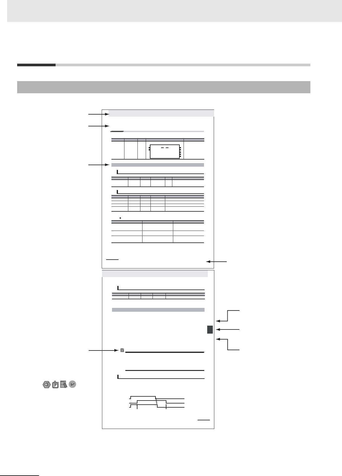
The following page structure is used in this manual.
Page Structure
Manual name
Special information
Icons indicate
precautions, additional
information, or reference
information.
Note: This page is for illustration only. It does not represent a specific page in this manual.
Level-1 section heading
Level-2 section heading
Level-1 section number
Level-3 section heading
The level-1 section number
is given.
The level-2 section heading
is given.
The level-3 section heading
is given.
3 Axis Command Instructions
3-2
NJ-series Motion Control Instructions Reference Manual (W508)
MC_Power
The MC_Power instruction makes a Servo Drive ready to operate.
*Refer to A-1 Error Codes.
Output Variable Update Timing
Instruction Name FB/FUN Graphic expression ST expression
MC_Power Power Servo FB MC_Power_instance (
Axis :=parameter,
Enable :=parameter,
Status =>parameter,
Busy =>parameter,
Error =>parameter,
ErrorID =>parameter
);
Variables
Input Variables
Name Meaning Data type Valid range Default Description
Enable Enable BOOL TRUE or FALSE FALSE The device is ready for operation when
Enable is TRUE, and not ready when it is
FAL SE.
Output Variables
Name Meaning Data type Valid range Description
Status Servo ON BOOL TRUE or FALSE TRUE when the device is ready for operation.
Busy Executing BOOL TRUE or FALSE TRUE when the instruction is acknowledged.
Error Error BOOL TRUE or FALSE TRUE while there is an error.
ErrorID Error Code WORD
*
Contains the error code when an error occurs.
A value of 16#0000 indicates normal execution.
Name Timing for changing to TRUE Timing for changing to FALSE
Status When the specified axis becomes
ready for operation.
• When operation ready status for the
specified axis is cleared.
• When Error changes to TRUE.
Busy When Enable changes to TRUE. • When Enable changes to FALSE.
• When Error changes to TRUE.
Error When there is an error in the execution
conditions or input parameters for the
instruction.
When the error is cleared.
MC_Power_instance
Error
Axis Axis
Enable Status
Busy
MC_Power
ErrorID
3-3
3 Axis Command Instructions
NJ-series Motion Control Instructions Reference Manual (W508)
rewoP_CM
3
noitcnuF
* Specify an Axis Variable that was created in the Axis Basic Settings of the Sysmac Studio. (The default axis variable names
are MC_Axis***.)
• When Enable changes to TRUE, the axis specified by Axis is made ready to operate.
You can control the axis when it is ready to operate.
• When Enable changes to FALSE, the ready status is cleared for the axis specified by Axis.
You cannot control the axis after the ready status is cleared because it will not acknowledge opera-
tion commands. Also, an error occurs if a motion command is executed for an axis for which the
ready status is cleared. You can execute the MC_Power (Power Servo) and MC_Reset (Reset Axis
Error) instructions even for axes that are not ready.
• You can use this instruction to disable the operation of axes while they are in motion. In this case,
CommandAborted will change to TRUE. Output of the operation command will stop and the axis will
not longer be ready for operation.
• If home is not defined for a Servomotor with an absolute encoder, compensation is performed using
the absolute encoder home offset to define home when the axis is ready to operate.
For details on the absolute encoder home offset, refer to the NJ-series CPU Unit Motion Control
User’s Manual (Cat. No. W507).
Precautions for Correct UsePrecautions for Correct Use
• You can use this instruction for servo axes and virtual servo axes. If the instruction is used for
encoder axes or virtual encoder axes, an error will occur.
• Executing this Instruction for the Master Axis of Synchronized Control
When master axis operation is disabled for a vertical axis, the position of the master axis may
change rapidly. This may cause the motion of the slave axis to change rapidly. Take suitable
measures to prevent the slave axis from moving rapidly, such as applying a brake to the mas-
ter axis or leaving master axis operation enabled until after synchronized control is completed.
• When Enable changes to TRUE, Busy (Executing) changes to TRUE to indicate that the instruction
was acknowledged.
• After the axis becomes ready for operation, Status (Servo ON) changes to TRUE.
• When Enable changes to FALSE, Busy (Executing) changes to FALSE. Status (Servo ON) changes
to FALSE when ready status is cleared. Status (Servo ON) outputs the axis ready status regardless
of whether Enable is TRUE or FALSE.
In-Out Variables
Name Meaning Data type Valid range Description
Axis Axis _sAXIS_REF ---
Specify the axis.
*
Function
Timing Charts
Enable
Status
Busy
The specified axis becomes
ready for operation.
Ready status is cleared for the
specified axis.
Level-2 section heading
Level-3 section heading

5
Manual Structure
NJ/NX-series Motion Control Instructions Reference Manual (W508)
Special information in this manual is classified as follows:
Note References are provided to more detailed or related information.
Special Information
Precautions for Safe Use
Precautions on what to do and what not to do to ensure safe usage of the product.
Precautions for Correct Use
Precautions on what to do and what not to do to ensure proper operation and performance.
Additional Information
Additional information to read as required.
This information is provided to increase understanding or make operation easier.
Version Information
Information on differences in specifications and functionality for CPU Units with different unit versions
and for different versions of the Sysmac Studio are given.

Manual Structure
6
NJ/NX-series Motion Control Instructions Reference Manual (W508)

7
Sections in this Manual
NJ/NX-series Motion Control Instructions Reference Manual (W508)
Sections in this Manual
1
2
3
4
5
A
I
1
2
3
4
5
A
I
Introduction to Motion Control Instructions
Variables and Instructions
Axis Command Instructions
Axes Group Instructions
Common Command Instructions
Appendices
Index

Sections in this Manual
8
NJ/NX-series Motion Control Instructions Reference Manual (W508)

9
NJ/NX-series Motion Control Instructions Reference Manual (W508)
CONTENTS
CONTENTS
Introduction............................................................................................................... 1
Relevant Manuals...................................................................................................... 2
Manual Structure ...................................................................................................... 4
Sections in this Manual............................................................................................ 7
Terms and Conditions Agreement ........................................................................ 15
Safety Precautions ................................................................................................. 17
Precautions for Safe Use ....................................................................................... 18
Precautions for Correct Use .................................................................................. 19
Regulations and Standards ................................................................................... 20
Versions................................................................................................................... 22
Related Manuals ..................................................................................................... 26
Revision History ..................................................................................................... 29
Section 1 Introduction to Motion Control Instructions
1-1 Motion Control Instructions.................................................................................................... 1-2
Function Blocks for PLCopen® Motion Control . . . . . . . . . . . . . . . . . . . . . . . . . . . . . . . . . . . . . . . . . . . . 1-2
Overview of Motion Control Instructions . . . . . . . . . . . . . . . . . . . . . . . . . . . . . . . . . . . . . . . . . . . . . . . . . . 1-3
Precautions for Master and Auxiliary Axes in Synchronized Control . . . . . . . . . . . . . . . . . . . . . . . . . . . . 1-6
1-2 Basic Information on Motion Control Instructions............................................................... 1-8
Motion Control Instruction Names . . . . . . . . . . . . . . . . . . . . . . . . . . . . . . . . . . . . . . . . . . . . . . . . . . . . . . 1-8
Languages for Motion Control Instructions . . . . . . . . . . . . . . . . . . . . . . . . . . . . . . . . . . . . . . . . . . . . . . . . 1-8
Motion Control Instruction Locations . . . . . . . . . . . . . . . . . . . . . . . . . . . . . . . . . . . . . . . . . . . . . . . . . . . . 1-9
Multi-execution of Motion Control Instructions . . . . . . . . . . . . . . . . . . . . . . . . . . . . . . . . . . . . . . . . . . . . 1-17
Online Editing of Motion Control Instructions . . . . . . . . . . . . . . . . . . . . . . . . . . . . . . . . . . . . . . . . . . . . . 1-18
Changes in the Operating Mode of the CPU Unit . . . . . . . . . . . . . . . . . . . . . . . . . . . . . . . . . . . . . . . . . . 1-18
Section 2 Variables and Instructions
2-1 Variables ................................................................................................................................... 2-2
MC Common Variables . . . . . . . . . . . . . . . . . . . . . . . . . . . . . . . . . . . . . . . . . . . . . . . . . . . . . . . . . . . . . . 2-3
Axis Variables . . . . . . . . . . . . . . . . . . . . . . . . . . . . . . . . . . . . . . . . . . . . . . . . . . . . . . . . . . . . . . . . . . . . . . 2-4
Axes Group Variables . . . . . . . . . . . . . . . . . . . . . . . . . . . . . . . . . . . . . . . . . . . . . . . . . . . . . . . . . . . . . . . . 2-9
Input Variables for Motion Control Instructions . . . . . . . . . . . . . . . . . . . . . . . . . . . . . . . . . . . . . . . . . . . . 2-12
Output Variables for Motion Control Instructions . . . . . . . . . . . . . . . . . . . . . . . . . . . . . . . . . . . . . . . . . . 2-25
In-Out Variables for Motion Control Instructions . . . . . . . . . . . . . . . . . . . . . . . . . . . . . . . . . . . . . . . . . . . 2-29
2-2 Instructions ............................................................................................................................ 2-31
Common Commands . . . . . . . . . . . . . . . . . . . . . . . . . . . . . . . . . . . . . . . . . . . . . . . . . . . . . . . . . . . . . . . 2-31
Axis Commands . . . . . . . . . . . . . . . . . . . . . . . . . . . . . . . . . . . . . . . . . . . . . . . . . . . . . . . . . . . . . . . . . . . 2-32
Axes Group Commands . . . . . . . . . . . . . . . . . . . . . . . . . . . . . . . . . . . . . . . . . . . . . . . . . . . . . . . . . . . . . 2-33
2-3 PDO Mapping ......................................................................................................................... 2-35
Required Objects . . . . . . . . . . . . . . . . . . . . . . . . . . . . . . . . . . . . . . . . . . . . . . . . . . . . . . . . . . . . . . . . . . 2-35
Objects Required for Specific Instructions . . . . . . . . . . . . . . . . . . . . . . . . . . . . . . . . . . . . . . . . . . . . . . . 2-37

10
NJ/NX-series Motion Control Instructions Reference Manual (W508)
CONTENTS
Section 3 Axis Command Instructions
MC_Power . . . . . . . . . . . . . . . . . . . . . . . . . . . . . . . . . . . . . . . . . . . . . . . . . . . . . . . . . . . . . . . . . . . . 3-3
Variables . . . . . . . . . . . . . . . . . . . . . . . . . . . . . . . . . . . . . . . . . . . . . . . . . . . . . . . . . . . . . . . . . . . . . . . . . . 3-3
Function . . . . . . . . . . . . . . . . . . . . . . . . . . . . . . . . . . . . . . . . . . . . . . . . . . . . . . . . . . . . . . . . . . . . . . . . . .3-4
MC_MoveJog . . . . . . . . . . . . . . . . . . . . . . . . . . . . . . . . . . . . . . . . . . . . . . . . . . . . . . . . . . . . . . . . . . 3-8
Variables . . . . . . . . . . . . . . . . . . . . . . . . . . . . . . . . . . . . . . . . . . . . . . . . . . . . . . . . . . . . . . . . . . . . . . . . . . 3-8
Function . . . . . . . . . . . . . . . . . . . . . . . . . . . . . . . . . . . . . . . . . . . . . . . . . . . . . . . . . . . . . . . . . . . . . . . . . .3-9
MC_Home . . . . . . . . . . . . . . . . . . . . . . . . . . . . . . . . . . . . . . . . . . . . . . . . . . . . . . . . . . . . . . . . . . . . 3-16
Variables . . . . . . . . . . . . . . . . . . . . . . . . . . . . . . . . . . . . . . . . . . . . . . . . . . . . . . . . . . . . . . . . . . . . . . . . . 3-16
Function . . . . . . . . . . . . . . . . . . . . . . . . . . . . . . . . . . . . . . . . . . . . . . . . . . . . . . . . . . . . . . . . . . . . . . . . . 3-17
MC_HomeWithParameter . . . . . . . . . . . . . . . . . . . . . . . . . . . . . . . . . . . . . . . . . . . . . . . . . . . . . . . 3-38
Variables . . . . . . . . . . . . . . . . . . . . . . . . . . . . . . . . . . . . . . . . . . . . . . . . . . . . . . . . . . . . . . . . . . . . . . . . . 3-38
Function . . . . . . . . . . . . . . . . . . . . . . . . . . . . . . . . . . . . . . . . . . . . . . . . . . . . . . . . . . . . . . . . . . . . . . . . . 3-41
MC_Move . . . . . . . . . . . . . . . . . . . . . . . . . . . . . . . . . . . . . . . . . . . . . . . . . . . . . . . . . . . . . . . . . . . . 3-44
Variables . . . . . . . . . . . . . . . . . . . . . . . . . . . . . . . . . . . . . . . . . . . . . . . . . . . . . . . . . . . . . . . . . . . . . . . . . 3-44
Function . . . . . . . . . . . . . . . . . . . . . . . . . . . . . . . . . . . . . . . . . . . . . . . . . . . . . . . . . . . . . . . . . . . . . . . . . 3-46
MC_MoveAbsolute . . . . . . . . . . . . . . . . . . . . . . . . . . . . . . . . . . . . . . . . . . . . . . . . . . . . . . . . . . . . . 3-49
Variables . . . . . . . . . . . . . . . . . . . . . . . . . . . . . . . . . . . . . . . . . . . . . . . . . . . . . . . . . . . . . . . . . . . . . . . . . 3-49
Function . . . . . . . . . . . . . . . . . . . . . . . . . . . . . . . . . . . . . . . . . . . . . . . . . . . . . . . . . . . . . . . . . . . . . . . . . 3-51
Sample Programming 1 . . . . . . . . . . . . . . . . . . . . . . . . . . . . . . . . . . . . . . . . . . . . . . . . . . . . . . . . . . . . . .3-59
Sample Programming 2 . . . . . . . . . . . . . . . . . . . . . . . . . . . . . . . . . . . . . . . . . . . . . . . . . . . . . . . . . . . . . .3-67
MC_MoveRelative . . . . . . . . . . . . . . . . . . . . . . . . . . . . . . . . . . . . . . . . . . . . . . . . . . . . . . . . . . . . . 3-76
Variables . . . . . . . . . . . . . . . . . . . . . . . . . . . . . . . . . . . . . . . . . . . . . . . . . . . . . . . . . . . . . . . . . . . . . . . . . 3-76
Function . . . . . . . . . . . . . . . . . . . . . . . . . . . . . . . . . . . . . . . . . . . . . . . . . . . . . . . . . . . . . . . . . . . . . . . . . 3-78
MC_MoveVelocity . . . . . . . . . . . . . . . . . . . . . . . . . . . . . . . . . . . . . . . . . . . . . . . . . . . . . . . . . . . . . 3-83
Variables . . . . . . . . . . . . . . . . . . . . . . . . . . . . . . . . . . . . . . . . . . . . . . . . . . . . . . . . . . . . . . . . . . . . . . . . . 3-83
Function . . . . . . . . . . . . . . . . . . . . . . . . . . . . . . . . . . . . . . . . . . . . . . . . . . . . . . . . . . . . . . . . . . . . . . . . . 3-85
Sample Programming . . . . . . . . . . . . . . . . . . . . . . . . . . . . . . . . . . . . . . . . . . . . . . . . . . . . . . . . . . . . . . . 3-90
MC_MoveZeroPosition . . . . . . . . . . . . . . . . . . . . . . . . . . . . . . . . . . . . . . . . . . . . . . . . . . . . . . . . . 3-98
Variables . . . . . . . . . . . . . . . . . . . . . . . . . . . . . . . . . . . . . . . . . . . . . . . . . . . . . . . . . . . . . . . . . . . . . . . . . 3-98
Function . . . . . . . . . . . . . . . . . . . . . . . . . . . . . . . . . . . . . . . . . . . . . . . . . . . . . . . . . . . . . . . . . . . . . . . . 3-100
MC_MoveFeed . . . . . . . . . . . . . . . . . . . . . . . . . . . . . . . . . . . . . . . . . . . . . . . . . . . . . . . . . . . . . . . 3-105
Variables . . . . . . . . . . . . . . . . . . . . . . . . . . . . . . . . . . . . . . . . . . . . . . . . . . . . . . . . . . . . . . . . . . . . . . . . 3-106
Function . . . . . . . . . . . . . . . . . . . . . . . . . . . . . . . . . . . . . . . . . . . . . . . . . . . . . . . . . . . . . . . . . . . . . . . . 3-109
Sample Programming . . . . . . . . . . . . . . . . . . . . . . . . . . . . . . . . . . . . . . . . . . . . . . . . . . . . . . . . . . . . . . 3-122
MC_Stop . . . . . . . . . . . . . . . . . . . . . . . . . . . . . . . . . . . . . . . . . . . . . . . . . . . . . . . . . . . . . . . . . . . . 3-133
Variables . . . . . . . . . . . . . . . . . . . . . . . . . . . . . . . . . . . . . . . . . . . . . . . . . . . . . . . . . . . . . . . . . . . . . . . . 3-133
Function . . . . . . . . . . . . . . . . . . . . . . . . . . . . . . . . . . . . . . . . . . . . . . . . . . . . . . . . . . . . . . . . . . . . . . . . 3-134
MC_ImmediateStop . . . . . . . . . . . . . . . . . . . . . . . . . . . . . . . . . . . . . . . . . . . . . . . . . . . . . . . . . . . 3-142
Variables . . . . . . . . . . . . . . . . . . . . . . . . . . . . . . . . . . . . . . . . . . . . . . . . . . . . . . . . . . . . . . . . . . . . . . . . 3-142
Function . . . . . . . . . . . . . . . . . . . . . . . . . . . . . . . . . . . . . . . . . . . . . . . . . . . . . . . . . . . . . . . . . . . . . . . . 3-143
MC_SetPosition . . . . . . . . . . . . . . . . . . . . . . . . . . . . . . . . . . . . . . . . . . . . . . . . . . . . . . . . . . . . . . 3-147
Variables . . . . . . . . . . . . . . . . . . . . . . . . . . . . . . . . . . . . . . . . . . . . . . . . . . . . . . . . . . . . . . . . . . . . . . . . 3-147
Function . . . . . . . . . . . . . . . . . . . . . . . . . . . . . . . . . . . . . . . . . . . . . . . . . . . . . . . . . . . . . . . . . . . . . . . . 3-148
MC_SetOverride . . . . . . . . . . . . . . . . . . . . . . . . . . . . . . . . . . . . . . . . . . . . . . . . . . . . . . . . . . . . . . 3-153
Variables . . . . . . . . . . . . . . . . . . . . . . . . . . . . . . . . . . . . . . . . . . . . . . . . . . . . . . . . . . . . . . . . . . . . . . . . 3-153
Function . . . . . . . . . . . . . . . . . . . . . . . . . . . . . . . . . . . . . . . . . . . . . . . . . . . . . . . . . . . . . . . . . . . . . . . . 3-154
MC_ResetFollowingError . . . . . . . . . . . . . . . . . . . . . . . . . . . . . . . . . . . . . . . . . . . . . . . . . . . . . . 3-158
Variables . . . . . . . . . . . . . . . . . . . . . . . . . . . . . . . . . . . . . . . . . . . . . . . . . . . . . . . . . . . . . . . . . . . . . . . . 3-158
Function . . . . . . . . . . . . . . . . . . . . . . . . . . . . . . . . . . . . . . . . . . . . . . . . . . . . . . . . . . . . . . . . . . . . . . . . 3-159
MC_CamIn . . . . . . . . . . . . . . . . . . . . . . . . . . . . . . . . . . . . . . . . . . . . . . . . . . . . . . . . . . . . . . . . . . 3-165
Variables . . . . . . . . . . . . . . . . . . . . . . . . . . . . . . . . . . . . . . . . . . . . . . . . . . . . . . . . . . . . . . . . . . . . . . . . 3-165
Function . . . . . . . . . . . . . . . . . . . . . . . . . . . . . . . . . . . . . . . . . . . . . . . . . . . . . . . . . . . . . . . . . . . . . . . . 3-169
Sample Programming 1 . . . . . . . . . . . . . . . . . . . . . . . . . . . . . . . . . . . . . . . . . . . . . . . . . . . . . . . . . . . . .3-192
Sample Programming 2 . . . . . . . . . . . . . . . . . . . . . . . . . . . . . . . . . . . . . . . . . . . . . . . . . . . . . . . . . . . . .3-203
MC_CamOut . . . . . . . . . . . . . . . . . . . . . . . . . . . . . . . . . . . . . . . . . . . . . . . . . . . . . . . . . . . . . . . . . 3-219
Variables . . . . . . . . . . . . . . . . . . . . . . . . . . . . . . . . . . . . . . . . . . . . . . . . . . . . . . . . . . . . . . . . . . . . . . . . 3-219
Function . . . . . . . . . . . . . . . . . . . . . . . . . . . . . . . . . . . . . . . . . . . . . . . . . . . . . . . . . . . . . . . . . . . . . . . . 3-220
MC_GearIn . . . . . . . . . . . . . . . . . . . . . . . . . . . . . . . . . . . . . . . . . . . . . . . . . . . . . . . . . . . . . . . . . . 3-224
Variables . . . . . . . . . . . . . . . . . . . . . . . . . . . . . . . . . . . . . . . . . . . . . . . . . . . . . . . . . . . . . . . . . . . . . . . . 3-224
Function . . . . . . . . . . . . . . . . . . . . . . . . . . . . . . . . . . . . . . . . . . . . . . . . . . . . . . . . . . . . . . . . . . . . . . . . 3-226
Sample Programming . . . . . . . . . . . . . . . . . . . . . . . . . . . . . . . . . . . . . . . . . . . . . . . . . . . . . . . . . . . . . . 3-233

11
NJ/NX-series Motion Control Instructions Reference Manual (W508)
CONTENTS
MC_GearInPos . . . . . . . . . . . . . . . . . . . . . . . . . . . . . . . . . . . . . . . . . . . . . . . . . . . . . . . . . . . . . . 3-243
Variables . . . . . . . . . . . . . . . . . . . . . . . . . . . . . . . . . . . . . . . . . . . . . . . . . . . . . . . . . . . . . . . . . . . . . . . . 3-243
Function . . . . . . . . . . . . . . . . . . . . . . . . . . . . . . . . . . . . . . . . . . . . . . . . . . . . . . . . . . . . . . . . . . . . . . . . 3-246
Sample Programming . . . . . . . . . . . . . . . . . . . . . . . . . . . . . . . . . . . . . . . . . . . . . . . . . . . . . . . . . . . . . . 3-254
MC_GearOut . . . . . . . . . . . . . . . . . . . . . . . . . . . . . . . . . . . . . . . . . . . . . . . . . . . . . . . . . . . . . . . . 3-264
Variables . . . . . . . . . . . . . . . . . . . . . . . . . . . . . . . . . . . . . . . . . . . . . . . . . . . . . . . . . . . . . . . . . . . . . . . . 3-264
Function . . . . . . . . . . . . . . . . . . . . . . . . . . . . . . . . . . . . . . . . . . . . . . . . . . . . . . . . . . . . . . . . . . . . . . . . 3-266
MC_MoveLink . . . . . . . . . . . . . . . . . . . . . . . . . . . . . . . . . . . . . . . . . . . . . . . . . . . . . . . . . . . . . . . 3-269
Variables . . . . . . . . . . . . . . . . . . . . . . . . . . . . . . . . . . . . . . . . . . . . . . . . . . . . . . . . . . . . . . . . . . . . . . . . 3-269
Function . . . . . . . . . . . . . . . . . . . . . . . . . . . . . . . . . . . . . . . . . . . . . . . . . . . . . . . . . . . . . . . . . . . . . . . . 3-272
Sample Programming . . . . . . . . . . . . . . . . . . . . . . . . . . . . . . . . . . . . . . . . . . . . . . . . . . . . . . . . . . . . . . 3-282
MC_CombineAxes . . . . . . . . . . . . . . . . . . . . . . . . . . . . . . . . . . . . . . . . . . . . . . . . . . . . . . . . . . . 3-292
Variables . . . . . . . . . . . . . . . . . . . . . . . . . . . . . . . . . . . . . . . . . . . . . . . . . . . . . . . . . . . . . . . . . . . . . . . . 3-292
Function . . . . . . . . . . . . . . . . . . . . . . . . . . . . . . . . . . . . . . . . . . . . . . . . . . . . . . . . . . . . . . . . . . . . . . . . 3-295
MC_Phasing . . . . . . . . . . . . . . . . . . . . . . . . . . . . . . . . . . . . . . . . . . . . . . . . . . . . . . . . . . . . . . . . 3-304
Variables . . . . . . . . . . . . . . . . . . . . . . . . . . . . . . . . . . . . . . . . . . . . . . . . . . . . . . . . . . . . . . . . . . . . . . . . 3-304
Function . . . . . . . . . . . . . . . . . . . . . . . . . . . . . . . . . . . . . . . . . . . . . . . . . . . . . . . . . . . . . . . . . . . . . . . . 3-306
MC_TorqueControl . . . . . . . . . . . . . . . . . . . . . . . . . . . . . . . . . . . . . . . . . . . . . . . . . . . . . . . . . . . 3-312
Variables . . . . . . . . . . . . . . . . . . . . . . . . . . . . . . . . . . . . . . . . . . . . . . . . . . . . . . . . . . . . . . . . . . . . . . . . 3-312
Function . . . . . . . . . . . . . . . . . . . . . . . . . . . . . . . . . . . . . . . . . . . . . . . . . . . . . . . . . . . . . . . . . . . . . . . . 3-314
MC_SetTorqueLimit . . . . . . . . . . . . . . . . . . . . . . . . . . . . . . . . . . . . . . . . . . . . . . . . . . . . . . . . . . 3-323
Variables . . . . . . . . . . . . . . . . . . . . . . . . . . . . . . . . . . . . . . . . . . . . . . . . . . . . . . . . . . . . . . . . . . . . . . . . 3-323
Function . . . . . . . . . . . . . . . . . . . . . . . . . . . . . . . . . . . . . . . . . . . . . . . . . . . . . . . . . . . . . . . . . . . . . . . . 3-324
MC_ZoneSwitch . . . . . . . . . . . . . . . . . . . . . . . . . . . . . . . . . . . . . . . . . . . . . . . . . . . . . . . . . . . . . 3-330
Variables . . . . . . . . . . . . . . . . . . . . . . . . . . . . . . . . . . . . . . . . . . . . . . . . . . . . . . . . . . . . . . . . . . . . . . . . 3-330
Function . . . . . . . . . . . . . . . . . . . . . . . . . . . . . . . . . . . . . . . . . . . . . . . . . . . . . . . . . . . . . . . . . . . . . . . . 3-332
MC_TouchProbe . . . . . . . . . . . . . . . . . . . . . . . . . . . . . . . . . . . . . . . . . . . . . . . . . . . . . . . . . . . . . 3-336
Variables . . . . . . . . . . . . . . . . . . . . . . . . . . . . . . . . . . . . . . . . . . . . . . . . . . . . . . . . . . . . . . . . . . . . . . . . 3-336
Function . . . . . . . . . . . . . . . . . . . . . . . . . . . . . . . . . . . . . . . . . . . . . . . . . . . . . . . . . . . . . . . . . . . . . . . . 3-339
Sample Programming . . . . . . . . . . . . . . . . . . . . . . . . . . . . . . . . . . . . . . . . . . . . . . . . . . . . . . . . . . . . . . 3-351
MC_AbortTrigger . . . . . . . . . . . . . . . . . . . . . . . . . . . . . . . . . . . . . . . . . . . . . . . . . . . . . . . . . . . . 3-358
Variables . . . . . . . . . . . . . . . . . . . . . . . . . . . . . . . . . . . . . . . . . . . . . . . . . . . . . . . . . . . . . . . . . . . . . . . . 3-358
Function . . . . . . . . . . . . . . . . . . . . . . . . . . . . . . . . . . . . . . . . . . . . . . . . . . . . . . . . . . . . . . . . . . . . . . . . 3-360
MC_AxesObserve . . . . . . . . . . . . . . . . . . . . . . . . . . . . . . . . . . . . . . . . . . . . . . . . . . . . . . . . . . . . 3-363
Variables . . . . . . . . . . . . . . . . . . . . . . . . . . . . . . . . . . . . . . . . . . . . . . . . . . . . . . . . . . . . . . . . . . . . . . . . 3-363
Function . . . . . . . . . . . . . . . . . . . . . . . . . . . . . . . . . . . . . . . . . . . . . . . . . . . . . . . . . . . . . . . . . . . . . . . . 3-365
MC_SyncMoveVelocity . . . . . . . . . . . . . . . . . . . . . . . . . . . . . . . . . . . . . . . . . . . . . . . . . . . . . . . . 3-369
Variables . . . . . . . . . . . . . . . . . . . . . . . . . . . . . . . . . . . . . . . . . . . . . . . . . . . . . . . . . . . . . . . . . . . . . . . . 3-369
Function . . . . . . . . . . . . . . . . . . . . . . . . . . . . . . . . . . . . . . . . . . . . . . . . . . . . . . . . . . . . . . . . . . . . . . . . 3-371
MC_SyncMoveAbsolute . . . . . . . . . . . . . . . . . . . . . . . . . . . . . . . . . . . . . . . . . . . . . . . . . . . . . . . 3-379
Variables . . . . . . . . . . . . . . . . . . . . . . . . . . . . . . . . . . . . . . . . . . . . . . . . . . . . . . . . . . . . . . . . . . . . . . . . 3-379
Function . . . . . . . . . . . . . . . . . . . . . . . . . . . . . . . . . . . . . . . . . . . . . . . . . . . . . . . . . . . . . . . . . . . . . . . . 3-381
MC_Reset . . . . . . . . . . . . . . . . . . . . . . . . . . . . . . . . . . . . . . . . . . . . . . . . . . . . . . . . . . . . . . . . . . 3-386
Variables . . . . . . . . . . . . . . . . . . . . . . . . . . . . . . . . . . . . . . . . . . . . . . . . . . . . . . . . . . . . . . . . . . . . . . . . 3-386
Function . . . . . . . . . . . . . . . . . . . . . . . . . . . . . . . . . . . . . . . . . . . . . . . . . . . . . . . . . . . . . . . . . . . . . . . . 3-387
MC_ChangeAxisUse . . . . . . . . . . . . . . . . . . . . . . . . . . . . . . . . . . . . . . . . . . . . . . . . . . . . . . . . . . 3-390
Variables . . . . . . . . . . . . . . . . . . . . . . . . . . . . . . . . . . . . . . . . . . . . . . . . . . . . . . . . . . . . . . . . . . . . . . . . 3-390
Function . . . . . . . . . . . . . . . . . . . . . . . . . . . . . . . . . . . . . . . . . . . . . . . . . . . . . . . . . . . . . . . . . . . . . . . . 3-391
MC_DigitalCamSwitch . . . . . . . . . . . . . . . . . . . . . . . . . . . . . . . . . . . . . . . . . . . . . . . . . . . . . . . . 3-394
Variables . . . . . . . . . . . . . . . . . . . . . . . . . . . . . . . . . . . . . . . . . . . . . . . . . . . . . . . . . . . . . . . . . . . . . . . . 3-395
Function . . . . . . . . . . . . . . . . . . . . . . . . . . . . . . . . . . . . . . . . . . . . . . . . . . . . . . . . . . . . . . . . . . . . . . . . 3-396
Sample Programming . . . . . . . . . . . . . . . . . . . . . . . . . . . . . . . . . . . . . . . . . . . . . . . . . . . . . . . . . . . . . . 3-406
MC_TimeStampToPos . . . . . . . . . . . . . . . . . . . . . . . . . . . . . . . . . . . . . . . . . . . . . . . . . . . . . . . . 3-413
Variables . . . . . . . . . . . . . . . . . . . . . . . . . . . . . . . . . . . . . . . . . . . . . . . . . . . . . . . . . . . . . . . . . . . . . . . . 3-413
Function . . . . . . . . . . . . . . . . . . . . . . . . . . . . . . . . . . . . . . . . . . . . . . . . . . . . . . . . . . . . . . . . . . . . . . . . 3-414
Sample Programming . . . . . . . . . . . . . . . . . . . . . . . . . . . . . . . . . . . . . . . . . . . . . . . . . . . . . . . . . . . . . . 3-417
MC_PeriodicSyncVariables . . . . . . . . . . . . . . . . . . . . . . . . . . . . . . . . . . . . . . . . . . . . . . . . . . . . 3-425
Variables . . . . . . . . . . . . . . . . . . . . . . . . . . . . . . . . . . . . . . . . . . . . . . . . . . . . . . . . . . . . . . . . . . . . . . . . 3-425
Function . . . . . . . . . . . . . . . . . . . . . . . . . . . . . . . . . . . . . . . . . . . . . . . . . . . . . . . . . . . . . . . . . . . . . . . . 3-426
Sample Programming . . . . . . . . . . . . . . . . . . . . . . . . . . . . . . . . . . . . . . . . . . . . . . . . . . . . . . . . . . . . . . 3-430
MC_SyncOffsetPosition . . . . . . . . . . . . . . . . . . . . . . . . . . . . . . . . . . . . . . . . . . . . . . . . . . . . . . . 3-433
Variables . . . . . . . . . . . . . . . . . . . . . . . . . . . . . . . . . . . . . . . . . . . . . . . . . . . . . . . . . . . . . . . . . . . . . . . . 3-433
Function . . . . . . . . . . . . . . . . . . . . . . . . . . . . . . . . . . . . . . . . . . . . . . . . . . . . . . . . . . . . . . . . . . . . . . . . 3-435

12
NJ/NX-series Motion Control Instructions Reference Manual (W508)
CONTENTS
Section 4 Axes Group Instructions
MC_GroupEnable . . . . . . . . . . . . . . . . . . . . . . . . . . . . . . . . . . . . . . . . . . . . . . . . . . . . . . . . . . . . . . . 4-2
Variables . . . . . . . . . . . . . . . . . . . . . . . . . . . . . . . . . . . . . . . . . . . . . . . . . . . . . . . . . . . . . . . . . . . . . . . . . . 4-2
Function . . . . . . . . . . . . . . . . . . . . . . . . . . . . . . . . . . . . . . . . . . . . . . . . . . . . . . . . . . . . . . . . . . . . . . . . . .4-3
MC_GroupDisable . . . . . . . . . . . . . . . . . . . . . . . . . . . . . . . . . . . . . . . . . . . . . . . . . . . . . . . . . . . . . . 4-6
Variables . . . . . . . . . . . . . . . . . . . . . . . . . . . . . . . . . . . . . . . . . . . . . . . . . . . . . . . . . . . . . . . . . . . . . . . . . . 4-6
Function . . . . . . . . . . . . . . . . . . . . . . . . . . . . . . . . . . . . . . . . . . . . . . . . . . . . . . . . . . . . . . . . . . . . . . . . . .4-7
MC_MoveLinear . . . . . . . . . . . . . . . . . . . . . . . . . . . . . . . . . . . . . . . . . . . . . . . . . . . . . . . . . . . . . . . 4-10
Variables . . . . . . . . . . . . . . . . . . . . . . . . . . . . . . . . . . . . . . . . . . . . . . . . . . . . . . . . . . . . . . . . . . . . . . . . . 4-10
Function . . . . . . . . . . . . . . . . . . . . . . . . . . . . . . . . . . . . . . . . . . . . . . . . . . . . . . . . . . . . . . . . . . . . . . . . . 4-12
Sample Programming . . . . . . . . . . . . . . . . . . . . . . . . . . . . . . . . . . . . . . . . . . . . . . . . . . . . . . . . . . . . . . . 4-23
MC_MoveLinearAbsolute . . . . . . . . . . . . . . . . . . . . . . . . . . . . . . . . . . . . . . . . . . . . . . . . . . . . . . . 4-36
Variables . . . . . . . . . . . . . . . . . . . . . . . . . . . . . . . . . . . . . . . . . . . . . . . . . . . . . . . . . . . . . . . . . . . . . . . . . 4-36
Function . . . . . . . . . . . . . . . . . . . . . . . . . . . . . . . . . . . . . . . . . . . . . . . . . . . . . . . . . . . . . . . . . . . . . . . . . 4-38
MC_MoveLinearRelative . . . . . . . . . . . . . . . . . . . . . . . . . . . . . . . . . . . . . . . . . . . . . . . . . . . . . . . . 4-39
Variables . . . . . . . . . . . . . . . . . . . . . . . . . . . . . . . . . . . . . . . . . . . . . . . . . . . . . . . . . . . . . . . . . . . . . . . . . 4-39
Function . . . . . . . . . . . . . . . . . . . . . . . . . . . . . . . . . . . . . . . . . . . . . . . . . . . . . . . . . . . . . . . . . . . . . . . . . 4-41
MC_MoveCircular2D . . . . . . . . . . . . . . . . . . . . . . . . . . . . . . . . . . . . . . . . . . . . . . . . . . . . . . . . . . . 4-42
Variables . . . . . . . . . . . . . . . . . . . . . . . . . . . . . . . . . . . . . . . . . . . . . . . . . . . . . . . . . . . . . . . . . . . . . . . . . 4-42
Function . . . . . . . . . . . . . . . . . . . . . . . . . . . . . . . . . . . . . . . . . . . . . . . . . . . . . . . . . . . . . . . . . . . . . . . . . 4-45
Sample Programming . . . . . . . . . . . . . . . . . . . . . . . . . . . . . . . . . . . . . . . . . . . . . . . . . . . . . . . . . . . . . . . 4-54
MC_GroupStop . . . . . . . . . . . . . . . . . . . . . . . . . . . . . . . . . . . . . . . . . . . . . . . . . . . . . . . . . . . . . . . 4-66
Variables . . . . . . . . . . . . . . . . . . . . . . . . . . . . . . . . . . . . . . . . . . . . . . . . . . . . . . . . . . . . . . . . . . . . . . . . . 4-66
Function . . . . . . . . . . . . . . . . . . . . . . . . . . . . . . . . . . . . . . . . . . . . . . . . . . . . . . . . . . . . . . . . . . . . . . . . . 4-68
MC_GroupImmediateStop . . . . . . . . . . . . . . . . . . . . . . . . . . . . . . . . . . . . . . . . . . . . . . . . . . . . . . . 4-75
Variables . . . . . . . . . . . . . . . . . . . . . . . . . . . . . . . . . . . . . . . . . . . . . . . . . . . . . . . . . . . . . . . . . . . . . . . . . 4-75
Function . . . . . . . . . . . . . . . . . . . . . . . . . . . . . . . . . . . . . . . . . . . . . . . . . . . . . . . . . . . . . . . . . . . . . . . . . 4-76
MC_GroupSetOverride . . . . . . . . . . . . . . . . . . . . . . . . . . . . . . . . . . . . . . . . . . . . . . . . . . . . . . . . . 4-79
Variables . . . . . . . . . . . . . . . . . . . . . . . . . . . . . . . . . . . . . . . . . . . . . . . . . . . . . . . . . . . . . . . . . . . . . . . . . 4-79
Function . . . . . . . . . . . . . . . . . . . . . . . . . . . . . . . . . . . . . . . . . . . . . . . . . . . . . . . . . . . . . . . . . . . . . . . . . 4-80
MC_GroupReadPosition . . . . . . . . . . . . . . . . . . . . . . . . . . . . . . . . . . . . . . . . . . . . . . . . . . . . . . . . 4-83
Variables . . . . . . . . . . . . . . . . . . . . . . . . . . . . . . . . . . . . . . . . . . . . . . . . . . . . . . . . . . . . . . . . . . . . . . . . . 4-83
Function . . . . . . . . . . . . . . . . . . . . . . . . . . . . . . . . . . . . . . . . . . . . . . . . . . . . . . . . . . . . . . . . . . . . . . . . . 4-85
MC_ChangeAxesInGroup . . . . . . . . . . . . . . . . . . . . . . . . . . . . . . . . . . . . . . . . . . . . . . . . . . . . . . . 4-87
Variables . . . . . . . . . . . . . . . . . . . . . . . . . . . . . . . . . . . . . . . . . . . . . . . . . . . . . . . . . . . . . . . . . . . . . . . . . 4-87
Function . . . . . . . . . . . . . . . . . . . . . . . . . . . . . . . . . . . . . . . . . . . . . . . . . . . . . . . . . . . . . . . . . . . . . . . . . 4-89
MC_GroupSyncMoveAbsolute . . . . . . . . . . . . . . . . . . . . . . . . . . . . . . . . . . . . . . . . . . . . . . . . . . . 4-91
Variables . . . . . . . . . . . . . . . . . . . . . . . . . . . . . . . . . . . . . . . . . . . . . . . . . . . . . . . . . . . . . . . . . . . . . . . . . 4-91
Function . . . . . . . . . . . . . . . . . . . . . . . . . . . . . . . . . . . . . . . . . . . . . . . . . . . . . . . . . . . . . . . . . . . . . . . . . 4-93
MC_GroupReset . . . . . . . . . . . . . . . . . . . . . . . . . . . . . . . . . . . . . . . . . . . . . . . . . . . . . . . . . . . . . . . 4-97
Variables . . . . . . . . . . . . . . . . . . . . . . . . . . . . . . . . . . . . . . . . . . . . . . . . . . . . . . . . . . . . . . . . . . . . . . . . . 4-97
Function . . . . . . . . . . . . . . . . . . . . . . . . . . . . . . . . . . . . . . . . . . . . . . . . . . . . . . . . . . . . . . . . . . . . . . . . . 4-98
Section 5 Common Command Instructions
MC_SetCamTableProperty . . . . . . . . . . . . . . . . . . . . . . . . . . . . . . . . . . . . . . . . . . . . . . . . . . . . . . . 5-2
Variables . . . . . . . . . . . . . . . . . . . . . . . . . . . . . . . . . . . . . . . . . . . . . . . . . . . . . . . . . . . . . . . . . . . . . . . . . . 5-2
Function . . . . . . . . . . . . . . . . . . . . . . . . . . . . . . . . . . . . . . . . . . . . . . . . . . . . . . . . . . . . . . . . . . . . . . . . . .5-3
MC_SaveCamTable . . . . . . . . . . . . . . . . . . . . . . . . . . . . . . . . . . . . . . . . . . . . . . . . . . . . . . . . . . . . . 5-8
Variables . . . . . . . . . . . . . . . . . . . . . . . . . . . . . . . . . . . . . . . . . . . . . . . . . . . . . . . . . . . . . . . . . . . . . . . . . . 5-8
Function . . . . . . . . . . . . . . . . . . . . . . . . . . . . . . . . . . . . . . . . . . . . . . . . . . . . . . . . . . . . . . . . . . . . . . . . . .5-9
MC_Write . . . . . . . . . . . . . . . . . . . . . . . . . . . . . . . . . . . . . . . . . . . . . . . . . . . . . . . . . . . . . . . . . . . . 5-12
Variables . . . . . . . . . . . . . . . . . . . . . . . . . . . . . . . . . . . . . . . . . . . . . . . . . . . . . . . . . . . . . . . . . . . . . . . . . 5-13
Function . . . . . . . . . . . . . . . . . . . . . . . . . . . . . . . . . . . . . . . . . . . . . . . . . . . . . . . . . . . . . . . . . . . . . . . . . 5-16
MC_GenerateCamTable . . . . . . . . . . . . . . . . . . . . . . . . . . . . . . . . . . . . . . . . . . . . . . . . . . . . . . . . 5-18
Variables . . . . . . . . . . . . . . . . . . . . . . . . . . . . . . . . . . . . . . . . . . . . . . . . . . . . . . . . . . . . . . . . . . . . . . . . . 5-18
Function . . . . . . . . . . . . . . . . . . . . . . . . . . . . . . . . . . . . . . . . . . . . . . . . . . . . . . . . . . . . . . . . . . . . . . . . . 5-21
Sample Programming . . . . . . . . . . . . . . . . . . . . . . . . . . . . . . . . . . . . . . . . . . . . . . . . . . . . . . . . . . . . . . . 5-35
MC_WriteAxisParameter . . . . . . . . . . . . . . . . . . . . . . . . . . . . . . . . . . . . . . . . . . . . . . . . . . . . . . . . 5-47
Variables . . . . . . . . . . . . . . . . . . . . . . . . . . . . . . . . . . . . . . . . . . . . . . . . . . . . . . . . . . . . . . . . . . . . . . . . . 5-47
Function . . . . . . . . . . . . . . . . . . . . . . . . . . . . . . . . . . . . . . . . . . . . . . . . . . . . . . . . . . . . . . . . . . . . . . . . . 5-49

13
NJ/NX-series Motion Control Instructions Reference Manual (W508)
CONTENTS
MC_ReadAxisParameter . . . . . . . . . . . . . . . . . . . . . . . . . . . . . . . . . . . . . . . . . . . . . . . . . . . . . . . 5-62
Variables . . . . . . . . . . . . . . . . . . . . . . . . . . . . . . . . . . . . . . . . . . . . . . . . . . . . . . . . . . . . . . . . . . . . . . . . . 5-62
Function . . . . . . . . . . . . . . . . . . . . . . . . . . . . . . . . . . . . . . . . . . . . . . . . . . . . . . . . . . . . . . . . . . . . . . . . . 5-64
Appendices
A-1 Error Codes..............................................................................................................................A-2
A-2 Error Code Details .................................................................................................................A-25
A-3 Instructions for Which Multi-execution Is Supported ......................................................A-108
A-3-1 Axis and Axes Group Status...................................................................................................A-109
A-3-2 State Transitions and Instructions for which Multi-execution Is Supported .............................A-111
A-4 Version Information .............................................................................................................A-117
Index

14
NJ/NX-series Motion Control Instructions Reference Manual (W508)
CONTENTS

15
Terms and Conditions Agreement
NJ/NX-series Motion Control Instructions Reference Manual (W508)
Terms and Conditions Agreement
Exclusive Warranty
Omron’s exclusive warranty is that the Products will be free from defects in materials and workman-
ship for a period of twelve months from the date of sale by Omron (or such other period expressed in
writing by Omron). Omron disclaims all other warranties, express or implied.
Limitations
OMRON MAKES NO WARRANTY OR REPRESENTATION, EXPRESS OR IMPLIED, ABOUT
NON-INFRINGEMENT, MERCHANTABILITY OR FITNESS FOR A PARTICULAR PURPOSE OF
THE PRODUCTS. BUYER ACKNOWLEDGES THAT IT ALONE HAS DETERMINED THAT THE
PRODUCTS WILL SUITABLY MEET THE REQUIREMENTS OF THEIR INTENDED USE.
Omron further disclaims all warranties and responsibility of any type for claims or expenses based
on infringement by the Products or otherwise of any intellectual property right.
Buyer Remedy
Omron’s sole obligation hereunder shall be, at Omron’s election, to (i) replace (in the form originally
shipped with Buyer responsible for labor charges for removal or replacement thereof) the non-com-
plying Product, (ii) repair the non-complying Product, or (iii) repay or credit Buyer an amount equal
to the purchase price of the non-complying Product; provided that in no event shall Omron be
responsible for warranty, repair, indemnity or any other claims or expenses regarding the Products
unless Omron’s analysis confirms that the Products were properly handled, stored, installed and
maintained and not subject to contamination, abuse, misuse or inappropriate modification. Return of
any Products by Buyer must be approved in writing by Omron before shipment. Omron Companies
shall not be liable for the suitability or unsuitability or the results from the use of Products in combi-
nation with any electrical or electronic components, circuits, system assemblies or any other materi-
als or substances or environments. Any advice, recommendations or information given orally or in
writing, are not to be construed as an amendment or addition to the above warranty.
See http://www.omron.com/global/ or contact your Omron representative for published information.
OMRON COMPANIES SHALL NOT BE LIABLE FOR SPECIAL, INDIRECT, INCIDENTAL, OR CON-
SEQUENTIAL DAMAGES, LOSS OF PROFITS OR PRODUCTION OR COMMERCIAL LOSS IN ANY
WAY CONNECTED WITH THE PRODUCTS, WHETHER SUCH CLAIM IS BASED IN CONTRACT,
WARRANTY, NEGLIGENCE OR STRICT LIABILITY.
Further, in no event shall liability of Omron Companies exceed the individual price of the Product on
which liability is asserted.
Warranty, Limitations of Liability
Warranties
Limitation on Liability; Etc

Terms and Conditions Agreement
16
NJ/NX-series Motion Control Instructions Reference Manual (W508)
Omron Companies shall not be responsible for conformity with any standards, codes or regulations
which apply to the combination of the Product in the Buyer’s application or use of the Product. At
Buyer’s request, Omron will provide applicable third party certification documents identifying ratings
and limitations of use which apply to the Product. This information by itself is not sufficient for a com-
plete determination of the suitability of the Product in combination with the end product, machine, sys-
tem, or other application or use. Buyer shall be solely responsible for determining appropriateness of
the particular Product with respect to Buyer’s application, product or system. Buyer shall take applica-
tion responsibility in all cases.
NEVER USE THE PRODUCT FOR AN APPLICATION INVOLVING SERIOUS RISK TO LIFE OR
PROPERTY WITHOUT ENSURING THAT THE SYSTEM AS A WHOLE HAS BEEN DESIGNED TO
ADDRESS THE RISKS, AND THAT THE OMRON PRODUCT(S) IS PROPERLY RATED AND
INSTALLED FOR THE INTENDED USE WITHIN THE OVERALL EQUIPMENT OR SYSTEM.
Omron Companies shall not be responsible for the user’s programming of a programmable Product, or
any consequence thereof.
Data presented in Omron Company websites, catalogs and other materials is provided as a guide for
the user in determining suitability and does not constitute a warranty. It may represent the result of
Omron’s test conditions, and the user must correlate it to actual application requirements. Actual perfor-
mance is subject to the Omron’s Warranty and Limitations of Liability.
Product specifications and accessories may be changed at any time based on improvements and other
reasons. It is our practice to change part numbers when published ratings or features are changed, or
when significant construction changes are made. However, some specifications of the Product may be
changed without any notice. When in doubt, special part numbers may be assigned to fix or establish
key specifications for your application. Please consult with your Omron’s representative at any time to
confirm actual specifications of purchased Product.
Information presented by Omron Companies has been checked and is believed to be accurate; how-
ever, no responsibility is assumed for clerical, typographical or proofreading errors or omissions.
Application Considerations
Suitability of Use
Programmable Products
Disclaimers
Performance Data
Change in Specifications
Errors and Omissions

17
Safety Precautions
NJ/NX-series Motion Control Instructions Reference Manual (W508)
Safety Precautions
Refer to the following manuals for safety precautions.
• NX-series CPU Unit Hardware User’s Manual (Cat. No. W535)
• NX-series NX1P2 CPU Unit Hardware User’s Manual (Cat. No. W578)
• NJ-series CPU Unit Hardware User’s Manual (Cat. No. W500)

Precautions for Safe Use
18
NJ/NX-series Motion Control Instructions Reference Manual (W508)
Precautions for Safe Use
Refer to the following manuals for precautions for safe use.
• NX-series CPU Unit Hardware User’s Manual (Cat. No. W535)
• NX-series NX1P2 CPU Unit Hardware User’s Manual (Cat. No. W578)
• NJ-series CPU Unit Hardware User’s Manual (Cat. No. W500)

19
Precautions for Correct Use
NJ/NX-series Motion Control Instructions Reference Manual (W508)
Precautions for Correct Use
Refer to the following manuals for precautions for correct use.
• NX-series CPU Unit Hardware User’s Manual (Cat. No. W535)
• NX-series NX1P2 CPU Unit Hardware User’s Manual (Cat. No. W578)
• NJ-series CPU Unit Hardware User’s Manual (Cat. No. W500)

Regulations and Standards
20
NJ/NX-series Motion Control Instructions Reference Manual (W508)
Regulations and Standards
• EMC Directives
• Low Voltage Directive
EMC Directive
OMRON devices that comply with EU Directives also conform to the related EMC standards so that
they can be more easily built into other devices or the overall machine. The actual products have
been checked for conformity to EMC standards.*
Whether the products conform to the standards in the system used by the customer, however, must
be checked by the customer. EMC-related performance of the OMRON devices that comply with EU
Directives will vary depending on the configuration, wiring, and other conditions of the equipment or
control panel on which the OMRON devices are installed. The customer must, therefore, perform
the final check to confirm that devices and the overall machine conform to EMC standards.
* Applicable EMC (Electromagnetic Compatibility) standards are as follows:
EMS (Electromagnetic Susceptibility): EN 61131-2
EMI (Electromagnetic Interference): EN 61131-2 (Radiated emission: 10-m regulations)
Low Voltage Directive
Always ensure that devices operating at voltages of 50 to 1,000 VAC and 75 to 1,500 VDC meet the
required safety standards. The applicable directive is EN61010-2-201.
Conformance to EU Directives
The NJ/NX-series Controllers comply with EU Directives. To ensure that the machine or device in
which the NJ/NX-series Controller is used complies with EU Directives, the Controller must be
installed as follows:
• The NJ/NX-series Controller must be installed within a control panel.
• You must use the power supply in SELV specifications for the DC power supplies connected to
DC Power Supply Units and I/O Units.
• NJ/NX-series Controllers that comply with EU Directives also conform to the Common Emission
Standard (EN 61000-6-4). Radiated emission characteristics (10-m regulations) may vary
depending on the configuration of the control panel used, other devices connected to the control
panel, wiring, and other conditions.
You must therefore confirm that the overall machine or equipment complies with EU Directives.
Conformance to EU Directives
Applicable Directives
Concepts

21
Regulations and Standards
NJ/NX-series Motion Control Instructions Reference Manual (W508)
Observe the following precaution if you use NX-series Units in Korea.
Class A Device (Broadcasting Communications Device for Office Use)
This device obtained EMC registration for office use (Class A), and it is intended to be used in places
other than homes.
Sellers and/or users need to take note of this.
The NJ/NX-series Controllers comply with the following shipbuilding standards. Applicability to the
shipbuilding standards is based on certain usage conditions. It may not be possible to use the prod-
uct in some locations. Contact your OMRON representative before attempting to use a Controller on
a ship.
• The NJ/NX-series Controller must be installed within a control panel.
• Gaps in the door to the control panel must be completely filled or covered with gaskets or other
material.
• The following noise filter must be connected to the power supply line.
Noise Filter
This product incorporates certain third party software. The license and copyright information associ-
ated with this software is available at http://www.fa.omron.co.jp/nj_info_e/.
Conformance to KC Standards
Conformance to Shipbuilding Standards
Usage Conditions for NK and LR Shipbuilding Standards
Manufacturer Model
Cosel Co., Ltd. TAH-06-683
Software Licenses and Copyrights

Versions
22
NJ/NX-series Motion Control Instructions Reference Manual (W508)
Versions
Hardware revisions and unit versions are used to manage the hardware and software in NJ/NX-series
Units and EtherCAT slaves. The hardware revision or unit version is updated each time there is a
change in hardware or software specifications. Even when two Units or EtherCAT slaves have the
same model number, they will have functional or performance differences if they have different hard-
ware revisions or unit versions.
You can check versions on the ID information indications or with the Sysmac Studio.
The unit version is given on the ID information indication on the side of the product.
The ID information on an NX-series NX701- CPU Unit is shown below.
Note The hardware revision is not displayed for the Unit that the hardware revision is in blank.
The ID information on an NX-series NX1P2- CPU Unit is shown below.
Note The hardware revision is not displayed for the Unit that the hardware revision is in blank.
Checking Versions
Checking Unit Versions on ID Information Indications
ID information indication
Lot number Serial number Unit version
MAC address Hardware revision
LOT No. DDMYY xxxx Ver.1.
PORT1 : HW Rev.
PORT2 :
PORT1 :
PORT2 :
Ver.1. HW Rev.
LOT No. DDMYY xxxx
ID information indication
Lot number Serial number
Unit version
MAC address
Hardware
revision

23
Versions
NJ/NX-series Motion Control Instructions Reference Manual (W508)
The ID information on an NJ-series NJ501- CPU Unit is shown below.
Note The hardware revision is not displayed for the Unit that the hardware revision is in blank.
You can use the Sysmac Studio to check unit versions. The procedure is different for Units and for Eth-
erCAT slaves.
Checking the Unit Version of an NX-series CPU Unit
You can use the Production Information while the Sysmac Studio is online to check the unit version
of a Unit. You can do this for the CPU Unit. For an NX1P2 CPU Unit, you can also check the unit
versions of the NX Units on the CPU Rack and Option Boards.
1 Right-click CPU Rack under Configurations and Setup − CPU/Expansion Racks in the
Multiview Explorer and select Production Information.
The Production Information Dialog Box is displayed.
Checking the Unit Version of an NJ-series CPU Unit
You can use the Production Information while the Sysmac Studio is online to check the unit version
of a Unit. You can do this for the CPU Unit, CJ-series Special I/O Units, and CJ-series CPU Bus
Units. You cannot check the unit versions of CJ-series Basic I/O Units with the Sysmac Studio.
Use the following procedure to check the unit version.
1 Double-click CPU/Expansion Racks under Configurations and Setup in the Multiview
Explorer. Or, right-click CPU/Expansion Racks under Configurations and Setup and select
Edit from the menu.
The Unit Editor is displayed.
2 Right-click any open space in the Unit Editor and select Production Information.
The Production Information Dialog Box is displayed.
Checking Unit Versions with the Sysmac Studio
ID information indication
Unit model
Lot number Serial number MAC address
Unit version Hardware revision
NJ501
-
Ver.1.
PORT1 MAC ADDRESS:
PORT2 MAC ADDRESS:
Lot No. DDMYY
xxxx
HW Rev.

Versions
24
NJ/NX-series Motion Control Instructions Reference Manual (W508)
Changing Information Displayed in Production Information Dialog Box
1 Click the Show Detail or Show Outline Button at the lower right of the Production Information
Dialog Box.
The view will change between the production information details and outline.
The information that is displayed is different for the Outline View and Detail View. The Detail View
displays the unit version, hardware version, and software versions. The Outline View displays only
the unit version.
Note The hardware revision is separated by "/" and displayed on the right of the hardware version. The hardware
revision is not displayed for the Unit that the hardware revision is in blank.
Checking the Unit Version of an EtherCAT Slave
You can use the Production Information while the Sysmac Studio is online to check the unit version
of an EtherCAT slave. Use the following procedure to check the unit version.
1 Double-click EtherCAT under Configurations and Setup in the Multiview Explorer. Or, right-
click EtherCAT under Configurations and Setup and select Edit from the menu.
The EtherCAT Tab Page is displayed.
2 Right-click the master on the EtherCAT Tab Page and select Display Production Information.
The Production Information Dialog Box is displayed.
The unit version is displayed after “Rev.”
Changing Information Displayed in Production Information Dialog Box
Click the Show Detail or Show Outline Button at the lower right of the Production Information Dia-
log Box.
The view will change between the production information details and outline.
Outline View Detail View

25
Versions
NJ/NX-series Motion Control Instructions Reference Manual (W508)
The functions that are supported depend on the unit version of the NJ/NX-series CPU Unit. The version
of Sysmac Studio that supports the functions that were added for an upgrade is also required to use
those functions.
Refer to the NJ/NX-series CPU Unit Software User’s Manual (Cat. No. W501) for the relationship
between the unit versions of the CPU Units and the Sysmac Studio versions, and for the functions that
are supported by each unit version.
Outline View Detail View
Unit Versions of CPU Units and Sysmac Studio Versions

Related Manuals
26
NJ/NX-series Motion Control Instructions Reference Manual (W508)
Related Manuals
The followings are the manuals related to this manual. Use these manuals for reference.
Manual name Cat. No. Model numbers Application Description
NX-series CPU Unit
Hardware User’s Manual
W535 NX701- Learning the basic specifi-
cations of the NX701 CPU
Units, including introductory
information, designing,
installation, and mainte-
nance. Mainly hardware
information is provided.
An introduction to the entire NX701 system is pro-
vided along with the following information on the
CPU Unit.
• Features and system configuration
• Introduction
• Part names and functions
• General specifications
• Installation and wiring
• Maintenance and inspection
NX-series NX1P2 CPU
Unit Hardware User's
Manual
W578 NX1P2- Learning the basic specifi-
cations of the NX1P2 CPU
Units, including introductory
information, designing,
installation, and mainte-
nance.
Mainly hardware informa-
tion is provided.
An introduction to the entire NX1P2 system is pro-
vided along with the following information on the
CPU Unit.
• Features and system configuration
• Introduction
• Part names and functions
• General specifications
• Installation and wiring
• Maintenance and inspection
NJ-series CPU Unit
Hardware User’s Manual
W500 NJ501-
NJ301-
NJ101-
Learning the basic specifi-
cations of the NJ-series
CPU Units, including intro-
ductory information, design-
ing, installation, and
maintenance. Mainly hard-
ware information is pro-
vided.
An introduction to the entire NJ-series system is
provided along with the following information on
the CPU Unit.
• Features and system configuration
• Introduction
• Part names and functions
• General specifications
• Installation and wiring
• Maintenance and inspection
NJ/NX-series CPU Unit
Software User’s Manual
W501 NX701-
NX1P2-
NJ501-
NJ301-
NJ101-
Learning how to program
and set up an NJ/NX-series
CPU Unit. Mainly software
information is provided.
The following information is provided on an
NJ/NX-series CPU Unit.
• CPU Unit operation
• CPU Unit features
• Initial settings
• Programming based on IEC 61131-3 language
specifications
NX-series NX1P2 CPU
Unit Built-in I/O and
Option Board User's
Manual
W579 NX1P2- Learning about the details
of functions only for an NX-
series NX1P2 CPU Unit and
an introduction of functions
for an NJ/NX-series CPU
Unit.
Of the functions for an NX1P2 CPU Unit, the fol-
lowing information is provided.
• Built-in I/O
• Serial Communications Option Boards
• Analog I/O Option Boards
An introduction of following functions for an
NJ/NX-series CPU Unit is also provided.
• Motion control functions
• EtherNet/IP communications functions
• EtherCAT communications functions
NJ/NX-series Instructions
Reference Manual
W502 NX701-
NX1P2-
NJ501-
NJ301-
NJ101-
Learning detailed specifica-
tions on the basic instruc-
tions of an NJ/NX-series
CPU U
nit.
T
he instructions in the instruction set (IEC 61131-
3 specifications) are described.
NJ/NX-series CPU Unit
Motion Control User’s
Manual
W507 NX701-
NX1P2-
NJ501-
NJ301-
NJ101-
Learning about motion con-
trol settings and program-
ming concepts.
The settings and operation of the CPU Unit and
programming concepts for motion control are
described.

27
Related Manuals
NJ/NX-series Motion Control Instructions Reference Manual (W508)
NJ/NX-series Motion
Control Instructions Ref-
erence Manual
W508 NX701-
NX1P2-
NJ501-
NJ301-
NJ101-
Learning about the specifi-
cations of the motion control
instructions that are pro-
vided by OMRON.
The motion control instructions are described.
NJ/NX-series CPU Unit
Built-in EtherCAT® Port
User’s Manual
W505 NX701-
NX1P2-
NJ501-
NJ301-
NJ101-
Using the built-in EtherCAT
port on an NJ/NX-series
CPU Unit.
Information on the built-in EtherCAT port is pro-
vided. This manual provides an introduction and
provides information on the configuration, fea-
tures, and setup.
NJ/NX-series CPU Unit
Built-in EtherNet/IP
TM
Port User’s Manual
W506 NX701-
NX1P2-
NJ501-
NJ301-
NJ101-
Using the built-in Ether-
Net/IP port on an NJ/NX-
series CPU Unit.
Information on the built-in EtherNet/IP port is pro-
vided. Information is provided on the basic setup,
tag data links, and other features.
NJ-series Database Con-
nection CPU Units User’s
Manual
W527 NJ501-120
NJ101-20
Using the database connec-
tion service with NJ-series
Controllers
Describes the database connection service.
NJ-series SECS/GEM
CPU Unit User’s Manual
W528 NJ501-1340 Using the GEM Services
with NJ-series Controllers
Information is provided on the GEM Services.
NJ-series NJ Robotics
CPU Unit User’s Manual
W539 NJ501-4 Controlling robots with NJ-
series CPU Units.
Describes the functionality to control robots.
NJ/NX-series Trouble-
shooting Manual
W503 NX701-
NX1P2-
NJ501-
NJ301-
NJ101-
Learning about the errors
that may be detected in an
NJ/NX-series Controller.
Concepts on managing errors that may be
detected in an NJ/NX-series Controller and infor-
mation on individual errors are described.
Sysmac Studio Version 1
Operation Manual
W504 SYSMAC-
SE2
Learning about the operat-
ing procedures and func-
tions of the Sysmac Studio.
Describes the operating procedures of the Sys-
mac Studio.
NX-series EtherCAT®
Coupler Unit User’s Man-
ual
W519 NX-ECC Learning how to use an NX-
series EtherCAT Coupler
Unit and EtherCAT Slave
Terminals
The system and configuration of EtherCAT Slave
Terminals, which consist of an NX-series Ether-
CAT Coupler Unit and NX Units, are described
along with the hardware, setup, and functions of
the EtherCAT Coupler Unit that are required to
configure, control, and monitor NX Units through
EtherCAT.
NX-series Data
Reference Manual
W525 NX- Referencing lists of the data
that is required to configure
systems with NX-series
Units.
Lists of the power consumptions, weights, and
other NX Unit data that is required to configure
systems with NX-series Units are provided.
NX-series NX Units
User’s Manuals
W521 NX-ID
NX-IA
NX-OC
NX-OD
NX-MD
Learning how to use NX
Units
Describes the hardware, setup methods, and
functions of the NX Units.
Manuals are available for the following Units.
Digital I/O Units, Analog I/O Units, System Units,
Position Interface Units, Communications Inter-
face Units, Load Cell Input Units, and IO-Link
Master Units.
W522 NX-AD
NX-DA
W566 NX-TS
NX-HB
W523 NX-PD1
NX-PF0
NX-PC0
NX-TBX01
W524 NX-EC0
NX-ECS
NX-PG0
W540 NX-CIF
W565 NX-RS
W567 NX-ILM
Manual name Cat. No. Model numbers Application Description

Related Manuals
28
NJ/NX-series Motion Control Instructions Reference Manual (W508)
GX-series EtherCAT
Slave Units User's
Manual
W488 GX-ID
GX-OD
GX-OC
GX-MD
GX-AD
GX-DA
GX-EC
XWT-ID
XWT-OD
Learning how to use the
EtherCAT remote I/O
terminals.
Describes the hardware, setup methods, and
functions of the EtherCAT remote I/O terminals.
AC Servomotors/Servo
Drives 1S-series with
Built-in EtherCAT® Com-
munications User’s Man-
ual
I586 R88M-1
R88D-1SN-
ECT
Learning how to use the
Servomotors/Servo Drives
with built-in EtherCAT Com-
munications.
Describes the hardware, setup methods and func-
tions of the Servomotors/Servo Drives with built-in
EtherCAT Communications.
AC Servomotors/Servo
Drives G5-series with
Built-in EtherCAT® Com-
munications User’s Man-
ual
I573 R88M-K
R88D-KN
-ECT-
R
Learning how to use the AC
Servomotors/Servo Drives
with built-in EtherCAT Com-
munications.
Describes the hardware, setup methods and func-
tions of the AC Servomotors/Servo Drives with
built-in EtherCAT Communications.
The linear motor type model and the model dedi-
cated for position controls are available in
G5-series.
I576 R88M-K
R88D-KN-ECT
I577 R88L-EC-
R88D-KN
-ECT-L
Manual name Cat. No. Model numbers Application Description

29
Revision History
NJ/NX-series Motion Control Instructions Reference Manual (W508)
Revision History
A manual revision code appears as a suffix to the catalog number on the front and back covers of the
manual.
Revision code Date Revised content
01 July 2011 Original production
02 March 2012 Added the following axes group instructions
• MC_GroupReadPosition (Read Axes Group Position)
• MC_ChangeAxesInGroup (Change Axes in Group)
• MC_GroupSyncMoveAbsolute (Axes Group Cyclic Synchro-
nous Absolute Positioning)
Corrected mistakes.
03 May 2012 Made changes accompanying the upgrade to unit version 1.02
and corrected mistakes.
04 August 2012 Made changes accompanying release of unit version 1.03 of
the CPU Unit.
05 February 2013 Made changes accompanying release of unit version 1.04 of
the CPU Unit.
06 April 2013 Made changes accompanying release of unit version 1.05 of
the CPU Unit.
Corrected mistakes.
07 June 2013 Made changes accompanying release of unit version 1.06 of
the CPU Unit.
Corrected mistakes.
08 December 2013 Made changes accompanying release of unit version 1.08 of
the CPU Unit.
Corrected mistakes.
09 July 2014 Made changes accompanying release of unit version 1.09 of
the CPU Unit.
Corrected mistakes.
10 January 2015 Made changes accompanying release of unit version 1.10 of
the CPU Unit.
Corrected mistakes.
11 April 2015 Made changes accompanying the addition of NX-series
NX701- CPU Units and NJ-series NJ101-
CPU Units.
Corrected mistakes.
12 April 2016 Made changes accompanying release of unit version 1.11 of
the CPU Unit.
Corrected mistakes.
13 July 2016 Made changes accompanying release of unit version 1.12 of
the CPU Unit.
Corrected mistakes.
W508-E1-15
Revision code
Cat. No.

Revision History
30
NJ/NX-series Motion Control Instructions Reference Manual (W508)
14 October 2016 Made changes accompanying the addition of NX-series
NX1P2 CPU Units.
Made changes accompanying release of unit version 1.13 of
the CPU Unit.
Corrected mistakes.
15 April 2017 Corrected mistakes.
Revision code Date Revised content

1-1
NJ/NX-series Motion Control Instructions Reference Manual (W508)
1
This section gives an introduction to motion control instructions supported by NJ/NX-
series CPU Units.
1-1 Motion Control Instructions . . . . . . . . . . . . . . . . . . . . . . . . . . . . . . . . . . . . . 1-2
1-2 Basic Information on Motion Control Instructions . . . . . . . . . . . . . . . . . . . 1-8
Introduction to Motion Control
Instructions

1 Introduction to Motion Control Instructions
1-2
NJ/NX-series Motion Control Instructions Reference Manual (W508)
1-1 Motion Control Instructions
Motion control instructions are used in the user program to execute motion controls for an NJ/NX-series
Controller. These instructions are defined as function blocks.
The motion control instructions of the MC Function Module are based on the technical specifications of
function blocks for PLCopen
®
motion control.
There are two types of motion control instructions: PLCopen
®
-defined instructions and instructions that
are unique to the MC Function Module. This section provides an overview of the PLCopen
®
motion
control function blocks and motion control instructions.
For details on motion control instructions, refer to the NJ/NX-series CPU Unit Motion Control User’s
Manual (Cat. No. W507).
A CPU Unit with unit version 1.05 or later and Sysmac Studio version 1.06 or higher are required to use
NX-series Position Interface Units.
Refer to the NX-series Position Interface Units User’s Manual (Cat. No. W524) for information on using
the NX-series Position Interface Units.
PLCopen
®
standardizes motion control function blocks to define a program interface for the languages
specified in IEC 61131-3 (JIS B 3503). Single-axis positioning, electronic cams, and multi-axes coordi-
nated control are defined along with basic procedures for executing instructions.
By using PLCopen
®
motion control function blocks, programming can be more easily reused without
hardware dependence. Costs for training and support are also reduced.
Additional Information
PLCopen
®
PLCopen
®
is a promotion body for IEC 61131-3 that has its headquarters in Europe and a world-
wide membership structure. IEC 61131-3 is an international standard for PLC programming.
PLCopen
®
Japan is the promotion committee for the Japanese market and consists of members
that have concerns related to the Japanese market.
• The website of headquarters of PLCopen
®
in Europe is http://www.plcopen.org/.
Function Blocks for PLCopen
®
Motion Control

1-3
1 Introduction to Motion Control Instructions
NJ/NX-series Motion Control Instructions Reference Manual (W508)
1-1 Motion Control Instructions
1
Overview of Motion Control Instructions
This section describes items defined in the technical specifications of function blocks for PLCopen
®
motion control and provides an overview of their application in the MC Function Module.
The following table list the different types of motion control instructions.
State transitions are defined for axes, axes groups, and instruction execution. For details on the state
and state transitions of the MC Function Module, refer to the NJ/NX-series CPU Unit Motion Control
User’s Manual (Cat. No. W507).
Variables that start instruction execution or that indicate the execution status are defined as common
rules for the instructions. There are two input variables that start instruction execution: Execute and
Enable. The output variables that indicate the execution status of an instruction include Busy, Done,
CommandAborted, and Error.
For detailed specifications of the MC Function Module, refer to the NJ/NX-series CPU Unit Motion Con-
trol User’s Manual (Cat. No. W507).
Precautions for Correct UsePrecautions for Correct Use
The timing in the timing charts that are given in this manual may not necessarily be the same as
the timing displayed for data traces on the Sysmac Studio.
Refer to the NJ/NX-series CPU Unit Software User’s Manual (Cat. No. W501) for details on data
tracing.
Overview of Motion Control Instructions
Types of Motion Control Instructions
Classification Type Functional group Description
Instructions for com-
mon commands
Common administra-
tion instructions
Cam tables These instructions are used to control the common
status of the MC Function Module, and to manipu-
late and monitor data.
Parameters
Instructions for axis
commands
Single-axis motion
instructions
Single-axis position
control
These instructions move single axes.
Single-axis velocity con-
trol
Single-axis torque con-
trol
Single-axis synchro-
nized control
Single-axis manual
operation
Single-axis adminis-
tration instructions
Auxiliary functions for
single-axis control
This instructions control or monitor axis status.
Instructions for axes
group commands
Multi-axes motion
instructions
Multi-axes coordinated
control
These instructions perform coordinated movement
of an axes group.
Multi-axes administra-
tion instructions
Auxiliary functions for
multi-axes coordinated
control
These instructions control or monitor axes group
status.
State Transitions
Execution and Status of Motion Control Instructions

1 Introduction to Motion Control Instructions
1-4
NJ/NX-series Motion Control Instructions Reference Manual (W508)
You execute motion control instructions to implement motion control with the MC Function Module.
When motion control instructions are executed, input parameters and instruction processing are
checked for errors. If an error occurs in an instruction, the Error output variable from the instruction
changes to TRUE and an error code is output to ErrorID output variable.
There are two ways that you can use to program processing of errors for motion control instructions.
Error Processing for Individual Instructions
You can use the Error and ErrorID output variables from the instruction to process errors that occur for
each instruction.
The following example shows how to determine if an Illegal Axis Specification occurs for the instruction
with the instance name PWR1. The instructions are programmed so that error processing is executed if
NoAxisErr changes to TRUE.
Error Processing for Different Types of Errors
You can use the error status that is provided by the system-defined variables for motion control to
process each type of error separately.
The following example shows how to determine if a Slave Communications Error occurs for the axis
that is called MC_Axis000. The instructions are programmed so that error processing is executed if
ConnectErr changes to TRUE.
Error Processing
Turning ON the Servo
Checking to See If the Specified Axis Exists
Pwr1_Err
Enable Status
ErrorID
PWR1
Error
MC_Power
Axis Axis
Busy
MC_Axis000
In1
EQ
In2
EQ
In3
In4
In5
NoAxisErr
Pwr1_En
Pwr1_Status
Pwr1_ErrID
WORD#16#5460
Pwr1_Bsy
Pwr1_Err
Pwr1_ErrID
Checking for Communications Errors between the CPU Unit and Servo Drive
Off
In1
EQ
In2
EQ
In3
In4
In5
ConnectErr
MC_Axis000.MFaultLvl.Code
WORD#16#8440

1-5
1 Introduction to Motion Control Instructions
NJ/NX-series Motion Control Instructions Reference Manual (W508)
1-1 Motion Control Instructions
1
Overview of Motion Control Instructions
If the values of the input variables to an instruction instance are changed while the motion control
instruction is under execution and then Execute is changed to TRUE again, operation will follow the new
values.
For details on re-execution of MC Function Module instructions, refer to the NJ/NX-series CPU Unit
Motion Control User’s Manual (Cat. No. W507).
A different instruction instance can be executed during axis motion. You can specify when a motion
starts by setting an input variable called BufferMode. The following Buffer Modes are supported for Buf-
ferMode.
• Aborting: Abort (Aborting)
• Buffered: Standby (Buffered)
• Blending Low: Blending with the low velocity (BlendingLow)
• Blending Previous: Blending with the previous velocity (BlendingPrevious)
• Blending Next: Blending with the next velocity (BlendingNext)
• Blending High: Blending with the high velocity (BlendingHigh)
In Aborting Mode, other motions are aborted and the function block is executed immediately. In other
buffer modes, the next instruction waits until an output variable such as Done or InVelocity from the cur-
rently executed instruction changes to TRUE. For Buffered, the next instruction is executed after the
current instruction is executed and Done changes to TRUE. For the blending modes, two instruction
motions are executed consecutively without pausing. The transition velocity between the two motions is
selected from four buffer modes.
For the MC Function Module, BufferMode is also referred to as multi-execution of instructions.
For details on multi-execution of instructions for the MC Function Module, refer to the NJ/NX-series
CPU Unit Motion Control User’s Manual (Cat. No. W507).
Whether multi-execution of instructions is supported in the MC Function Module depends on the current
axis status, the current axes group status, and the instruction to execute. Refer to A-3 Instructions for
Which Multi-execution Is Supported for detailed information.
Information required for motion control are defined as structures in PLCopen
®
technical materials. Data
type names and basic aspects are defined, but the contents of the structures are not defined.
The main data types defined in PLCopen
®
and the data types used in the MC Function Module are
shown in the following table.
Changing Input Variables during Execution of Motion Control
Instructions (Restarting Instructions)
Multi-execution of Instructions with BufferMode
Structures Used for Motion Control
Data type
Definition
PLCopen
®
MC Function Module
AXIS_REF _sAXIS_REF This is a structure that contains information on the correspond-
ing axis.
AXES_GROUP_REF _sGROUP_REF This is a structure that contains information on the correspond-
ing axes group.

1 Introduction to Motion Control Instructions
1-6
NJ/NX-series Motion Control Instructions Reference Manual (W508)
As shown in the above table, the MC Function Module uses some data types that are defined by PLCo-
pen
®
and some that are defined specifically for the MC Function Module.
Refer to the NJ/NX-series CPU Unit Motion Control User's Manual (Cat. No. W507) for definitions of the
data types and structures that are handled by the MC Motion Module.
Precautions that are related to sudden changes in velocity and conditions that lead to errors are given
below for master and auxiliary axes in synchronized control.
When the velocity of the master or auxiliary axis changes suddenly when synchronized motion is
started or during synchronized motion, the motion of the slave axis can change suddenly and some-
times place an excessive load on the machine. Take suitable precautions in the following cases
because the velocity of the master or auxiliary axis may change suddenly.
• When one of the following four instructions is executed for the master or auxiliary axis:
MC_ImmediateStop instruction
MC_SetPosition instruction
MC_ResetFollowingError instruction
MC_SyncMoveVelocity (Cyclic Synchronous Velocity Control) instruction
To ensure that the slave axis does not move suddenly, set suitable input parameters and execution
timing for the above instructions or execute them after synchronized control has been released.
• When the immediate stop input signal or limit stop input signal changes to TRUE for the master or
auxiliary axis
• When the Servo turns OFF for the master or auxiliary axis
When the Servo is turned OFF when the master or auxiliary axis is a vertical axis, the position of the
axis may change suddenly. Take suitable measures to prevent the slave axis from moving suddenly,
such as applying a brake to the master or auxiliary axis or turning OFF the Servo after synchronized
control has been released.
• When you change the control mode of the Servo Drive
Take suitable precautions for changes in the velocity when an instruction is executed. Set suitable
input parameters for the instruction.
TRIGGER_REF _sTRIGGER_REF This is a structure that contains information on trigger inputs.
• Trigger specifications
• Detection pattern information (positive, negative, both, edge,
level, pattern recognition, etc.)
INPUT_REF --- This is a structure that contains information relating to the input
specifications. It may include virtual data. This data type is not
used by the MC Function Module.
OUTPUT_REF _sOUTPUT_REF This is a structure relating to physical outputs. A CPU Unit with
unit version 1.06 or later and Sysmac Studio version 1.07 or
higher are required to use the MC Function Module data type.
Precautions for Master and Auxiliary Axes in Synchronized Control
Sudden Changes in Velocity
Data type
Definition
PLCopen
®
MC Function Module

1-7
1 Introduction to Motion Control Instructions
NJ/NX-series Motion Control Instructions Reference Manual (W508)
1-1 Motion Control Instructions
1
Precautions for Master and Auxiliary Axes in Synchronized Control
Version Information
With a CPU Unit with unit version 1.10 or later, the operation of the slave axis does not change
suddenly even if you use the MC_SetPosition (Set Position) instruction to change the command
current position of the master axis or auxiliary axis for a synchronized control instruction.
Some conditions apply to both NJ-series and NX-series CPU Units, and other conditions apply only to
NX701 CPU Units.
Conditions for Both NJ-series and NX-series CPU Unit.
When any of the following four conditions occurs for the master or auxiliary axis when synchronized
motion is started or during synchronized motion, a Master Axis Position Read Error or Auxiliary Axis
Position Read Error occurs for the slave axis.
The CommandAborted output variable from the synchronized control instruction changes to TRUE at
the same time.
• EtherCAT process data communications are not established.
• An EtherCAT Slave Communications Error occurs while EtherCAT communications are not estab-
lished.
• An Absolute Encoder Current Position Calculation Failed error occurs.
• The slave is disconnected.
The following occur if multi-execution of instructions is used for synchronized control instructions for the
slave axis.
• Even if the master or auxiliary axis is in one of the four conditions given above, multi-execution of
instructions is acknowledged normally and the instruction is buffered.
• The motion for the buffered instruction is started as normal if none of the above four conditions exist.
Additional Information
If the MC_Home or MC_HomeWithParameter instruction is executed for the master or auxiliary
axis or if the MC_Power instruction is executed for an axis that uses an absolute encoder, the
slave ignores the changes in position of the master or auxiliary axis. Therefore, the slave axis
does not move suddenly when defining home.
Conditions for NX701 CPU Units
If the master axis and auxiliary axis are assigned to a different task from the slave axis, an Illegal
Master Axis Specification (error code 5462 hex) occurs for the slave axis and the Error output vari-
able from the synchronized control instructions change to TRUE.
Conditions That Lead to Errors

1 Introduction to Motion Control Instructions
1-8
NJ/NX-series Motion Control Instructions Reference Manual (W508)
1-2 Basic Information on Motion Control
Instructions
This section describes basic specifications and restrictions for programming with motion control instruc-
tions for the MC Function Module built into the CPU Unit. For details on motion control instructions,
refer to Section 3 Axis Command Instructions, Section 4 Axes Group Instructions, and Section 5 Com-
mon Command Instructions.
All motion control instructions for the MC Function Module begin with “MC_”.
To see whether an instruction is defined by PLCopen
®
or whether it is an instruction defined for the MC
Function Module itself, refer to 2-2 Instructions.
Motion control instructions of the MC Function Module can be used in the following programming lan-
guages.
• Ladder diagrams (LD)
• Structured text (ST)
Instruction instances of motion control instructions are located in ladder diagrams. The instruction
instances can be named.
The following example shows the MC_MoveAbsolute (Absolute Positioning) instruction.
• The axis variable name of the Servo Drive or other device to control is specified with the in-out vari-
able Axis.
• Motion conditions, such as the target position or target velocity, are specified with input variables.
• The status of the instruction or the status of the Servo Drive is output with output variables.
• If input parameters are omitted, input variables are set to default values.
Motion Control Instruction Names
Languages for Motion Control Instructions
Ladder Diagrams (LD)
Input variables
Output variables
Omitted.
Omitted.
Omitted.
Output parameter
Body name
Instance name
Input parameters
In-out variable
Execute
Error
ErrorID
Command Aborted
MC_ABS_instance
Velocity
Done
Busy
Acceleration
MC_MoveAbsolute
Axis Axis
Position
Deceleration
Jerk
Direction
BufferMode
Active
MC_Axis001 Axis1
PTP_Absolute
PTP_Position
PTP_Velocity
PTP_Acc
PTP_Dec
PTP_Done

1-9
1 Introduction to Motion Control Instructions
NJ/NX-series Motion Control Instructions Reference Manual (W508)
1-2 Basic Information on Motion
Control Instructions
1
Motion Control Instruction Locations
The instruction instance name is specified. Instruction variables are written from upper left to lower left,
then upper right to lower right. The following example shows MC_MoveAbsolute (Absolute Positioning).
MC_ABS_instance(
Axis := MC_Axis001 ,
Execute := PTP_Absolute ,
Position := PTP_Position ,
Velocity := PTP_Velocity ,
Acceleration := PTP_Acc ,
Deceleration := PTP_Dec ,
Jerk := PTP_Jerk ,
Direction := _mcNoDirection ,
BufferMode := _mcAborting ,
Axis => MC_Axis001 ,
Done => PTP_Done
) ;
This section describes the tasks in which motion control instructions can be located, and the differ-
ences in operation that can occur for different locations in the user program.
Motion control instructions can be used in the primary periodic task, in a priority-5 periodic task, or in a
priority-16 periodic task. If you use motion control instructions in any other task, an error will occur
when you build the program.
Structured Text (ST)
Motion Control Instruction Locations
Task Types
Task type Applicable? Remarks
Primary periodic task OK • Common instructions for which an axis or axes group
is not specified.
• Instructions for an axis or axes group assigned to the
primary periodic task
Periodic task (execution priority: 5)
OK
*1
*1 You can use it only with NX701 CPU Units.
• Common instructions for which an axis or axes group
is not specified.
• Instructions for an axis or axes group assigned to a pri-
ority-5 periodic task
Periodic task (execution priority: 16)
OK
*2
*2 You cannot use it with NX1P2 CPU Units.
• Common instructions for which an axis or axes group
is not specified.
• Instructions for an axis or axes group assigned to the
primary periodic task
Periodic task (execution priority: 17) No
Periodic task (execution priority: 18) No
Event task (execution priority: 8) No
Event task (execution priority: 48) No

1 Introduction to Motion Control Instructions
1-10
NJ/NX-series Motion Control Instructions Reference Manual (W508)
You can also use motion control instructions in user-defined function block definitions.
Additional Information
Design efficiency is improved through program structuring, and program visibility is improved if a
process with multiple operations is treated as a single function block.
The area in a ladder diagram between the Master Control Start instruction (MC) and the Master Control
End instruction (MCR) is the master control region.
If a motion control instruction is located in the master control region, and the MC input condition is
FALSE, the following will occur.
• Motion control instructions for which input variable Enable or Execute is connected directly to the
left bus bar are executed with a FALSE value for Enable or Execute.
• Inline ST sections are executed normally.
• The values of the output parameters are updated as normal even when the Enable or Execute
input variables to the motion control instructions are FALSE.
Enable-type Motion Control Instructions
• Instructions located in master control regions are equivalent to the programming shown on the
right in the following figure.
• When G0 is TRUE, MC_Power is executed normally.
• When G0 is FALSE, MC_Power is executed as if the Enable input variable was FALSE.
Function Block Definitions
Master Control Regions
MC
MCR
Master control region
Equivalent
MC
G0
MCR
Enable Status
PW1
MC_Power
Axis Axis
Busy
IN
Status_PW
Busy_PW
Enable Status
PW1
MC_Power
Axis Axis
Busy
IN
Status_PW
Busy_PW
G0
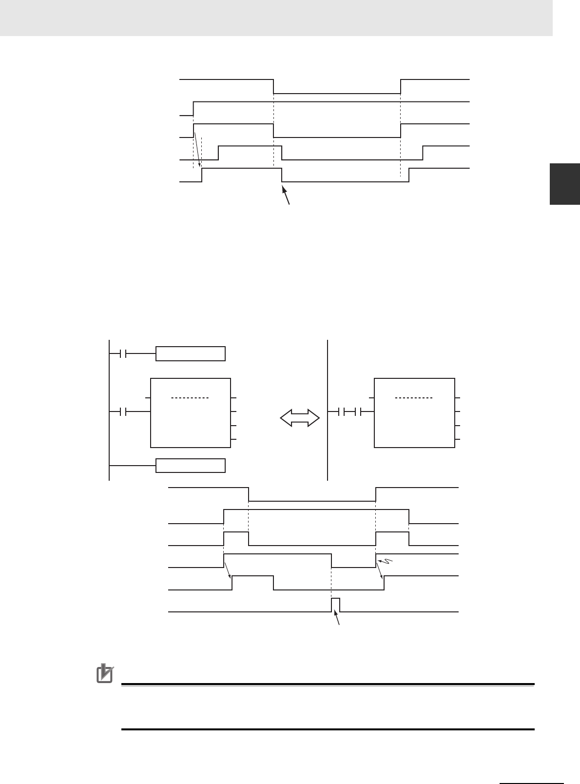
1-11
1 Introduction to Motion Control Instructions
NJ/NX-series Motion Control Instructions Reference Manual (W508)
1-2 Basic Information on Motion
Control Instructions
1
Motion Control Instruction Locations
Execute-type Motion Control Instructions
• Instructions located in master control regions are equivalent to the programming shown on the
right in the following figure.
• When G0 is TRUE, MC_MoveRelative is executed normally.
• When G0 is FALSE, MC_MoveRelative is executed as if the Execute input variable was FALSE.
• Instructions executed when G0 is TRUE continue operation until completion, even if G0 changes
to FALSE during operation. The values of output parameters are also updated in the normal way.
Precautions for Correct UsePrecautions for Correct Use
Execute-type motion control instructions are executed when G0 changes to TRUE. It is not rec-
ommended to use them in the master control region. If they must be used, be careful of the oper-
ation.
IN
PW1.Status_PW
PW1.Busy_PW
G0
Servo ON/OFF
Enable of the motion control instruction changes to
FALSE and the Servo turns OFF.
MC
G0
IN
Execute Done
Rel1
Active
MC_MoveRelative
Axis Axis
Busy
Done_1
Busy_1
Active_1
ING0
Execute Done
Rel1
Active
MC_MoveRelative
Axis Axis
Busy
Done_1
Busy_1
Active_1
Equivalent
MCR
IN
Rel1.Active_1
Rel1.Done_1
Rel1.Busy_1
G0
Rel1.Execute
Positioning starts when
Execute changes to TRUE.
Positioning is completed when Execute changes
to FALSE, so Rel.Done_1 changes to TRUE for
one period.

1 Introduction to Motion Control Instructions
1-12
NJ/NX-series Motion Control Instructions Reference Manual (W508)
Additional Information
• The function of the MC (Master Control Start) instruction is disabled in ST. All instructions in
ST are executed normally.
For details on the MC and MCR instructions, refer to the NJ/NX-series Instructions Reference
Manual (Cat. No. W502).
This section describes the operation of motion control instructions when they are located in ST struc-
tures, such as IF, CASE, WHILE, or REPEAT structures.
When the evaluation result for the condition expression of an ST structure instruction is FALSE, the
motion control instructions within the structure are not executed. Also, the values of the output variables
are not updated.
If execution of an execute-type instruction is started and then the evaluation result changes to FALSE,
processing is continued until it is completed. In that case, however, the values of the output variables
are not updated.
Precautions for Correct UsePrecautions for Correct Use
The execution status of an execute-type instruction in an ST structure will not be clear if the eval-
uation result of the condition expression changes to FALSE during execution of the instruction.
We therefore do not recommend using execution-type instructions in ST structures.
If they must be used, be careful of the operation.
Additional Information
To switch the execution of an execute-type instruction with the condition expression, place only
the Execute input parameter in the ST structure. Place the execute-type instruction itself outside
of the ST structure.
For details on the ST structure instructions, refer to the NJ/NX-series Instructions Reference
Manual (Cat. No. W502).
REAL and LREAL are floating-point decimal data types. This section describes how they are expressed
and processed.
REAL and LREAL Data Sizes
The data sizes of REAL data and LREAL data are different. REAL data has 32 bits and LREAL data
has 64 bits.
Floating-point Decimal Data Format
A real number in floating-point decimal format is expressed using a sign, exponent, and mantissa.
When a real number is substituted in the following formulas, the value corresponding to ‘s’ becomes
the sign, ‘e’ the exponent, and ‘f’ the mantissa.
• REAL Data
Number = (−1)
s
2
e−127
(1 + f × 2
−23
)
• LREAL Data
Number = (−1)
s
2
e−1023
(1 + f × 2
−52
)
Motion Control Instructions in ST Structure Instructions
Treatment of REAL and LREAL Data

1-13
1 Introduction to Motion Control Instructions
NJ/NX-series Motion Control Instructions Reference Manual (W508)
1-2 Basic Information on Motion
Control Instructions
1
Motion Control Instruction Locations
The floating-point data format conforms to the IEEE754 standards. The following formats are used.
Example: Expressing −86.625 as REAL Data
1
Setting the Sign
The number is negative, so s = 1.
2
Binary Expression
The number 86.625 is 1010110.101 as a binary number.
3
Normalized Binary Expression
When the above number is normalized, it becomes 1.010110101 × 2
6
.
4
Exponent Expression
From the previous equation, e-127 = 6. Therefore e = 133. The number 133 is 10000101 as a
binary number. This expresses the exponent.
5
Mantissa Expression
Numbers following the decimal point in 1.010110101 are 010110101. This number is expressed
using 23 bits, but here there are insufficient digits. Therefore zeros are added. The 23-bit figure
becomes f. Therefore f = 01011010100000000000000.
Therefore, −86.625 is expressed as shown in the following figure.
Valid Ranges
The valid ranges of REAL and LREAL are shown in the following table.
Data type
−∞
Negative numbers 0 Positive number
+∞
REAL
−∞
−3.402823e+38 to
−1.175495e-38
0 +1.175495e-38 to
+3.402823e+38
+∞
LREAL
−∞
−1.79769313486231e+308 to
−2.22507385850721e−308
0 +2.22507385850721e−308 to
+1.79769313486231e+308
+∞
se f
31 30 23 22
s
63 62 52 51 0
ef
MantissaExponentSign
LREAL data (64 bits)
MantissaExponentSign
REAL data (32 bits)
0
MantissaExponentSign
REAL data (32 bits)
1 10000101
31 30 23 22
01011010100000000000000
0

1 Introduction to Motion Control Instructions
1-14
NJ/NX-series Motion Control Instructions Reference Manual (W508)
Special Numbers
Positive infinity, negative infinity, +0, −0, and nonnumeric data are called special numbers. Nonnu-
meric data is data that cannot be expressed in floating-point decimal format. They are not treated as
numbers. Mathematically, +0 and −0 both mean the same as 0, but in data processing it is treated
differently.
A detailed explanation is given later. The sign ‘s’, exponent ‘e’, and mantissa ‘f’ for special numbers
take on the following values.
Data type Special number Sign s Exponent e Mantissa f
REAL
+∞
02550
−∞
12550
+0 000
−0
100
Nonnumeric data --- 255 Not 0
LREAL
+∞
0 2047 0
−∞
1 2047 0
+0 000
−0
100
Nonnumeric data --- 2047 Not 0
0
−∞
+∞
REAL −3.402823e+38
LREAL −1.79769313486231e+308
REAL −1.175495e−38
LREAL −2.22507385850721e−308
REAL +1.175495e−38
LREAL +2.22507385850721e−308
REAL +3.402823e+38
LREAL +1.79769313486231e+308

1-15
1 Introduction to Motion Control Instructions
NJ/NX-series Motion Control Instructions Reference Manual (W508)
1-2 Basic Information on Motion
Control Instructions
1
Motion Control Instruction Locations
Subnormal Numbers
Numbers that are very close to 0 (with very small absolute values) cannot be expressed using the
floating-point decimal format. Subnormal numbers were introduced to expand the validity of num-
bers near 0. Subnormal numbers can be used to express numbers whose absolute values are
smaller than numbers expressed in the normal data format.
Additional Information
Values expressed in the normal data format are called normalized numbers or normal numbers.
Numbers with exponent e=0 and mantissa f ≠ 0 are considered subnormal numbers and their values
are expressed in the following manner.
• REAL Data
Number = (−1)
s
2
−126
(f × 2
−23
)
• LREAL Data
Number = (−1)
s
2
−1022
(f × 2
−52
)
Example: Expressing 0.75 x 2
−127
as REAL Data
1
Setting the Sign
The number is positive, so s = 0.
2
Binary Expression
The number 0.75 is 0.11 as a binary number.
3
Mantissa Calculation
From (0.11)
2
× 2
−127
= 2
−126
(f × 2
−23
), f = (0.11)
2
× 2
22
.
4
Mantissa Expression
From the previous equation, f = 01100000000000000000000.
Therefore, 0.75 × 2
−127
is expressed as shown in the following figure.
Subnormal numbers have fewer effective digits than normalized numbers. Therefore, if the calculation
of a normalized number results in an subnormal number, or if an intermediate result is an subnormal
number, the number of effective digits of the calculated result may be less than that of the normalized
number.
0 00000000
31 30 23 22 0
01100000000000000000000
MantissaExponentSign
REAL data (32 bits)

1 Introduction to Motion Control Instructions
1-16
NJ/NX-series Motion Control Instructions Reference Manual (W508)
Data Processing
The floating-point decimal format is an approximate expression of a value, with a slight error from
the actual value. There is a limit to the valid range of the value. For these reasons, the following pro-
cess should be used for calculation.
Rounding
If the actual value exceeds the effective digits of the mantissa, the value must be rounded according
to the following rules.
• Of the values that can be expressed in floating-point decimal format, the value that is closest to
the actual value is taken as the calculation result.
• If there are two values that are equally close to the actual value that can be expressed in floating-
point decimal format, the value with the lowest significant 0 bit is taken as the calculation result.
When there are two values that are equally close to the actual value, the actual value is exactly in
the middle of the two values.
Overflows and Underflows
When the true absolute value exceeds the values that can be expressed by a floating-point data
type, it is called an overflow. On the other hand, if the value is smaller than the values that can be
expressed by a floating-point decimal data type, it is called an underflow.
• If the sign of the true value is positive, the processing result will be positive infinity when an over-
flow occurs. If the sign of the true value is negative, the processing result will be negative infinity
when an overflow occurs.
• If the sign of the true value is positive, the processing result will be +0 when an underflow occurs.
If the sign of the true value is negative, the processing result will be −0 when an overflow occurs.
Calculating with Special Numbers
The following rules apply when calculating with special numbers. For details on special values, refer
to Special Numbers on page 1-14.
• Adding positive infinity and negative infinity results in nonnumeric data.
• Subtracting infinity from infinity with the same signs results in nonnumeric data.
• Multiplying +0 by infinity or −0 by infinity results in nonnumeric data.
• Dividing +0 by +0, −0 by −0, or infinity by infinity results in nonnumeric data.
• Adding +0 and −0 results in +0.
• Subtracting +0 from +0, or −0 from −0 results in +0.
• Basic arithmetic operations including nonnumeric data results in nonnumeric data.
• Comparison instructions such as the CMP instruction treat +0 and −0 as the same value.
• If a nonnumeric number is included in a comparison, the comparison instruction always returns
"not equal."
Precautions for Correct UsePrecautions for Correct Use
Floating-point decimal (LREAL) variables are used to set electronic gears, target positions, and
other parameters of motion control instructions in the MC Function Module. For this reason, cal-
culation results contain rounding errors. For example, if the MC_MoveRelative (Relative Position-
ing) instruction is repeatedly executed, following error will accumulate. If the accumulated error
becomes a problem, set the command unit to pulses, or specify an absolute position with the
MC_MoveAbsolute (Absolute Positioning) instruction.

1-17
1 Introduction to Motion Control Instructions
NJ/NX-series Motion Control Instructions Reference Manual (W508)
1-2 Basic Information on Motion
Control Instructions
1
Multi-execution of Motion Control Instructions
This section describes executing multiple motion control instructions for the same axis within the same
task period.
• In the following programming, instruction instances Move1 and Move2 start in the same task period
when bit a turns ON.
• Instructions in a program are executed from the top. Therefore Move1 is started first, and then Move2
is started before Move1 is finished.
• This is considered multi-execution of motion control instructions (BufferMode). In this example,
Blending is used to execute Move2 in relation to Move1.
For details on multi-execution of motion control instructions, refer to the NJ/NX-series CPU Unit Motion
Control User’s Manual (Cat. No. W507).
Additional Information
If the MC_SetOverride (Set Override Factors) instruction is executed simultaneously in the same
way as the instructions shown above, the override value is valid even when it is placed on the
bottom. When different override values are set with the MC_SetOverride (Set Override Factors)
instruction, the following type of programming is recommended.
Multi-execution of Motion Control Instructions
Move1
Axis
Aborting
Move2
Axis
Blending
Axis 1
Axis 1
Bit a
MC_SetOverride
Axis
rate
MOVE
70
MOVE
50
A
B
C
rate
rate
Axis 1

1 Introduction to Motion Control Instructions
1-18
NJ/NX-series Motion Control Instructions Reference Manual (W508)
You can perform the following online editing operations for motion control instructions from the Sysmac
Studio.
Precautions for Correct UsePrecautions for Correct Use
If instructions to stop the axis motion, such as MC_Stop or MC_GroupStop, are deleted while the
axis is still moving, the axis may not stop depending on the contents of the user program. Make
sure that it is safe to use the online editing before using it for motion control instructions.
An NJ/NX-series CPU Unit has two operating modes: PROGRAM mode and RUN mode. This section
describes the operation of the MC Function Module when the operating mode changes.
• The motion control instruction that is under execution will be aborted. The CommandAborted output
variable remains FALSE, but the operation is the same as when CommandAborted is TRUE.
• If the axis is moving, it will decelerate to a stop at the maximum deceleration. The Servo ON/OFF sta-
tus will continue.
• If saving the cam table is in progress for the Save Cam Table instruction, the save operation contin-
ues.
• If creation of the cam table is in progress for the Generate Cam Table instruction, the creation opera-
tion continues.
• Motion control instructions located in a priority 16 periodic task perform the above process after the
END instruction in the task is executed.
• The output variables of the motion control instructions are cleared.
• The axis decelerates to a stop when the mode changes from RUN mode to PROGRAM mode. If the
operating mode is changed back to RUN mode while the axis is decelerating, the output variables
from the motion control instruction are cleared. Therefore, CommandAborted of the motion control
instruction that was under execution remains FALSE.
Additional Information
• To enable accessing output variables for motion control instructions even after the operating
mode changes, assign variables that have output parameters with a Retain attribute. By
accessing the assigned output parameter, you can access the output variable immediately
before the operating mode changes.
• The Servo ON/OFF status will continue even if the operating mode is changed.
Online Editing of Motion Control Instructions
Online editing operations
Deleting motion control instructions
Adding motion control instructions
Adding input variables, output variables, and in-out variables to motion control instructions
Changing input variables, output variables, and in-out variables in motion control instructions
Deleting input variables, output variables, and in-out variables in motion control instructions.
Changes in the Operating Mode of the CPU Unit
Changes from RUN Mode to PROGRAM Mode
Changes from PROGRAM Mode to RUN Mode

2-1
NJ/NX-series Motion Control Instructions Reference Manual (W508)
2
This section describes the variables and instructions for the Motion Control Function
Module.
2-1 Variables . . . . . . . . . . . . . . . . . . . . . . . . . . . . . . . . . . . . . . . . . . . . . . . . . . . . . 2-2
2-2 Instructions . . . . . . . . . . . . . . . . . . . . . . . . . . . . . . . . . . . . . . . . . . . . . . . . . . 2-31
2-3 PDO Mapping . . . . . . . . . . . . . . . . . . . . . . . . . . . . . . . . . . . . . . . . . . . . . . . . 2-35
Variables and Instructions

2 Variables and Instructions
2-2
NJ/NX-series Motion Control Instructions Reference Manual (W508)
2-1 Variables
There are two types of variables for the MC Function Module.
The first type is system-defined variables, which you use to monitor axis status and some of the param-
eter settings. System-defined variables that are used by the MC Function Module are called system-
defined variables for motion control.
The second type is variables that are used to input arguments to motion control instructions and to out-
put execution status from motion control instructions. Some input variables to motion control instruction
are enumerated variables. With enumerated variables, selections are made from a set of enumerators.
This section describes the variable types, the valid ranges of motion control instruction input variables,
and the enumerated variables.
System-defined Variables for Motion Control
For details on system-defined variables for motion control, refer to the NJ/NX-series CPU Unit
Motion Control User's Manual (Cat. No. W507).
Additional Information
Axis Variables and Axes Group Variables are system-defined variables.
When you use them in the user program, use the system-defined variable names (_MC_AX[*],
_MC1_AX[*], _MC2_AX[*], _MC_GRP[*], _MC1_GRP[*], and _MC2_GRP[*]). You can also use
the variable names that are set on the Sysmac Studio in the user program. You can change the
names of any of the Axis Variables or Axes Group Variables that you create on the Sysmac Stu-
dio. In the following example, the Axis Variable name for the axis that was added for the system-
defined Axis Variable name of _MC_AX[0] has been changed to MyAxis1 in the Sysmac Studio.
Level 1 Level 2 Level 3 Description
System-defined
variables
System-defined
variables for
motion control
MC Common Variable You can monitor the overall status of the MC
Function Module.
Axis Variables You can monitor axis status and the settings of
part of the axis parameters.
Axes Group Variable You can monitor axes group status and the
settings of part of the axes group parameters.
Enable Status
ErrorID
MC_Power_instance
Error
MC_Power
Axis Axis
Busy
MyAxis1
MyAxis1OnStatus
MyAxis1OnBusy
MyAxis1OnError
MyAxis1OnErrorID
MyAxis1
ServoOn
Axis in-out variable
Specify the name
of an Axis Variable.

2-3
2 Variables and Instructions
NJ/NX-series Motion Control Instructions Reference Manual (W508)
2-1 Variables
2
MC Common Variables
Variables for Motion Control Instructions
Additional Information
• Data types that start with “_e” are enumerations.
• Data types that start with “_s” are structures.
For details on the data types that are handled by the MC Function Module, refer to the NJ/NX-
series CPU Unit Motion Control User's Manual (Cat. No. W507).
The variable name _MC_COM is used for the MC Common Variables. The data type is _sCOM-
MON_REF, which is a structure. This section describes the configuration of the MC Common Variables
and provides details on the members.
*1 A CPU Unit with unit version 1.08 or later and Sysmac Studio version 1.09 or higher are required.
Type Outline
Input variables Instruction arguments
Output variables Instruction execution status moni-
toring information
In-out variables Specify data to process with the
instruction
MC Common Variables
Name Data type Meaning Function
_MC_COM _sCOMMON_REF MC Common Variable
Status _sCOMMON_REF_STA MC Common Status
RunMode BOOL MC Run TRUE during MC Function Module opera-
tion.
TestMode BOOL MC Test Run TRUE during test mode operation from the
Sysmac Studio.
CamTableBusy BOOL Cam Table File Save
Busy
TRUE while the Cam Table is being saved
or on standby.
GenerateCamBusy
*1
BOOL Cam Table Creation Busy TRUE while the cam table is being cre-
ated.
PFaultLvl _sMC_REF_EVENT MC Common Partial Fault
Active BOOL MC Common Partial Fault
Occurrence
TRUE while there is an MC common partial
fault.
Code WORD MC Common Partial Fault
Code
Contains the code for an MC common par-
tial fault. The upper four digits of the event
code have the same value.
MFaultLvl _sMC_REF_EVENT MC Common Minor Fault
Active BOOL MC Common Minor Fault
Occurrence
TRUE while there is an MC common minor
fault.
Code WORD MC Common Minor Fault
Code
Contains the code for an MC common
minor fault. The upper four digits of the
event code have the same value.
Obsr _sMC_REF_EVENT MC Common Observation
Active BOOL MC Common Observation
Occurrence
TRUE while there is an MC common
observation.
Code WORD MC Common Observation
Code
Contains the code for an MC common
observation. The upper four digits of the
event code have the same value.

2 Variables and Instructions
2-4
NJ/NX-series Motion Control Instructions Reference Manual (W508)
The variable names of the system-defined Axis Variables are _MC_AX[0..255], _MC1_AX[0..255], and
_MC2_AX[0..255]. This section describes the configuration of the Axis Variables and provides details
on the members using _MC_AX[0..255] as an example. The same information applies to
_MC1_AX[0..255] and _MC2_AX[0..255].
Axis Variables
Name Data type Meaning Function
_MC_AX[0..255] _sAXIS_REF Axis Variable
Status _sAXIS_REF_STA Axis Status
Ready BOOL Axis Ready-to-execute TRUE when preparations for axis execution are
finished and the axis is stopped. This variable
gives the same status as _MC_AX[*].Sta-
tus.Standstill (TRUE: standstill).
Disabled BOOL Axis Disabled TRUE while the Servo is OFF for the axis. This
includes the following status.
The following axis status are mutually exclusive.
Only one of them can be TRUE at a time.
Disabled, Standstill, Discrete, Continuous, Syn-
chronized, Homing, Stopping, ErrorStop, or
Coordinated
Standstill BOOL Standstill TRUE while the Servo is ON for the axis.
Discrete BOOL Discrete Motion TRUE while position control is executed toward
the target position.
This includes when the velocity is 0 because the
override factor was set to 0 during a discrete
motion.
Continuous BOOL Continuous Motion TRUE during continuous motion without a target
position.
This state exists during velocity control and
torque control.
This includes when the velocity is 0 because the
target velocity is set to 0 and when the velocity is
0 due to an override factor set to 0 during contin-
uous motion.
Synchronized BOOL Synchronized Motion TRUE during execution of synchronized control.
This includes waiting for synchronization after
changing to synchronized control instructions.
Homing BOOL Homing TRUE when homing for the MC_Home or
MC_HomeWithParameter instruction.
Stopping BOOL Deceleration Stopping TRUE until the axis stops for a MC_Stop or
MC_TouchProbe instruction. This includes when
Execute is TRUE after the axis stops for an
MC_Stop instruction. Axis motion instructions
are not executed while decelerating to a stop.
(CommandAborted is TRUE.)
ErrorStop BOOL Error Deceleration Stopping This status exists when the axis is stopping or
stopped for execution of the MC_ImdediateStop
instruction or a minor fault (while
_MC_AX[*].MFaultLvl.Active is TRUE (Axis
Minor Fault Occurrence).
Axis motion instructions are not executed in this
state (CommandAborted is TRUE).
Coordinated BOOL Coordinated Motion TRUE when an axes group is enabled by a
multi-axes coordinated control instruction.

2-5
2 Variables and Instructions
NJ/NX-series Motion Control Instructions Reference Manual (W508)
2-1 Variables
2
Axis Variables
Details _sAXIS_REF_DET
Axis Control Status
*1
Idle BOOL Idle TRUE when processing is not currently per-
formed for the command value, except when
waiting for in-position state.
*2
Idle and InPosWaiting are mutually exclusive.
They cannot both be TRUE at the same time.
InPosWaiting BOOL In-position Waiting TRUE when waiting for in-position state. The in-
position check is performed when positioning for
the in-position check.
Homed BOOL Home Defined
TRUE when home is defined.
*3
TRUE: Home defined.
FALSE: Home not defined.
InHome BOOL In Home Position TRUE when the axis is in the range for home. It
gives an AND of the following conditions.
• Home defined
• The actual current position is in the zero posi-
tion range with home as the center.
TRUE also when the zero position is passed by
while the axis is moving in command status.
VelLimit
*4
BOOL Command Velocity Satura-
tion
TRUE while the axis velocity is held to the maxi-
mum velocity during synchronized control.
Dir _sAXIS_REF_DIR
Command Direction
*5
Posi BOOL Positive Direction TRUE when there is a command in the positive
direction.
Nega BOOL Negative Direction TRUE when there is a command in the negative
direction.
DrvStatus _sAX-
IS_REF_STA_DRV
Servo Drive Status
*6
ServoOn BOOL Servo ON TRUE when the Servomotor is powered.
Ready BOOL Servo Ready TRUE when the Servo is ready.
MainPower BOOL Main Power TRUE when the Servo Drive main power is ON.
P_OT BOOL Positive Limit Input TRUE when the positive limit input is enabled.
N_OT BOOL Negative Limit Input TRUE when the negative limit input is enabled.
HomeSw BOOL Home Proximity Input TRUE when the home proximity input is
enabled.
Home BOOL Home Input
TRUE when the home input is enabled.
*7
ImdStop BOOL Immediate Stop Input TRUE when the immediate stop input is
enabled.
Latch1 BOOL External Latch Input 1 TRUE when latch input 1 is enabled.
Latch2 BOOL External Latch Input 2 TRUE when latch input 2 is enabled.
DrvAlarm BOOL Drive Error Input TRUE while there is a Servo Drive error.
DrvWarning BOOL Drive Warning Input TRUE while there is a Servo Drive warning.
ILA BOOL Drive Internal Limiting TRUE when the Servo Drive limiting function
actually limits the axis.
*8
CSP BOOL Cyclic Synchronous Posi-
tion (CSP) Control Mode
TRUE when the Servo is ON at the Servo Drive
and the current mode is CSP Mode.
*9
CSV BOOL Cyclic Synchronous Velocity
(CSV) Control Mode
TRUE when the Servo is ON at the Servo Drive
and the current mode is CSV Mode.
*9
CST BOOL Cyclic Synchronous Torque
(CST) Control Mode
TRUE when the Servo is ON at the Servo Drive
and the current mode is CST Mode.
*9
Name Data type Meaning Function

2 Variables and Instructions
2-6
NJ/NX-series Motion Control Instructions Reference Manual (W508)
Cmd _sAXIS_REF_CMD_
DATA
Axis Command Value
Pos LREAL Command Current Position Contains the current value of the command posi-
tion. (Unit: command units)
When the Servo is OFF and the mode is not
position control mode, this variable contains the
actual current position.
*10
Vel LREAL Command Current Velocity Contains the current value of the command
velocity. (Unit: command units/s)
A plus sign is added when traveling in the posi-
tive direction, and a minus sign when traveling in
the negative direction. The velocity is calculated
from the difference with the command current
position. When the Servo is OFF and the mode
is not the position control mode, the velocity is
calculated based on the actual current position.
AccDec LREAL Command Current Acceler-
ation/Deceleration
Contains the current value of the command
acceleration/deceleration rate. (Unit: command
units/s
2
)
The acceleration/deceleration rate is calculated
from the difference with the command current
velocity. A plus sign is added for acceleration,
and a minus sign is added for deceleration. Zero
when the command acceleration/deceleration
rate of the instruction under execution is 0.
Jerk LREAL Command Current Jerk Contains the current value of the command jerk.
(Unit: command units/s
3
)
A plus sign is added when the absolute value of
acceleration/deceleration is increasing, and a
minus sign is added when it is decreasing. Zero
when the command acceleration/deceleration
rate and command jerk of the instruction under
execution is 0.
Trq LREAL Command Current Torque Contains the current value of the command
torque. (Unit: %)
A plus sign is added when traveling in the posi-
tive direction, and a minus sign when traveling in
the negative direction. Contains the same value
as the actual current torque except in torque
control mode.
Act _sAXIS_REF_ACT_-
DATA
Axis Current Value
Pos LREAL Actual Current Position Contains the actual current position. (Unit: com-
mand units)
*10
Vel LREAL Actual Current Velocity Contains the actual current velocity. (Unit: com-
mand units/s)
A plus sign is added when traveling in the posi-
tive direction, and a minus sign when traveling in
the negative direction.
Trq LREAL Actual Current Torque Contains the current value of the actual torque.
(Unit: %)
A plus sign is added when traveling in the posi-
tive direction, and a minus sign when traveling in
the negative direction.
TimeStamp
*11
ULINT Time Stamp Contains the time when the current position of
the axis was updated. This variable is valid for
an axis for which time stamping is operating.
(Unit: ns)
MFaultLvl _sMC_REF_EVENT Axis Minor Fault
Active BOOL Axis Minor Fault Occur-
rence
TRUE while there is an axis minor fault.
Code WORD Axis Minor Fault Code Contains the code for an axis minor fault. The
upper four digits of the event code have the
same value.
Name Data type Meaning Function

2-7
2 Variables and Instructions
NJ/NX-series Motion Control Instructions Reference Manual (W508)
2-1 Variables
2
Axis Variables
*1 Gives the control status of the command.
*2 This also includes states where processing is performed while in motion at velocity 0, during following error counter
resets, during synchronized control, and during multi-axes coordinated control motion.
*3 Even if the variable is TRUE, the home must be defined again in the following cases.
When you make a change in the position count settings or the unit conversion settings.
If an error or erroneous operation occurs on the Servo Drive, which leads to loss of absolute position data. Examples of
errors and erroneous operations include breaks of encoder cables and clear of absolute encoder data.
Obsr _sMC_REF_EVENT Axis Observation
Active BOOL Axis Observation Occur-
rence
TRUE while there is an axis observation.
Code WORD Axis Observation Code Contains the code for an axis observation. The
upper four digits of the event code have the
same value.
Cfg _sAXIS_REF_CFG
Axis Basic Settings
*12
AxNo UINT Axis Number Contains the logical number of the axis.
This number is accessed to recognize the axis
number when accessing _sAXIS_REF.
AxEnable _eMC_AXIS_USE Axis Use Shows if the axis is enabled or disabled.
0: _mcNoneAxis (Undefined Axis)
1: _mcUnusedAxis (Unused Axis)
2: _mcUsedAxis (Used Axis)
AxType _eMC_AXIS_TYPE Axis Type Contains the axis type.
I/O wiring is not required for virtual axes.
0: _mcServo (Servo Axis)
1: _mcEncdr (Encoder Axis)
2: _mcVirServo (Virtual Servo Axis)
3: _mcVirEncdr (Virtual Encoder Axis)
NodeAddress UINT Node Address
Contains the EtherCAT slave address.
*13
A value of 16#FFFF indicates that there is no
address.
ExecID
*14
UNIT Execution ID Contains the task execution ID.
0: Not assigned to task (undefined axis).
1: Assigned to primary periodic task
2: Assigned to priority-5 periodic task
Scale _sAXIS_REF_SCALE
Unit Conversion Settings
*15
Num UDINT Command Pulse Count Per
Motor Rotation
Contains the number of pulses per motor rota-
tion for command positions.
The command value is converted to a number of
pulses based on the electronic gear ratio.
Den LREAL Work Travel Distance Per
Motor Rotation
Contains the workpiece travel distance per
motor rotation for command positions.
*16
Units _eMC_UNITS Unit of Display Contains the display unit for command positions.
0: _mcPls(pulse)
1: _mcMm(mm)
2: _mcUm(μm)
3: _mcNm(nm)
4: _mcDeg(degree)
5: _mcInch(inch)
CountMode
*14
_eMC_COUNT_MODE Count Mode Contains the count mode.
0: _mcCountModeLinear (Linear Mode)
1: _mcCountModeRotary (Rotary Mode)
MaxPos
*14
LREAL Maximum current position Contains the maximum value of the current posi-
tion indication.
*17
MinPos
*14
LREAL Minimum current position Contains the minimum value of the current posi-
tion indication.
*18
Name Data type Meaning Function

2 Variables and Instructions
2-8
NJ/NX-series Motion Control Instructions Reference Manual (W508)
*4 Use VelLimit only for a slave axis that is currently in synchronized control.
*5 Gives the command travel direction.
*6 Gives the status of the Servo Drive or other device.
*7 This variable shows the status of the signal that is set for the Encoder Phase Z Detection setting of the digital inputs in the
Detailed Settings Area of the Axis Basic Settings Display of the Sysmac Studio. You may not be able to map this signal to
a PDO for a servo driver from another manufacturer. Refer to the manual for the servo driver.
*8 This variable shows the status of bit 11(internal limit active) of the Status word (6041 hex) mapped to a PDO. The condi-
tion for it to change to TRUE depends on the specifications of the Servo Drive. Refer to the manual for the servo driver.
This corresponds to one of the following limits in the OMRON 1S-series Servo Drive or G5-series Servo Drive.
Torque limit
Velocity limit
Drive prohibit input
Software limits
*9 These variables are based on the value of the Modes of operation display (6061 hex) mapped to a PDO. The conditions
for CSP, CSV, and CST to change to TRUE depend on the specifications of the Servo Drive. Refer to the manual for the
servo driver. If the Modes of Operation Display (6061 hex) is not mapped to a PDO, the values of these variables depend
on the unit version of the CPU Unit as follows:
For a CPU Unit with unit version 1.09 or earlier, they are always FALSE.
For a CPU Unit with unit version 1.10 or later, they are TRUE when the status of the Statusword (6041 hex) that was
mapped to a PDO is Operation Enabled.
*10 Operation when process data communications is not established between the CPU Unit and an EtherCAT slave assigned
to an axis or between the CPU Unit and an NX Unit depends on the version of the CPU Unit as follows:
For CPU Unit version 1.09 or earlier, the actual current position and command current position in the Axis Variable will be
either 0 or the lower limit value. The lower limit value is used when the Count Mode is set to Rotary Mode and 0 is not
included in the positioning range.
For CPU Unit version 1.10 or later, the actual current position and command current position in the Axis Variable will be
the actual current position from just before process data communications changed to a non-established state.
*11 A CPU Unit with unit version 1.06 or later and Sysmac Studio version 1.07 or higher are required to use this variable.
*12 This variable shows the settings in the Axis Basic Settings.
*13 For an NX-series Position Interface Unit, this is the node address of the EtherCAT Coupler Unit under which the Position
Interface Unit is mounted.
*14 A CPU Unit with unit version 1.10 or later and Sysmac Studio version 1.12 or higher are required to use this variable.
*15 This variable shows the settings of the electronic gear ratio.
*16 The parameter is disabled if you set to use a reducer in the unit conversion settings, which is the function added for CPU
Units with unit version 1.11 or later. To confirm alternatively enabled parameters, i.e. Work Travel Distance Per Rotation,
Work Gear Ratio, and Motor Gear Ratio, use the MC_ReadAxisParameter (Read Axis Parameters) instruction.
*17 If the Count Mode is set to Linear Mode, the position just before an overflow is given. In Rotary Mode, the modulo maxi-
mum position is given.
*18 If the Count Mode is set to Linear Mode, the position just before an underflow is given. In Rotary Mode, the modulo mini-
mum position is given.

2-9
2 Variables and Instructions
NJ/NX-series Motion Control Instructions Reference Manual (W508)
2-1 Variables
2
Axes Group Variables
The variable names of the system-defined Axes Group Variables are _MC_GRP[0..63],
_MC1_GRP[0..63], and _MC2_GRP[0..63]. The data type is _sGROUP_REF, which is a structure. This
section describes the configuration of the Axes Group Variables and provides details on the members
using _MC_GRP[0..63] as an example. The same information applies to _MC1_GRP[0..63] and
_MC2_GRP[0..63]. In the descriptions of functions, _MC_AX[*] is used as an example, but the same
information applies to _MC1_AX[*] and _MC2_AX[*].
Axes Group Variables
Name Data type Meaning Function
_MC_GRP[0..63] _sGROUP_REF Axes Group Variable
Status _sGROUP_REF_STA Axes Group Status
Ready BOOL Ready-to-execute TRUE when the axes group is stopped and is
ready to execute. The condition for being
ready to execute is an AND of the following
conditions.
• Execution of the MC_Stop instruction is not
in progress for a composition axis.
• _MC_GRP[*].Status.Standby (standby) is
TRUE.
• The Servo is ON for the composition axes.
• _MC_AX[*].Details.Homed is TRUE (home
defined) for the composition axes.
Disabled BOOL Axes Group Disabled TRUE when the axes group is disabled and
stopped. The following axes group status are
mutually exclusive. Only one of them can be
TRUE at a time.
Disabled, Standby, Moving, Stopping, or Error-
Stop
Standby BOOL Standby TRUE when the axes group motion instruction
is stopped.
This is not related to the Servo ON/OFF status
of the composition axes in the axes group.
Moving BOOL Moving TRUE while an axes group motion instruction
is executed toward the target position.
This includes in-position waiting status and
when the velocity is 0 for an override.
Stopping BOOL Deceleration Stopping TRUE until the axes group stops for an
MC_GroupStop instruction. This includes when
Execute is TRUE after the axis stops for an
MC_GroupStop instruction. Axes group motion
instructions are not executed while decelerat-
ing to a stop. (CommandAborted is TRUE.)
ErrorStop BOOL Error Deceleration Stop-
ping
TRUE while the axes group is stopping or
stopped for the MC_GroupImmediateStop
instruction or during an axes group minor fault
(when _MC_GRP[*].MFaultLvl.Active is
TRUE). Axes group motion instructions are not
executed in this state (CommandAborted is
TRUE).
Details _sGROUP_REF_DET
Axes Group Control Status
*1
Idle BOOL Idle TRUE when processing is not currently per-
formed for the command value, except when
waiting for in-position state.
*2
Idle and InPosWaiting are mutually exclusive.
They cannot both be TRUE at the same time.
InPosWaiting BOOL In-position Waiting TRUE when any of the composition axes are
waiting for in-position state. The in-position
check performed when positioning for the in-
position check.

2 Variables and Instructions
2-10
NJ/NX-series Motion Control Instructions Reference Manual (W508)
Cmd _sGROUP_REF_CMD_-
DATA
Axes Group Command Values
Vel LREAL Command Interpolation
Velocity
Contains the current value of the command
interpolation velocity. The interpolation velocity
is calculated from the difference with the inter-
polation command current position. A plus sign
is added when traveling in the positive direc-
tion, and a minus sign is added when traveling
in the negative direction. The value is 0 when
the axes group is disabled.
AccDec LREAL Command Interpolation
Acceleration/Deceleration
Contains the current value of the command
interpolation acceleration/deceleration. The
interpolation acceleration/deceleration rate is
calculated from the difference with the com-
mand interpolation velocity. A plus sign is
added for acceleration, and a minus sign is
added for deceleration. The value is 0 when
the axes group is disabled, or when the com-
mand acceleration/deceleration rate of the cur-
rent axes group motion instruction is 0.
MFaultLvl _sMC_REF_EVENT Axes Group Minor Fault
Active BOOL Axes Group Minor Fault
Occurrence
TRUE while there is an axes group minor fault.
Code UINT Axes Group Minor Fault
Code
Contains the code for an axes group minor
fault. The upper four digits of the event code
have the same value.
Obsr _sMC_REF_EVENT Axes Group Observation
Active BOOL Axes Group Observation
Occurrence
TRUE while there is an axes group observa-
tion.
Code WORD Axes Group Observation
Code
Contains the code for an axes group observa-
tion. The upper four digits of the event code
have the same value.
Cfg _sGROUP_REF_CFG Axes Group Basic Settings
GrpNo UINT Axes Group Number Contains the logical number of the axes group.
This number is accessed to recognize the axes
group number when accessing
_sGROUP_REF.
GrpEnable _eMC_GROUP_USE Axes Group Use Shows if the axes group is enabled or dis-
abled.
0: _mcNoneGroup (Undefined Axes Group)
1: _mcUnusedGroup (Unused Axes Group)
2: _mcUsedGroup (Used Axes Group)
ExecID
*3
UNIT Execution ID Contains the assigned task execution ID.
0: Not assigned to task (undefined axes
group).
1: Assigned to primary periodic task
2: Assigned to priority-5 periodic task
Name Data type Meaning Function

2-11
2 Variables and Instructions
NJ/NX-series Motion Control Instructions Reference Manual (W508)
2-1 Variables
2
Axes Group Variables
*1 Gives the control status of the command.
*2 This also includes states where processing is performed while in motion at a velocity of 0.
*3 A CPU Unit with unit version 1.10 or later and Sysmac Studio version 1.12 or higher are required to use this variable.
*4 Gives the definition of the kinematic conversions for the axes group.
Kinematics _sGROUP_REF_KIM
Kinematics Transformation Settings
*4
GrpType _eMC_GROUP_TYPE Composition Gives the axis composition for multi-axes coor-
dinated control.
0: _mcXY (two axes)
1: _mcXYZ (three axes)
2: _mcXYZU (four axes)
Axis[0] UINT Composition Axis for Axis
A0
Gives the axis number that is assigned to axis
A0.
Axis[1] UINT Composition Axis for Axis
A1
Gives the axis number that is assigned to axis
A1.
Axis[2] UINT Composition Axis for Axis
A2
Gives the axis number that is assigned to axis
A2.
Axis[3] UINT Composition Axis for Axis
A3
Gives the axis number that is assigned to axis
A3.
Name Data type Meaning Function

2 Variables and Instructions
2-12
NJ/NX-series Motion Control Instructions Reference Manual (W508)
The following tables list the input variables and the valid ranges for motion control instructions, and the
valid ranges of enumerations.
Input Variables for Motion Control Instructions
Input Variables
Name Meaning Data type Valid range Default Description
Execute Execute BOOL TRUE or FALSE FALSE The instruction is executed
when Execute changes to
TRUE. Other input vari-
ables are also input when
Execute changes to TRUE.
If input values are changed,
they will be updated when
Execute changes to TRUE
again. The output variables
are valid as long as Execute
remains TRUE even after
the instruction is completed.
Then, all output variables
except for Error and ErrorID
are disabled when Execute
changes to FALSE. If Exe-
cute changes to FALSE
before the instruction is
completed, output vari-
ables are valid for at least
one period.
Enable Enable BOOL TRUE or FALSE FALSE The instruction function is
enabled when Enable
changes to TRUE and dis-
abled when it changes to
FALSE. While Enable is
TRUE, the other input vari-
ables are input every
period. If Enable changes to
FALSE, all output variables
except for Error and ErrorID
are disabled.
PositiveEnable Positive
Direction
Enable
BOOL TRUE or FALSE FALSE • MC_MoveJog Instruction
When this variable
changes to TRUE, the
axis starts moving in the
positive direction. When it
changes to FALSE, the
axis stops moving. The
Velocity, Acceleration,
and Deceleration input
variables to the
MC_MoveJog instruction
are read when Posi-
tiveEnable changes to
TRUE.
• MC_SetTorqueLimit
Instruction
When this variable
changes to TRUE, the
positive torque limit is
enabled. When it changes
to FALSE, the positive
torque limit is disabled.

2-13
2 Variables and Instructions
NJ/NX-series Motion Control Instructions Reference Manual (W508)
2-1 Variables
2
Input Variables for Motion Control Instructions
NegativeEnable Negative
Direction
Enable
BOOL TRUE or FALSE FALSE • MC_MoveJog Instruction
When this variable
changes to TRUE, the
axis starts moving in the
negative direction. When
it changes to FALSE, the
axis stops moving. The
Velocity, Acceleration,
and Deceleration input
variables to the
MC_MoveJog instruction
are read when Nega-
tiveEnable changes to
TRUE.
• MC_SetTorqueLimit
Instruction
When this variable
changes to TRUE, the
negative torque limit is
enabled. When it changes
to FALSE, the negative
torque limit is disabled.
BufferMode Buffer Mode
Selection
_eMC_BUFFER_MODE 0: _mcAborting
1: _mcBuffered
2: _mcBlendingLow
3: _mcBlendingPrevious
4: _mcBlendingNext
5: _mcBlendingHigh
0
*1
Specifies the operation
when executing more than
one motion instruction.
0: Aborting
1: Buffered
2: Blending low
3: Blending previous
4: Blending next
5: Blending high
Velocity Target
Velocity
LREAL
Positive number*2
0 Specifies the target veloc-
ity.
*3
Acceleration Acceleration
Rate
LREAL Non-negative number 0 Specifies the acceleration
rate.
*4
Deceleration Deceleration
Rate
LREAL Non-negative number 0 Specifies the deceleration
rate.
*4
Jerk Jerk LREAL Non-negative number 0
Specifies the jerk.
*5
Distance Travel
Distance
LREAL Negative number, positive number,
or 0
0 Specifies the travel distance
from the command current
position.
ARRAY [0..3] OF LREAL Negative number, positive number,
or 0
0 Specifies the target posi-
tion for linear interpola-
tion.
*6
Position Target
Position
LREAL Negative number, positive number,
or 0
0 Specifies the absolute tar-
get position.
*6
ARRAY [0..3] OF LREAL Negative number, positive number,
or 0
0 Specifies the target posi-
tion for linear interpola-
tion.
*6
VelFactor Velocity
Override
Factor
LREAL 0 to 500 100 Specifies the velocity over-
ride factor.
The valid range of the over-
ride factors is between
0.01and 500.00.
Values above 500.00 are
treated as 500 and values
less then 0.01 (including
negative values) are treated
as 0.01.
The override factor will be 0
only when 0 is specified.
The unit is %.
Name Meaning Data type Valid range Default Description

2 Variables and Instructions
2-14
NJ/NX-series Motion Control Instructions Reference Manual (W508)
AccFactor
(Reserved)
Acceleration/
Deceleration
Override
Factor
LREAL 0 to 500 100 (Reserved)
JerkFactor
(Reserved)
Jerk
Override
Factor
LREAL 0 to 500 100 (Reserved)
ReferenceType
*7
Position
Type Selec-
tion
_eMC_REFERENCE_-
TYPE
0: _mcCommand
1: _mcFeedback
2: _mcLatestCommand
0
*1
Specifies the master axis
input information.
0: Command position
(value calculated in the
previous task period
*8
)
1: Actual position (value
obtained in the same
task period
*8
)
2: Command position
(value calculated in the
same task period
*8
)
FeedDistance Feed Dis-
tance
LREAL Negative number, positive number,
or 0
0 Specifies the travel distance
after the interrupt feed
input.
FeedVelocity Feed Veloc-
ity
LREAL Positive number 0 Specifies the travel target
velocity after the interrupt
feed input.
ErrorDetect Error Detec-
tion Selec-
tion
BOOL TRUE or FALSE FALSE Specifies whether to detect
an error when there is no
interrupt feed input.
TRUE: Detect errors.
FALSE: Do not detect
errors.
Periodic Periodic
Mode
BOOL TRUE or FALSE FALSE Specifies whether to exe-
cute the specified cam table
periodically or only once.
TRUE: Periodic
FALSE: Non-periodic
StartMode Start Mode _eMC_STARTMODE 0: _mcAbsolutePosition
1: _mcRelativePosition
0
*1
Specifies the coordinates
used by MasterStartDis-
tance (master following dis-
tance).
0: Absolute position
1: Relative position
StartPosition Cam Table
Start Position
LREAL Negative number, positive number,
or 0
0 Specifies the starting point
of the cam table (0 phase)
as an absolute position of
the master axis.
MasterStartDis-
tance
Master
Following
Distance
LREAL Negative number, positive number,
or 0
0 Specifies the position of the
master axis when the fol-
lowing axis starts the cam
motion. If you specify abso-
lute positioning for Start-
Mode, specify the absolute
position of the master axis.
If you specify relative posi-
tioning for StartMode, spec-
ify the relative position of
the master axis from Start-
Position (Cam Table Start
Position).
MasterScaling Master
Coefficient
LREAL Positive value (>0.0) 1.0 The master axis phase is
extended or contracted
using the specified scale.
Name Meaning Data type Valid range Default Description

2-15
2 Variables and Instructions
NJ/NX-series Motion Control Instructions Reference Manual (W508)
2-1 Variables
2
Input Variables for Motion Control Instructions
SlaveScaling Slave Axis
Coefficient
LREAL Positive value (>0.0) 1.0 The slave axis displace-
ment is extended or con-
tracted using the specified
scale.
MasterOffset Master
Offset
LREAL Negative number, positive number,
or 0
0 The phase of the master
axis is shifted using the
specified offset value.
SlaveOffset Slave Offset LREAL Negative number, positive number,
or 0
0 The displacement of the
slave axis is shifted using
the specified offset value.
CamTransition
(Reserved)
Cam Transi-
tion Selec-
tion
_eMC_CAM_
TRANSITION
0: _mcCTNone
0
*1
(Reserved)
OutMode
(Reserved)
Sync End
Mode Selec-
tion
_eMC_OUT_MODE 0: _mcStop
0
*1
(Reserved)
Direction Direction _eMC_DIRECTION 0: _mcPositiveDirection
1: _mcShortestWay
2: _mcNegativeDirection
3: _mcCurrentDirection
4: _mcNoDirection
4/0
*1
Specifies the travel direc-
tion.
0: Positive direction
1: Shortest way
2: Negative direction
3: Current direction
4: No direction specified
Continuous(Res
erved)
Continuation
Mode Selec-
tion
BOOL TRUE or FALSE FALSE (Reserved)
RatioNumerator Gear Ratio
Numerator
DINT
*9
Positive or negative number
*9
10,000 Specifies the electronic
gear ratio numerator
between the master and
slave axes.
Ratio
Denominator
Gear Ratio
Denominator
UDINT
*10
Positive number 10,000 Specifies the electronic
gear ratio denominator
between the master and
slave axes.
MasterSync
Position
Master Sync
Position
LREAL Negative number, positive number,
or 0
0 Specifies the absolute mas-
ter sync position.
SlaveSyncPosi-
tion
Slave Sync
Position
LREAL Negative number, positive number,
or 0
0 Specifies the absolute slave
sync position.
SlaveDistance Slave Axis
Travel
Distance
LREAL Negative number, positive number,
or 0
0 Specifies the travel distance
for the slave axis.
MasterDistance Master Axis
Travel
Distance
LREAL Non-negative number 0 Specifies the travel distance
of the master axis.
MasterDistan-
ceInACC
Master
Distance in
Acceleration
LREAL Non-negative number 0 Specifies the travel distance
of the master axis while the
slave axis is accelerating.
MasterDistan-
ceInDEC
Master
Distance in
Deceleration
LREAL Non-negative number 0 Specifies the travel distance
of the master axis while the
slave axis is decelerating.
LinkOption Synchroniza-
tion Start
Condition
_eMC_LINKOPTION 0: _mcCommandExecution
1: _mcTriggerDetection
2: _mcMasterReach
0
*1
Specifies the condition for
the slave axis to synchro-
nize with the master axis.
0: When instruction execu-
tion starts
1: When trigger is detected
2: When the master axis
reaches the master fol-
lowing distance.
Name Meaning Data type Valid range Default Description

2 Variables and Instructions
2-16
NJ/NX-series Motion Control Instructions Reference Manual (W508)
CombineMode Combine
Mode
_eMC_COMBINE_-
MODE
0: _mcAddAxes
1: _mcSubAxes
0
*1
Specifies the combining
method.
0: Addition
1: Subtraction
Ratio
Numerator
Master
(Reserved)
Master Axis
Gear Ratio
Numerator
DINT
*9
Positive or negative number
*9
10000 Specifies the electronic
gear ratio numerator
between the master and
slave axes.
Ratio
Denominator
Master
(Reserved)
Master Axis
Gear Ratio
Denominator
UDINT
*10
Positive number 10000 Specifies the denominator
of the electronic gear ratio
between the master and
slave axes.
Ratio
Numerator
Auxiliary
(Reserved)
Auxiliary Axis
Gear Ratio
Numerator
DINT
*9
Positive or negative number
*9
10000 Specifies the numerator of
the electronic gear ratio
between the auxiliary and
slave axes.
Ratio
Denominator
Auxiliary
(Reserved)
Auxiliary Axis
Gear Ratio
Denominator
UDINT
*10
Positive number 10000 Specifies the denominator
of the electronic gear ratio
between the auxiliary and
slave axes.
ReferenceType
Master
Master Axis
Position
Type
_eMC_
REFERENCE_TYPE
1: _mcFeedback
2: _mcLatestCommand
2
*1
Specifies the position type
of the master axis.
1: Actual position (value
obtained in the same
task period
*8
)
2: Command position
(value calculated in the
same task period
*8
)
ReferenceType
Auxiliary
Auxiliary Axis
Position
Type
_eMC_
REFERENCE_TYPE
1: _mcFeedback
2: _mcLatestCommand
2
*1
Specifies the position type
of the auxiliary axis.
1: Actual position (value
obtained in the same
task period
*8
)
2: Command position
(value calculated in the
same task period
*8
)
PhaseShift Phase Shift
Amount
LREAL Negative number, positive number,
or 0
0 Specifies the master phase
shift amount.
*6
Torq ue Targ et
Torq ue
LREAL 0 to 1000.0 300.0 Specify the target torque to
output to the Servo Drive in
increments of 0.1%. The
target torque is specified as
a percentage of the rated
torque. The unit is %.
TorqueRamp Torque
Ramp
LREAL Non-negative number 0 Specifies the rate of change
in the torque from the cur-
rent value to the target
torque. The unit is %/s.
PositiveValue Positive
Torque Limit
LREAL 0.1 to 1000.0 or 0.0 300.0 Specifies the torque limit in
the positive direction in
increments of 0.1%.
If a value that exceeds the
Maximum Positive Torque
Limit axis parameter, the
positive torque will be the
Maximum Positive Torque
Limit.
The value will be 0 if 0 or a
negative value is specified.
Name Meaning Data type Valid range Default Description

2-17
2 Variables and Instructions
NJ/NX-series Motion Control Instructions Reference Manual (W508)
2-1 Variables
2
Input Variables for Motion Control Instructions
NegativeValue Negative
Torque Limit
LREAL 0.1 to 1000.0 or 0.0 300.0 Specifies the torque limit in
the negative direction in
increments of 0.1%.
If a value that exceeds the
Maximum Negative Torque
Limit axis parameter, the
negative torque will be the
Maximum Negative Torque
Limit.
The value will be 0 if 0 or a
negative value is specified.
WindowOnly Window Only BOOL TRUE or FALSE FALSE Specify whether to enable
or disable the window
mask.
FirstPosition First Position LREAL Negative number, positive number,
or 0
0 Specify the first position.
LastPosition Last Position LREAL Negative number, positive number,
or 0
0 Specify the last position.
StopMode Stopping
Mode
Selection
_eMC_STOP_MODE 1: _mcImmediateStop
2: _mcImmediateStopFEReset
3: _mcFreeRunStop
4: _mcNonStop
4
*1
Specifies the stopping
method.
1: Perform an immediate
stop.
2: Perform an immediate
stop and reset the fol-
lowing error counter
3: Perform an immediate
stop and turn OFF the
Servo
4: Do not stop.
Relative
(Reserved)
Relative
Position
Selection
BOOL TRUE or FALSE FALSE (Reserved)
Execution
Mode (Reserved)
Execution
Mode
_eMC_EXECUTION_-
MODE
0: _mcImmediately
0
*1
(Reserved)
Permitted
Deviation
Permitted
Following
Error
LREAL Non-negative number 0 Specifies the permitted
maximum value for the fol-
lowing error between the
master and slave axes.
CmdPos
Mode
Command
Current
Position
Count
Selection
_eMC_CMDPOS_
MODE
0: _mcCount
0
*1
0: Use the actual current
position and update the
command current posi-
tion.
Home remains defined.
CoordSystem Coordinate
System
_eMC_COORD_SYS-
TEM
0: _mcACS
0
*1
Specifies the coordinate
system.
0: Axis coordinate system
(ACS)
TransitionMode Transition
Mode
_eMC_TRANSITION_-
MODE
0: _mcTMNone
10: _mcTMCornerSuperimposed
0
*1
Specifies the path of
motion.
0: Transition disabled
10:Superimpose corners
MoveMode Travel Mode _eMC_MOVE_MODE 0: _mcAbsolute
1: _mcRelative
0
*1
Selects the travel method.
0: Absolute positioning
1: Relative positioning
CircAxes Circular Axes ARRAY [0,1] OF UINT 0 to 3 0 Specifies the axes for circu-
lar interpolation.
0: Axis A0
1: Axis A1
2: Axis A2
3: Axis A3
Name Meaning Data type Valid range Default Description

2 Variables and Instructions
2-18
NJ/NX-series Motion Control Instructions Reference Manual (W508)
CircMode Circular
Interpolation
Mode
_eMC_CIRC_MODE 0: _mcBorder
1: _mcCenter
2: _mcRadius
0
*1
Specifies the method for cir-
cular interpolation.
0: Border point
1: Center
2: Radius
AuxPoint Auxiliary
Point
ARRAY [0,1] OF LREAL Negative number, positive number,
or 0
0 Specifies the border point,
center, or radius.
EndPoint End Point ARRAY [0,1] OF LREAL Negative number, positive number,
or 0
0 Specifies the target posi-
tion.
PathChoice Path Choice _eMC_CIRC_PATH-
CHOICE
0: _mcCW
1: _mcCCW
0
*1
Specifies the path direction.
0: CW
1: CCW
ParameterNum-
ber
Parameter
Number
_eMC_PARAME-
TER_NUMBER
0: _mcChkVel
1: _mcChkAcc
2: _mcChkDec
3: _mcPosiChkTrq
*11
4: _mcNegaChkTrq
*11
5: _mcFELmt
6: _mcChkFELmt
7: _mcSwLmtMode
8: _mcPosiSwLmt
9: _mcNegaSwLmt
10: _mcInPosTime
11: _mcInPosRange
*12
12: _mcStartVel
*13
0
*1
Specifies the parameter to
write.
0: Velocity Warning
Value/Interpolation
Velocity Warning Value
1: Acceleration Warning
Value/Interpolation
Acceleration Warning
Value
2: Deceleration Warning
Value/Interpolation
Deceleration Warning
Value
3: Positive Torque Warn-
ing Value
4: Negative Torque Warn-
ing Value
5: Following Error Over
Value
6: Following Error Warning
Value
7: Software Limits
8: Positive Software Limit
9: Negative Software Limit
10:In-position Check Time
11:In-position Range
12:Start Velocity
HomingMode
*14
Homing
Method
_eMC_HOMING_MODE 0: _mcHomeSwTurnHomeSwOff
1: _mcHomeSwTurnHomeSwOn
4: _mcHomeSwOff
5: _mcHomeSwOn
8: _mcLimitInputOff
9: _mcHomeSwTurnHomeMask
11: _mcLimitInputOnly
12: _mcHomeSwTurnHoldingTime
13: _mcNoHomeSwHolding
HomeInput
14: _mcHomePreset
0
*1
Specify the new setting of
the Homing Method.
0: Proximity reverse
turn/home proximity
input OFF
1: Proximity reverse
turn/home proximity
input ON
4: Home proximity input
OFF
5: Home proximity input
ON
8: Limit input OFF
9: Proximity reverse
turn/home input mask
distance
11:Limit inputs only
12:Proximity reverse
turn/holding time
13:No home proximity
input/holding home input
14:Zero position preset
Name Meaning Data type Valid range Default Description

2-19
2 Variables and Instructions
NJ/NX-series Motion Control Instructions Reference Manual (W508)
2-1 Variables
2
Input Variables for Motion Control Instructions
*1 The default value for an enumeration variable is actually not the number, but the enumerator.
*2 You can use instructions, such as the MC_MoveJog or MC_MoveVelocity instruction, to set the velocity to 0.
*3 The command unit is millimeters, micrometers, nanometers, degrees, inches, or pulses.
*4 The unit is command units/s
2
.
*5 The unit is command units/s
3
.
*6 This unit is command units.
*7 To use _mcLatestCommand, the following condition must be met for the master and slave axes.
The axis number set for the master axis in the system-defined variable for motion control must be lower than the axis
number set for the slave axis in the system-defined variable for motion control.
*8 The task period is the primary period if the task is the primary periodic task and the task period of the priority-5 periodic
task if the task is the priority-5 periodic task.
*9 A CPU Unit with unit version 1.02 or later and Sysmac Studio version 1.03 or higher are required to use this data type. For
any previous version combinations, the data type is UINT and the valid range is positive numbers.
*10 A CPU Unit with unit version 1.02 or later and Sysmac Studio version 1.03 or higher are required to use this data type. For
any previous version combinations, the data type is UINT.
*11 This parameter is enabled only for torque control.
*12 A CPU Unit with unit version 1.01 or later and Sysmac Studio version 1.02 or higher are required to use this setting.
*13 A CPU Unit with unit version 1.10 or later and Sysmac Studio version 1.12 or higher are required to use this variable.
*14 A CPU Unit with unit version 1.03 or later and Sysmac Studio version 1.04 or higher are required to use this variable.
*15 A CPU Unit with unit version 1.04 or later and Sysmac Studio version 1.05 or higher are required to use this variable.
*16 A CPU Unit with unit version 1.06 or later and Sysmac Studio version 1.07 or higher are required to use this variable.
*17 NX1P2 CPU Units and NJ-series CPU Units do not have this input variable.
AxisUse
*15
Axis Use _eMC_AXIS_USE 1: _mcUnusedAxis
2: _mcUsedAxis
1
*1
Specifies a used axis or an
unused axis.
1: Unused axis
2: Used axis
EnableMask
*16
Enable
Tracks
WORD 16#0000 to FFFF 0 Specifies whether to enable
or disable each track. There
are a maximum of 16
tracks. Specify enable or
disable for track 0 with bit
00 and track 15 with bit 15.
0: Disable
1: Enable
ValueSource
(Reserved)
Input Infor-
mation
_sMC_SOURCE --- --- (Reserved)
TimeStamp
*16
Time Stamp ULINT Non-negative number 0 Specifies the time stamp for
which to calculate the posi-
tion. A time stamp that is
based on the time in a Digi-
tal Input Unit, Encoder Input
Unit, or other Unit that sup-
ports time stamp refreshing
is specified. The unit is
nanoseconds.
ExecID
*17
Execution ID UNIT 2 2 Specifies the ID of the task
with which the variable is
synchronized.
2: Priority-5 periodic task
OffsetPosition
*13
Position Off-
set
LREAL Negative number, positive number,
or 0
0 Specifies the position offset
to add to the command cur-
rent position.
*6
Name Meaning Data type Valid range Default Description

2 Variables and Instructions
2-20
NJ/NX-series Motion Control Instructions Reference Manual (W508)
This section gives the valid ranges of input variables to motion control instructions. Refer to individual
instruction descriptions for the valid ranges for each instruction.
BOOL Input Variables
Any value other than FALSE is treated as TRUE. For this reason, out-of-range errors do not occur.
Enumerated (ENUM) Input Variables
Values that are outside of the valid range will result in an error.
Input Variables Given as Full Range, Positive Number, or Negative Number
Operation when an input variable is set inside or outside the valid range is described in the following
table.
Valid Range of Input Variables
Name Meaning Valid range
Outside the maximum
value range
Outside the minimum
value range (excluding 0)
Velocity Velocity 0, (−1 ≤ and ≤ −Maximum
velocity), or (1 ≤ and ≤ Maxi-
mum velocity)
*1
Set to the maximum
velocity for a positive
number, and to the
−
maxi-
mum velocity for a nega-
tive number.
*2
Set to 1 pulse/s when posi-
tive number, and −1
pulse/s when negative
number.
*2
Acceleration Acceleration Rate 0 or (0.004 ≤ and ≤ Maximum
acceleration)
*3
Set to the maximum
acceleration.
If the acceleration time
*4
is less than 125 μs, it will
always be 125 μs.
Set to 0.004 pulses/s
2
when positive number. If
the acceleration time
*4
is
greater than 250 s, it will
always be 250 s.
Error when negative num-
ber.
Deceleration Deceleration Rate 0 or (0.004 ≤ and ≤ Maximum
deceleration)
*5
Set to the maximum
deceleration.
If the deceleration time
*4
is less than 125 μs, it will
always be 125 μs.
Set to 0.004 pulses/s
2
when positive number. If
the deceleration time
*4
is
greater than 250 s, it will
always be 250 s.
Error when negative num-
ber.
Jerk Jerk 0 or (0.000016 ≤ and
25,600,000,000,000,000
pulses/s
3
)
Set to
25,600,000,000,000,000
pulses/s
3
. If the accelera-
tion jerk application time
*6
or the deceleration jerk
application time
*6
is less
than 125 μs, it will always
be 125 μs.
Set to 0.000016 pulses/s
3
.
If the acceleration jerk
application time
*6
or the
deceleration jerk applica-
tion time
*6
is greater than
250 s, it will always be
250 s.
Error when negative num-
ber.
Distance Travel Distance (0xFFFFFF0000000001) ≤
and ≤
(0x000000FFFFFFFFFF)
Error Values outside of the mini-
mum value range do not
occur.
Position Command Position (0xFFFFFF8000000000) ≤
and <
(0x0000007FFFFFFFFF+ 1)
*7
Error Values outside of the mini-
mum value range do not
occur.
VelFactor Velocity Override Factor
0 or 0.01 ≤ and ≤ 500.00
*8
Set to 500.00% if higher
than 500.00%.
Set to 0.01% if less than
0.01%.
Outside the maximum
value range
Outside the minimum
value range (excluding 0)
Outside the maximum
value range
−
0
+

2-21
2 Variables and Instructions
NJ/NX-series Motion Control Instructions Reference Manual (W508)
2-1 Variables
2
Input Variables for Motion Control Instructions
*1 The maximum value that you can set is as follows when the value is converted to pulses:
For a CPU Unit with unit version 1.02 or earlier, the value is 400,000,000 [pulses/s].
For a CPU Unit with unit version 1.03 or later, the value is 500,000,000 [pulses/s].
For a CPU Unit with unit version 1.11 or later, the value is 2,147,483,647 [pulses/s].
*2 If a negative number or 0 is specified when negative numbers and 0 are not included in the effective range, an error
occurs.
*3 The upper limit of the Maximum Acceleration in the axis parameters is 3,200,000,000,000 pulses/s
2
.
*4 Calculated as follows: Acceleration time = Velocity/Acceleration rate, Deceleration time = Velocity/Deceleration rate, and
Acceleration/deceleration time = Acceleration time + Deceleration time.
*5 The upper limit of the Maximum Deceleration in the axis parameters is 3,200,000,000,000 pulses/s
2
.
*6 The acceleration jerk application time and the deceleration jerk application time are the times that jerk is applied.
Calculated as follows: Acceleration jerk application time = Acceleration rate/Jerk and Deceleration jerk application time =
Deceleration rate/Jerk.
*7 Position must be an absolute value in pulses and must be no more than 40 bits signed.
*8 The unit is %.
*9 The upper limit of the Maximum Interpolation Velocity in the axis parameters is the twice as high as the upper limit of the
Maximum Velocity in the axis parameters.
*10 The upper limit of the Maximum Interpolation Acceleration in the axis parameters is 6,400,000,000,000 pulses/s
2
.
*11 Calculated as follows: Interpolation acceleration time = Interpolation velocity/Interpolation acceleration rate, Interpolation
deceleration time = Interpolation velocity/Interpolation deceleration rate, and Acceleration/deceleration time = Accelera-
tion time + Deceleration time.
*12 The upper limit of the Maximum Interpolation Deceleration in the axis parameters is 6,400,000,000,000 pulses/s
2
.
*13 The interpolation acceleration jerk application time and the interpolation deceleration jerk application time are the times
that interpolation jerk is applied.
Calculated as follows: Interpolation acceleration jerk application time = Interpolation acceleration rate/Jerk and Interpola-
tion deceleration jerk application time = Interpolation deceleration rate/Jerk.
Velocity Interpolation Velocity 0.000 000 000 000 01 ≤ and ≤
Maximum interpolation veloc-
ity
*9
Set to the maximum inter-
polation velocity.
Set to 0.000 000 000 1
pulses/s.
Acceleration Interpolation Accelera-
tion
0 or (0.000 000 000 000 4 ≤
and ≤ Maximum interpolation
acceleration)
*10
Set to the maximum inter-
polation acceleration. If
the interpolation accelera-
tion time
*11
is less than
125 μs, it will always be
125 μs.
Set to 0.000 000 000 000 4
pulses/s
2
when positive
number. If the interpola-
tion acceleration time
*11
is
greater than 250 s, it will
always be 250 s.
Error when negative num-
ber.
Deceleration Interpolation Decelera-
tion
0 or (0.000 000 000 000 000
04 ≤ and ≤ Maximum interpola-
tion deceleration)
*12
Set to the maximum inter-
polation deceleration. If
the interpolation decelera-
tion time
*11
is less than
125 μs, it will always be
125 μs.
Set to 0.000 000 000 000 4
pulses/s
2
when positive
number. If the interpola-
tion deceleration time
*11
is
greater than 250 s, it will
always be 250 s.
Error when negative num-
ber.
Jerk Interpolation Jerk 0 or (0.000 000 000 000 001 6
≤ and ≤
51,200,000,000,000,000
pulses/s
3
)
Set to
51,200,000,000,000,000
pulses/s
3
. If the interpola-
tion acceleration jerk
application time
*13
or the
interpolation deceleration
jerk application time
*13
is
less than 125 μs, it will
always be 125 μs.
Set to 0.000 000 000 000
001 6 pulses/s
3
. If the
interpolation acceleration
jerk application time
*13
or
the interpolation decelera-
tion jerk application
time
*13
is greater than
250 s, it will always be 250
s.
Error when negative num-
ber.
Name Meaning Valid range
Outside the maximum
value range
Outside the minimum
value range (excluding 0)

2 Variables and Instructions
2-22
NJ/NX-series Motion Control Instructions Reference Manual (W508)
This ENUM data is used by input variables to motion control instructions. An enumeration input variable
is not actually set to the number, but to the enumerator.
Enumerations
Data type Valid range Description
Corresponding instruction
variable
_eMC_BUFFER_
MODE
0: _mcAborting
1: _mcBuffered
2: _mcBlendingLow
3: _mcBlendingPrevious
4: _mcBlendingNext
5: _mcBlendingHigh
Specifies the operation for multi-execution
of motion control instructions.
0: Aborting
1: Buffered
2: Blending low
3: Blending previous
4: Blending next
5: Blending high
BufferMode (Buffer Mode
Selection)
_eMC_CIRC_
MODE
0: _mcBorder
1: _mcCenter
2: _mcRadius
Specifies the method for circular interpola-
tion.
0: Border point
1: Center
2: Radius
CircMode (Circular Interpola-
tion Mode)
_eMC_CAM_
TRANSITION
0: _mcCTNone Specifies the slave axis command value
output method when the cam is restarted.
0: No limit or correction
CamTransition (Cam Transi-
tion Selection)
_eMC_CIRC_
PATHCHOICE
0: _mcCW
1: _mcCCW
Specifies the path direction.
0: CW
1: CCW
PathChoice
_eMC_COMBINE_
MODE
0: _mcAddAxes
1: _mcSubAxes
Specifies the combining method.
0: Addition
1: Subtraction
CombineMode
_eMC_COORD_SYS-
TEM
0: _mcACS Specifies the coordinate system.
0: Axis coordinate system (ACS)
CoordSystem (Coordinate
System)
_eMC_DIRECTION 0: _mcPositiveDirection
1: _mcShortestWay
2: _mcNegativeDirection
3: _mcCurrentDirection
4: _mcNoDirection
Specifies the direction of motion.
0: Positive direction
1: Shortest way
2: Negative direction
3: Current direction
4: No direction specified.
Direction (Direction)
_eMC_
EXECUTION_MODE
0: _mcImmediately (Reserved) ExecutionMode (Execution
Mode)
_eMC_LINKOPTION 0: _mcCommandExecution
1: _mcTriggerDetection
2: _mcMasterReach
Specifies the condition for the slave axis to
synchronize with the master axis.
0: Start of instruction
1: When trigger is detected
2: When the master axis reaches the
master following distance.
LinkOption (Synchronization
Start Condition)
_eMC_MOVE_MODE 0: _mcAbsolute
1: _mcRelative
2: _mcVelocity
Selects the travel method.
0: Absolute positioning
1: Relative positioning
2: Velocity control
MoveMode (Travel Mode)
_eMC _OUT_MODE 0: _mcStop Specifies the mode to disable the synchro-
nized control instruction.
0: Deceleration stop
OutMo
de (Sync E
nd Mode
Selection)
(Reserved)

2-23
2 Variables and Instructions
NJ/NX-series Motion Control Instructions Reference Manual (W508)
2-1 Variables
2
Input Variables for Motion Control Instructions
_eMC_
PARAMETER_
NUMBER
0: _mcChkVel
1: _mcChkAcc
2: _mcChkDec
3: _mcPosiChkTrq
*1
4: _mcNegaChkTrq
*1
5: _mcFELmt
6: _mcChkFELmt
7: _mcSwLmtMode
8: _mcPosiSwLmt
9: _mcNegaSwLmt
10: _mcInPosTime
11: _mcInPosRange
*2
12: _mcStartVel
*3
Specifies the parameter to write.
0: Velocity Warning Value/Interpolation
Velocity Warning Value
1: Acceleration Warning Value/Interpola-
tion Acceleration Warning Value
2: Deceleration Warning Value/Interpola-
tion Deceleration Warning Value
3: Positive Torque Warning Value
4: Negative Torque Warning Value
5: Following Error Over Value
6: Following Error Warning Value
7: Software Limits
8: Positive Software Limit
9: Negative Software Limit
10: In-position Check Time
11: In-position Range
12: Start Velocity
ParameterNumber
_eMC_
SWLMT_MODE
0: _mcNonSwLmt
1: _mcCmdDecelerationStop
2: _mcCmdImmediateStop
3: _mcActDecelerationStop
4: _mcActImmediateStop
Enables and disables the software limits
and specifies the Stop Mode.
0: Disable software limits.
1: Deceleration stopping enabled for com-
mand position.
2: Enable software limits and perform
immediate stop for command position.
3: Enable software limits and decelerate
to stop for actual position.
4: Enable software limits and perform
immediate stop for actual position.
SettingValue (Setting Value)
_eMC_
REFERENCE_
TYPE
*4
0: _mcCommand
1: _mcFeedback
2: _mcLatestCommand
Specifies the position type.
0: Command position (value calculated in
the previous task period
*5
1: Actual position (value obtained in the
same task period
*5
)
2: Command position (value calculated in
the same task period
*5
)
ReferenceType (Position Type
Selection)
ReferenceTypeMaster (Mas-
ter Axis Position Type Selec-
tion)
ReferenceTypeAuxiliary (Auxil-
iary Axis Position Type Selec-
tion)
_eMC_START_MODE 0: _mcAbsolutePosition
1: _mcRelativePosition
Specifies the coordinate system used by
MasterStartDistance (master following dis-
tance).
0: Absolute position
1: Relative position
StartMode
_eMC_STOP_
MODE
0: _mcDeccelerationStop
1: _mcImmediateStop
2: _mcImmediateStopFEReset
3: _mcFreeRunStop
4: _mcNonStop
Specifies the stopping method.
0: Deceleration stop
1: Perform an immediate stop.
2: Perform an immediate stop and reset
the following error counter
3: Turn OFF the Servo.
4: Do not stop.
StopMode
_eMC_TRIGGER_
LATCH_ID
0: _mcLatch1
1: _mcLatch2
Specifies which of the two latch functions
to use.
0: Latch 1
1: Latch 2
LatchID
_eMC_
CMDPOS_MODE
0: _mcCount 0: Use the actual current position and
update the command current position.
Home remains defined.
CmdPosMode (Command
Current Position Count Selec-
tion)
_eMC_
TRANSITION_
MODE
0: _mcTMNone
10: _mcTMCornerSuperimposed
Specifies the path of motion.
0: Transition disabled
10:Superimpose corners
TransitionMode
_eMC_TRIGGER_
MODE
0: _mcDrive
1: _mcController
Specifies the trigger mode.
0: Drive Mode
1: Controller Mode
Mode
Data type Valid range Description
Corresponding instruction
variable

2 Variables and Instructions
2-24
NJ/NX-series Motion Control Instructions Reference Manual (W508)
_eMC_TRIGGER_
INPUT_DRIVE
0: _mcEncoderMark
1: _mcEXT
Specifies the trigger signal in Drive Mode.
0: Z-phase signal
1: External input
InputDrive (Trigger Input Sig-
nal)
_eMC_HOMING_MODE
*6
0: _mcHomeSwTurnHomeSw
Off
1: _mcHomeSwTurnHomeSwOn
4: _mcHomeSwOff
5: _mcHomeSwOn
8: _mcLimitInputOff
9: _mcHomeSwTurnHomeMask
11: _mcLimitInputOnly
12: _mcHomeSwTurnHolding
Time
13: _mcNoHomeSwHolding
HomeInput
14: _mcHomePreset
Specify the new setting of the Homing
Method.
0: Proximity reverse turn/home proximity
input OFF
1: Proximity reverse turn/home proximity
input ON
4: Home proximity input OFF
5: Home proximity input ON
8: Limit input OFF
9: Proximity reverse turn/home input
mask distance
11:Limit inputs only
12:Proximity reverse turn/holding time
13:No home proximity input/holding home
input
14:Zero position preset
---
_eMC_HOME_
INPUT
*6
0: _mcZPhase
1: _mcExternalSignal
Select the input to use for the home input
signal.
0: Use the Z-phase input as home.
1: Use external home input.
---
_eMC_LIMIT_
REVERSE_MODE
*6
0: _mcErrorStop
1: _mcRevImmediateStop
2: _mcRevDecelerationStop
Sets the stopping method when the limit
input turns ON during homing.
0: No reverse turn/minor fault stop (Stop
according to Limit Input Stop Method
parameter.)
1: Reverse turn/immediate stop
2: Reverse turn/deceleration stop
---
_eMC_CAM_CURVE
*7
0: _mcConstantLine
1: _mcStraightLine
2: _mcParabolic
3: _mcModifiedConstantVel
4: _mcModifiedTrapezoid
5: _mcModifiedSine
6: _mcCycloidal
7: _mcTrapecloid
8: _mcReverseTrapecloid
9: _mcSimpleHarmonic
10: _mcDoubleHarmonic
11: _mcReverseDouble
Harmonic
12: _mcNC2Curve
13: _mcPolynomic3
14: _mcPolynomic5
Specifies the shape of the cam curve to
the node point.
0: Constant
1: Straight line
2: Parabolic
3: Modified constant velocity
4: Modified trapezoid
5: Modified sine
6: Cycloidal
7: Trapecloid
8: Reverse trapecloid
9: Simple harmonic
10: Double harmonic
11: Reverse double harmonic
12: NC2 curve
13: Polynomic 3
14: Polynomic 5
Curve (Curve Shape)
Data type Valid range Description
Corresponding instruction
variable

2-25
2 Variables and Instructions
NJ/NX-series Motion Control Instructions Reference Manual (W508)
2-1 Variables
2
Output Variables for Motion Control Instructions
*1 This parameter is enabled only for torque control.
*2 A CPU Unit with unit version 1.01 or later and Sysmac Studio version 1.02 or higher are required to use this setting.
*3 A CPU Unit with unit version 1.10 or later and Sysmac Studio version 1.12 or higher are required to use this setting.
*4 To use _mcLatestCommand, the following condition must be met for the master and slave axes.
When you use mcLatestCommand, the axis number set for the master axis in the system-defined variable for motion con-
trol must be lower than the axis number set for the slave axis in the system-defined variable for motion control.
*5 The task period is the primary period if the task is the primary periodic task and the task period of the priority-5 periodic
task if the task is the priority-5 periodic task.
*6 A CPU Unit with unit version 1.03 or later and Sysmac Studio version 1.04 or higher are required to use this variable.
*7 A CPU Unit with unit version 1.08 or later and Sysmac Studio version 1.09 or higher are required to use this variable.
*8 For a CPU Unit with unit version 1.10 or later, blending is not changed to Buffered. For details, refer to the NJ/NX-series
CPU Unit Motion Control User's Manual (Cat. No. W507).
*9 For a CPU Unit with unit version 1.10 or later, the axis does not stop with an error and operation continues if blending
operation is used. For details, refer to the NJ/NX-series CPU Unit Motion Control User's Manual (Cat. No. W507).
The following table lists the output variables for motion control instructions.
_eMC_
ACCDECOVER
*7
0: _mcAccDecOverBuffer
1: _mcAccDecOverRapid
2: _mcAccDecOverError
Stop
Sets the operation for when the maximum
acceleration/deceleration rate would be
exceeded after excessive accelera-
tion/deceleration during accelera-
tion/deceleration control of the axis
because stopping at the target position is
given priority.
0: Use rapid acceleration/deceleration.
(Blending is changed to Buffered.)
1: Use rapid acceleration/deceleration.
*8
2: Minor fault stop
*9
---
_eMC_
REVERSE_MODE
*7
0: _mcReverseMode
DecelerationStop
1: _mcReverseMode
ImmediateStop
Specifies the operation for reversing rota-
tion for multi-execution of instructions, re-
execution of instructions, and interrupt
feeding.
0: Deceleration stop
1: Immediate stop
---
_eMC_
COUNT_MODE
*7
0: _mcCountModeLinear
1: _mcCountModeRotary
Sets the count mode for the position.
0: Linear Mode (finite length)
1: Rotary Mode (infinite length)
---
_eMC_UNITS
*7
0: _mcPls
1: _mcMm
2: _mcUm
3: _mcNm
4: _mcDeg
5: _mcInch
Sets the unit for command positions.
0: pulse
1: mm
2: μm
3: nm
4: degree
5: inch
---
Output Variables for Motion Control Instructions
Name Meaning Data type Valid range Description
Done Done BOOL TRUE or FALSE TRUE when the instruction is completed.
At this time, output variables Active,
Error, and CommandAborted are FALSE.
Done will be TRUE for at least one period
if the input variable Execute is FALSE
when the instruction is completed. If Exe-
cute is TRUE, Done remains TRUE until
Execute changes to FALSE.
Data type Valid range Description
Corresponding instruction
variable

2 Variables and Instructions
2-26
NJ/NX-series Motion Control Instructions Reference Manual (W508)
Busy Executing BOOL TRUE or FALSE Changes to TRUE when an instruction is
acknowledged.
Active Controlling BOOL TRUE or FALSE Changes to TRUE when the instruction is
executed. Active (Controlling) is TRUE
while the instruction is actually controlling
an axis or axes group. At this time, output
variables Done, Error, and Command-
Aborted are FALSE.
Enabled Enabled BOOL TRUE or FALSE Changes to TRUE when busy.
CommandAborted Instruction Aborted BOOL TRUE or FALSE TRUE when an instruction could not be
executed or when it was aborted during
execution. The instruction is not exe-
cuted if there is an error with the target
axis or axes group, or while the axis or
axes group is decelerating to a stop. The
instruction is aborted when another
instruction is executed, or if an error
other than for this instruction occurs. At
this time, output variables Done, Active,
and Error change to FALSE. If the
instruction is aborted while the input vari-
able Execute is FALSE, Command-
Aborted will be TRUE for at least one
period. If Execute or Enable is TRUE,
CommandAborted remains TRUE until
Execute or Enable changes to FLASE.
If Execute or Enable is TRUE, Com-
mandAborted remains TRUE until Exe-
cute or Enable changes to FALSE.
Error Error BOOL TRUE or FALSE TRUE when there is an error caused by a
mistake in an input variable or instruction
processing.
*1
ErrorID Error Code WORD *2 Contains the error code when an error
occurs. 16#0000 indicates normal opera-
tion.
Failure Failure End BOOL TRUE or FALSE TRUE when the instruction was not exe-
cuted correctly.
Status Servo ON BOOL TRUE or FALSE TRUE when the device is ready for oper-
ation.
EndOfProfile End of Cam Cycle BOOL TRUE or FALSE Changes to TRUE when the cam table
end point is executed.
Index Index UINT Non-negative num-
ber
Contains the cam data index number.
StartSync Following BOOL TRUE or FALSE TRUE when acceleration/deceleration is
started for synchronization and the
device is ready for operation.
RecordedPosition Latched Position LREAL Negative number,
positive number, or
0
Contains the latched position.
*3
Invalid Excessive Following
Error between Axes
BOOL TRUE or FALSE TRUE when the permitted following error
between axes is exceeded.
DeviatedValue Following Error between
Axes
LREAL Negative number,
positive number, or
0
Contains the difference between the
specified master and slave axes.
*3
EndPointIndex End Point Index UINT Non-negative num-
ber
Contains the cam table end point index.
MaxDataNumber Maximum Number of
Cam Data
UINT Positive
number
Contains the maximum cam data num-
ber.
InVelocity Target Velocity Reached BOOL TRUE or FALSE TRUE when the target velocity is
reached.
Name Meaning Data type Valid range Description

2-27
2 Variables and Instructions
NJ/NX-series Motion Control Instructions Reference Manual (W508)
2-1 Variables
2
Output Variables for Motion Control Instructions
*1 Error is not reset to FALSE until you execute one of the following instructions: MC_Reset, MC_GroupReset, or Reset-
MCError. This behavior is different from the PLCopen
®
specifications. With PLCopen
®
specifications, it changes to
FALSE when Execute changes to FALSE. When Error is TRUE, the motion control instruction is not executed. Instruc-
tions are not executed after an error is cleared even if Execute is TRUE. Execute must change from FALSE to TRUE to
execute the instruction. Enable-type motion control instructions are executed whenever their Enable variable is TRUE.
*2 The upper four digits of the event code have the same value. Refer to A-1 Error Codes for details.
*3 This unit is command units. The command unit is millimeters, micrometers, nanometers, degrees, inches, or pulses.
*4 A CPU Unit with unit version 1.01 or later and Sysmac Studio version 1.02 or higher are required to use this variable.
*5 A CPU Unit with unit version 1.06 or later and Sysmac Studio version 1.07 or higher are required to use this variable.
*6 A CPU Unit with unit version 1.08 or later and Sysmac Studio version 1.09 or higher are required to use this variable.
*7 Refer to A-1 Error Codes for details.
*8 A CPU Unit with unit version 1.10 or later and Sysmac Studio version 1.12 or higher are required to use this variable.
InSync In Sync BOOL TRUE or FALSE TRUE when slave axis is synchronized to
the master axis, or when the slave axis
reaches the slave sync position.
InGear Gear Ratio Achieved BOOL TRUE or FALSE TRUE when the slave axis reaches the
target velocity.
InCombination Axes Combined BOOL TRUE or FALSE TRUE when axes are combined.
InCam Cam Motion BOOL TRUE or FALSE TRUE when the cam table start point is
executed.
InTorque Target Torque Reached BOOL TRUE or FALSE TRUE when the target torque is reached.
InFeed Feeding BOOL TRUE or FALSE TRUE while feeding after receiving a
latch input.
InZone In Zone BOOL TRUE or FALSE TRUE when the axes position is within
the zone range.
Valid
*4
Enabled BOOL TRUE or FALSE TRUE when the axes group is being con-
trolled.
CommandPosition
*4
Command Current Posi-
tion
ARRAY [0..3] OF
LREAL
Negative number,
positive number, or
0
Contains the current value of the com-
mand position.
*3
ActualPosition
*4
Actual Current Position ARRAY [0..3] OF
LREAL
Negative number,
positive number, or
0
Contains the actual current position.
*3
InPosition
*4
In Position BOOL TRUE or FALSE TRUE when the actual current positions
for all composition axes are within the in-
position range of their target positions.
InOperation
*5
In Operation BOOL TRUE or FALSE TRUE when the operation for the instruc-
tion is in progress.
CalcPosition
*5
Calculated Position LREAL Negative number,
positive number, or
0
Contains the position for the specified
time stamp.
*3
ErrorParameterCode
*6
Parameter Detail Code WORD
*7
Contains the attached information for
some error codes. If the information is
saved, the detail code of the parameter
for which the error occurred is output.
ErrorNodePointIndex
*6
Node Point Element
Number
UINT *7 Contains the attached information for
some error codes. If the information is
saved, the element number of the node
point for which the error occurred is out-
put.
OutputtedOffsetPosi-
tion
*8
Position Offset Output
Value
LREAL Negative number,
positive number, or
0
Contains the position offset that was
added to the command current position.
The value is updated when Active is
TRUE. Updating is stopped and the
value is retained when CommandAborted
or Error is TRUE.
Name Meaning Data type Valid range Description

2 Variables and Instructions
2-28
NJ/NX-series Motion Control Instructions Reference Manual (W508)
Additional Information
To enable accessing output variables for motion control instructions even after the operating
mode is changed, assign variables that have output parameters with a retain attribute.
By accessing the assigned output parameter, you can access the output variable immediately
before the operating mode changed.

2-29
2 Variables and Instructions
NJ/NX-series Motion Control Instructions Reference Manual (W508)
2-1 Variables
2
In-Out Variables for Motion Control Instructions
The following table lists the in-out variables for motion control instructions.
In-Out Variables for Motion Control Instructions
Name Meaning Data type Valid range Description
Axis Axis _sAXIS_REF --- Specifies the axis.
AxesGroup Axes Group _sGROUP_REF --- Specifies the axes group.
Auxiliary Auxiliary Axis _sAXIS_REF --- Specifies the auxiliary axis.
Master Master Axis _sAXIS_REF --- Specifies the master axis.
Slave Slave Axis _sAXIS_REF --- Specifies the slave axis.
CamTable Cam Table ARRAY[0..N] OF
_sMC_CAM_REF
--- Specifies the cam data structure _sMC_-
CAM_REF array variable as the cam
table.
*1
TriggerInput Trigger Input Condition _sTRIGGER_REF --- Sets the trigger condition.
TriggerVariable Trigger Variable BOOL TRUE or FALSE Specifies a trigger input variable when
the controller mode is specified with a
trigger condition.
Target Write Target _sAXIS_REF or
_sGROUP_REF
--- Specifies the axis or axes group for which
to write a parameter.
SettingValue Setting Value Depends on the
variable that is
specified.
--- Specifies the value to write.
The valid range follows the motion con-
trol parameter that is specified by Param-
eterNumber.
*2
The default value is 0.
Axes
*3
Axes Group Composi-
tion Axes
ARRAY [0..3] OF
UINT
--- Specify the axis numbers of the new
composition axes.
HomingParameter
*4
Homing Parameter _sHOMING_REF --- Sets the homing parameter.
Switches
*5
Switches ARRAY[0..255]
OF
_sCAMSWITCH_
REF
--- Specifies an array variable of
_sCAMSWITCH_REF switch structures
for use as switch ON/OFF pattern data.
The array element numbers indicate the
switch numbers.
Outputs
*5
Output Signals ARRAY[0..15] OF
_sOUTPUT_REF
--- Specifies an array variable of _sOUT-
PUT_REF output signal structures for
use as the output destinations for digital
ON/OFF time outputs that are calculated
based on switch ON/OFF pattern data.
The array element numbers indicate the
track numbers. You can specify this array
variable as an in-out variable for a
NX_AryDOutTimeStamp instruction to
actually turn ON and OFF digital outputs.
TrackOptions
*5
Track Options ARRAY[0..15] OF
_sTRACK_REF
--- Specifies an array variable of
_sTRACK_REF track option structures
for use as switch operating conditions.
The array element numbers indicate the
track numbers.

2 Variables and Instructions
2-30
NJ/NX-series Motion Control Instructions Reference Manual (W508)
*1 N in the array variable is set automatically by the Sysmac Studio. Specify a cam data variable that was created on the
Sysmac Studio.
*2 For details on the data types of variables, refer to Parameter Data Types and Valid Ranges on page 5-14 under MC_Write
on page 5-12.
*3 A CPU Unit with unit version 1.01 or later and Sysmac Studio version 1.02 or higher are required to use this variable.
*4 A CPU Unit with unit version 1.03 or later and Sysmac Studio version 1.04 or higher are required to use this variable.
*5 A CPU Unit with unit version 1.06 or later and Sysmac Studio version 1.07 or higher are required to use this variable.
*6 A CPU Unit with unit version 1.08 or later and Sysmac Studio version 1.09 or higher are required to use this variable.
*7 If you use a user-defined variable, create an array variable with a starting element number of 0 and a maximum of 358
array elements N.
CamProperty
*6
Cam Properties _sMC_-
CAM_PROP-
ERTY
--- Specifies a variable of _sMC_-
CAM_PROPERTY cam property struc-
tures.
A user-defined variable with a data type
of _sMC_CAM_PROPERTY or a cam
property variable created on the Cam
Editor of the Sysmac Studio is specified.
CamNodes
*6
Cam Nodes ARRAY[0..N] OF
_sMC_-
CAM_NODE
--- Specifies an array variable of _sMC_-
CAM_NODE cam node structures.
A user-defined variable with a data type
of _sMC_CAM_NODE or a cam node
variable created on the Cam Editor of the
Sysmac Studio is specified.
*7
AxisParameter
*6
Axis Parameters _sAXIS_PARAM --- When writing, specifies the axis
parameters to write.
When reading, specifies the variable with
a data type of _sAXIS_PARAM to which
to write the axis parameters that are
read.
Name Meaning Data type Valid range Description

2-31
2 Variables and Instructions
NJ/NX-series Motion Control Instructions Reference Manual (W508)
2-2 Instructions
2
Common Commands
2-2 Instructions
There are three types of motion control instructions. They are given in the following table.
For details on common commands, refer to Section 5 Common Command Instructions. For axis com-
mands, refer to Section 3 Axis Command Instructions. For axes groups, refer to Section 4 Axes Group
Instructions.
With the NX-series Position Interface Units, some motion control instructions are subject to functional
restrictions and some motion control instructions cannot be used. Refer to the NX-series Position Inter-
face Units User’s Manual (Cat. No. W524) for details.
This section describes the common instructions for the MC Function Module. The Classification Col-
umn gives "Administration" for non-motion instructions and "Motion" for motion instructions.
P: Instructions defined in PLCopen
®
technical specifications.
O: Instructions defined for the MC Function Module.
*1 Instructions usable with single-axis position control axis are marked with .
*2 A CPU Unit with unit version 1.08 or later and Sysmac Studio version 1.09 or higher are required.
For details on the axis states due to instruction execution, refer to the NJ/NX-series CPU Unit Motion
Control User’s Manual (Cat. No. W507).
Type Outline
Common commands Common instructions for the MC Function Module
Axis commands Instructions for MC Function Module to perform single-axis
control
Axes group commands Instructions for MC Function Module to perform multi-axes
coordinated control
Common Commands
Instruction Instruction name Outline Classification
Single-
axis
*1
MC_SetCamTableProp-
erty
Set Cam Table Prop-
erties
The end point index of the cam table that is speci-
fied in the input parameter is changed.
Administration O
MC_SaveCamTable Save Cam Table Saves the cam table specified with the input param-
eter.
Administration O
MC_Write Write MC Setting Writes part of the parameter settings for motion
control.
Administration O
MC_GenerateCam-
Table
*2
Generate Cam Table Creates a cam table for the cam properties and
cam nodes specified in the I/O parameters.
Administration O
MC_WriteAxisParame-
ter
*2
Write Axis Parameters Writes the settings of the axis parameters in the
motion control parameters.
Administration O
MC_ReadAxisParame-
ter
*2
Read Axis Parame-
ters
Reads the settings of the axis parameters from the
motion control parameters.
Administration O

2 Variables and Instructions
2-32
NJ/NX-series Motion Control Instructions Reference Manual (W508)
This section describes the instructions that are used to perform single-axis control for the MC Function
Module. The Classification Column gives "Administration" for non-motion instructions and "Motion" for
motion instructions.
P: Instructions defined in PLCopen
®
technical specifications.
O: Instructions defined for the MC Function Module.
Axis Commands
Instruction Instruction name Outline Classification
Single-
axis
*1
MC_Power Power Servo Makes the Servo Drive ready to operate. Administration P
MC_MoveJog Jog Performs jogging according to the specified target
velocity.
Motion O
MC_Home Home Operates the motor to determine home using the
limit signals, home proximity signal, and home sig-
nal.
Motion P
MC_HomeWithParame-
ter
*2
Home with Parame-
ters
Sets the homing parameter and operates the motor
to determine home. It uses the limit signals, home
proximity signal, and home signal.
Motion O
MC_Move Positioning Performs absolute positioning or relative position-
ing.
Motion O
MC_MoveAbsolute Absolute Positioning Performs positioning for the specified absolute tar-
get position.
Motion P
MC_MoveRelative Relative Positioning Performs positioning for the specified travel dis-
tance from the command current position.
Motion P
MC_MoveVelocity Velocity Control Performs velocity control with the Position Control
Mode of the Servo Drive.
Motion P
MC_MoveZeroPosition High-speed Home Performs positioning with an absolute position of 0
as the target position to return to home.
Motion O
MC_MoveFeed Interrupt Feeding Positioning is performed for the specified travel dis-
tance from the position where an external device
triggers an interrupt input.
Motion O
MC_Stop Stop Decelerates an axis to a stop. Motion P
MC_ImmediateStop Immediate Stop Stops an axis according to the stopping mode that
is set with the StopMode (Stopping Mode Selection)
input variable regardless of the status of the axis.
Motion O
MC_SetPosition Set Position Changes the command current position or the
actual current position as required for an axis.
Administration P
MC_SetOverride Set Override Factors Changes the target velocity for an axis. Administration P
MC_ResetFollowingError Reset Following Error
Counter
Resets the following error between the command
position and the actual position.
Motion O
MC_CamIn Start Cam Operation Starts cam operation with a specified cam table. Motion P
MC_CamOut End Cam Operation Ends cam operation for the axis specified with the
input parameter.
Motion P
MC_GearIn Start Gear Operation Specifies the gear ratio between the master axis
and the slave axis and starts gear operation.
Motion P
MC_GearInPos Positioning Gear
Operation
Specifies the gear ratio between the master axis
and the slave axis and starts electronic gear opera-
tion. Specifies the positions of the master axis and
slave axis to start synchronization.
Motion P
MC_GearOut End Gear Operation Cancels MC_GearIn and MC_GearInPos instruc-
tions.
Motion P
MC_MoveLink Synchronous Posi-
tioning
Performs positioning in sync with the specified mas-
ter axis.
Motion O
MC_CombineAxes Combine Axes Outputs the sum or difference of the command
positions of two axes as the command position.
Motion O
MC_Phasing Shift Master Axis
Phase
Shifts the phase of the master axis currently in syn-
chronized control.
Motion P

2-33
2 Variables and Instructions
NJ/NX-series Motion Control Instructions Reference Manual (W508)
2-2 Instructions
2
Axes Group Commands
*2 A CPU Unit with unit version 1.03 or later and Sysmac Studio version 1.04 or higher are required to use this instruction.
*3 The task period is the primary period if the task is the primary periodic task and the task period of the priority-5 periodic
task if the task is the priority-5 periodic task.
*4 A CPU Unit with unit version 1.04 or later and Sysmac Studio version 1.05 or higher are required to use this instruction.
*5 A CPU Unit with unit version 1.06 or later and Sysmac Studio version 1.07 or higher are required to use this instruction.
*6 You cannot use this instruction in an NX1P2 CPU Unit and an NJ-series CPU Unit.
*7 A CPU Unit with unit version 1.10 or later and Sysmac Studio version 1.12 or higher are required to use this instruction.
For details on the axis states due to instruction execution, refer to the NJ/NX-series CPU Unit Motion
Control User’s Manual (Cat. No. W507).
Refer to the compliance list for items that conform to PLCopen
®
technical specifications. The compli-
ance list can be accessed on the PLCopen
®
website.
This section describes the instructions to perform multi-axes coordinated control for the MC Function
Module. The Classification Column gives "Group administration" for non-motion instructions and
"Group motion" for motion instructions.
MC_TorqueControl Torque Control Uses the Torque Control Mode of the Servo Drive to
control the torque.
Motion P
MC_SetTorqueLimit Set Torque Limit Limits the torque output from the Servo Drive
through the torque limit function of the Servo Drive.
Administration O
MC_ZoneSwitch Zone Monitor Determines if the command position or actual cur-
rent position of an axis is within a specified zone.
Administration O
MC_TouchProbe Enable External Latch Records the position of an axis when a trigger sig-
nal occurs.
Administration P
MC_AbortTrigger Disable External
Latch
Disables the current latch. Administration P
MC_AxesObserve Monitor Axis Follow-
ing Error
Monitors the deviation between the command posi-
tions or feedback positions for the specified two
axes to see if it exceeds the allowed value.
Administration O
MC_SyncMoveVelocity Cyclic Synchronous
Velocity Control
Outputs the value set for the target velocity every
task period
*2
to the Servo Drive in Cyclic Synchro-
nous Velocity Mode.
Motion O
MC_SyncMoveAbsolute
*2
Cyclic Synchronous
Absolute Positioning
Cyclically outputs the specified target positions for
the axes.
Motion O
MC_Reset Reset Axis Error Clears an axis error. Administration P
MC_ChangeAxisUse
*4
Change Axis Use Temporarily changes the Axis Use axis parameter. Administration P
MC_DigitalCamSwitch
*5
Enable Digital Cam
Switch
Turns a digital output ON or OFF according to the
axis position.
Administration P
MC_TimeStampToPos
*5
Time Stamp to Axis
Position Calculation
Calculates the position of the axis for the specified
time stamp.
Administration O
MC_PeriodicSyncVari-
ables
*6
Periodic Axis Variable
Synchronization
between Tasks
Periodically synchronizes Axes Variables between
tasks.
Administration O
MC_SyncOffsetPostion
*7
Cyclic Synchronous
Position Offset Com-
pensation
Compensates the position of a slave axis currently
in synchronized control.
Motion O
*1 Instructions usable with single-axis position control axis are marked with .
Axes Group Commands
Instruction Instruction name Outline Classification
Single-
axis
*1

2 Variables and Instructions
2-34
NJ/NX-series Motion Control Instructions Reference Manual (W508)
P: Instructions defined in PLCopen
®
technical specifications.
O: Instructions defined for the MC Function Module.
* A CPU Unit with unit version 1.01 or later and Sysmac Studio version 1.02 or higher are required.
For details on the axes group states due to instruction execution, refer to the NJ/NX-series CPU Unit
Motion Control User’s Manual (Cat. No. W507).
Refer to the compliance list for items that conform to PLCopen
®
technical specifications. The compli-
ance list can be accessed on the PLCopen
®
website.
Instruction Instruction name Outline Classification
MC_GroupEnable Enable Axes Group Enables an axes group. Group
administration
P
MC_GroupDisable Disable Axes Group Disables an axes group. Group
administration
P
MC_MoveLinear Linear Interpolation Performs linear interpolation. Group motion O
MC_MoveLinearAbsolute Absolute Linear Inter-
polation
Performs linear interpolation for the specified abso-
lute position.
Group motion P
MC_MoveLinearRelative Relative Linear Inter-
polation
Performs linear interpolation for the specified rela-
tive position.
Group motion P
MC_MoveCircular2D Circular 2D Interpola-
tion
Performs circular interpolation for two axes. Group motion O
MC_GroupStop Group Stop Decelerates all axes in an interpolated motion to a
stop.
Group motion P
MC_GroupImmediateStop Axes Group Immedi-
ate Stop
Immediately stops all axes that are currently in
interpolated motion with the method that is speci-
fied in the axis parameters.
Group motion O
MC_GroupSetOverride Set Group Overrides Changes the blended target velocity during an inter-
polated motion.
Group
administration
P
MC_GroupReadPosition
*1
Read Axes Group
Position
Gets the command current positions and the actual
current positions of an axes group.
Group
administration
O
MC_ChangeAxesInGroup
*1
Change Axes in
Group
Temporarily changes the Composition Axes axes
group parameter.
Group
administration
O
MC_GroupSyncMoveAbsolute
*1
Axes Group Cyclic
Synchronous Abso-
lute Positioning
Cyclically outputs the specified target positions for
the axes.
Group motion O
MC_GroupReset Group Reset Clears axes group errors and axis errors. Group
administration
P

2-35
2 Variables and Instructions
NJ/NX-series Motion Control Instructions Reference Manual (W508)
2-3 PDO Mapping
2
Required Objects
2-3 PDO Mapping
You must map the objects that are required for the motion control functions that you will use to process
data communications. The PDO map lists all of the objects that are registered in advance.
If you use an OMRON 1S-series R88D-1SN-ECT, G5-series R88D-KN-ECT (version 2.1 or
later) or R88D-KN-ECT-L (version 1.1 or later) Servo Drive, it is not necessary to change the
default PDO map on the Sysmac Studio.
Additional Information
To perform fully-closed control with an OMRON G5-series R88D-KN-ECT Servo Drive, set
1701 hex as an RxPDO or select a total object size of 12 bytes or less for 1600 hex (for version
2.1 or later).
For details on setting the PDO map, refer to the NJ/NX-series CPU Unit Motion Control User’s Manual
(Cat. No. W507).
Refer to I/O Entry Mappings in the NX-series Position Interface Units User’s Manual (Cat. No. W524)
for information on using the NX-series Position Interface Units.
There are objects that are required for Servo axes and an object that is required for encoder axes. If
even one of the required objects is not set, a Required Process Data Object Not Set error (error code
3460 hex) occurs.
The following objects must be set to use motion control instructions for a Servo axis.
RxPDO: 261th Receive
PDO Mapping (1704
hex)
Controlword (6040 hex), Target Position (607A hex), Target Velocity (60FF hex), Tar-
get Torque (6071 hex), Modes of Operation (6060 hex), Touch Probe Function (60B8
hex), Max Profile Velocity (607F hex), Positive Torque Limit Value (60E0 hex), and
Negative Torque Limit Value (60E1 hex)
TxPDO: 259th Trans-
mit PDO Mapping
(1B02 hex)
Error Code(603F hex), Status Word (6041 hex), Position Actual Value (6064 hex),
Torque Actual Value (6077 hex), Modes of Operation Display (6061 hex), Touch Probe
Status (60B9 hex), Touch Probe Pos1 Pos Value (60BA hex), Touch Probe Pos2 Pos
Value (60BC hex), and Digital Inputs (60FD hex)
Required Objects
Servo Axes
Input/output Function Process data
Output Control word 6040 hex
Target position 607A hex
Input Status word 6041 hex
Position actual value 6064 hex

2 Variables and Instructions
2-36
NJ/NX-series Motion Control Instructions Reference Manual (W508)
Version Information
• If you are using a CPU Unit with unit version 1.09 or earlier and you are not using an OMRON
1S-series Servo Drive with built-in EtherCAT communications or G5-series Servo Drive with
built-in EtherCAT communications for the servo axis, Modes of Operation (6060 hex) and
Modes of Operation Display (6061 hex) are required.
• If you are using a CPU Unit with unit version 1.10 or later, operation is as described in the fol-
lowing table depending on whether Modes of Operation (6060 hex) and Modes of Operation
Display (6061 hex) are mapped.
*1 CSP is the Cyclic Synchronous Position Control Mode of the Servo Drive.
*2 CSV is the Cyclic Synchronous Velocity Control Mode of the Servo Drive.
*3 CST is the Cyclic Synchronous Torque Control Mode of the Servo Drive.
The following object must be set to use motion control instructions for an encoder axis.
Modes of Operation Display (6061
hex) mapped
Modes of Operation Display (6061
hex) not mapped
Modes of Operation
(6060 hex) mapped
• You can execute instructions that
use CSP,
*1
CSV,
*2
or CST.
*3
• The servo is OFF in any control
mode other than CSP, CSV, or
CST.
• You can execute instructions that
use CSP. If you execute any
instruction that uses any other con-
trol mode, a Process Data Object
Setting Missing error (error code
3461 hex) occurs.
• The MC Function Module assumes
that the CSP Servo Drive control
mode is used. Command the
Servo Drive to use CSP.
Modes of Operation
(6060 hex) not
mapped
• You can execute instructions that
use CSP. If you execute any
instruction that uses any other con-
trol mode, a Process Data Object
Setting Missing error (error code
3461 hex) occurs.
• The servo is OFF in any control
mode other than CSP.
• You can execute instructions that
use CSP. If you execute any
instruction that uses any other con-
trol mode, a Process Data Object
Setting Missing error (error code
3461 hex) occurs.
Encoder Axes
Input/output Function Process data
Input Position actual value 4010 hex

2-37
2 Variables and Instructions
NJ/NX-series Motion Control Instructions Reference Manual (W508)
2-3 PDO Mapping
2
Objects Required for Specific Instructions
There are objects that you must set to use specific instructions. There are settings required for both
Servo axes and encoder axes. If an object that is required for an instruction is not set, a Process Data
Object Setting Missing error (error code 3461 hex) occurs.
There are objects that you must set to use specific instructions for Servo axes. Refer to the following
tables and set the required objects. There are no additional object settings required for Servo axis oper-
ation for any instructions that are not listed in the following table.
Output Settings
*1 If you set Modes of Operation (6060 hex), also set Modes of Operation Display (6061 hex). Normal operation is not pos-
sible if only one of these objects is set.
*2 Setting is not required for Homing Operation Modes 11, 12, and 14.
*3 Setting is required when Mode is set to Drive Mode.
*4 Setting is required when LinkOption (Synchronization Start Condition) is set to_mcTriggerDetection and Mode is set to
Drive Mode.
*5 This setting is checked only when an OMRON 1S-series Servo Drive with built-in EtherCAT communications or G5-series
Servo Drive with built-in EtherCAT communications is used.
Objects Required for Specific Instructions
Servo Axes
Instruction
Function
Target
velocity
(60FF hex)
Target
torque (6071
hex)
Modes of
operation
(6060 hex)
*1
Touch probe
function
(60B8 hex)
Max. profile
velocity
(607F hex)
Positive
torque limit
value (60E0
hex)
Negative
torque limit
value (60E1
hex)
MC_Home or MC_Home-
WithParameter
Conditionally
required
*2
MC_MoveFeed Conditionally
required
*3
MC_MoveLink Conditionally
required
*4
MC_TorqueControl Required Required Conditionally
required
*5
MC_SetTorqueLimit Required Required
MC_TouchProbe Conditionally
required
*2
MC_SyncMoveVelocity Required Required

2 Variables and Instructions
2-38
NJ/NX-series Motion Control Instructions Reference Manual (W508)
Input Settings
*1 If you set Modes of Operation Display (6061 hex), also set Modes of Operation (6060 hex). Normal operation is not pos-
sible if only one of these objects is set.
*2 Setting is not required for Homing Operation Modes 11, 12, and 14.
*3 Setting is required when Mode is set to Drive Mode.
*4 Setting is required when Mode is set to Drive Mode and LatchID is set to _mcLatch1 (Latch 1).
*5 Setting is required when Mode is set to Drive Mode and LatchID is set to _mcLatch2 (Latch 2).
*6 Setting is required when LinkOption (Synchronization Start Condition) is set to_mcTriggerDetection and Mode is set to
Drive Mode.
*7 Setting is required when LinkOption (Synchronization Start Condition) is set to _mcTriggerDetection, Mode is set to Drive
Mode, and LatchID is set to _mcLatch1 (Latch 1).
*8 Setting is required when LinkOption (Synchronization Start Condition) is set to _mcTriggerDetection, Mode is set to Drive
Mode, and LatchID is set to _mcLatch2 (Latch 2).
Instruction
Function
Torque actual
value (6077 hex)
Modes of opera-
tion display
(6061 hex)
*1
Touch probe sta-
tus (60B9 hex)
Touch probe pos1
pos value (60BA
hex)
Touch probe pos2
pos value (60BC
hex)
MC_Home or MC_Home-
WithParameter
Conditionally
required
*2
Conditionally
required
*2
MC_MoveFeed Conditionally
required
*3
Conditionally
required
*4
Conditionally
required
*5
MC_MoveLink Conditionally
required
*6
Conditionally
required
*7
Conditionally
required
*8
MC_TorqueControl Required Required
MC_TouchProbe Conditionally
required
*3
Conditionally
required
*4
Conditionally
required
*5
MC_SyncMoveVelocity Required

2-39
2 Variables and Instructions
NJ/NX-series Motion Control Instructions Reference Manual (W508)
2-3 PDO Mapping
2
Objects Required for Specific Instructions
There are objects that you must set to use specific instructions for encoder axes. Refer to the following
tables and set the required objects. There are no additional object settings required for encoder axis
operation for any instructions that are not listed in the following table.
Output Settings
*1 Setting is required when Mode is set to Drive Mode.
*2 Setting is required when an OMRON GX-series encoder slave is used and Mode is set to Drive Mode.
Input Settings
*1 Setting is required when Mode is set to Drive Mode.
*2 Setting is required when Mode is set to Drive Mode and LatchID is set to _mcLatch1 (Latch 1).
*3 Setting is required when Mode is set to Drive Mode and LatchID is set to _mcLatch2 (Latch 2).
*4 Setting is required when an OMRON GX-series encoder slave is used and Mode is set to Drive Mode.
Encoder Axes
Instruction
Function
Touch probe function (4020 hex)
Software Switch of Encoder’s Input Slave
(4020 hex)
MC_TouchProbe Conditionally required*1 Conditionally required*2
Instruction
Function
Touch probe sta-
tus (4030 hex)
Touch probe pos1
pos value
(4012 hex)
Touch probe pos2
pos value
(4013 hex)
Status of Encoder’s
Input Slave
(4030 hex)
MC_TouchProbe Conditionally
required
*1
Conditionally
required
*2
Conditionally
required
*3
Conditionally
required
*4

2 Variables and Instructions
2-40
NJ/NX-series Motion Control Instructions Reference Manual (W508)

3-1
NJ/NX-series Motion Control Instructions Reference Manual (W508)
3
This section describes the instructions that are used to perform single-axis control for
the MC Function Module.
MC_Power . . . . . . . . . . . . . . . . . . . . . . . . . . . . . . . . . . . . . . . . . . . . . . . . . . . . 3-3
MC_MoveJog . . . . . . . . . . . . . . . . . . . . . . . . . . . . . . . . . . . . . . . . . . . . . . . . . 3-8
MC_Home . . . . . . . . . . . . . . . . . . . . . . . . . . . . . . . . . . . . . . . . . . . . . . . . . . . 3-16
MC_HomeWithParameter . . . . . . . . . . . . . . . . . . . . . . . . . . . . . . . . . . . . . . 3-38
MC_Move . . . . . . . . . . . . . . . . . . . . . . . . . . . . . . . . . . . . . . . . . . . . . . . . . . . 3-44
MC_MoveAbsolute . . . . . . . . . . . . . . . . . . . . . . . . . . . . . . . . . . . . . . . . . . . . 3-49
MC_MoveRelative . . . . . . . . . . . . . . . . . . . . . . . . . . . . . . . . . . . . . . . . . . . . . 3-76
MC_MoveVelocity . . . . . . . . . . . . . . . . . . . . . . . . . . . . . . . . . . . . . . . . . . . . . 3-83
MC_MoveZeroPosition . . . . . . . . . . . . . . . . . . . . . . . . . . . . . . . . . . . . . . . . . 3-98
MC_MoveFeed . . . . . . . . . . . . . . . . . . . . . . . . . . . . . . . . . . . . . . . . . . . . . . 3-105
MC_Stop . . . . . . . . . . . . . . . . . . . . . . . . . . . . . . . . . . . . . . . . . . . . . . . . . . . 3-133
MC_ImmediateStop . . . . . . . . . . . . . . . . . . . . . . . . . . . . . . . . . . . . . . . . . . 3-142
MC_SetPosition . . . . . . . . . . . . . . . . . . . . . . . . . . . . . . . . . . . . . . . . . . . . . 3-147
MC_SetOverride . . . . . . . . . . . . . . . . . . . . . . . . . . . . . . . . . . . . . . . . . . . . . 3-153
MC_ResetFollowingError . . . . . . . . . . . . . . . . . . . . . . . . . . . . . . . . . . . . . 3-158
MC_CamIn . . . . . . . . . . . . . . . . . . . . . . . . . . . . . . . . . . . . . . . . . . . . . . . . . . 3-165
MC_CamOut . . . . . . . . . . . . . . . . . . . . . . . . . . . . . . . . . . . . . . . . . . . . . . . . 3-219
MC_GearIn . . . . . . . . . . . . . . . . . . . . . . . . . . . . . . . . . . . . . . . . . . . . . . . . . 3-224
MC_GearInPos . . . . . . . . . . . . . . . . . . . . . . . . . . . . . . . . . . . . . . . . . . . . . . 3-243
MC_GearOut . . . . . . . . . . . . . . . . . . . . . . . . . . . . . . . . . . . . . . . . . . . . . . . . 3-264
MC_MoveLink . . . . . . . . . . . . . . . . . . . . . . . . . . . . . . . . . . . . . . . . . . . . . . . 3-269
MC_CombineAxes . . . . . . . . . . . . . . . . . . . . . . . . . . . . . . . . . . . . . . . . . . . 3-292
MC_Phasing . . . . . . . . . . . . . . . . . . . . . . . . . . . . . . . . . . . . . . . . . . . . . . . . 3-304
MC_TorqueControl . . . . . . . . . . . . . . . . . . . . . . . . . . . . . . . . . . . . . . . . . . . 3-312
MC_SetTorqueLimit . . . . . . . . . . . . . . . . . . . . . . . . . . . . . . . . . . . . . . . . . . 3-323
MC_ZoneSwitch . . . . . . . . . . . . . . . . . . . . . . . . . . . . . . . . . . . . . . . . . . . . . 3-330
MC_TouchProbe . . . . . . . . . . . . . . . . . . . . . . . . . . . . . . . . . . . . . . . . . . . . . 3-336
Axis Command Instructions

3 Axis Command Instructions
3-2
NJ/NX-series Motion Control Instructions Reference Manual (W508)
MC_AbortTrigger . . . . . . . . . . . . . . . . . . . . . . . . . . . . . . . . . . . . . . . . . . . . . 3-358
MC_AxesObserve . . . . . . . . . . . . . . . . . . . . . . . . . . . . . . . . . . . . . . . . . . . . 3-363
MC_SyncMoveVelocity . . . . . . . . . . . . . . . . . . . . . . . . . . . . . . . . . . . . . . . . 3-369
MC_SyncMoveAbsolute . . . . . . . . . . . . . . . . . . . . . . . . . . . . . . . . . . . . . . . 3-379
MC_Reset . . . . . . . . . . . . . . . . . . . . . . . . . . . . . . . . . . . . . . . . . . . . . . . . . . . 3-386
MC_ChangeAxisUse . . . . . . . . . . . . . . . . . . . . . . . . . . . . . . . . . . . . . . . . . . 3-390
MC_DigitalCamSwitch . . . . . . . . . . . . . . . . . . . . . . . . . . . . . . . . . . . . . . . . 3-394
MC_TimeStampToPos . . . . . . . . . . . . . . . . . . . . . . . . . . . . . . . . . . . . . . . . . 3-413
MC_PeriodicSyncVariables . . . . . . . . . . . . . . . . . . . . . . . . . . . . . . . . . . . . 3-425
MC_SyncOffsetPosition . . . . . . . . . . . . . . . . . . . . . . . . . . . . . . . . . . . . . . . 3-433

3-3
3 Axis Command Instructions
NJ/NX-series Motion Control Instructions Reference Manual (W508)
MC_Power
3
Variables
MC_Power
The MC_Power instruction makes a Servo Drive ready to operate.
*Refer to A-1 Error Codes.
Output Variable Update Timing
Instruction Name FB/FUN Graphic expression ST expression
MC_Power Power Servo FB MC_Power_instance (
Axis :=parameter,
Enable :=parameter,
Status =>parameter,
Busy =>parameter,
Error =>parameter,
ErrorID =>parameter
);
Variables
Input Variables
Name Meaning Data type Valid range Default Description
Enable Enable BOOL TRUE or FALSE FALSE The device is ready for operation when
Enable is TRUE, and not ready when it is
FALSE.
Output Variables
Name Meaning Data type Valid range Description
Status Servo ON BOOL TRUE or FALSE TRUE when the device is ready for operation.
Busy Executing BOOL TRUE or FALSE TRUE when the instruction is acknowledged.
Error Error BOOL TRUE or FALSE TRUE while there is an error.
ErrorID Error Code WORD
*
Contains the error code when an error occurs.
A value of 16#0000 indicates normal execution.
Name Timing for changing to TRUE Timing for changing to FALSE
Status When the specified axis becomes
ready for operation.
• When operation ready status for the
specified axis is cleared.
• When Error changes to TRUE.
Busy When Enable changes to TRUE. • When Enable changes to FALSE.
• When Error changes to TRUE.
Error When there is an error in the execution
conditions or input parameters for the
instruction.
When the error is cleared.
MC_Power_instance
Error
Axis Axis
Enable Status
Busy
MC_Power
ErrorID

3 Axis Command Instructions
3-4
NJ/NX-series Motion Control Instructions Reference Manual (W508)
* Specify a user-defined Axis Variable that was created in the Axis Basic Settings of the Sysmac Studio (default: MC_Axis***)
or a system-defined axis variable name (_MC_AX[*], _MC1_AX[*], or _MC2_AX[*]).
• When Enable changes to TRUE, the axis specified by Axis is made ready to operate.
You can control the axis when it is ready to operate.
• When Enable changes to FALSE, the ready status is cleared for the axis specified by Axis.
You cannot control the axis after the ready status is cleared because it will not acknowledge opera-
tion commands. Also, an error occurs if a motion command is executed for an axis for which the
ready status is cleared. You can execute the MC_Power (Power Servo) and MC_Reset (Reset Axis
Error) instructions even for axes that are not ready.
• You can use this instruction to disable the operation of axes while they are in motion. In this case,
CommandAborted will change to TRUE. Output of the operation command will stop and the axis will
not longer be ready for operation.
• If home is not defined for a Servomotor with an absolute encoder, compensation is performed using
the absolute encoder home offset to define home when the axis is ready to operate. For a CPU Unit
with unit version 1.10 or later, home is also defined when EtherCAT process data communications
change from a non-established to an established state.
For details on the absolute encoder home offset, refer to the NJ/NX-series CPU Unit Motion Control
User’s Manual (Cat. No. W507) or NY-series Industrial Panel PC / Industrial Box PC Motion Control
User’s Manual (Cat. No. W559).
Precautions for Correct UsePrecautions for Correct Use
• You can use this instruction for servo axes and virtual servo axes. If the instruction is used for
encoder axes or virtual encoder axes, an error will occur.
• The function of this instruction is different when it is executed for an NX-series Pulse Output
Unit. Refer to the NX-series Position Interface Units User’s Manual (Cat. No. W524) for details.
• Executing this Instruction for the Master Axis of Synchronized Control
When master axis operation is disabled for a vertical axis, the position of the master axis may
change rapidly. This may cause the motion of the slave axis to change rapidly. Take suitable
measures to prevent the slave axis from moving rapidly, such as applying a brake to the mas-
ter axis or leaving master axis operation enabled until after synchronized control is completed.
In-Out Variables
Name Meaning Data type Valid range Description
Axis Axis _sAXIS_REF ---
Specify the axis.
*
Function

3-5
3 Axis Command Instructions
NJ/NX-series Motion Control Instructions Reference Manual (W508)
MC_Power
3
Function
Additional Information
Execution of an execute-type motion control instruction is started when the power flow that is
connected to the Execute input changes to TRUE and continues until the control operation for
the instruction is completed. Even if master control is reset after execution of the instruction is
started, execution of the instruction is continued until the control operation for the instruction is
completed.
To interlock an execute-type motion control instruction, place the MC_Power (Power Servo)
instruction inside the master control region, as shown in the following figure. That will ensure that
the Servo is turned OFF when MC_On changes to FALSE.
Relation to CPU Unit Operating Modes
If an axis is placed in ready status during RUN mode, ready status will continue even if the operating
mode changes to PROGRAM mode.
Deleting Instruction with Online Editing
If an axis is placed in ready status, ready status will continue even if the instruction is deleted during
online editing.
• When Enable changes to TRUE, Busy (Executing) changes to TRUE to indicate that the instruction
was acknowledged.
• After the axis becomes ready for operation, Status (Servo ON) changes to TRUE.
• When Enable changes to FALSE, Busy (Executing) changes to FALSE. Status (Servo ON) changes
to FALSE when ready status is cleared. Status (Servo ON) outputs the axis ready status regardless
of whether Enable is TRUE or FALSE.
Timing Charts
MC_On
Enable Status
ErrorID
PWR1
Error
MC_Power
Axis Axis
Busy
MC_Axis000
MCNo
MC
In
Pwr1_En
Pwr1_Status
0
Pwr1_Bsy
Pwr1_Err
Pwr1_ErrID
MCNo
MCR
In
0
Servo turned ON.
Master control started.
Master control ended.

3 Axis Command Instructions
3-6
NJ/NX-series Motion Control Instructions Reference Manual (W508)
Precautions for Correct UsePrecautions for Correct Use
• Status (Servo ON) will not change to TRUE until Enable changes to TRUE and the processing
is finished at the axis. Make sure that Status (Servo ON) changes to TRUE before moving the
axis.
• Write the user program to confirm that EtherCAT communications are established before you
execute motion control instructions. This is particularly important when starting axis operation
immediately after you turn ON the power supply to the Controller. Also, include interlocks in
the user program that detect errors in EtherCAT communications during operation.
You cannot re-execute motion instructions with enable-type inputs.
For details on multi-execution of motion control instructions, refer to the NJ/NX-series CPU Unit Motion
Control User’s Manual (Cat. No. W507) or NY-series Industrial Panel PC / Industrial Box PC Motion
Control User’s Manual (Cat. No. W559).
Multi-execution of MC_Power Instructions
Precautions for Correct UsePrecautions for Correct Use
Do not execute the MC_Power (Power Servo) instruction for an axis that is already enabled for
another instance of the MC_Power (Power Servo) instruction. Normally, use only one MC_Power
(Power Servo) instruction for each axis.
If another MC_Power instruction is executed for the same axis, the last instruction takes priority.
Re-execution of Motion Control Instructions
Multi-execution of Motion Control Instructions
Enable
Status
Busy
The specified axis becomes
ready for operation.
Ready status is cleared for the
specified axis.
Error
ErrorID
Enable
Axis
Status
MC_Power
Power A
A
Busy
Axis
Axis1
B
Error
ErrorID
Enable
Axis
Status
MC_Power
Power B
Busy
Axis
Axis1
Multiple MC_Power instructions
executed for the same axis


3 Axis Command Instructions
3-8
NJ/NX-series Motion Control Instructions Reference Manual (W508)
MC_MoveJog
The MC_MoveJog instruction jogs an axis according to the specified target velocity.
* Refer to Unit Conversion Settings in the NJ/NX-series CPU Unit Motion Control User's Manual (Cat. No. W507) or NY-series
Industrial Panel PC / Industrial Box PC Motion Control User’s Manual (Cat. No. W559) for information on command units.
Instruction Name FB/FUN Graphic expression ST expression
MC_MoveJog Jog FB MC_MoveJog_instance (
Axis :=parameter,
PositiveEnable :=parameter,
NegativeEnable
:=parameter,
Velocity :=parameter,
Acceleration :=parameter,
Deceleration :=parameter,
Busy =>parameter,
CommandAborted
=>parameter,
Error =>parameter,
ErrorID =>parameter
);
Variables
Input Variables
Name Meaning Data type Valid range Default Description
PositiveEnable Positive Direc-
tion Enable
BOOL TRUE or FALSE FALSE When this variable changes to TRUE,
the axis starts moving in the positive
direction. When it changes to FALSE,
the axis stops moving.
NegativeEnable Negative
Direction
Enable
BOOL TRUE or FALSE FALSE When this variable changes to TRUE,
the axis starts moving in the negative
direction. When it changes to FALSE,
the axis stops moving.
Velocity Target
Velocity
LREAL Non-negative
number
0 Specify the target velocity. The unit is
command units/s.
*
Acceleration Acceleration
Rate
LREAL Non-negative
number
0 Specify the acceleration rate. The unit is
command units/s
2
.
*
Deceleration Deceleration
Rate
LREAL Non-negative
number
0 Specify the deceleration rate. The unit is
command units/s
2
.
*
MC_MoveJog_instance
Deceleration
Axis Axis
PositiveEnable Busy
NegativeEnable
Acceleration
Error
ErrorID
CommandAborted
MC_MoveJog
Velocity

3-9
3 Axis Command Instructions
NJ/NX-series Motion Control Instructions Reference Manual (W508)
MC_MoveJog
3
Function
*Refer to A-1 Error Codes.
Output Variable Update Timing
* Specify a user-defined Axis Variable that was created in the Axis Basic Settings of the Sysmac Studio (default: MC_Axis***)
or a system-defined axis variable name (_MC_AX[*], _MC1_AX[*], or _MC2_AX[*]).
• The MC_MoveJog instruction performs jogging according to the specified Velocity (Target Velocity).
• To jog in the positive direction, change PositiveEnable (Positive Direction Enable) to TRUE. To jog in
the negative direction, change NegativeEnable (Negative Direction Enable) to TRUE.
• If PositiveEnable (Positive Direction Enable) and NegativeEnable (Negative Direction Enable) are
changed to TRUE at the same time, PositiveEnable (Positive Direction Enable) takes priority. As a
result, the axis will jog in the positive direction.
• If the command velocity of the MC_MoveJog (Jog) instruction exceeds the maximum jog velocity that
is set in the axis parameters, the maximum jog velocity is used.
Output Variables
Name Meaning Data type Valid range Description
Busy Executing BOOL TRUE or FALSE TRUE when the instruction is acknowledged.
CommandAborted Command
Aborted
BOOL TRUE or FALSE TRUE when the instruction is aborted.
Error Error BOOL TRUE or FALSE TRUE while there is an error.
ErrorID Error Code WORD
*
Contains the error code when an error occurs.
A value of 16#0000 indicates normal execution.
Name Timing for changing to TRUE Timing for changing to FALSE
Busy When PositiveEnable or NegativeEnable
changes to TRUE.
• When the axis stops.
• When Error changes to TRUE.
• When CommandAborted changes to TRUE.
CommandAborted • When this instruction is aborted because
another motion control instruction was
executed with the Buffer Mode set to
Aborting.
• When this instruction is canceled due to
an error.
• When this instruction is executed while
there is an error.
• When you start this instruction during
MC_Stop instruction execution.
• When PositiveEnable changes to FALSE.
• When NegativeEnable changes to FALSE.
• After one period when PositiveEnable and
NegativeEnable are FALSE.
Error When there is an error in the execution con-
ditions or input parameters for the instruc-
tion.
When the error is cleared.
In-Out Variables
Name Meaning Data type Valid range Description
Axis Axis _sAXIS_REF ---
Specify the axis.
*
Function

3 Axis Command Instructions
3-10
NJ/NX-series Motion Control Instructions Reference Manual (W508)
Precautions for Correct UsePrecautions for Correct Use
• When creating a ladder diagram program, you must connect the PositiveEnable (Positive
Direction Enable) input variable to the left bus bar and specify a variable for the NegativeEn-
able (Negative Direction Enable) input variable as shown below.
To use the master control instructions (MC and MCR) for the MC_MoveJog (Jog) instruction, do
not program the instructions as shown below. If you do, master control is applied only to Posi-
tiveEnable (Positive Direction Enable), i.e., it is not applied to NegativeEnable (Negative Direc-
tion Enable).
Always use the master control instructions for the MC_Power instruction.
PositiveEnable
ErrorID
MC_MoveJog_instance
Error
MC_MoveJog
Axis Axis
Busy
CommandAbortedNegativeEnable
Velocity
Acceleration
Deceleration
MC_Axis000
POS_EN
NEGA_EN
J_ERRID
VEL
ACC
DEC
J_CA
J_ERR
J_DONE
MC_On
MCNo
MC
In
0
MCNo
MCR
In
0
PositiveEnable
ErrorID
MC_MoveJog_instance
Error
MC_MoveJog
Axis Axis
Busy
CommandAbortedNegativeEnable
Velocity
Acceleration
Deceleration
MC_Axis000
POS_EN
NEGA_EN
J_ERRID
VEL
ACC
DEC
J_CA
J_ERR
J_DONE
Master control started.
Master control ended.
MC_MoveJog Instruction
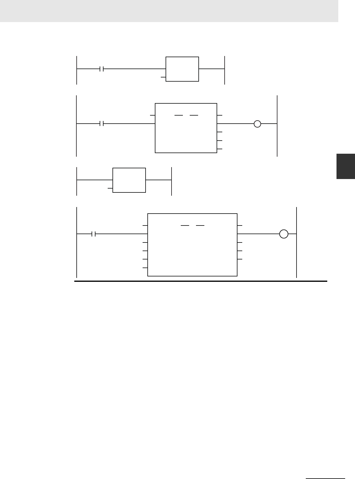
3-11
3 Axis Command Instructions
NJ/NX-series Motion Control Instructions Reference Manual (W508)
MC_MoveJog
3
Function
MC_On
Enable Status
ErrorID
PWR1
Error
MC_Power
Axis Axis
Busy
MC_Axis000
MCNo
MC
In
Pwr1_En
Pwr1_Status
0
Pwr1_Bsy
Pwr1_Err
Pwr1_ErrID
MCNo
MCR
In
0
PositiveEnable
ErrorID
MC_MoveJog_instance
Error
MC_MoveJog
Axis Axis
Busy
CommandAbortedNegativeEnable
Velocity
Acceleration
Deceleration
MC_Axis000
POS_EN
NEGA_EN
J_ERRID
VEL
ACC
DEC
J_CA
J_ERR
J_DONE
Servo turned ON.
Master control started.
Master control ended.
MC_MoveJog Instruction

3 Axis Command Instructions
3-12
NJ/NX-series Motion Control Instructions Reference Manual (W508)
• Busy (Executing) changes to TRUE as soon as PositiveEnable (Positive Direction Enable) or Nega-
tiveEnable (Negative Direction Enable) changes to TRUE.
• The axis starts deceleration as soon as PositiveEnable (Positive Direction Enable) or NegativeEnable
(Negative Direction Enable) changes to FALSE. Busy (Executing) changes to FALSE when the axis
stops completely.
• If another instruction aborts this instruction, CommandAborted changes to TRUE and Busy (Execut-
ing) changes to FALSE.
You can specify the Velocity (Target Velocity), Acceleration (Acceleration Rate), and Deceleration
(Deceleration Rate) as input variables. Input variables Velocity (Target Velocity), Acceleration (Acceler-
ation Rate), and Deceleration (Deceleration Rate) are updated in the motion only when PositiveEnable
(Positive Direction Enable) or NegativeEnable (Negative Direction Enable) changes to TRUE. There-
fore, the axis velocity will not change even if Velocity (Target Velocity) changes while PositiveEnable
(Positive Direction Enable) or NegativeEnable (Negative Direction Enable) remains TRUE.
Timing Charts
Velocity
Decelerates to a stop
when another instruction
causes an error.
Time
Deceleration
Acceleration
Target velocity
Busy
NegativeEnable
CommandAborted
Error
16#0000
ErrorID
PositiveEnable

3-13
3 Axis Command Instructions
NJ/NX-series Motion Control Instructions Reference Manual (W508)
MC_MoveJog
3
Function
Timing Chart When Target Velocity Is 0
When the Velocity (Target Velocity) is 0 and you start jogging the axis, the axis will enter continuous
operation without motion.
The following timing chart shows an example when the Velocity (Target Velocity) is 0 and you start
jogging the axis.
Timing Chart When Acceleration/Deceleration Rate Is 0
When the Acceleration (Acceleration Rate) or Deceleration (Deceleration Rate) is 0 and you start
jogging the axis, the axis will reach the target velocity without accelerating or decelerating.
The timing chart below shows an example when the Acceleration (Acceleration Rate) and Decelera-
tion (Deceleration Rate) are 0.
Velocity
Time
Busy
NegativeEnable
CommandAborted
Error
16#0000
ErrorID
PositiveEnable
Velocity
0
Velocity
Time
Busy
NegativeEnable
CommandAborted
Error
16#0000
ErrorID
PositiveEnable

3 Axis Command Instructions
3-14
NJ/NX-series Motion Control Instructions Reference Manual (W508)
Restarting with Enable in the Same Direction
If you change PositiveEnable (Positive Direction Enable) or NegativeEnable (Negative Direction
Enable) to TRUE when it is FALSE and the axis is decelerating, the axis will begin to accelerate
towards the target velocity. If you change the Velocity (Target Velocity), Acceleration (Acceleration
Rate), or Deceleration (Deceleration Rate) at this time, the new value of the input parameter is used
in operation.
The axis is not stopped, and Busy (Executing) does not change to FALSE.
The following example shows operation when PositiveEnable (Positive Direction Enable) changes to
TRUE during deceleration.
Restarting with Enable in the Opposite Direction
If you change NegativeEnable (Negative Direction Enable) to TRUE when PositiveEnable (Positive
Direction Enable) is TRUE and the axis is jogging in the positive direction, the axis will reverse its
direction and start jogging in the negative direction. When this happens, you can jog the axis with
the input variables for when NegativeEnable (Negative Direction Enable) changes to TRUE. The
input variables are Velocity (Target Velocity), Acceleration (Acceleration Rate), and Deceleration
(Deceleration Rate).
The deceleration rate before the axis direction is reversed and the acceleration rate after it is
reversed follow the input variables for when NegativeEnable (Negative Direction Enable) changes to
TRUE, regardless of the Operation Selection at Reversing axis parameter. When NegativeEnable
(Negative Direction Enable) is TRUE and the axis is jogging in the negative direction, the same
operation occurs when PositiveEnable (Positive Direction Enable) changes to TRUE.
If NegativeEnable (Negative Direction Enable) changes to TRUE while PositiveEnable (Positive
Direction Enable) is TRUE, the axis starts jogging in the negative direction. In this case, the axis will
not jog in the positive direction even if NegativeEnable (Negative Direction Enable) changes to
FALSE. To jog the axis in the positive direction, change PositiveEnable (Positive Direction Enable) to
FALSE, and then back to TRUE again. The same operation applies to the opposite case.
The following example shows an operation example when NegativeEnable (Negative Direction
Enable) changes to TRUE after PositiveEnable (Positive Direction Enable) changes to TRUE.
Re-execution of Motion Control Instructions
Velocity
Time
Busy
NegativeEnable
CommandAborted
Error
ErrorID
PositiveEnable
Velocity Velocity1 Velocity2
Velocity1
Velocity2
16#0000

3-15
3 Axis Command Instructions
NJ/NX-series Motion Control Instructions Reference Manual (W508)
MC_MoveJog
3
Function
For details on multi-execution of motion control instructions, refer to the NJ/NX-series CPU Unit Motion
Control User’s Manual (Cat. No. W507) or NY-series Industrial Panel PC / Industrial Box PC Motion
Control User’s Manual (Cat. No. W559).
If an error occurs during instruction execution, Error will change to TRUE and the axes will stop. You
can find out the cause of the error by referring to the value output by ErrorID (Error Code).
Timing Chart When Error Occurs
Error Codes
Refer to A-1 Error Codes for instruction errors.
Multi-execution of Motion Control Instructions
Errors
Busy
NegativeEnable
CommandAborted
Error
16#0000
ErrorID
PositiveEnable
Velocity
Time
Error code
Busy
NegativeEnable
CommandAborted
Error
ErrorID
PositiveEnable

3 Axis Command Instructions
3-16
NJ/NX-series Motion Control Instructions Reference Manual (W508)
MC_Home
The MC_Home instruction operates the motor to determine home. It uses the limit signals, home prox-
imity signal, and home signal.
* Refer to A-1 Error Codes.
Instruction Name FB/FUN Graphic expression ST expression
MC_Home Home FB MC_Home_instance (
Axis :=parameter,
Execute :=parameter,
Done =>parameter,
Busy =>parameter,
CommandAborted
=>parameter,
Error =>parameter,
ErrorID =>parameter
);
Variables
Input Variables
Name Meaning Data type Valid range Default Description
Execute Execute BOOL TRUE or FALSE FALSE The instruction is executed when Exe-
cute changes to TRUE.
Output Variables
Name Meaning Data type Valid range Description
Done Done BOOL TRUE or FALSE TRUE when the instruction is completed.
Busy Executing BOOL TRUE or FALSE TRUE when the instruction is acknowledged.
CommandAborted Command
Aborted
BOOL TRUE or FALSE TRUE when the instruction is aborted.
Error Error BOOL TRUE or FALSE TRUE while there is an error.
ErrorID Error Code WORD
*
Contains the error code when an error occurs.
A value of 16#0000 indicates normal execution.
MC_Home_instance
Axis Axis
Execute
Error
ErrorID
CommandAborted
MC_Home
Done
Busy

3-17
3 Axis Command Instructions
NJ/NX-series Motion Control Instructions Reference Manual (W508)
MC_Home
3
Function
Output Variable Update Timing
* Specify a user-defined Axis Variable that was created in the Axis Basic Settings of the Sysmac Studio (default: MC_Axis***)
or a system-defined axis variable name (_MC_AX[*], _MC1_AX[*], or _MC2_AX[*]).
• Homing starts when Execute changes to TRUE for the axis specified in Axis.
• Set the parameters used by the home instruction in the axis parameters.
• There are 10 Homing Operation Modes for the home instruction.
Set the desired method in axis parameter Homing Method in the Sysmac Studio.
Precautions for Correct UsePrecautions for Correct Use
Refer to Precautions for Master and Auxiliary Axes in Synchronized Control on page 1-6 for pre-
cautions on the master axis.
Mapping Data Objects
To use the MC_Home instruction, map the following object data in the Detailed Settings Area of the
Axis Basic Settings Display of the Sysmac Studio. However, setting is not required for Homing Oper-
ation Modes 11, 12, and 14.
• Touch probe function (60B8 hex)
• Touch probe status (60B9 hex)
• Touch probe pos1 pos value (60BA hex)
If even one of the required objects is not set, a Process Data Object Setting Missing error (error
code 3461 hex) occurs.
Name Timing for changing to TRUE Timing for changing to FALSE
Done When the instruction is completed. • When Execute is TRUE and changes to
FALSE.
• After one period when Execute is FALSE.
Busy When Execute changes to TRUE. • When Done changes to TRUE.
• When Error changes to TRUE.
• When CommandAborted changes to TRUE.
CommandAborted • When this instruction is aborted because
another motion control instruction was
executed with the Buffer Mode set to
Aborting.
• When this instruction is canceled due to
an error.
• When this instruction is executed while
there is an error.
• When you start this instruction during
MC_Stop instruction execution.
• When Execute is TRUE and changes to
FALSE.
• After one period when Execute is FALSE.
Error When there is an error in the execution con-
ditions or input parameters for the instruc-
tion.
When the error is cleared.
In-Out Variables
Name Meaning Data type Valid range Description
Axis Axis _sAXIS_REF ---
Specify the axis.
*
Function

3 Axis Command Instructions
3-18
NJ/NX-series Motion Control Instructions Reference Manual (W508)
For details on mapping data objects, refer to 2-3 PDO Mapping and to the NJ/NX-series CPU Unit
Motion Control User’s Manual (Cat. No. W507) or NY-series Industrial Panel PC / Industrial Box PC
Motion Control User’s Manual (Cat. No. W559).
Refer to I/O Entry Mappings in the NX-series Position Interface Units User’s Manual (Cat. No. W524)
for information on using the NX-series Position Interface Units.
Set the input signals, such as the home proximity signal, that are used by the home instruction in the
OMRON 1S-series Servo Drive.
Refer to the information on connecting to the Servo Drive in the NJ/NX-series CPU Unit Motion Control
User’s Manual (Cat. No. W507) or NY-series Industrial Panel PC / Industrial Box PC Motion Control
User’s Manual (Cat. No. W559) and information on general input signals in the AC Servomotors/Servo
Drives 1S-series with Built-in EtherCAT Communications User’s Manual (Cat. No. I586) for details on
how to set the input signals.
Set the input signals, such as the home proximity signal, that are used by the home instruction in the
OMRON G5-series Servo Drive.
Refer to the information on connecting to the Servo Drive in the NJ/NX-series CPU Unit Motion Control
User’s Manual (Cat. No. W507) or NY-series Industrial Panel PC / Industrial Box PC Motion Control
User’s Manual (Cat. No. W559) and information on sequence I/O signals in the AC Servomotors/Servo
Drives G5-series with Built-in EtherCAT Communications User’s Manual (Cat. No. I576) or the AC Ser-
vomotors/Servo Drives G5-series with Built-in EtherCAT Communications Linear Motor Type User’s
Manual (Cat. No. I577) for details on how to set the input signals.
Refer to the NX-series Position Interface Units User’s Manual (Cat. No. W524) for information on setting
the NX-series Position Interface Units.
Settings for OMRON 1S-series Servo Drives
Settings for OMRON G5-series Servo Drives
Settings for NX-series Position Interface Units

3-19
3 Axis Command Instructions
NJ/NX-series Motion Control Instructions Reference Manual (W508)
MC_Home
3
Function
You can select any of the ten operations to define home. For details on the operations, refer to Function
on page 3-17.
• Proximity reverse turn/home proximity input OFF
• Proximity reverse turn/home proximity input ON
• Home proximity input OFF
• Home proximity input ON
• Limit input OFF
• Proximity reverse turn/home input mask distance
• Limit inputs only
• Proximity reverse turn/holding time
• No home proximity input/holding home input
• Zero position preset
The following tables shows the homing parameters that are used for each Homing Operation Mode.
(Yes: Parameter is used, No: Parameter is not used.)
Refer to Homing Definition Operation on page 3-23 for details on operation in the Homing Modes.
Homing Operation Modes
Homing parameters
Homing Operation Mode
Home Input Signal
Homing Start Direction
Home Input Detection Direction
Operation Selection at Positive Limit Input
Operation Selection at Negative Limit Input
Homing Velocity
Homing Approach Velocity
Homing Acceleration
Homing Deceleration
Homing Jerk
Home Input Mask Distance
Home Offset
Homing Holding Time
Homing Compensation Value
Homing Compensation Velocity
Proximity reverse turn/home prox-
imity input OFF
Ye s Ye s Ye s Ye s Ye s Ye s Ye s Ye s Ye s Ye s N o Ye s N o Ye s Ye s
Proximity reverse turn/home prox-
imity input ON
Ye s Ye s Ye s Ye s Ye s Ye s Ye s Ye s Ye s Ye s N o Ye s N o Ye s Ye s
Home proximity input OFF
Ye s Ye s Ye s Ye s Ye s Ye s Ye s Ye s Ye s Ye s N o Ye s N o Ye s Ye s
Home proximity input ON
Ye s Ye s Ye s Ye s Ye s Ye s Ye s Ye s Ye s Ye s N o Ye s N o Ye s Ye s
Limit input OFF
Ye s Ye s Ye s Ye s Ye s Ye s Ye s Ye s Ye s Ye s N o Ye s N o Ye s Ye s
Proximity reverse turn/home input
mask distance
Ye s Ye s Ye s Ye s Ye s Ye s Ye s Ye s Ye s Ye s Ye s Ye s N o Ye s Ye s
Limit inputs only
N o Ye s Ye s Ye s Ye s Ye s Ye s Ye s Ye s Ye s N o Ye s N o Ye s Ye s
Proximity reverse turn/holding time
N o Ye s Ye s Ye s Ye s Ye s Ye s Ye s Ye s Ye s N o Ye s Ye s Ye s Ye s
No home proximity input/holding
home input
Ye s Ye s Ye s Ye s Ye s Ye s Ye s Ye s Ye s Ye s N o Ye s N o Ye s Ye s
Zero position preset
No No No No No No No No No No No Yes No No No

3 Axis Command Instructions
3-20
NJ/NX-series Motion Control Instructions Reference Manual (W508)
Additional Information
If you use NX-series Position Interface Units, do not select holding for the Homing Operation
Mode. Refer to the NX-series Position Interface Units User’s Manual (Cat. No. W524) for details.
• Select the operation when the axis reaches a limit input in the operating direction during homing:
reverse the axis and continue with homing, or do not reverse the axis, create an error, and stop the
axis. To reverse the axis, also select the stopping method.
• An error occurs and the axis stops if the axis is set to reverse direction, and the limit signal in the
home input detection direction turns ON when traveling at the homing approach velocity. However, if
the homing operation mode is 13 (no home proximity input/holding home input), which does not use
proximity signals, no error will occur and the axis will not stop.
• An error occurs and the axis stops if the axis is set to reverse direction or the limit input operation in
both directions and home cannot be detected after moving from the limit input opposite to the home
input detection direction to the other limit input.
Operation Selection at Positive Limit Input and Operation Selection
at Negative Limit Input
ON
OFF
ON
OFF
ON
OFF
Homing velocity
Stops.
Start
Homing approach velocity
Home instruction
Limit in detection direction
Limit in direction opposite
to detection direction
Home proximity input signal
ON
OFF
ON
OFF
ON
OFF
Stops.
Start
Homing approach velocity
Homing velocity
Home instruction
Limit in detection direction
Limit in direction opposite
to detection direction
Home proximity input signal

3-21
3 Axis Command Instructions
NJ/NX-series Motion Control Instructions Reference Manual (W508)
MC_Home
3
Function
Select the direction in which the axis starts moving when homing is started. If homing starts while the
home proximity signal is ON in a Homing Operation Mode that includes reversal operation, the axis
starts motion in the direction opposite to the home input detection direction (regardless of the setting of
the homing start direction).
There are four Homing Operation Modes that include reversal operation for a reverse turn. These are
listed below.
• 0: Proximity reverse turn/home proximity input OFF
• 1: Proximity reverse turn/home proximity input ON
• 9: Proximity reverse turn/home input mask distance
• 12: Proximity reverse turn/holding time
Homing Start Direction
(1), (3): The home proximity signal is OFF, so the axis starts moving in the homing start direction.
(2): The home proximity signal is ON, so the axis starts moving in the direction opposite to the
home input detection direction.
(1), (3): The home proximity signal is OFF, so the axis starts moving in the homing start direction.
(2): The home proximity signal is ON, so the axis starts moving in the direction opposite to the
home input detection direction.
ON
OFF
Positive direction
Start
Start
Start
Negative direction
Operation command
Home proximity input signal
Homing start direction: Positive
Home input detection direction: Positive
(1) (3)
(2)
ON
OFF
Start
Positive direction
Start
Start
Negative direction
Operation command
Home proximity input signal
Homing start direction: Negative
Home input detection direction: Negative
(1) (3)
(2)

3 Axis Command Instructions
3-22
NJ/NX-series Motion Control Instructions Reference Manual (W508)
Select the direction when home input is detected.
The following timing chart shows the operation when the home input detection direction is FALSE (pos-
itive direction).
The following timing chart shows the operation when the home input detection direction is TRUE (nega-
tive direction).
Set the feed distance when you set the Homing Operation Mode to 9 (proximity reverse turn/home input
mask distance). For details on the operation, refer to 9: Proximity Reverse Turn/Home Input Mask Dis-
tance Operation on page 3-26.
Set the homing compensation value that is applied after the home is detected. Set the travel velocity in
the Homing Compensation Velocity. For details on the operation, refer to Homing Compensation on
page 3-32.
The Home Position Offset is used to preset the actual position after homing is completed. The current
value is the value set for the Home Position Offset.
Home Input Detection Direction
Home Input Mask Distance
Homing Compensation Value
Home Position Offset
OFF
ON
OFF
ON
Positive direction
Stops.
Homing approach velocity
Start
Negative direction
Homing velocity
Operation command
Home input signal
Home proximity input signal
Operation Example: Proximity Reverse Turn/Home Proximity Input OFF
OFF
ON
OFF
ON
Homing velocity
Homing approach velocity
Positive direction
Start
Stops.
Negative direction
Homing velocity
Operation command
Home input signal
Home proximity input signal
Operation Example: Proximity Reverse Turn/Home Proximity Input OFF

3-23
3 Axis Command Instructions
NJ/NX-series Motion Control Instructions Reference Manual (W508)
MC_Home
3
Function
This is the high velocity during homing.
This is the proximity velocity during homing.
This is the velocity when you set a homing compensation value. For details on the operation, refer to
Homing Compensation on page 3-32.
Homing Definition Operation
This section describes the 10 Homing Operation Modes.
0: Proximity Reverse Turn/Home Proximity Input OFF Operation
1
The axis starts at the homing velocity. When the home proximity input signal turns ON, the axis
starts decelerating to the homing approach velocity.
2
After the axis reaches the homing approach velocity, the axis stops at the first home input signal
after the home proximity input signal turns OFF. This defines home.
• If you start homing while the home proximity input signal is ON, the operation will start at the hom-
ing velocity in the direction opposite to the home input detection direction. After the home proxim-
ity input turns OFF, the homing operation will start at the homing velocity in the home input
detection direction.
• Homing is started and home is defined when the home input signal turns ON after the home prox-
imity input signal turns ON and OFF while the velocity is below the homing approach velocity.
1: Proximity Reverse Turn/Home Proximity Input ON Operation
1
The axis starts at the homing velocity. When the home proximity input signal turns ON, the axis
starts decelerating to the homing approach velocity.
2
After the axis reaches the homing approach velocity, the axis stops at the first home input signal.
This defines home.
After the home proximity input signal turns ON, its status does not affect operation.
Homing Velocity
Homing Approach Velocity
Homing Compensation Velocity
Instruction Details
ON
OFF
ON
OFF
Positive direction
Negative direction
Start
Stops
Homing velocity
Homing approach velocity
Home proximity input signal
Home input signal
Command output
Home input detection direction
Homing velocity

3 Axis Command Instructions
3-24
NJ/NX-series Motion Control Instructions Reference Manual (W508)
• If you start homing while the home proximity input signal is ON, the operation will start at the hom-
ing velocity in the direction opposite to the home input detection direction. After the home proxim-
ity input turns OFF, the homing operation will start at the homing velocity in the home input
detection direction.
• Homing is started and home is defined when the home input signal turns ON after the home prox-
imity input signal turns ON while the velocity is below the homing approach velocity.
4: Operation for Home Proximity Input OFF
1
When the home proximity input signal turns ON, the axis starts decelerating to the homing
approach velocity.
2
After the axis reaches the homing approach velocity, the axis stops at the first home input signal
after the home proximity input signal turns OFF. This defines home.
• If you start homing while the home proximity input signal is ON, the axis performs the following
operation depending on the setting of the homing start direction.
Homing Start Direction Same as Home Input Detection Direction
The axis does not perform a reverse turn operation and homing starts in the home input detection
direction at the homing approach velocity.
Start
Stops.
Homing approach velocity
Homing velocity
Negative direction
Positive direction
Homing velocity
Command output
Home input signal
Home proximity input signal
Home input detection direction
ON
OFF
ON
OFF
Start
Homing approach velocity
Start
Start
Stops.
Homing velocity
Positive direction
Stops.
Homing approach velocity
Positive direction
Stops.
Positive direction
Homing approach velocity
Negative direction
Homing velocity
Negative direction
Negative direction
Homing velocity
Homing start direction
Homing start direction
Home input signal
Home proximity input signal
Negative limit input signal
Home input detection direction
ON
OFF
ON
OFF
ON
OFF

3-25
3 Axis Command Instructions
NJ/NX-series Motion Control Instructions Reference Manual (W508)
MC_Home
3
Function
Homing Start Direction Different from Home Input Detection Direction
Operation starts in the homing start direction at the homing velocity, regardless of the status of the
home proximity input signal. If you set the operation at the limit input in the homing start direction to
reverse direction, the axis reverses direction when limit input is detected and performs a homing
operation in the home input detection direction.
• Homing is started and home is defined when the home input signal turns ON after the home prox-
imity input signal turns ON and OFF while the velocity is below the homing approach velocity.
5: Home Proximity Input ON Operation
1
When the home proximity input signal turns ON, the axis starts decelerating to the homing
approach velocity.
2
After the axis reaches the homing approach velocity, the axis stops at the first home input signal.
This defines home.
After the home proximity input signal turns ON, its status does not affect operation.
• If you start homing while the home proximity input signal is ON, the axis performs the following
operation depending on the setting of the homing start direction.
Homing Start Direction Same as Home Input Detection Direction
The axis does not perform a reverse turn operation and homing starts in the home input detection
direction at the homing velocity.
Homing Start Direction Different from Home Input Detection Direction
Operation starts in the homing start direction at the homing velocity, regardless of the status of the
home proximity input signal. If you set the operation at the limit input in the homing start direction to
reverse direction, the axis reverses direction when limit input is detected and performs a homing
operation in the home input detection direction.
• Homing is started and home is defined when the home input signal turns ON after the home prox-
imity input signal turns ON while the velocity is below the homing approach velocity.
Stop
Homing velocity
Start
StartStop
Homing approach velocity
Stop
Homing approach velocity
Start
Positive direction
Positive direction
Positive direction
Negative direction
Homing start direction
Homing velocity
Negative direction
Homing start direction
Negative direction
Homing velocity
Home input signal
Home proximity input signal
Negative limit input signal
Home input detection direction
ON
OFF
ON
OFF
ON
OFF
ON
OFF
Positive limit input signal
Homing approach velocity

3 Axis Command Instructions
3-26
NJ/NX-series Motion Control Instructions Reference Manual (W508)
8: Operation for Limit input OFF
1
The axis starts at the homing velocity. When the limit signal in the direction opposite to the home
input detection direction turns ON, the axis starts decelerating to the homing approach velocity.
2
After the axis reaches the homing approach velocity, the axis stops at the first home input signal
after the limit signal turns OFF. This defines home.
• If you perform homing while the limit input on the opposite side of the home input detection direc-
tion is ON, the homing operation starts at the home approach velocity in the home input detection
direction.
• Homing is started and home is defined when the home input signal turns ON after the limit signal
in the direction opposite to the home input detection direction turns ON and OFF again while the
velocity is below the homing approach velocity.
9: Proximity Reverse Turn/Home Input Mask Distance Operation
1
The axis starts at the homing velocity. When the home proximity input signal turns ON, the axis
starts decelerating to the homing approach velocity.
2
The axis moves by the home input mask distance after the home proximity input signal turns ON
and stops at the first home input signal. This defines home.
After the home proximity input signal turns ON, its status does not affect operation. If the speci-
fied travel distance is too short and travel would be completed before the axis decelerates to the
homing approach velocity, an Invalid Home Input Mask Distance error (error code: 742B hex)
occurs when you start homing.
• If you start homing while the home proximity input signal is ON, the operation will start at the hom-
ing velocity in the direction opposite to the home input detection direction. After the home proxim-
ity input signal turns OFF, the homing operation will start at the homing approach velocity in the
home input detection direction.
Start
Stops.
Homing approach velocity
Stops.
Homing approach velocity
Negative direction
Start
Negative direction
Positive direction
Positive direction
Homing velocity
Command output
Home input signal
Negative limit input signal
Home input detection direction
ON
OFF
ON
OFF
After the proximity input, motion is
according to the home input mask distance.
Stops.
Homing approach velocity
Start
Positive direction
Negative direction
Homing velocity
Command output
Home input signal
Home proximity input signal
Home input detection direction
ON
OFF
ON
OFF

3-27
3 Axis Command Instructions
NJ/NX-series Motion Control Instructions Reference Manual (W508)
MC_Home
3
Function
• Homing is started and home is defined when the home input signal turns ON after the axis travels
the home input mask distance after the home proximity input signal turns ON while the velocity is
below the homing approach velocity.
11: Operation for Limit Inputs Only
1
The axis starts at the homing velocity. When the limit signal in the direction opposite to the home
input detection direction turns OFF, the axis decelerates to a stop.
2
After the axis stops, the axis moves in the other direction at the homing velocity and decelerates
to a stop when the limit signal turns ON.
3
After the axis stops, the axis moves in the other direction at the homing approach velocity. The
position where the limit signal turns OFF is defined as home and an immediate stop is per-
formed (i.e., a stop using remaining pulses). The axis does not return to the home position.
• If you use only the limit signals to perform homing, the point at which the limit signal turns OFF
during operation in the home input detection direction is set as the home detection position.
• If you start homing while the limit signal in the home input detection direction is ON, the operation
will start at the homing velocity in the direction opposite to the home input detection direction.
When the limit signal in the direction opposite to the home input detection direction turns ON, the
axis decelerates to a stop.
• Even if the limit signal turns OFF before the axis decelerates to a stop after the limit signal is
detected, home is not defined and the axis continues to decelerate. In this case, no error will
occur.
• Home is defined if the limit signal turns OFF before the homing approach velocity is reached after
the axis reverses or after starting while the limit signal is input.
Differences between Homing Operation Mode 11 and Other Homing Operation Modes
For Homing Operation Mode 11, the MC Function Module detects when the limit signal turns OFF to
define home. It differs from a Homing Operation Mode that uses the home input as an external latch
signal in the following ways.
Make sure that you understand these differences with other Homing Operation Modes before you
use Homing Operation Mode 11.
Positive direction
Positive direction
Positive direction
Start
Start
Negative direction
Homing velocity
Negative direction
Homing velocity
Negative direction
Positive limit input signal
Negative limit input signal
Home input detection direction
Range of movement
Stops using
remaining pulses.
Start
ON
OFF
ON
OFF
Homing approach velocity
Homing approach velocity
Homing approach velocity
Home
Home
Home
Stops using
remaining pulses.
Stops using
remaining pulses.

3 Axis Command Instructions
3-28
NJ/NX-series Motion Control Instructions Reference Manual (W508)
• The MC Function Module detects the limit input without an external latch function, such as one
provided by a Servo Drive. MC Function Module processing is the processing performed at the
primary period interval for the primary periodic task and at the task period of the priority-5 periodic
task for the priority-5 periodic task. Therefore, the precision of the home definition will depend on
the homing approach velocity and the control period of the primary periodic task or priority-5 peri-
odic task.
• The axis does not return to the home position. If the homing compensation value is 0, processing
for homing will end with the axis at a different position (i.e., not at home).
• Homing compensation is not performed if the homing compensation value is set to 0. If the hom-
ing compensation value is 0, processing for homing ends with the axis at a different position (i.e.,
not at home), as explained above. If the homing compensation value is not 0, then homing com-
pensation is performed with the homing compensation value as a relative position from home in
the same way as for other homing operation modes.
• The home offset is used to change the position of home. If the stop position is offset from home by
distance D, as shown in the following figure, the position after the completion of processing for
homing will be L + D if the home offset is L and the homing compensation value is 0.
Precautions for Correct UsePrecautions for Correct Use
• After the OFF limit signal is detected, the limit signal in the opposite direction from the home
input detection direction is ignored while stopping for the remaining pulses until homing com-
pensation is started.
• If the homing compensation value is 0 and the limit input signal in the home input detection
direction turns ON immediately after home is defined, set a homing compensation value to
return past the limit signal input position.
Application Example for Homing Operation Mode 11
If, as shown below, there is not sufficient space to install both a negative limit signal and home sig-
nal, you can use the negative limit signal to perform the functions of both the limit signal and home
signal.
D
0D
L L + D
Range of stopping for remaining pulses
Before home offset:
After home offset:
Range where negative
limit signal is ON
Workpiece
Operating direction
Negative limit signal
(home)
Positive limit signal

3-29
3 Axis Command Instructions
NJ/NX-series Motion Control Instructions Reference Manual (W508)
MC_Home
3
Function
12: Proximity Reverse Turn/Holding Time Operation
1
The axis starts at the homing velocity. When the home proximity input signal turns ON, the axis
starts decelerating to the homing approach velocity.
The torque limit at the start of holding differs between OMRON 1S-series as well as G5-series
Servo Drives and other Servo Drives as shown below.
Refer to Holding Operation for OMRON 1S-series Servo Drives on page 3-32 or Holding Opera-
tion for OMRON G5-series Servo Drives on page 3-33 for information on the holding operation.
2
Home is defined when the set time elapses.
After the home proximity input signal turns ON, its status does not affect operation.
• If you start homing while the home proximity input signal is ON, the operation will start at the hom-
ing velocity in the direction opposite to the home input detection direction. After the home proxim-
ity input signal turns OFF, the homing operation will start at the homing approach velocity in the
home input detection direction.
• Releasing the torque limit also differs between OMRON 1S-series as well as G5-series Servo
Drives and other Servo Drives.
• An error will not occur and home is defined even if the holding time elapses after the home prox-
imity input signal is detected and before velocity reaches the homing approach velocity.
• Home is also defined if the holding time elapses after the home proximity input signal turns ON
before the homing approach velocity is reached.
1S-series, G5-series: Automatically applies torque limits.
Other Servo Drives: Apply torque limits according to a setting.
1S-series, G5-series: Automatically released when the axis moves in the direction oppo-
site to homing for the first time after homing.
Other Servo Drives: If a torque limit is used, release the torque limit when the axis
moves in the direction opposite to homing for the first time after
homing. Use the EC_CoESDOWrite (CoE SDO Write) instruction
to change the torque limit.
Positive direction
Command torque from previous operation
Torque limit is continued even after the set time elapses.
Torque limit
Homing velocity
Stops.
Start
Negative direction
Homing approach velocity
Homing velocity
Positive direction
Stops.Start
Negative direction
Homing approach velocity
Home is defined upon elapse of the set time.
Homing velocity
Command output
Home proximity input signal
Home input detection direction
ON
OFF

3 Axis Command Instructions
3-30
NJ/NX-series Motion Control Instructions Reference Manual (W508)
13: No Home Proximity Input/Holding Home Input Operation
1
The axis starts at the homing approach velocity.
The torque limit at the start of holding differs between OMRON 1S-series as well as G5-series
Servo Drives and other Servo Drives as shown below.
Refer to Holding Operation for OMRON 1S-series Servo Drives on page 3-32 or Holding Opera-
tion for OMRON G5-series Servo Drives on page 3-33 for information on the holding operation.
2
Home is defined when the home input turns ON.
• Releasing the torque limit also differs between OMRON 1S-series as well as G5-series Servo
Drives and other Servo Drives.
• Home is also defined if the home input signal turns ON before the homing approach velocity is
reached after homing starts.
Precautions for Correct UsePrecautions for Correct Use
For an OMRON G5-series Linear Motor Type Servo Drive with built-in EtherCAT communica-
tions, the Z-phase input cannot be mapped to a PDO. Therefore, if you use Homing Operation
Mode 13 (no home proximity input/holding home input), which can use a Z-phase input mapped
to a PDO, do not select the Z-phase input for the home input signal.
1S-series, G5-series: Automatically applies torque limits.
Other Servo Drives: A torque limit imposed as required.
1S-series, G5-series: Automatically released when the axis moves in the direction oppo-
site to homing for the first time after homing.
Other Servo Drives: If a torque limit is used, release the torque limit when the axis
moves in the direction opposite to homing for the first time after
homing. Use the EC_CoESDOWrite (CoE SDO Write) instruction
to change the torque limit.
Positive direction
Homing approach velocity
Stops.
Start
Command torque from previous operation
Torque limit
Negative direction
Command output
Home input signal
Home input detection direction
ON
OFF

3-31
3 Axis Command Instructions
NJ/NX-series Motion Control Instructions Reference Manual (W508)
MC_Home
3
Function
14: Zero Position Preset Operation
The command current position is set to the home position offset to define home. Also, the following
error between the command current position and the actual position is retained.
Axis Stopping Method and In-position Check When Homing
The axis is stopped with the following procedure when homing.
1
The actual position where the home input signal was detected is latched and the axis stops
immediately.
2
After the immediate stop, the axis moves with absolute travel in the reverse direction to the posi-
tion that was latched in step 1.
• Waiting for the in-position state is always performed for this instruction regardless of the setting of
the In-position Check Time axis parameter.
Be particularly careful when performing absolute travel to the home input signal detection position
if the In-position Check Time is set to 0 because the instruction will continue waiting for the in-
position status. Make sure that the signal is received within the in-position range. In-position wait-
ing is not performed for the homing compensation value operation even if the in-position check
time is set to 0. The status of in-position waiting can be checked with the InPosWaiting (In-position
Waiting) system-defined variable for motion control.
Error
ErrorID
Execute
Done
Busy
CommandAborted
16#0000
0
-2
Actual current position
Command current position
Homed (Home Defined)
Homing
5
3
ON
OFF
ON
OFF
Homing
compensation
velocity
In-position check applied.
Homing
compensation value
Stops.
Absolute travel to position where
home input signal was detected
Immediate stop
Actual position latch
Start
Homing approach velocity
Velocity
Homing velocity
Home input signal
Home proximity input signal

3 Axis Command Instructions
3-32
NJ/NX-series Motion Control Instructions Reference Manual (W508)
Homing Compensation
When you set a homing compensation value, the axis will move by the homing compensation value
after the home input is detected to define home. Adjusting the workpiece is sometimes difficult after
home has been defined in the mechanical system. You can use the homing compensation to fine-
tune the position of home after it is defined. The travel velocity at this time is the homing compensa-
tion velocity. The axis starts moving 500 ms after it stopped when the home input was detected.
The sign of the homing compensation value indicates the direction relative to the coordinate axis. If
it is negative, the axis moves in the negative direction.
Override Factors
Overrides are disabled for this instruction.
Automatic Control of Torque Limit
If you are using an OMRON 1S-series Servo Drive or G5-series Servo Drive, and you select either
Proximity Reverse Turn/Holding Time Operation (12) or No Home Proximity Input/Holding Home
Input Operation (13) for the homing operation, the torque limit will be automatically started in the
holding direction.
The torque limit is released when the axis moves in the direction opposite to the home input detec-
tion direction.
The torque limit is automatically released at the following times.
• When the Servo is turned OFF (Servo Unlock)
• When the Cyclic Synchronous Position (CSP) Control Mode is changed to another control mode.
During the homing operation, torque limits are released for operation in the direction opposite to the
home input detection direction. For example, if the reversal operation direction at a limit input is in
the direction opposite to the home input detection direction, the torque limit is released when the
reversal operation is completed. If the operation direction reverses again and becomes the home
input detection direction, the torque limit will be enabled again.
Holding Operation for OMRON 1S-series Servo Drives
Torque limits that are set in the Servo Drive in advance are used for the Proximity Reverse
Turn/Holding Time (12) or No Home Proximity Input/Holding Home Input (13) Homing Operation
Modes to automatically start torque control in the home input detection direction.
Precautions for Correct UsePrecautions for Correct Use
The automatic torque limit function of the MC_Home instruction is not used for servo drives from
other manufacturers.
Use the MC_SetTorqueLimit instruction, SDO communications, or support software to set suit-
able values.
ON
OFF
ON
OFF
500 ms
Start Stops.
Homing
compensation
value
Homing
compensation
velocity
Homing approach velocity
Homing velocity
Velocity
Home input signal
Home proximity input signal

3-33
3 Axis Command Instructions
NJ/NX-series Motion Control Instructions Reference Manual (W508)
MC_Home
3
Function
Additional Information
• The torque limits are continued even after a normal completion of homing.
• The torque limits are automatically released when an instruction that moves the axis in the
opposite direction is executed.
Settings for OMRON 1S-series Servo Drives
To use the holding operation, you must set the Torque Limit - Switch Selection (3330-01 hex) for the
1S-series Servo Drive with the Sysmac Studio.
• Set the Torque Limit - Switch Selection to 2 to apply a torque limit in the home input detection
direction during the holding operation for homing and to use the torque limit directions and values
that are set with the MC_SetTorqueLimit instruction for other operation.
In that case, the values of the input variables to the MC_SetTorqueLimit instruction are ignored
during the holding operation for homing.
• If the Torque Limit - Switch Selection is set to 0, the values of the input variables to the MC_Set-
TorqueLimit instruction are always used. You must set torque limits that are suitable for both for
the holding operation during homing and for other operations.
For details on torque limits, refer to MC_SetTorqueLimit on page 3-323.
Also, for details on the settings of 1S-series Servo Drives, refer to the AC Servomotors/Servo Drives
1S-series with Built-in EtherCAT Communications User’s Manual (Cat. No. I586).
Holding Operation for OMRON G5-series Servo Drives
Torque limits that are set in the Servo Drive in advance are used for the Proximity Reverse
Turn/Holding Time (12) or No Home Proximity Input/Holding Home Input (13) Homing Operation
Modes to automatically start torque control in the home input detection direction.
Precautions for Correct UsePrecautions for Correct Use
The automatic torque limit function of the MC_Home instruction is not used for servo drives from
other manufacturers. Use the MC_SetTorqueLimit instruction, SDO communications, or support
software to set suitable values.
Torque Limit - Switch Selection (3330-01 hex)
2 0
Positive
Torque Limit
Homing The Torque Limit - Positive Torque
Limit Value 2 (3330-05 hex) for the
Servo Drive is used.
The PositiveValue (Positive Torque
Limit) for the MC_SetTorqueLimit
instruction is used.
Operations
other than
Homing
The PositiveValue (Positive Torque
Limit) for the MC_SetTorqueLimit
instruction is used.
Negative
Torque Limit
Homing The Torque Limit - Negative Torque
Limit Value 2 (3330-06 hex) for the
Servo Drive is used.
The NegativeValue (Negative Torque
Limit) for the MC_SetTorqueLimit
instruction is used.
Operations
other than
Homing
The NegativeValue (Negative Torque
Limit) for the MC_SetTorqueLimit
instruction is used.

3 Axis Command Instructions
3-34
NJ/NX-series Motion Control Instructions Reference Manual (W508)
Additional Information
• The torque limits are continued even after a normal completion of homing.
• The torque limits are automatically released when an instruction that moves the axis in the
opposite direction is executed.
Settings for OMRON G5-series Servo Drives
To use the holding operation, you must use the support software of the Servo Drive to set the Torque
Limit Selection (3521 hex) in the G5-series Servo Drive.
• Set the Torque Limit Selection to 6 to apply a torque limit in the home input detection direction
during the holding operation for homing and to use the torque limit directions and values that are
set with the MC_SetTorqueLimit instruction for other operation. In that case, the values of the
input variables to the MC_SetTorqueLimit instruction are ignored during the holding operation for
homing.
• If the Torque Limit Selection is set to 4, the values of the input variables to the MC_SetTorqueLimit
instruction are always used. You must set torque limits that are suitable for both for the holding
operation during homing and for other operations.
For details on torque limits, refer to MC_SetTorqueLimit on page 3-323. For the settings for the G5-
series Servo Drive, refer to the AC Servomotors/Servo Drives G5-series with Built-in EtherCAT
Communications User’s Manual (Cat. No. I576) or the AC Servomotors/Servo Drives G5-series with
Built-in EtherCAT Communications Linear Motor Type User’s Manual (Cat. No. I577).
Monitoring Following Error during Holding Operation
The following error is not monitored during the holding operation for homing.
For details on monitoring the following error, refer to the NJ/NX-series CPU Unit Motion Control
User’s Manual (Cat. No. W507) or NY-series Industrial Panel PC / Industrial Box PC Motion Control
User’s Manual (Cat. No. W559).
Torque Limit Selection (3521 hex)
6 (recommended) 4
Positive Torque
Limit
Homing Torque Limit 3 (3525 hex) is used. The smaller of the PositiveValue
(Positive Torque Limit) for the MC_-
SetTorqueLimit instruction and
Torque Limit 1 (3013 hex) is used.
Operations other
than Homing
The smaller of the PositiveValue
(Positive Torque Limit) for the MC_-
SetTorqueLimit instruction and
Torque Limit 1 (3013 hex) is used.
Negative Torque
Limit
Homing Torque Limit 4 (3526 hex) is used. The smaller of the NegativeValue
(Negative Torque Limit) for the
MC_SetTorqueLimit instruction and
Torque Limit 2 (3522 hex) is used.
Operations other
than Homing
The smaller of the NegativeValue
(Negative Torque Limit) for the
MC_SetTorqueLimit instruction and
Torque Limit 2 (3522 hex) is used.

3-35
3 Axis Command Instructions
NJ/NX-series Motion Control Instructions Reference Manual (W508)
MC_Home
3
Function
The following charts show the timing of homing.
No Homing Compensation
With Homing Compensation
Timing Charts
Done
Busy
CommandAborted
Error
16#0000
ErrorID
Execute
Homing
Time
Velocity
Homed (Home Defined)
Done
Busy
CommandAborted
Error
16#0000
ErrorID
Execute
Homing
Time
Velocity
Homed (Home Defined)

3 Axis Command Instructions
3-36
NJ/NX-series Motion Control Instructions Reference Manual (W508)
Execution When Home Is Defined
Execution with Incorrect Parameters or When Motion Control Instructions Are
Disabled
Done
Busy
CommandAborted
Error
ErrorID
Execute
16#0000
Homing
Time
Velocity
Homed (Home Defined)
Homing
Time
Error code
Velocity
Homed (Home Defined)
Done
Busy
CommandAborted
Error
16#0000
ErrorID
Execute

3-37
3 Axis Command Instructions
NJ/NX-series Motion Control Instructions Reference Manual (W508)
MC_Home
3
Function
This instruction cannot be re-executed.
A Motion Control Instruction Re-execution Disabled error (error code: 543B hex) occurs if re-execution
is attempted.
For details on multi-execution of motion control instructions, refer to the NJ/NX-series CPU Unit Motion
Control User’s Manual (Cat. No. W507) or NY-series Industrial Panel PC / Industrial Box PC Motion
Control User’s Manual (Cat. No. W559).
Refer to A-1 Error Codes for instruction errors.
Re-execution of Motion Control Instructions
Multi-execution of Motion Control Instructions
Error Codes

3 Axis Command Instructions
3-38
NJ/NX-series Motion Control Instructions Reference Manual (W508)
MC_HomeWithParameter
The MC_HomeWithParameter instruction sets the homing parameter and operates the motor to determine
home. It uses the limit signals, home proximity signal, and home signal.
Version Information
A CPU Unit with unit version 1.03 or later and Sysmac Studio version 1.04 or higher are required
to use this instruction.
* Refer to A-1 Error Codes.
Instruction Name
FB/
FUN
Graphic expression ST expression
MC_HomeWith
Parameter
Home with
Parameters
FB MC_HomeWithParameter
_instance (
Axis :=parameter,
HomingParameter :=parameter,
Execute :=parameter,
Done =>parameter,
Busy =>parameter,
CommandAborted =>parameter,
Error =>parameter,
ErrorID =>parameter,
);
Variables
Input Variables
Name Meaning Data type Valid range Default Description
Execute Execute BOOL TRUE or FALSE FALSE The instruction is executed when Exe-
cute changes to TRUE.
Output Variables
Name Meaning Data type Valid range Description
Done Done BOOL TRUE or FALSE TRUE when the instruction is completed.
Busy Executing BOOL TRUE or FALSE TRUE when the instruction is acknowledged.
CommandAborted Instruction
Aborted
BOOL TRUE or FALSE TRUE when the instruction is aborted.
Error Error BOOL TRUE or FALSE TRUE while there is an error.
ErrorID Error Code WORD * Contains the error code when an error occurs. A
value of 16#0000 indicates normal execution.
MC_HomeWithParameter_instance
Axis Axis
HomingParameter HomingParameter
Execute
Error
ErrorID
CommandAborted
MC_HomeWithParameter
Done
Busy

3-39
3 Axis Command Instructions
NJ/NX-series Motion Control Instructions Reference Manual (W508)
MC_HomeWithParameter
3
Variables
Output Variable Update Timing
*1 Specify a user-defined Axis Variable that was created in the Axis Basic Settings of the Sysmac Studio (default:
MC_Axis***) or a system-defined axis variable name (_MC_AX[*], _MC1_AX[*], or _MC2_AX[*]).
*2 Define a user-defined variable with a data type of _sHOMING_REF.
_sHOMING_REF
Name Timing for changing to TRUE Timing for changing to FALSE
Done When the instruction is completed. • When Execute is TRUE and changes to
FALSE.
• After one period when Execute is FALSE.
Busy When Execute changes to TRUE. • When Done changes to TRUE.
• When Error changes to TRUE.
• When CommandAborted changes to TRUE.
CommandAborted • When this instruction is aborted because another
motion control instruction was executed with the
Buffer Mode set to Aborting.
• When this instruction is canceled due to an error.
• When this instruction is executed while there is an
error.
• When you start this instruction during MC_Stop
instruction execution.
• When Execute is TRUE and changes to
FALSE.
• After one period when Execute is FALSE.
Error When there is an error in the execution conditions or
input parameters for the instruction.
When the error is cleared.
In-Out Variables
Name Meaning Data type Valid range Description
Axis Axis _sAXIS_REF ---
Specify the axis.
*1
HomingParameter Homing Parameter _sHOMING_REF ---
Set the homing parameter.
*2
Name Meaning Data type Valid range Function
Homing
Mode
Homing
Method
_eMC_
HOMING_
MODE
0: _mcHomeSwTurn
HomeSwOff
1: _mcHomeSwTurn
HomeSwOn
4:_mcHomeSwOff
5:_mcHomeSwOn
8:_mcLimitInputOff
9:_mcHomeSwTurn
HomeMask
11:_mcLimitInputOnly
12:_mcHomeSwTurn
HoldingTime
13:_mcNoHomeSw
HoldingHomeInput
14:_mcHomePreset
Specify the new setting of the Homing
Method.
0: Proximity reverse turn/home proximity
input OFF
1: Proximity reverse turn/home proximity
input ON
4: Home proximity input OFF
5: Home proximity input ON
8: Limit input OFF
9: Proximity reverse turn/home input mask
distance
11: Limit inputs only
12: Proximity reverse turn/holding time
13: No home proximity input/holding home
input
14: Zero position preset
HomeInput Home Input
Signal
_eMC_
HOME_
INPUT
0:_mcZPhase
1:_mcExternalSignal
Select the input to use for the home input sig-
nal.
0: Use the Z-phase input as home.
1: Use external home input.
*1

3 Axis Command Instructions
3-40
NJ/NX-series Motion Control Instructions Reference Manual (W508)
StartDir Homing Start
Direction
_eMC_
DIRECTION
0:_mcPositiveDirection
2:_mcNegativeDirection
Set the start direction for when homing is
started.
0: Positive direction
2: Negative direction
HomeDir Home Input
Detection
Direction
_eMC_
DIRECTION
0:_mcPositiveDirection
2:_mcNegativeDirection
Set the home input detection direction for
homing.
0: Positive direction
2: Negative direction
PosiLmt
Mode
Operation
Selection at
Positive Limit
Input
_eMC_
LIMIT_
REVERSE_
MODE
0:_mcErrorStop
1:_mcRevImmediateStop
2:_mcRevDeceleration
Stop
Set the stopping method when the positive
limit input turns ON during homing.
0: No reverse turn/minor fault stop (Stop
according to Limit Input Stop Method
parameter.)
1: Reverse turn/immediate stop
2: Reverse turn/deceleration stop
NegaLmt
Mode
Operation
Selection at
Negative
Limit Input
_eMC_
LIMIT_
REVERSE_
MODE
0:_mcErrorStop
1:_mcRevImmediateStop
2:_mcRevDeceleration
Stop
Set the stopping method when the negative
limit input turns ON during homing.
0: No reverse turn/minor fault stop (Stop
according to Limit Input Stop Method
parameter.)
1: Reverse turn/immediate stop
2: Reverse turn/deceleration stop
Vel
Homing
Velocity
LREAL Positive number Set the homing velocity.
Set the homing velocity to a value that is less
than the maximum velocity and greater than
or equal to the homing approach velocity.
The unit is command units/s.
*2
ApproachVel Homing
Approach
Velocity
LREAL Positive number Set the velocity to use after the home proxim-
ity input turns ON.
Set the homing velocity to a value that is less
than the maximum velocity and greater than
or equal to the homing approach velocity.
The unit is command units/s.
*2
Acc Homing
Acceleration
LREAL Non-negative number Set the acceleration rate for homing.
Set 0 for no acceleration.
The unit is command units/s
2
.
*2
Dec Homing
Deceleration
LREAL Non-negative number Set the deceleration rate for homing.
Set 0 for no deceleration.
The unit is command units/s
2
.
*2
Jerk Homing Jerk LREAL Non-negative number Set the jerk for homing.
Set 0 for no jerk.
Set the value to within the range of 40-bit
data for pulses.
The unit is command units/s
3
.
*2
Mask Home Input
Mask Dis-
tance
LREAL Non-negative number Set the home input mask distance when you
set the Homing Operation Mode to the prox-
imity reverse turn and home input mask dis-
tance specification.
The unit is command units.
*2
Name Meaning Data type Valid range Function

3-41
3 Axis Command Instructions
NJ/NX-series Motion Control Instructions Reference Manual (W508)
MC_HomeWithParameter
3
Function
*1 This setting can be used for an OMRON 1S-series Servo Drive and G5-series Servo Drive. The input allocated to latch 1
for the Servo Drive is used as the external home input. In the default setting of the OMRON 1S-series Servo Drives and
G5-series Servo Drives, the external latch input 1 is allocated to latch 1.
For details, refer to the AC Servomotors/Servo Drives 1S-series with Built-in EtherCAT Communications User’s Manual
(Cat. No. I586), AC Servomotors/Servo Drives G5-series with Built-in EtherCAT Communications User’s Manual (Cat. No.
I576) or the AC Servomotors/Servo Drives G5-series with Built-in EtherCAT Communications Linear Motor Type User’s
Manual (Cat. No. I577).
*2 Refer to Unit Conversion Settings in the NJ/NX-series CPU Unit Motion Control User’s Manual (Cat. No. W507) or NY-
series Industrial Panel PC / Industrial Box PC Motion Control User’s Manual (Cat. No. W559) for information on command
units.
• Homing starts when Execute changes to TRUE for the axis specified in Axis.
• Set the parameters used by the HomeWithParameter instruction in the HomingParameter in-out vari-
able.
• The axis parameters are not changed when this instruction is executed.
• The only difference between this instruction and the MC_Home instruction is how the parameters are
set. For this instruction, the parameters are set in the HomingParameter in-out variable. For the
MC_Home instruction, the parameters are set in the Homing Settings of the axis parameters in the
Sysmac Studio.
Refer to MC_Home on page 3-16 for all instruction specifications except for how to set the parameters.
Precautions for Correct UsePrecautions for Correct Use
The homing parameters that are set in this instruction are valid only when this instruction is exe-
cuted. If you execute the MC_Home instruction after this instruction, operation will be based on
the homing parameters that are set in the axis parameters.
Offset Home Offset LREAL Negative number, positive
number, or 0
Preset the actual position for the value that is
set after homing.
In Rotary Mode, set the Home Offset param-
eter so that it is greater than or equal to the
modulo minimum position and less than the
modulo maximum position. Also set the value
to within the range of 40-bit data for pulses.
The unit is command units.
*2
PushTime Homing
Holding Time
UINT 0 to 10,000 Set the holding time when you set the Hom-
ing Operation Mode to the proximity reverse
turn/holding time.
The unit is milliseconds.
Compensation Homing
Compensa-
tion Value
LREAL Negative number, positive
number, or 0
Set the homing compensation value that is
applied after the home is defined.
In Rotary Mode, set the homing compensa-
tion value so that the absolute value of the
homing compensation value is less than the
absolute value of the difference between the
modulo maximum position and modulo mini-
mum position. Also set the value to within the
range of 40-bit data for pulses.
The unit is command units.
*2
Compensa-
tionVel
Homing
Compensa-
tion Velocity
LREAL Positive number Set the velocity to use for homing compensa-
tion.
Set the value to less than the maximum
velocity.
The unit is command units/s.
*2
Function
Name Meaning Data type Valid range Function

3 Axis Command Instructions
3-42
NJ/NX-series Motion Control Instructions Reference Manual (W508)
Some of the homing parameters are not used depending on the setting of the homing method. Range
and consistency checks are not performed for the parameters that are not used. Range and consis-
tency checks are performed when the instruction is executed.
The following table shows the homing parameters that are used for each homing method.
(Yes: Parameter is used, No: Parameter is not used.)
Additional Information
If you use NX-series Position Interface Units, do not select holding for the Homing Operation
Mode. Refer to the NX-series Position Interface Units User’s Manual (Cat. No. W524) for details.
This instruction cannot be re-executed.
A Motion Control Instruction Re-execution Disabled error (error code: 543B hex) occurs if re-execution
is attempted.
Relationship between the Homing Method and Homing Parameters
Homing parameter
Homing method
Home Input Signal
Homing Start Direction
Home Input Detection Direction
Operation Selection at Positive Limit Input
Operation Selection at Negative Limit Input
Homing Velocity
Homing Approach Velocity
Homing Acceleration
Homing Deceleration
Homing Jerk
Home Input Mask Distance
Home Offset
Homing Holding Time
Homing Compensation Value
Homing Compensation Velocity
Proximity reverse turn/home
proximity input OFF
Yes Yes Yes Yes Yes Yes Yes Yes Yes Yes No Yes No Yes Yes
Proximity reverse turn/home
proximity input ON
Yes Yes Yes Yes Yes Yes Yes Yes Yes Yes No Yes No Yes Yes
Home proximity input OFF Yes Yes Yes Yes Yes Yes Yes Yes Yes Yes No Yes No Yes Yes
Home proximity input ON Yes Yes Yes Yes Yes Yes Yes Yes Yes Yes No Yes No Yes Yes
Limit input OFF Yes Yes Yes Yes Yes Yes Yes Yes Yes Yes No Yes No Yes Yes
Proximity reverse turn/home
input mask distance
Yes Yes Yes Yes Yes Yes Yes Yes Yes Yes Yes Yes No Yes Yes
Limit inputs only No Yes Yes Yes Yes Yes Yes Yes Yes Yes No Yes No Yes Yes
Proximity reverse turn/hold-
ing time
No Yes Yes Yes Yes Yes Yes Yes Yes Yes No Yes Yes Yes Yes
No home proximity
input/holding home input
Yes Yes Yes Yes Yes Yes Yes Yes Yes Yes No Yes No Yes Yes
Zero position preset No No No No No No No No No No No Yes No No No
Re-execution of Motion Control Instructions

3-43
3 Axis Command Instructions
NJ/NX-series Motion Control Instructions Reference Manual (W508)
MC_HomeWithParameter
3
Function
For details on multi-execution of instructions, refer to the NJ/NX-series CPU Unit Motion Control User’s
Manual (Cat. No. W507) or NY-series Industrial Panel PC / Industrial Box PC Motion Control User’s
Manual (Cat. No. W559).
Refer to A-1 Error Codes for instruction errors.
Multi-execution of Motion Control Instructions
Error Codes

3 Axis Command Instructions
3-44
NJ/NX-series Motion Control Instructions Reference Manual (W508)
MC_Move
The MC_Move instruction performs absolute positioning or relative positioning.
Instruction Name FB/FUN Graphic expression ST expression
MC_Move Positioning FB MC_Move_instance (
Axis :=parameter,
Execute :=parameter,
Position :=parameter,
Velocity :=parameter,
Acceleration :=parameter,
Deceleration :=parameter,
Jerk :=parameter,
Direction :=parameter,
BufferMode :=parameter,
MoveMode :=parameter,
Done =>parameter,
Busy =>parameter,
Active =>parameter,
CommandAborted
=>parameter,
Error =>parameter,
ErrorID =>parameter
);
Variables
Input Variables
Name Meaning Data type Valid range Default Description
Execute Execute BOOL TRUE or FALSE FALSE The instruction is executed
when Execute changes to
TRUE.
Position Target Posi-
tion
LREAL Negative number, posi-
tive number, or 0
0 Specify the target position in
absolute coordinates when
you specify absolute posi-
tioning as the Travel Mode.
Specify the relative position
when you specify relative
positioning as the Travel
Mode. The unit is command
units.
*1
Velocity Target Veloc-
ity
LREAL Positive number 0
Specify the target velocity.
*2
The unit is command
units/s.
*1
Acceleration Acceleration
Rate
LREAL Non-negative number 0 Specify the acceleration rate.
The unit is command
units/s
2
.
*1
Deceleration Decelera-
tion Rate
LREAL Non-negative number 0 Specify the deceleration rate.
The unit is command
units/s
2
.
*1
Jerk Jerk LREAL Non-negative number 0 Specify the jerk. The unit is
command units/s
3
.
*1
BufferMode
MoveMode
MC_Move_instance
Deceleration
Active
Axis Axis
Execute Done
Position Busy
Acceleration
Error
Jerk
Direction
MC_Move
Velocity
Command Aborted
ErrorID

3-45
3 Axis Command Instructions
NJ/NX-series Motion Control Instructions Reference Manual (W508)
MC_Move
3
Variables
*1 Refer to Unit Conversion Settings in the NJ/NX-series CPU Unit Motion Control User's Manual (Cat. No. W507) or NY-
series Industrial Panel PC / Industrial Box PC Motion Control User’s Manual (Cat. No. W559) for information on command
units.
*2 Always set the target velocity. A Target Velocity Setting Out of Range error (error code: 5422 hex) occurs when the
instruction is executed if the target velocity is not set.
*3 The default value for an enumeration variable is actually not the number, but the enumerator.
*4 When MoveMode is set to relative positioning, the travel direction is determined by the sign of the position.
*Refer to A-1 Error Codes.
Direction Direction _eMC_DIRECTION 0: _mcPositiveDirection
1: _mcShortestWay
2: _mcNegativeDirection
3: _mcCurrentDirection
4: _mcNoDirection
0
*3
Specify the direction of rota-
tion when MoveMode is set
to absolute positioning*
4
and
when the Count Mode is
Rotary Mode.
0: Positive direction
1: Shortest way
2: Negative direction
3: Current direction
4: No direction specified
BufferMode Buffer Mode
Selection
_eMC_BUFFER
_ MODE
0: _mcAborting
1: _mcBuffered
2: _mcBlendingLow
3: _mcBlendingPrevious
4: _mcBlendingNext
5: _mcBlendingHigh
0
*3
Specifies the operation when
executing more than one
motion instruction.
0: Aborting
1: Buffered
2: Blending low
3: Blending previous
4: Blending next
5: Blending high
MoveMode Travel Mode _eMC_MOVE_
MODE
0: _mcAbsolute
1: _mcRelative
0
*3
Select the travel method.
0: Absolute positioning
1: Relative positioning
Output Variables
Name Meaning Data type Valid range Description
Done Done BOOL TRUE or FALSE TRUE when the instruction is completed.
Busy Executing BOOL TRUE or FALSE TRUE when the instruction is acknowledged.
Active Controlling BOOL TRUE or FALSE TRUE when the axis is being controlled.
CommandAborted Command
Aborted
BOOL TRUE or FALSE TRUE when the instruction is aborted.
Error Error BOOL TRUE or FALSE TRUE while there is an error.
ErrorID Error Code WORD
*
Contains the error code when an error occurs.
A value of 16#0000 indicates normal execution.
Name Meaning Data type Valid range Default Description

3 Axis Command Instructions
3-46
NJ/NX-series Motion Control Instructions Reference Manual (W508)
Output Variable Update Timing
* Specify a user-defined Axis Variable that was created in the Axis Basic Settings of the Sysmac Studio (default: MC_Axis***)
or a system-defined axis variable name (_MC_AX[*], _MC1_AX[*], or _MC2_AX[*]).
• You can use the MC_Move instruction to perform absolute positioning or relative positioning.
• If you specify absolute positioning for MoveMode (Travel Mode), the operation is the same as for the
MC_MoveAbsolute (Absolute Positioning) instruction. If you specify relative positioning for Move-
Mode (Travel Mode), the operation is the same as the MC_MoveRelative (Relative Positioning)
instruction.
• If relative positioning is used, Direction is not used.
• For details, refer to MC_MoveAbsolute on page 3-49 or MC_MoveRelative on page 3-76.
This section describes the instruction in detail.
Name Timing for changing to TRUE Timing for changing to FALSE
Done When the axis decelerates to a stop and the
velocity reaches 0.
• When Execute is TRUE and changes to
FALSE.
• After one period when Execute is FALSE.
Busy When Execute changes to TRUE. • When Done changes to TRUE.
• When Error changes to TRUE.
• When CommandAborted changes to TRUE.
Active When the instruction is started. • When Done changes to TRUE.
• When Error changes to TRUE.
• When CommandAborted changes to TRUE.
CommandAborted • When this instruction is aborted because
another motion control instruction was
executed with the Buffer Mode set to
Aborting.
• When this instruction is canceled due to
an error.
• When this instruction is executed while
there is an error.
• When you start this instruction during
MC_Stop instruction execution.
• When Execute is TRUE and changes to
FALSE.
• After one period when Execute is FALSE.
Error When there is an error in the execution con-
ditions or input parameters for the instruc-
tion.
When the error is cleared.
In-Out Variables
Name Meaning Data type Valid range Description
Axis Axis _sAXIS_REF ---
Specify the axis.
*
Function
Instruction Details

3-47
3 Axis Command Instructions
NJ/NX-series Motion Control Instructions Reference Manual (W508)
MC_Move
3
Function
Precautions for Correct UsePrecautions for Correct Use
When you perform absolute positioning, set the target position so that the settings of the Modulo
Maximum Position Setting Value and Modulo Minimum Position Setting Value axis parameters
are not exceeded. If the target position is set outside of the settings of the Modulo Maximum
Position Setting Value and Modulo Minimum Position Setting Value axis parameters, a Target
Position Setting Out of Range error (error code 5478 hex) will occur.
In-position Check
An in-position check is performed for this instruction according to the settings in In-position Range
and In-position Check Time axis parameters.
You can change the operation of the instruction if you change an input variable during positioning and
change Execute to TRUE again. Input variables Position (Target Position), Velocity (Target Velocity),
Acceleration (Acceleration Rate), and Deceleration (Deceleration Rate) can be changed by re-execut-
ing the motion control instruction. For details on re-execution of motion control instructions, refer to the
NJ/NX-series CPU Unit Motion Control User’s Manual (Cat. No. W507) or NY-series Industrial Panel PC
/ Industrial Box PC Motion Control User’s Manual (Cat. No. W559).
For details on multi-execution of motion control instructions, refer to the NJ/NX-series CPU Unit Motion
Control User’s Manual (Cat. No. W507) or NY-series Industrial Panel PC / Industrial Box PC Motion
Control User’s Manual (Cat. No. W559).
Execution during Execution of Other Instructions
You can switch to this instruction or buffer this instruction if you execute it during execution of
another instruction. You can buffer one instruction per axis. Specify the operation of this instruction
with BufferMode (Buffer Mode Selection) for multi-execution of instructions.
For details on BufferMode (Buffer Mode Selection), refer to the NJ/NX-series CPU Unit Motion Con-
trol User's Manual (Cat. No. W507) or NY-series Industrial Panel PC / Industrial Box PC Motion Con-
trol User’s Manual (Cat. No. W559).
Re-execution of Motion Control Instructions
Multi-execution of Motion Control Instructions
Buffer Mode Selection Description
Aborting Aborts the instruction being executed and switches to this instruction.
If the direction of axis motion is reversed by switching instructions, the motion will be
reversed according to the Operation Selection at Reversing axis parameter.
Buffered Buffers this instruction and executes it automatically after the current instruction is
completed.
Blending Starts the buffered instruction at the velocity (transit velocity) at which the current
instruction reaches the target position. The operation of the current instruction is
changed so that the axes reach the target position at the transit velocity. There are
four methods to specify the transit velocity. These are described below.
Blending low The lower of the target velocities of the current instruction and the buffered instruc-
tion is used as the transit velocity.
Blending previous The target velocity of the current instruction is used as the transit velocity.
Blending next The target velocity of the buffered instruction is used as the transit velocity.
Blending high The higher of the target velocities of the current instruction and the buffered instruc-
tion is used as the transit velocity.

3 Axis Command Instructions
3-48
NJ/NX-series Motion Control Instructions Reference Manual (W508)
Execution of Other Instructions during Instruction Execution
If you execute another instruction during execution of this instruction, you can specify aborting, buff-
ering, or blending.
Timing Chart When Error Occurs
If an error occurs during instruction execution, Error will change to TRUE and the axis will stop. You
can find out the cause of the error by referring to the value output by ErrorID (Error Code).
Error Codes
Refer to A-1 Error Codes for instruction errors.
Errors
Error code
Busy
Done
CommandAborted
Active
Error
16#0000
ErrorID
Execute

3-49
3 Axis Command Instructions
NJ/NX-series Motion Control Instructions Reference Manual (W508)
MC_MoveAbsolute
3
Variables
MC_MoveAbsolute
The MC_MoveAbsolute instruction moves the axis to a specified absolute target position.
Instruction Name
FB/
FUN
Graphic expression ST expression
MC_MoveAbsolute Absolute
Positioning
FB MC_MoveAbsolute_instance (
Axis :=parameter,
Execute :=parameter,
Position :=parameter,
Velocity :=parameter,
Acceleration :=parameter,
Deceleration :=parameter,
Jerk :=parameter,
Direction :=parameter,
BufferMode :=parameter,
Done =>parameter,
Busy =>parameter,
Active =>parameter,
CommandAborted
=>parameter,
Error =>parameter,
ErrorID =>parameter
);
Variables
Input Variables
Name Meaning Data type Valid range Default Description
Execute Execute BOOL TRUE or FALSE FALSE The instruction is executed when
Execute changes to TRUE.
Position Target
Position
LREAL Negative number, posi-
tive number, or 0
0 Specify the absolute target posi-
tion. The unit is command
units.
*1
Velocity Target
Velocity
LREAL Positive number 0
Specify the target velocity.
*2
The
unit is command units/s.
*1
Acceleration Accelera-
tion Rate
LREAL Non-negative number 0 Specify the acceleration rate.
The unit is command units/s
2
.
*1
Deceleration Decelera-
tion Rate
LREAL Non-negative number 0 Specify the deceleration rate.
The unit is command units/s
2
.
*1
Jerk Jerk LREAL Non-negative number 0 Specify the jerk. The unit is com-
mand units/s
3
.
*1
BufferMode
MC_MoveAbsolute_instance
Deceleration
Active
Axis Axis
Execute Done
Position Busy
Acceleration
Error
Jerk
Direction
MC_MoveAbsolute
Velocity
CommandAborted
ErrorID

3 Axis Command Instructions
3-50
NJ/NX-series Motion Control Instructions Reference Manual (W508)
*1 Refer to Unit Conversion Settings in the NJ/NX-series CPU Unit Motion Control User's Manual (Cat. No. W507) or NY-
series Industrial Panel PC / Industrial Box PC Motion Control User’s Manual (Cat. No. W559) for information on command
units.
*2 Always set the target velocity. If the axis is moved without setting a target velocity, an error will occur.
*3 The default value for an enumeration variable is actually not the number, but the enumerator.
* Refer to A-1 Error Codes.
Output Variable Update Timing
Direction Direction _eMC_
DIRECTION
0: _mcPositiveDirection
1: _mcShortestWay
2: _mcNegativeDirection
3: _mcCurrentDirection
4: _mcNoDirection
0
*3
Specify the direction of rotation
when the Count Mode is Rotary
Mode.
0: Positive direction
1: Shortest way
2: Negative direction
3: Current direction
4: No direction specified
BufferMode Buffer Mode
Selection
_eMC_BUFFER_
MODE
0: _mcAborting
1: _mcBuffered
2: _mcBlendingLow
3: _mcBlendingPrevious
4: _mcBlendingNext
5: _mcBlendingHigh
0
*3
Specify the behavior when exe-
cuting more than one motion
instruction.
0: Aborting
1: Buffered
2: Blending low
3: Blending previous
4: Blending next
5: Blending high
Output Variables
Name Meaning Data type Valid range Description
Done Done BOOL TRUE or FALSE TRUE when the instruction is completed.
Busy Executing BOOL TRUE or FALSE TRUE when the instruction is acknowledged.
Active Controlling BOOL TRUE or FALSE TRUE when the axis is being controlled.
CommandAborted Command
Aborted
BOOL TRUE or FALSE TRUE when the instruction is aborted.
Error Error BOOL TRUE or FALSE TRUE while there is an error.
ErrorID Error Code WORD
*
Contains the error code when an error occurs.
A value of 16#0000 indicates normal execution.
Name Timing for changing to TRUE Timing for changing to FALSE
Done When positioning is completed. • When Execute is TRUE and changes to
FALSE.
• After one period when Execute is FALSE.
Busy When Execute changes to TRUE. • When Done changes to TRUE.
• When Error changes to TRUE.
• When CommandAborted changes to TRUE.
Active When the instruction is started. • When Done changes to TRUE.
• When Error changes to TRUE.
• When CommandAborted changes to TRUE.
Name Meaning Data type Valid range Default Description

3-51
3 Axis Command Instructions
NJ/NX-series Motion Control Instructions Reference Manual (W508)
MC_MoveAbsolute
3
Function
* Specify a user-defined Axis Variable that was created in the Axis Basic Settings of the Sysmac Studio (default: MC_Axis***)
or a system-defined axis variable name (_MC_AX[*], _MC1_AX[*], or _MC2_AX[*]).
• The absolute target position is specified to perform positioning.
• Absolute positioning starts when Execute changes to TRUE.
• You can execute this instruction even if home is not defined.
• You can specify the Velocity (Target Velocity), Acceleration (Acceleration Rate), Deceleration (Decel-
eration Rate), and Jerk as input variables.
The following chart shows an operation example of absolute positioning.
When the Acceleration (Acceleration Rate) or Deceleration (Deceleration Rate) is 0 and the instruction
is executed, the axis will reach the target velocity without accelerating or decelerating.
The following chart shows an operation example of when the acceleration rate is 0.
CommandAborted • When this instruction is aborted because
another motion control instruction was
executed with the Buffer Mode set to
Aborting.
• When this instruction is canceled due to
an error.
• When this instruction is executed while
there is an error.
• When you start this instruction during
MC_Stop instruction execution.
• When Execute is TRUE and changes to
FALSE.
• After one period when Execute is FALSE.
Error When there is an error in the execution con-
ditions or input parameters for the instruc-
tion.
When the error is cleared.
In-Out Variables
Name Meaning Data type Valid range Description
Axis Axis _sAXIS_REF ---
Specify the axis.
*
Function
Name Timing for changing to TRUE Timing for changing to FALSE
Velocity
Time
Target distance
Command current
position
Deceleration
Acceleration
Target
velocity
0
Time
Target position
Command current
position
Deceleration
Target
velocity
Velocity
0
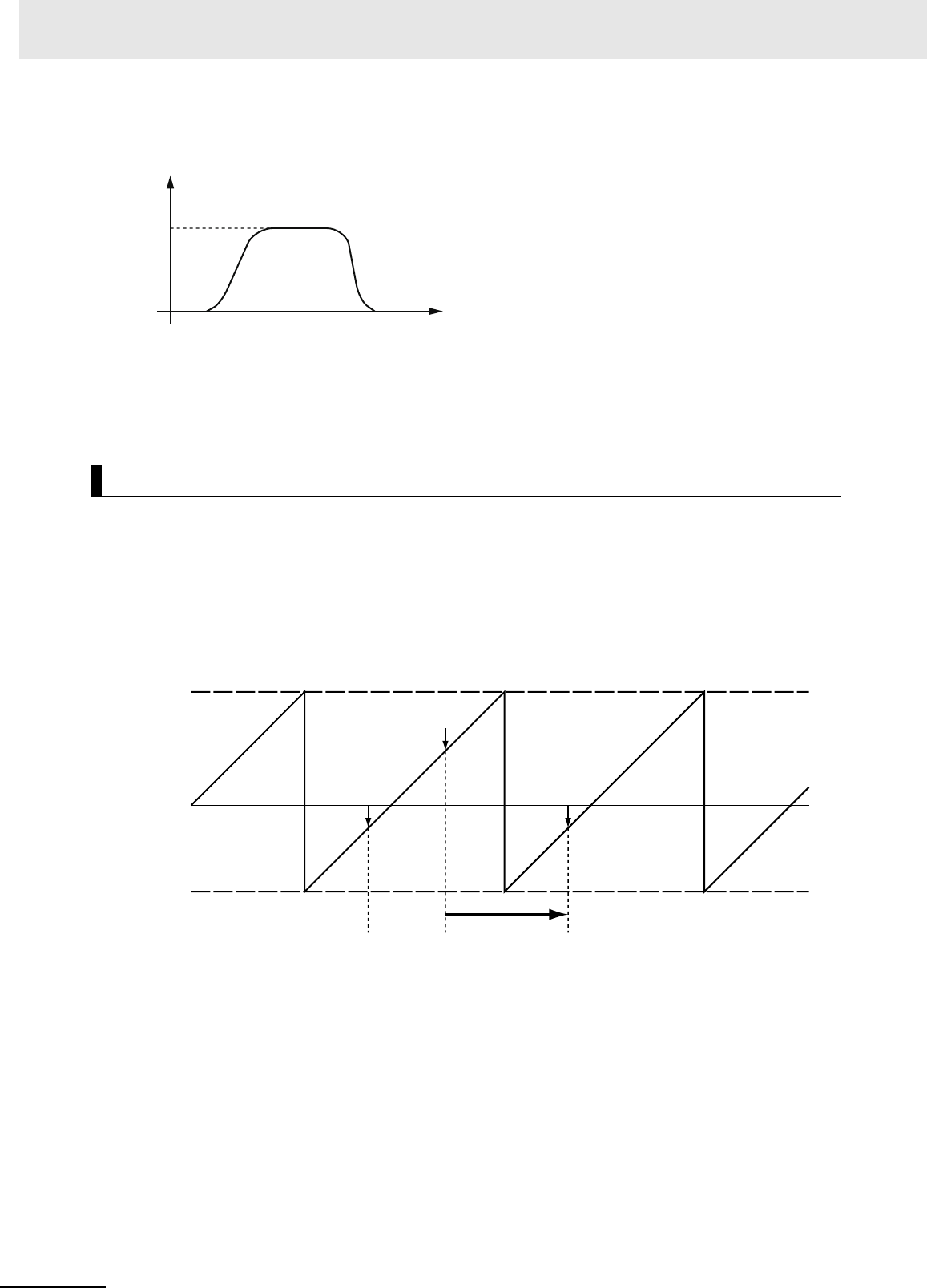
3 Axis Command Instructions
3-52
NJ/NX-series Motion Control Instructions Reference Manual (W508)
Specify Jerk when you want to accelerate or decelerate smoothly. The following chart shows an opera-
tion example when Jerk is specified.
For details on Jerk, refer to the NJ/NX-series CPU Unit Motion Control User’s Manual (Cat. No. W507)
or NY-series Industrial Panel PC / Industrial Box PC Motion Control User’s Manual (Cat. No. W559).
When the positioning is started with Position (Target Position) set to the command current position, the
axis will not move but Done will change to TRUE.
This section describes the instruction in detail.
Direction
Direction specifies the direction for starting positioning when the Count Mode is Rotary Mode. Direc-
tion is not used if the Count Mode is Linear Mode. Positioning starts in the positive direction towards
the target position when the positive direction is specified for Direction. The following chart shows an
operation example when positioning starts with a command position of 50 and moves toward −20.
Instruction Details
0
Time
Target position
Command current
position
Target
velocity
Velocity
Command current
position: 50
Moves in positive direction.
Target position:
−20
Target position:
−20
Modulo minimum
position setting
value: −70
Modulo maximum
position setting
value: 100
0

3-53
3 Axis Command Instructions
NJ/NX-series Motion Control Instructions Reference Manual (W508)
MC_MoveAbsolute
3
Function
Positioning starts in the negative direction towards the target position when the negative direction is
specified for Direction. The following chart shows an operation example when positioning starts with
a command position of 50 and moves toward −20.
Positioning starts towards the target position within the ring counter range when No direction is
specified for Direction. Therefore, the size relationship between the command current position and
the target position determines the direction of travel.
The following chart shows an operation example when positioning starts with a command position of
50 and moves toward −20.
0
Command current
position: 50
Moves in negative direction.
Target position:
−20
Target position:
−20
Modulo minimum
position setting
value: −70
Modulo maximum
position setting
value: 100
0
Command current
position: 50
Moves towards the ring
counter range.
Target position:
−20
Target position:
−20
Modulo minimum
position setting
value: −70
Modulo maximum
position setting
value: 100

3 Axis Command Instructions
3-54
NJ/NX-series Motion Control Instructions Reference Manual (W508)
When No direction is specified for Direction, you can specify a Position (Target Position) outside the
range specified by the modulo maximum position and modulo minimum position setting values.
When Position (Target Position) is outside the range specified by the modulo maximum position and
modulo minimum position setting values, positioning is performed using the travel distance exceed-
ing the modulo maximum position setting value as a relative distance. This allows positioning of mul-
tiple ring rotations. Positioning is the same when Position (Target Position) is below the modulo
minimum position setting value as well. The following chart shows an operation example for when
the command current position is −20 and Position (Target Position) is 290.
When the shortest way is specified for Direction, positioning starts in the direction with the shortest
distance between the command current position and the target position. The following chart shows
an operation example when positioning starts with a command position of 50 and moves toward
−20.
Movement is in the same direction as the current direction if the travel distance is the same in the
positive and the negative direction.
0
190
Performs relative positioning with the target distance as
(290 (Target position) − 100 (Upper limit)) = 190.
Position after
positioning: −50
Command
current position:
−20
Modulo minimum
position setting
value: −70
Modulo maximum
position setting
value: 100
0
Target position:
−20
Target position:
−20
Moves in the direction with
the shortest travel distance.
Command current
position: 50
Modulo minimum
position setting
value: −70
Modulo maximum
position setting
value: 100

3-55
3 Axis Command Instructions
NJ/NX-series Motion Control Instructions Reference Manual (W508)
MC_MoveAbsolute
3
Function
Precautions for Correct UsePrecautions for Correct Use
• When you perform absolute positioning, set the target position so that it is less than the Mod-
ulo Maximum Position Setting Value axis parameter and greater than or equal to the Modulo
Minimum Position Setting Value axis parameter. If the target position is greater than or equal to
the setting of the Modulo Maximum Position Setting Value axis parameter or less than the set-
ting of the Modulo Minimum Position Setting Value axis parameter, a Target Position Setting
Out of Range error (error code 5478 hex) will occur. However, when No direction is specified
for Direction, you can specify a Position (Target Position) outside the range specified by the
modulo maximum position and modulo minimum position setting values.
• If the current direction is specified for Direction, operation is in the same command direction as
the previous motion. Therefore, depending on the instructions that are used together, the
direction may not be the same as the direction that was specified with the input to the motion
control instruction for the previous motion. When you specify the current direction, check the
current direction with Dir.Posi (Positive Direction) and Dir.Nega (Negative Direction) in the Axis
Variable.
In-position Check
An in-position check is performed for this instruction according to the settings in In-position Range
and In-position Check Time axis parameters.

3 Axis Command Instructions
3-56
NJ/NX-series Motion Control Instructions Reference Manual (W508)
• Busy (Executing) changes to TRUE at the same time as Execute changes to TRUE. Active (Con-
trolling) changes to TRUE in the next period.
• Done changes to TRUE when Position (Target Position) is reached and positioning is completed.
• If another instruction aborts this instruction, CommandAborted changes to TRUE and Busy (Execut-
ing) and Active (Controlling) change to FALSE.
You can change the operation of the instruction if you change an input variable during positioning and
change Execute to TRUE again.
Input variables Position (Target Position), Velocity (Target Velocity), Acceleration (Acceleration Rate),
and Deceleration (Deceleration Rate) can be changed by re-executing the motion control instruction.
For details on re-execution of motion control instructions, refer to the NJ/NX-series CPU Unit Motion
Control User’s Manual (Cat. No. W507) or NY-series Industrial Panel PC / Industrial Box PC Motion
Control User’s Manual (Cat. No. W559).
For details on multi-execution of motion control instructions, refer to the NJ/NX-series CPU Unit Motion
Control User’s Manual (Cat. No. W507) or NY-series Industrial Panel PC / Industrial Box PC Motion
Control User’s Manual (Cat. No. W559).
Timing Charts
Re-execution of Motion Control Instructions
Multi-execution of Motion Control Instructions
Busy
Done
CommandAborted
Active
Error
16#0000
ErrorID
Execute
Velocity
Multi-execution of
another instruction
Time

3-57
3 Axis Command Instructions
NJ/NX-series Motion Control Instructions Reference Manual (W508)
MC_MoveAbsolute
3
Function
Execution during Execution of Other Instructions
You can switch to this instruction or buffer this instruction if you execute it during execution of
another instruction. You can buffer one instruction per axis. Specify the operation of this instruction
using BufferMode (Buffer Mode Selection) for multi-execution of instructions.
For details on BufferMode (Buffer Mode Selection), refer to the NJ/NX-series CPU Unit Motion Con-
trol User's Manual (Cat. No. W507) or NY-series Industrial Panel PC / Industrial Box PC Motion Con-
trol User’s Manual (Cat. No. W559).
Execution of Other Instructions during Instruction Execution
If you execute another instruction during execution of this instruction, you can specify aborting, buff-
ering, or blending.
Buffer Mode Selection Description
Aborting Aborts the instruction being executed and switches to this instruction.
If the direction of axis motion is reversed by switching instructions, the
motion will be reversed according to the Operation Selection at Reversing
axis parameter.
Buffered Buffers this instruction and executes it automatically after the current
instruction is completed.
Blending Starts the buffered instruction at the velocity (transit velocity) at which the
current instruction reaches the target position. The operation of the current
instruction is changed so that the axes reach the target position at the tran-
sit velocity. There are four methods to specify the transit velocity. These are
described below.
Blending low The lower of the target velocities of the current instruction and the buffered
instruction is used as the transit velocity.
Blending previous The target velocity of the current instruction is used as the transit velocity.
Blending next The target velocity of the buffered instruction is used as the transit velocity.
Blending high The higher of the target velocities of the current instruction and the buffered
instruction is used as the transit velocity.

3 Axis Command Instructions
3-58
NJ/NX-series Motion Control Instructions Reference Manual (W508)
If an error occurs during instruction execution, Error will change to TRUE and the axis will stop. You can
find out the cause of the error by referring to the value output by ErrorID (Error Code).
Timing Chart When Error Occurs
Error Codes
Refer to A-1 Error Codes for instruction errors.
Errors
Error code
Busy
Done
CommandAborted
Active
Error
16#0000
ErrorID
Execute

3-59
3 Axis Command Instructions
NJ/NX-series Motion Control Instructions Reference Manual (W508)
MC_MoveAbsolute
3
Sample Programming 1
This section shows sample programming for positioning by periodic multi-execution of instructions.
The minimum settings required for this sample programming are given below.
Setting Axis Parameters
Axis Type
Count Mode
Unit of Display
In this sample, BufferMode (Buffer Mode Selection) is set to Buffered for MC_MoveAbsolute (Absolute
Positioning) instructions and the axis is moved to the final target position by executing multiple instruc-
tions.
When the axis reaches the final target position, it is returned to home with the MC_ZeroPosition (High-
speed Home) instruction.
Multi-execution of instructions is performed when the Active (Controlling) output variable from the previ-
ous instruction is TRUE. For single-axis operation, multi-execution is possible for only one instruction.
Operation Pattern
Sample Programming 1
Parameter Settings
Axis Axis Type
Axis 1 Servo axis
Axis Count Mode
Axis 1 Linear Mode
Axis Unit of Display
Axis 1 mm
Operation Example
30.00
20.00
10.00
0
250.00
50.00 100.00 200.00
Axis 1 (mm)
(1)
(2)
(3)
(4)
Positive direction
Velocity (mm/s)
Operation started. Operation started. Operation started. Operation started.
Multi-execution of
instructions
High-speed Home instruction executed.
Multi-execution of
instructions
Multi-execution of
instructions

3 Axis Command Instructions
3-60
NJ/NX-series Motion Control Instructions Reference Manual (W508)
1
Turning ON the Operation Start Switch
When you turn ON the operation start switch at home, axis 1 is positioned to 50.00 mm in the
positive direction.
2
Turning ON the Operation Start Switch Again
Thereafter, axis 1 is positioned to 100.00 mm and 200.00 mm, and then returns to home and
stops. The operation start switch must be turned ON once for each of these motions.
Main Variables
Timing Chart
Ladder Diagram
Name Data type Default Comment
MC_Axis000 _sAXIS_REF --- Axis Variable for axis 1.
MC_Axis000.MFaultLvl.Active BOOL FALSE TRUE while there is a minor fault level error for
axis 1.
MC_Axis000.Details.Homed BOOL FALSE TRUE when home is defined for axis 1.
Pwr_Status BOOL FALSE This variable is assigned to the Status output
variable from the PWR instance of the MC_Power
instruction. This variable changes to TRUE when
the Servo is turned ON.
StartPg BOOL FALSE The Servo is turned ON if this variable is TRUE
and EtherCAT process data communications are
established.
Pwr_Status
Hm_D
Hm_Bsy
Mv_Abs1_D
Mv_Abs1_Bsy
Mv_Abs1_Act
Mv_Abs2_D
Mv_Abs2_Bsy
Mv_Abs2_Act
Mv_Abs3_D
Mv_Abs3_Bsy
Mv_Abs3_Act
Mv_Zero_D
Mv_Zero_Bsy
Mv_Zero_Act

3-61
3 Axis Command Instructions
NJ/NX-series Motion Control Instructions Reference Manual (W508)
MC_MoveAbsolute
3
Sample Programming 1
Sample Programming
Lock1
PWR
Error
Axis Axis
Enable Status
Busy
MC_Power
ErrorID
StartPg
MC_Axis000
Pwr_Status
Pwr_Bsy
Pwr_Err
Pwr_ErrID
HM
Axis Axis
Execute
Error
ErrorID
CommandAborted
MC_Home
Done
Busy
MC_Axis000
Pwr_Status
Hm_D
Hm_Bsy
Hm_Ca
Hm_Err
Hm_ErrID
BufferMode
MV_ABS1
Deceleration
Active
Axis Axis
Execute Done
Position Busy
Acceleration
Error
Jerk
Direction
MC_MoveAbsolute
Velocity
CommandAborted
ErrorID
MC_Axis000
Hm_D
_eMC_DIRECTION#_mcNoDirection
LREAL#50.0
LREAL#10.0
LREAL#1000.0
LREAL#1000.0
Mv_Abs1_Bsy
Mv_Abs1_Act
Mv_Abs1_Ca
Mv_Abs1_Err
Mv_Abs1_ErrID
Mv_Abs1_D
BufferMode
MV_ABS2
Deceleration
Active
Axis Axis
Execute Done
Position Busy
Acceleration
Error
Jerk
Direction
MC_MoveAbsolute
Velocity
CommandAborted
ErrorID
MC_Axis000
Mv_Abs1_Act
_eMC_DIRECTION#_mcNoDirection
_eMC_BUFFER_MODE#_mcBuffered
LREAL#100.0
LREAL#20.0
LREAL#1000.0
LREAL#1000.0
Mv_Abs2_Bsy
Mv_Abs2_Act
Mv_Abs2_Ca
Mv_Abs2_Err
Mv_Abs2_ErrID
Mv_Abs2_D
FaultHandlerMC_Axis000.MFaultLvl.Active
FaultHandlerEN
Lock1
MC_Axis000.DrvStatus.ServoReady
MC_Axis000.Details.Homed
If the Servo Drive is ready, the Servo is turned ON.
If the Servo is ON and home is not defined, the Home instruction is executed.
After home is defined, absolute positioning 1 is started.
After absolute positioning 1 is started, absolute positioning 2 is started with multi-execution of instructions.
If a minor fault level error occurs for axis 1, the error handler for the device (FaultHandler) is executed.
Program the FaultHandler according to the device.
If StartPg is TRUE, check that the Servo Drive is ready.

3 Axis Command Instructions
3-62
NJ/NX-series Motion Control Instructions Reference Manual (W508)
Main Variables
Structured Text (ST)
Name Data type Default Comment
MC_Axis000 _sAXIS_REF --- Axis Variable for axis 1.
MC_Axis000.MFaultLvl.Active BOOL FALSE TRUE while there is a minor fault level error for
axis 1.
MC_Axis000.Details.Homed BOOL FALSE TRUE when home is defined for axis 1.
Pwr_Status BOOL FALSE This variable is assigned to the Status output
variable from the PWR instance of the MC_Power
instruction. This variable changes to TRUE when
the Servo is turned ON.
StartPg BOOL FALSE The Servo is turned ON if this variable is TRUE
and EtherCAT process data communications are
established.
Hm_Ex BOOL FALSE The HM instance of MC_Home is executed when
this variable changes to TRUE.
Mv_Abs1_Ex BOOL FALSE The MV_ABS1 instance of MC_MoveAbsolute is
executed when this variable changes to TRUE.
Mv_Abs2_Ex BOOL FALSE The MV_ABS2 instance of MC_MoveAbsolute is
executed when this variable changes to TRUE.
Mv_Abs3_Ex BOOL FALSE The MV_ABS3 instance of MC_MoveAbsolute is
executed when this variable changes to TRUE.
Mv_Zero_Ex BOOL FALSE The MV_ZERO instance of MC_MoveZeroPosi-
tion is executed when this variable changes to
TRUE.
InitFlag BOOL FALSE This variable indicates if it is necessary to set the
input parameters. Input parameters are set when
this variable is FALSE. When setting the input
parameters is completed, this variable changes to
TRUE.
BufferMode
MV_ABS3
Deceleration
Active
Axis Axis
Execute Done
Position Busy
Acceleration
Error
Jerk
Direction
MC_MoveAbsolute
Velocity
CommandAborted
ErrorID
MC_Axis000
Mv_Abs2_Act
_eMC_DIRECTION#_mcNoDirection
_eMC_BUFFER_MODE#_mcBuffered
LREAL#200.0
LREAL#30.0
LREAL#1000.0
LREAL#1000.0
Mv_Abs3_Bsy
Mv_Abs3_Act
Mv_Abs3_Ca
Mv_Abs3_Err
Mv_Abs3_ErrID
Mv_Abs3_D
MC_Axis000
Mv_Abs3_Act
_eMC_BUFFER_MODE#_mcBuffered
LREAL#250.0
LREAL#1000.0
LREAL#1000.0
Mv_Zero_Bsy
Mv_Zero_Act
Mv_Zero_Ca
Mv_Zero_Err
Mv_Zero_ErrID
Mv_Zero_D
MV_ZERO
Jerk
Active
Axis Axis
Execute Done
Velocity Busy
Deceleration
Error
BufferMode
MC_MoveZeroPosition
Acceleration
CommandAborted
ErrorID
After absolute positioning 2 is started, absolute positioning 3 is started with multi-execution of instructions.
After absolute positioning 3 is started, the High-speed Home instruction is executed.

3-63
3 Axis Command Instructions
NJ/NX-series Motion Control Instructions Reference Manual (W508)
MC_MoveAbsolute
3
Sample Programming 1
Timing Chart
Sample Programming
// Processing when input parameters are not set
IF InitFlag = FALSE THEN
// MV_ABS1 parameters
Mv_Abs1_Pos := LREAL#50.0;
Mv_Abs1_Vel := LREAL#10.0;
Mv_Abs1_Acc := LREAL#1000.0;
Mv_Abs1_Dec := LREAL#1000.0;
Mv_Abs1_Dir := _eMC_DIRECTION#_mcNoDirection;
// MV_ABS2 parameters
Mv_Abs2_Pos := LREAL#100.0;
Mv_Abs2_Vel := LREAL#20.0;
Mv_Abs2_Acc := LREAL#1000.0;
Mv_Abs2_Dec := LREAL#1000.0;
Mv_Abs2_Dir := _eMC_DIRECTION#_mcNoDirection;
Mv_Abs2_Bm := _eMC_BUFFER_MODE#_mcBuffered;
// MV_ABS3 parameters
Mv_Abs3_Pos := LREAL#200.0;
Mv_Abs3_Vel := LREAL#30.0;
Mv_Abs3_Acc := LREAL#1000.0;
Mv_Abs3_Dec := LREAL#1000.0;
Mv_Abs3_Dir := _eMC_DIRECTION#_mcNoDirection;
Mv_Abs3_Bm := _eMC_BUFFER_MODE#_mcBuffered;
// MV_ZERO parameters
Mv_Zero_Vel := LREAL#250;
Mv_Zero_Acc := LREAL#1000.0;
Pwr_Status
Hm_Ex
Hm_D
Hm_Bsy
Mv_Abs1_Ex
Mv_Abs1_D
Mv_Abs1_Bsy
Mv_Abs1_Act
Mv_Abs2_Ex
Mv_Abs2_D
Mv_Abs2_Bsy
Mv_Abs2_Act
Mv_Abs3_D
Mv_Abs3_Ex
Mv_Abs3_Bsy
Mv_Abs3_Act
Mv_Zero_D
Mv_Zero_Ex
Mv_Zero_Bsy
Mv_Zero_Act

3 Axis Command Instructions
3-64
NJ/NX-series Motion Control Instructions Reference Manual (W508)
Mv_Zero_Dec := LREAL#1000.0;
Mv_Zero_Bm := _eMC_BUFFER_MODE#_mcBuffered;
// Change InitFlag to TRUE after setting the input parameters.
InitFlag:=TRUE;
END_IF;
// If StartPg is TRUE and the Servo Drive is ready, the Servo is turned ON.
// If the Servo Drive is not ready, the Servo is turned OFF.
IF (StartPg=TRUE)
AND (MC_Axis000.DrvStatus.Ready=TRUE) THEN
Pwr_En:=TRUE;
ELSE
Pwr_En:=FALSE;
END_IF;
// Processing for a minor fault level error
// Program the FaultHandler according to the device.
IF MC_Axis000.MFaultLvl.Active=TRUE THEN
FaultHandler();
END_IF;
// If the Servo is ON and home is not defined, the Home instruction is executed.
IF (Pwr_Status=TRUE) AND (MC_Axis000.Details.Homed=FALSE) THEN
Hm_Ex:=TRUE;
END_IF;
// After home is defined, MV_ABS1 is executed.
IF Hm_D=TRUE THEN
Mv_Abs1_Ex:=TRUE;
END_IF;
// After MV_ABS1 is started, MV_ABS2 is executed with multi-execution of instructions.
IF Mv_Abs1_Act=TRUE THEN
Mv_Abs2_Ex:=TRUE;
END_IF;
// After MV_ABS2 is started, MV_ABS3 is executed with multi-execution of instructions.
IF Mv_Abs2_Act=TRUE THEN
Mv_Abs3_Ex:=TRUE;
END_IF;
// After MV_ABS3 is started, MV_ZERO is executed with multi-execution of instructions.
IF Mv_Abs3_Act=TRUE THEN
Mv_Zero_Ex:=TRUE;
END_IF;

3-65
3 Axis Command Instructions
NJ/NX-series Motion Control Instructions Reference Manual (W508)
MC_MoveAbsolute
3
Sample Programming 1
//MC_Power
PWR(
Axis := MC_Axis000,
Enable := Pwr_En,
Status => Pwr_Status,
Busy => Pwr_Bsy,
Error => Pwr_Err,
ErrorID => Pwr_ErrID
);
//MC_Home
HM(
Axis := MC_Axis000,
Execute := Hm_Ex,
Done => Hm_D,
Busy => Hm_Bsy,
CommandAborted => Hm_Ca,
Error => Hm_Err,
ErrorID => Hm_ErrID
);
//MC_MoveAbsolute
MV_ABS1(
Axis := MC_Axis000,
Execute := Mv_Abs1_Ex,
Position := Mv_Abs1_Pos,
Velocity := Mv_Abs1_Vel,
Acceleration := Mv_Abs1_Acc,
Deceleration := Mv_Abs1_Dec,
Direction := Mv_Abs1_Dir,
Done => Mv_Abs1_D,
Busy => Mv_Abs1_Bsy,
Active => Mv_Abs1_Act,
CommandAborted => Mv_Abs1_Ca,
Error => Mv_Abs1_Err,
ErrorID => Mv_Abs1_ErrID
);
MV_ABS2(
Axis := MC_Axis000,
Execute := Mv_Abs2_Ex,
Position := Mv_Abs2_Pos,
Velocity := Mv_Abs2_Vel,
Acceleration := Mv_Abs2_Acc,
Deceleration := Mv_Abs2_Dec,
Direction := Mv_Abs2_Dir,
BufferMode := Mv_Abs2_Bm,
Done => Mv_Abs2_D,
Busy => Mv_Abs2_Bsy,
Active => Mv_Abs2_Act,
CommandAborted => Mv_Abs2_Ca,
Error => Mv_Abs2_Err,
ErrorID => Mv_Abs2_ErrID
);
MV_ABS3(
Axis := MC_Axis000,
Execute := Mv_Abs3_Ex,
Position := Mv_Abs3_Pos,
Velocity := Mv_Abs3_Vel,
Acceleration := Mv_Abs3_Acc,

3 Axis Command Instructions
3-66
NJ/NX-series Motion Control Instructions Reference Manual (W508)
Deceleration := Mv_Abs3_Dec,
Direction := Mv_Abs3_Dir,
BufferMode := Mv_Abs3_Bm,
Done => Mv_Abs3_D,
Busy => Mv_Abs3_Bsy,
Active => Mv_Abs3_Act,
CommandAborted => Mv_Abs3_Ca,
Error => Mv_Abs3_Err,
ErrorID => Mv_Abs3_ErrID
);
//MC_MoveZeroPosition
MV_ZERO(
Axis := MC_Axis000,
Execute := Mv_Zero_Ex,
Velocity := Mv_Zero_Vel,
Acceleration := Mv_Zero_Acc,
Deceleration := Mv_Zero_Dec,
BufferMode := Mv_Zero_Bm,
Done => Mv_Zero_D,
Busy => Mv_Zero_Bsy,
Active => Mv_Zero_Act,
CommandAborted => Mv_Zero_Ca,
Error => Mv_Zero_Err,
ErrorID => Mv_Zero_ErrID
);

3-67
3 Axis Command Instructions
NJ/NX-series Motion Control Instructions Reference Manual (W508)
MC_MoveAbsolute
3
Sample Programming 2
In this sample, when the Count Mode is set to Rotary Mode and positioning is performed toward the tar-
get position, the shortest direction, clockwise or counterclockwise, is automatically determined and
positioning is performed.
This section shows sample programming for shortest-way control of the rotation direction of a tool
changer.
The minimum settings required for this sample programming are given below.
Setting Axis Parameters
Axis Type
Count Mode
Ring Counter
Unit of Display
In this sample, multi-execution of absolute positioning instructions is used to position in a range of 0° to
360°. The actual position returns to 0° once it exceeds the range of 0° to 360°.
Multi-execution of instructions is performed when the Active (Controlling) output variable from the previ-
ous instruction is TRUE. For single-axis operation, multi-execution is possible for only one instruction.
In this sample, multi-execution of instructions is executed with BufferMode (Buffer Mode Selection) set
to Buffered.
Sample Programming 2
Parameter Settings
Axis Axis Type
Axis 1 Servo axis
Axis Count Mode
Axis 1 Rotary Mode
Axis
Modulo maximum
position
Modulo minimum
position
Axis 1 360 0
Axis Unit of Display
Axis 1 degree
Operation Example
Shortest-way positioning is performed.
0°
360°
90°
120°
180°
290°
300°

3 Axis Command Instructions
3-68
NJ/NX-series Motion Control Instructions Reference Manual (W508)
If you specify 0° (home), 90°, 120°, or 290°, the axis will move to that position. The rotation direction
in this instance is in the shorter rotation direction. The travel velocity is 250°/s.
The sample programming performs positioning with a shortest way specification from 290° to 90° to
120° and then to home (0°).
Main Variables
Timing Chart
Ladder Diagram
Name Data type Default Comment
MC_Axis000 _sAXIS_REF --- Axis Variable for axis 1.
MC_Axis000.MFaultLvl.Active BOOL FALSE TRUE while there is a minor fault level error for
axis 1.
MC_Axis000.Details.Homed BOOL FALSE TRUE when home is defined for axis 1.
Pwr_Status BOOL FALSE This variable is assigned to the Status output
variable from the PWR instance of the MC_Power
instruction. This variable changes to TRUE when
the Servo is turned ON.
StartPg BOOL FALSE The Servo is turned ON if this variable is TRUE
and EtherCAT process data communications are
established.
Pwr_Status
Hm_D
Hm_Bsy
Mv_Abs1_D
Mv_Abs1_Bsy
Mv_Abs1_Act
Mv_Abs2_D
Mv_Abs2_Bsy
Mv_Abs2_Act
Mv_Abs3_D
Mv_Abs3_Bsy
Mv_Abs3_Act
Mv_Abs4_D
Mv_Abs4_Bsy
Mv_Abs4_Act
MC_Axis000
Command velocity
Time

3-69
3 Axis Command Instructions
NJ/NX-series Motion Control Instructions Reference Manual (W508)
MC_MoveAbsolute
3
Sample Programming 2
Sample Programming
PWR
Error
Axis Axis
Enable Status
Busy
MC_Power
ErrorID
Lock1
MC_Axis000
Pwr_Status
Pwr_Bsy
Pwr_Err
Pwr_ErrID
FaultHandlerMC_Axis000.MFaultLvl.Active
FaultHandlerEN
StartPg
Lock1
MC_Axis000.DrvStatus.Ready
If the Servo Drive is ready, the Servo is turned ON.
If a minor fault level error occurs for axis 1, the error handler for the device (FaultHandler) is executed.
Program the FaultHandler according to the device.
If StartPg is TRUE, check that the Servo Drive is ready.

3 Axis Command Instructions
3-70
NJ/NX-series Motion Control Instructions Reference Manual (W508)
HM
Axis Axis
Execute
Error
ErrorID
CommandAborted
MC_Home
Done
Busy
MC_Axis000
Pwr_Status
Hm_D
Hm_Bsy
Hm_Ca
Hm_Err
Hm_ErrID
BufferMode
MV_ABS1
Deceleration
Active
Axis Axis
Execute Done
Position Busy
Acceleration
Error
Jerk
Direction
MC_MoveAbsolute
Velocity
CommandAborted
ErrorID
MC_Axis000
Hm_D
_eMC_DIRECTION#_mcShortestWay
LREAL#290.0
LREAL#250.0
LREAL#1000.0
LREAL#1000.0
Mv_Abs1_Bsy
Mv_Abs1_Act
Mv_Abs1_Ca
Mv_Abs1_Err
Mv_Abs1_ErrID
Mv_Abs1_D
BufferMode
MV_ABS2
Deceleration
Active
Axis Axis
Execute Done
Position Busy
Acceleration
Error
Jerk
Direction
MC_MoveAbsolute
Velocity
CommandAborted
ErrorID
MC_Axis000
Mv_Abs1_Act
_eMC_DIRECTION#_mcShortestWay
_eMC_BUFFER_MODE#_mcBuffered
LREAL#90.0
LREAL#250.0
LREAL#1000.0
LREAL#1000.0
Mv_Abs2_Bsy
Mv_Abs2_Act
Mv_Abs2_Ca
Mv_Abs2_Err
Mv_Abs2_ErrID
Mv_Abs2_D
MC_Axis000.Details.Homed
BufferMode
MV_ABS3
Deceleration
Active
Axis Axis
Execute Done
Position Busy
Acceleration
Error
Jerk
Direction
MC_MoveAbsolute
Velocity
CommandAborted
ErrorID
MC_Axis000
Mv_Abs2_Act
_eMC_DIRECTION#_mcShortestWay
_eMC_BUFFER_MODE#_mcBuffered
LREAL#120.0
LREAL#250.0
LREAL#1000.0
LREAL#1000.0
Mv_Abs3_Bsy
Mv_Abs3_Act
Mv_Abs3_Ca
Mv_Abs3_Err
Mv_Abs3_ErrID
Mv_Abs3_D
If the Servo is ON and home is not defined, the Home instruction is executed.
After home is defined, absolute positioning 1 is executed to move to 290.0°.
The shortest way is specified for the motion direction.
Absolute positioning 2 is executed with multi-execution of instructions to move from 290.0° to 90.0°.
The shortest way is used for the motion direction.
Absolute positioning 3 is executed with multi-execution of instructions to move from 90.0° to 120.0°.
The shortest way is used for the motion direction.

3-71
3 Axis Command Instructions
NJ/NX-series Motion Control Instructions Reference Manual (W508)
MC_MoveAbsolute
3
Sample Programming 2
Main Variables
Structured Text (ST)
Name Data type Default Comment
MC_Axis000 _sAXIS_REF --- Axis Variable for axis 1.
MC_Axis000.MFaultLvl.Active BOOL FALSE TRUE while there is a minor fault level error for
axis 1.
MC_Axis000.Details.Homed BOOL FALSE TRUE when home is defined for axis 1.
Pwr_Status BOOL FALSE This variable is assigned to the Status output
variable from the PWR instance of the MC_Power
instruction. This variable changes to TRUE when
the Servo is turned ON.
StartPg BOOL FALSE The Servo is turned ON if this variable is TRUE
and EtherCAT process data communications are
established.
Hm_Ex BOOL FALSE The HM instance of MC_Home is executed when
this variable changes to TRUE.
Mv_Abs1_Ex BOOL FALSE The MV_ABS1 instance of MC_MoveAbsolute is
executed when this variable changes to TRUE.
Mv_Abs2_Ex BOOL FALSE The MV_ABS2 instance of MC_MoveAbsolute is
executed when this variable changes to TRUE.
Mv_Abs3_Ex BOOL FALSE The MV_ABS3 instance of MC_MoveAbsolute is
executed when this variable changes to TRUE.
Mv_Abs4_Ex BOOL FALSE The MV_ABS4 instance of MC_MoveAbsolute is
executed when this variable changes to TRUE.
InitFlag BOOL FALSE This variable indicates if it is necessary to set the
input parameters. Input parameters are set when
this variable is FALSE. When setting the input
parameters is completed, this variable changes to
TRUE.
BufferMode
MV_ABS4
Deceleration
Active
Axis Axis
Execute Done
Position Busy
Acceleration
Error
Jerk
Direction
MC_MoveAbsolute
Velocity
CommandAborted
ErrorID
MC_Axis000
Mv_Abs3_Act
_eMC_DIRECTION#_mcShortestWay
_eMC_BUFFER_MODE#_mcBuffered
LREAL#0.0
LREAL#250.0
LREAL#1000.0
LREAL#1000.0
Mv_Abs4_Bsy
Mv_Abs4_Act
Mv_Abs4_Ca
Mv_Abs4_Err
Mv_Abs4_ErrID
Mv_Abs4_D
Absolute positioning 4 is executed with multi-execution of instructions to move from 120.0° to 0.0°.
The shortest way is used for the motion direction.

3 Axis Command Instructions
3-72
NJ/NX-series Motion Control Instructions Reference Manual (W508)
Timing Chart
Sample Programming
// Processing when input parameters are not set
IF InitFlag = FALSE THEN
// MV_ABS1 parameters
Mv_Abs1_Pos := LREAL#290.0;
Mv_Abs1_Vel := LREAL#250.0;
Mv_Abs1_Acc := LREAL#1000.0;
Mv_Abs1_Dec := LREAL#1000.0;
Mv_Abs1_Dir := _eMC_DIRECTION#_mcShortestWay;
// MV_ABS2 parameters
Mv_Abs2_Pos := LREAL#90.0;
Mv_Abs2_Vel := LREAL#250.0;
Mv_Abs2_Acc := LREAL#1000.0;
Mv_Abs2_Dec := LREAL#1000.0;
Mv_Abs2_Dir := _eMC_DIRECTION#_mcShortestWay;
Mv_Abs2_Bm := _eMC_BUFFER_MODE#_mcBuffered;
// MV_ABS3 parameters
Pwr_Status
Hm_Ex
Hm_D
Hm_Bsy
Mv_Abs1_Ex
Mv_Abs1_D
Mv_Abs1_Bsy
Mv_Abs1_Act
Mv_Abs2_Ex
Mv_Abs2_D
Mv_Abs2_Bsy
Mv_Abs2_Act
Mv_Abs3_Ex
Mv_Abs3_D
Mv_Abs3_Bsy
Mv_Abs3_Act
Mv_Abs4_Ex
Mv_Abs4_D
Mv_Abs4_Bsy
Mv_Abs4_Act
MC_Axis000
Command velocity
Time

3-73
3 Axis Command Instructions
NJ/NX-series Motion Control Instructions Reference Manual (W508)
MC_MoveAbsolute
3
Sample Programming 2
Mv_Abs3_Pos := LREAL#120.0;
Mv_Abs3_Vel := LREAL#250.0;
Mv_Abs3_Acc := LREAL#1000.0;
Mv_Abs3_Dec := LREAL#1000.0;
Mv_Abs3_Dir := _eMC_DIRECTION#_mcShortestWay;
Mv_Abs3_Bm := _eMC_BUFFER_MODE#_mcBuffered;
// MV_ABS4 parameters
Mv_Abs4_Pos := LREAL#0.0;
Mv_Abs4_Vel := LREAL#250.0;
Mv_Abs4_Acc := LREAL#1000.0;
Mv_Abs4_Dec := LREAL#1000.0;
Mv_Abs4_Dir := _eMC_DIRECTION#_mcShortestWay;
Mv_Abs4_Bm := _eMC_BUFFER_MODE#_mcBuffered;
// Change InitFlag to TRUE after setting the input parameters.
InitFlag := TRUE;
END_IF;
// If StartPg is TRUE and the Servo Drive is ready, the Servo is turned ON.
// If the Servo Drive is not ready, the Servo is turned OFF.
IF (StartPg=TRUE)
AND (MC_Axis000.DrvStatus.Ready=TRUE) THEN
Pwr_En:=TRUE;
ELSE
Pwr_En:=FALSE;
END_IF;
// Processing for a minor fault level error
// Program the FaultHandler according to the device.
IF MC_Axis000.MFaultLvl.Active=TRUE THEN
FaultHandler();
END_IF;
// If the Servo is ON and home is not defined, the Home instruction is executed.
IF (Pwr_Status=TRUE) AND (MC_Axis000.Details.Homed=FALSE) THEN
Hm_Ex:=TRUE;
END_IF;
// After home is defined, MV_ABS1 is executed.
IF Hm_D=TRUE THEN
Mv_Abs1_Ex:=TRUE;
END_IF;
// After MV_ABS1 is started, MV_ABS2 is executed with multi-execution of instructions.
IF Mv_Abs1_Act=TRUE THEN
Mv_Abs2_Ex:=TRUE;
END_IF;
// After MV_ABS2 is started, MV_ABS3 is executed with multi-execution of instructions.
IF Mv_Abs2_Act=TRUE THEN
Mv_Abs3_Ex:=TRUE;
END_IF;
// After MV_ABS3 is started, MV_ABS4 is executed with multi-execution of instructions.
IF Mv_Abs3_Act=TRUE THEN
Mv_Abs4_Ex:=TRUE;
END_IF;
// MC_Power
PWR(
Axis := MC_Axis000,
Enable := Pwr_En,

3 Axis Command Instructions
3-74
NJ/NX-series Motion Control Instructions Reference Manual (W508)
Status => Pwr_Status,
Busy => Pwr_Bsy,
Error => Pwr_Err,
ErrorID => Pwr_ErrID
);
// MC_Home
HM(
Axis := MC_Axis000,
Execute := Hm_Ex,
Done => Hm_D,
Busy => Hm_Bsy,
CommandAborted => Hm_Ca,
Error => Hm_Err,
ErrorID => Hm_ErrID
);
// Absolute positioning (1)
MV_ABS1(
Axis := MC_Axis000,
Execute := Mv_Abs1_Ex,
Position := Mv_Abs1_Pos,
Velocity := Mv_Abs1_Vel,
Acceleration := Mv_Abs1_Acc,
Deceleration := Mv_Abs1_Dec,
Direction := Mv_Abs1_Dir,
Done => Mv_Abs1_D,
Busy => Mv_Abs1_Bsy,
Active => Mv_Abs1_Act,
CommandAborted => Mv_Abs1_Ca,
Error => Mv_Abs1_Err,
ErrorID => Mv_Abs1_ErrID
);
// Absolute positioning (2)
MV_ABS2(
Axis := MC_Axis000,
Execute := Mv_Abs2_Ex,
Position := Mv_Abs2_Pos,
Velocity := Mv_Abs2_Vel,
Acceleration := Mv_Abs2_Acc,
Deceleration := Mv_Abs2_Dec,
Direction := Mv_Abs2_Dir,
BufferMode := Mv_Abs2_Bm,
Done => Mv_Abs2_D,
Busy => Mv_Abs2_Bsy,
Active => Mv_Abs2_Act,
CommandAborted => Mv_Abs2_Ca,
Error => Mv_Abs2_Err,
ErrorID => Mv_Abs2_ErrID
);
// Absolute positioning (3)
MV_ABS3(
Axis := MC_Axis000,
Execute := Mv_Abs3_Ex,
Position := Mv_Abs3_Pos,
Velocity := Mv_Abs3_Vel,
Acceleration := Mv_Abs3_Acc,
Deceleration := Mv_Abs3_Dec,
Direction := Mv_Abs3_Dir,
BufferMode := Mv_Abs3_Bm,
Done => Mv_Abs3_D,

3-75
3 Axis Command Instructions
NJ/NX-series Motion Control Instructions Reference Manual (W508)
MC_MoveAbsolute
3
Sample Programming 2
Busy => Mv_Abs3_Bsy,
Active => Mv_Abs3_Act,
CommandAborted => Mv_Abs3_Ca,
Error => Mv_Abs3_Err,
ErrorID => Mv_Abs3_ErrID
);
// Absolute positioning (4)
MV_ABS4(
Axis := MC_Axis000,
Execute := Mv_Abs4_Ex,
Position := Mv_Abs4_Pos,
Velocity := Mv_Abs4_Vel,
Acceleration := Mv_Abs4_Acc,
Deceleration := Mv_Abs4_Dec,
Direction := Mv_Abs4_Dir,
BufferMode := Mv_Abs4_Bm,
Done => Mv_Abs4_D,
Busy => Mv_Abs4_Bsy,
Active => Mv_Abs4_Act,
CommandAborted => Mv_Abs4_Ca,
Error => Mv_Abs4_Err,
ErrorID => Mv_Abs4_ErrID
);

3 Axis Command Instructions
3-76
NJ/NX-series Motion Control Instructions Reference Manual (W508)
MC_MoveRelative
The MC_MoveRelative instruction moves the axis the specified travel distance from the command cur-
rent position.
Instruction Name
FB/
FUN
Graphic expression ST expression
MC_MoveRelative Relative
Positioning
FB MC_MoveRelative_instance (
Axis :=parameter,
Execute :=parameter,
Distance :=parameter,
Velocity :=parameter,
Acceleration :=parameter,
Deceleration :=parameter,
Jerk :=parameter,
BufferMode :=parameter,
Done =>parameter,
Busy =>parameter,
Active =>parameter,
CommandAborted
=>parameter,
Error =>parameter,
ErrorID =>parameter
);
Variables
Input Variables
Name Meaning Data type Valid range Default Description
Execute Execute BOOL TRUE or FALSE FALSE The instruction is executed
when Execute changes to
TRUE.
Distance Travel
Distance
LREAL Negative number, posi-
tive number, or 0
0 Specify the travel distance
from the command current
position. The unit is command
units.
*1
Velocity Target
Velocity
LREAL Positive number 0
Specify the target velocity.
*2
The unit is command
units/s.
*1
Acceleration Acceleration
Rate
LREAL Non-negative number 0 Specify the acceleration rate.
The unit is command
units/s
2
.
*1
Deceleration Deceleration
Rate
LREAL Non-negative number 0 Specify the deceleration rate.
The unit is command
units/s
2
.
*1
Jerk Jerk LREAL Non-negative number 0 Specify the jerk. The unit is
command units/s
3
.
*1
MC_MoveRelative_instance
Deceleration
Active
Axis Axis
Execute Done
Distance Busy
Acceleration
Error
Jerk
BufferMode
MC_MoveRelative
Velocity
CommandAborted
ErrorID

3-77
3 Axis Command Instructions
NJ/NX-series Motion Control Instructions Reference Manual (W508)
MC_MoveRelative
3
Variables
*1 Refer to Unit Conversion Settings in the NJ/NX-series CPU Unit Motion Control User's Manual (Cat. No. W507) or NY-
series Industrial Panel PC / Industrial Box PC Motion Control User’s Manual (Cat. No. W559) for information on command
units.
*2 Always set the target velocity. If the axis is moved without setting a target velocity, an error will occur.
*3 The default value for an enumeration variable is actually not the number, but the enumerator.
*Refer to A-1 Error Codes.
Output Variable Update Timing
BufferMode Buffer Mode
Selection
_eMC_BUFFER_
MODE
0: _mcAborting
1: _mcBuffered
2: _mcBlendingLow
3: _mcBlendingPrevious
4: _mcBlendingNext
5: _mcBlendingHigh
0
*3
Specify the behavior when
executing more than one
motion instruction.
0: Aborting
1: Buffered
2: Blending low
3: Blending previous
4: Blending next
5: Blending high
Output Variables
Name Meaning Data type Valid range Description
Done Done BOOL TRUE or FALSE TRUE when the instruction is completed.
Busy Executing BOOL TRUE or FALSE TRUE when the instruction is acknowledged.
Active Controlling BOOL TRUE or FALSE TRUE when the axis is being controlled.
CommandAborted Command
Aborted
BOOL TRUE or FALSE TRUE when the instruction is aborted.
Error Error BOOL TRUE or FALSE TRUE while there is an error.
ErrorID Error Code WORD
*
Contains the error code when an error occurs.
A value of 16#0000 indicates normal execution.
Name Timing for changing to TRUE Timing for changing to FALSE
Done When positioning is completed. • When Execute is TRUE and changes to
FALSE.
• After one period when Execute is FALSE.
Busy When Execute changes to TRUE. • When Done changes to TRUE.
• When Error changes to TRUE.
• When CommandAborted changes to TRUE.
Active When the instruction is started. • When Done changes to TRUE.
• When Error changes to TRUE.
• When CommandAborted changes to TRUE.
CommandAborted • When this instruction is aborted because
another motion control instruction was exe-
cuted with the Buffer Mode set to Aborting.
• When this instruction is canceled due to an
error.
• When this instruction is executed while there is
an error.
• When you start this instruction during MC_Stop
instruction execution.
• When Execute is TRUE and changes to
FALSE.
• After one period when Execute is FALSE.
Error When there is an error in the execution conditions
or input parameters for the instruction.
When the error is cleared.
Name Meaning Data type Valid range Default Description

3 Axis Command Instructions
3-78
NJ/NX-series Motion Control Instructions Reference Manual (W508)
* Specify a user-defined Axis Variable that was created in the Axis Basic Settings of the Sysmac Studio (default: MC_Axis***)
or a system-defined axis variable name (_MC_AX[*], _MC1_AX[*], or _MC2_AX[*]).
• The travel distance from the command current position is specified to perform positioning.
• Relative positioning starts when Execute changes to TRUE.
• You can specify the Velocity (Target Velocity), Acceleration (Acceleration Rate), Deceleration (Decel-
eration Rate), and Jerk as input variables.
The following chart shows an operation example of relative positioning.
When the acceleration rate or deceleration rate is 0 and the instruction is executed, it will reach the tar-
get velocity without accelerating or decelerating.
The following chart shows an operation example of when the acceleration rate is 0.
Specify Jerk when you want to accelerate or decelerate smoothly. The following chart shows an opera-
tion example when Jerk is specified.
In-Out Variables
Name Meaning Data type Valid Ranges Description
Axis Axis _sAXIS_REF ---
Specify the axis.
*
Function
0
Velocity
Time
Travel distance
Command current position
Deceleration
Acceleration
Target
velocity
0
Time
Travel distance
Command current position
Acceleration
Target
velocity
Velocity
0
Time
Travel distance
Command current position
Target
velocity
Velocity

3-79
3 Axis Command Instructions
NJ/NX-series Motion Control Instructions Reference Manual (W508)
MC_MoveRelative
3
Function
For details on Jerk, refer to the NJ/NX-series CPU Unit Motion Control User’s Manual (Cat. No. W507)
or NY-series Industrial Panel PC / Industrial Box PC Motion Control User’s Manual (Cat. No. W559).
When the Count Mode is Rotary Mode, you can specify a Distance (Travel Distance) that exceeds the
relative distance range from the Modulo Minimum Position Setting Value axis parameter to the Modulo
Maximum Position Setting Value axis parameter so that you can perform multiple ring rotation position-
ing. The following chart shows an operation example when the command current position is −20 and
Distance (Travel Distance) is 300.
When Distance (Travel Distance) is 0 and the instruction is executed, the axis will not move, but Done
will change to TRUE.
Precautions for Correct UsePrecautions for Correct Use
Observe the following precautions if you re-execute relative positioning just before the comple-
tion of positioning. If positioning is completed before the MC Function Module re-executes the
instruction, normal instruction execution is performed.
• For normal instruction execution, positioning is performed to the relative value that is based on
the position of the axis when the instruction is executed.
• For re-execution of an instruction, positioning is performed to the relative value that is based
on the position of the axis when original instruction was executed.
In-position Check
An in-position check is performed for this instruction according to the settings in In-position Range
and In-position Check Time axis parameters.
Instruction Details
0
Position after
positioning: −60
Performs relative positioning with travel distance of 300.
300
Modulo maximum
position setting
value: 100
Modulo minimum
position setting
value: −70
Command
current
position: −20
elocity
Time
Instruction re-executed.
Velocity
Time
Instruction re-executed.
Relative position specified
for re-execution of instruction
Normal Instruction Execution Re-execution of Instruction
First position
of original
instruction
First position
of original
instruction
Relative position
specified for
original instruction
Relative position
specified for
instruction

3 Axis Command Instructions
3-80
NJ/NX-series Motion Control Instructions Reference Manual (W508)
• Busy (Executing) changes to TRUE at the same time as Execute changes to TRUE. Active (Con-
trolling) changes to TRUE in the next period.
• Done changes to TRUE when Distance (Target Distance) is reached and positioning is completed.
• If another instruction aborts this instruction, CommandAborted changes to TRUE and Busy (Execut-
ing) and Active (Controlling) change to FALSE.
You can change the operation of the instruction if you change an input variable during positioning and
change Execute to TRUE again.
Input variables Distance (Travel Distance), Velocity (Target Velocity), Acceleration (Acceleration Rate),
and Deceleration (Deceleration Rate) can be changed by re-executing the motion control instruction.
The starting point for Distance (Travel Distance) when the instruction is re-executed is not the command
current position for the first execution, but rather it is the command current position when the instruction
was first executed. The following chart shows an operation example when a motion control instruction is
re-executed twice with different values for Distance (Travel Distance) and Velocity (Target Velocity).
Timing Charts
Re-execution of Motion Control Instructions
Busy
Done
CommandAborted
Active
Error
16#0000
ErrorID
Execute
Time
Multi-execution of
instructions
Velocity
0
Third travel
distance
Second travel
distance
First travel
distance
Command current position
Time
Instruction re-executed.
Velocity
Instruction re-executed.

3-81
3 Axis Command Instructions
NJ/NX-series Motion Control Instructions Reference Manual (W508)
MC_MoveRelative
3
Function
Precautions for Correct UsePrecautions for Correct Use
To change any input parameter other than Distance (Travel Distance), re-execute the instruction
with Distance (Travel Distance) assigned to the same value as the original instruction.
For example, if Distance (Travel Distance) is changed to 0 when the instruction is re-executed,
the re-executed instruction will use a Distance (Travel Distance) of 0 from the first time it is exe-
cuted. This will cause the axis to return to the original first position, as shown below.
For details on re-execution of motion control instructions, refer to the NJ/NX-series CPU Unit Motion
Control User’s Manual (Cat. No. W507) or NY-series Industrial Panel PC / Industrial Box PC Motion
Control User’s Manual (Cat. No. W559).
For details on multi-execution of motion control instructions, refer to the NJ/NX-series CPU Unit Motion
Control User’s Manual (Cat. No. W507) or NY-series Industrial Panel PC / Industrial Box PC Motion
Control User’s Manual (Cat. No. W559).
Execution during Execution of Other Instructions
You can switch to this instruction or buffer this instruction if you execute it during execution of
another instruction. You can buffer one instruction per axis.
The starting point for Distance (Travel Distance) for multi-execution of the motion instruction is the
command current position when Active (Controlling) changes to TRUE after the start of instruction
execution.
Specify the operation of this instruction using BufferMode (Buffer Mode Selection) for multi-execu-
tion of instructions.
Multi-execution of Motion Control Instructions
Buffer Mode Selection Description
Aborting Aborts the instruction being executed and switches to this instruction.
If the direction of axis motion is reversed by switching instructions, the
motion will be reversed according to the Operation Selection at Reversing
axis parameter.
Buffered Buffers this instruction and executes it automatically after the current
instruction is completed.
Blending Starts the buffered instruction at the velocity (transit velocity) at which the
current instruction reaches the target position. The operation of the current
instruction is changed so that the axes reach the target position at the tran-
sit velocity. There are four methods to specify the transit velocity. These are
described below.
Blending low The lower of the target velocities of the current instruction and the buffered
instruction is used as the transit velocity.
Blending previous The target velocity of the current instruction is used as the transit velocity.
Blending next The target velocity of the buffered instruction is used as the transit velocity.
Blending high The higher of the target velocities of the current instruction and the buffered
instruction is used as the transit velocity.
elocity
Time
Instruction re-executed.
Target pos
Changed target velocity
First position
of original
instruction

3 Axis Command Instructions
3-82
NJ/NX-series Motion Control Instructions Reference Manual (W508)
For details on BufferMode (Buffer Mode Selection), refer to the NJ/NX-series CPU Unit Motion Con-
trol User's Manual (Cat. No. W507) or NY-series Industrial Panel PC / Industrial Box PC Motion Con-
trol User’s Manual (Cat. No. W559).
Execution of Other Instructions during Instruction Execution
If you execute another instruction during execution of this instruction, you can specify aborting, buff-
ering, or blending.
If an error occurs during instruction execution, Error will change to TRUE and the axis will stop. You can
find out the cause of the error by referring to the value output by ErrorID (Error Code).
Timing Chart When Error Occurs
Error code
Refer to A-1 Error Codes for instruction errors.
Errors
Error code
Busy
Done
CommandAborted
Active
Error
16#0000
ErrorID
Execute

3-83
3 Axis Command Instructions
NJ/NX-series Motion Control Instructions Reference Manual (W508)
MC_MoveVelocity
3
Variables
MC_MoveVelocity
The MC_MoveVelocity instruction performs velocity control with the Position Control Mode of the Servo
Drive.
Instruction Name FB/FUN Graphic expression ST expression
MC_MoveVelocity Velocity
Control
FB MC_MoveVelocity_instance (
Axis :=parameter,
Execute :=parameter,
Velocity :=parameter,
Acceleration :=parameter,
Deceleration :=parameter,
Jerk :=parameter,
Direction :=parameter,
Continuous :=parameter,
BufferMode :=parameter,
InVelocity =>parameter,
Busy =>parameter,
Active =>parameter,
CommandAborted
=>parameter,
Error =>parameter,
ErrorID =>parameter
);
Variables
Input Variables
Name Meaning Data type Valid range Default Description
Execute Execute BOOL TRUE or FALSE FALSE The instruction is executed
when Execute changes to
TRUE.
Velocity Target Veloc-
ity
LREAL Non-negative number 0 Set the target velocity. The unit
is command units/s.
*1
Acceleration Acceleration
Rate
LREAL Non-negative number 0 Specify the acceleration rate.
The unit is command
units/s
2
.
*1
Deceleration Deceleration
Rate
LREAL Non-negative number 0 Specify the deceleration rate.
The unit is command
units/s
2
.
*1
Jerk Jerk LREAL Non-negative number 0 Specify the jerk. The unit is
command units/s
3
.
*1
Direction Direction _eMC_
DIRECTION
0: _mcPositiveDirection
2: _mcNegativeDirection
3: _mcCurrentDirection
0
*2
Specify the rotation direction.
0: Positive direction
2: Negative direction
3: Current direction
BufferMode Buffer Mode
Selection
e_MC_BUFFER_
MODE
0: _mcAborting
1: _mcBuffered
0
*2
Specify the behavior when exe-
cuting more than one motion
instruction.
0: Aborting
1: Buffered
BufferMode
MC_MoveVelocity_instance
Jerk
Active
Axis Axis
Execute InVelocity
Velocity Busy
Deceleration
Error
Direction
Continuous
MC_MoveVelocity
Acceleration
CommandAborted
ErrorID

3 Axis Command Instructions
3-84
NJ/NX-series Motion Control Instructions Reference Manual (W508)
*1 Refer to Unit Conversion Settings in the NJ/NX-series CPU Unit Motion Control User's Manual (Cat. No. W507) or NY-
series Industrial Panel PC / Industrial Box PC Motion Control User’s Manual (Cat. No. W559) for information on command
units.
*2 The default value for an enumeration variable is actually not the number, but the enumerator.
* Refer to A-1 Error Codes.
Output Variable Update Timing
Continuous
(Reserved)
Continuation
Mode Selec-
tion
BOOL TRUE or FALSE FALSE Reserved
Output Variables
Name Meaning Data type Valid range Description
InVelocity Target
Velocity
Reached
BOOL TRUE or FALSE TRUE when the target velocity is reached.
Busy Executing BOOL TRUE or FALSE TRUE when the instruction is acknowledged.
Active Controlling BOOL TRUE or FALSE TRUE when the axis is being controlled.
CommandAborted Command
Aborted
BOOL TRUE or FALSE TRUE when the instruction is aborted.
Error Error BOOL TRUE or FALSE TRUE while there is an error.
ErrorID Error Code WORD
*
Contains the error code when an error occurs.
A value of 16#0000 indicates normal execution.
Name Timing for changing to TRUE Timing for changing to FALSE
InVelocity When the target velocity is reached. • When Error changes to TRUE.
• When CommandAborted changes to TRUE.
• When the instruction is re-executed and the
target velocity is changed.
Busy When Execute changes to TRUE. • When Error changes to TRUE.
• When CommandAborted changes to TRUE.
Active When the instruction is started. • When Error changes to TRUE.
• When CommandAborted changes to TRUE.
CommandAborted • When this instruction is aborted because
another motion control instruction was exe-
cuted with the Buffer Mode set to Aborting or
Buffered.
• When this instruction is canceled due to an
error.
• When this instruction is executed while there
is an error.
• When you start this instruction during
MC_Stop instruction execution.
• When Execute is TRUE and changes to
FALSE.
• After one period when Execute is FALSE.
Error When there is an error in the execution condi-
tions or input parameters for the instruction.
When the error is cleared.
Name Meaning Data type Valid range Default Description
3-85
3 Axis Command Instructions
NJ/NX-series Motion Control Instructions Reference Manual (W508)
MC_MoveVelocity
3
Function
* Specify a user-defined Axis Variable that was created in the Axis Basic Settings of the Sysmac Studio (default: MC_Axis***)
or a system-defined axis variable name (_MC_AX[*], _MC1_AX[*], or _MC2_AX[*]).
• Pseudo velocity control is performed with position control.
• The velocity control operation starts when Execute changes to TRUE.
This section describes the instruction in detail.
Direction
Specify the travel direction with Direction. When Direction specifies the positive direction, the axis
moves in the positive direction. When it specifies the negative direction, the axis moves in the nega-
tive direction. When it specifies the current direction, the axis motion depends on whether the axis is
stopped or not. If the axis is stopped, it will move in the direction in which it was traveling previously.
If the power was turned ON or after restarting, the axis moves in the positive direction. If you execute
this instruction during multi-execution of motion control instructions for the axis, the axis will move in
the direction that it is currently traveling.
Precautions for Correct UsePrecautions for Correct Use
If the current direction is specified for Direction, operation is in the same command direction as
the previous motion. Therefore, depending on the instructions that are used together, the direc-
tion may not be the same as the direction that was specified with the input to the motion control
instruction for the previous motion. When you specify the current direction, check the current
direction with Dir.Posi (Positive Direction) and Dir.Nega (Negative Direction) in the Axis Variable.
In-Out Variables
Name Meaning Data type Valid range Description
Axis Axis _sAXIS_REF ---
Specify the axis.
*
Function
Instruction Details

3 Axis Command Instructions
3-86
NJ/NX-series Motion Control Instructions Reference Manual (W508)
• Busy (Executing) changes to TRUE at the same time as Execute changes to TRUE. Active (Con-
trolling) changes to TRUE in the next period.
• InVelocity (Target Velocity Reached) changes to TRUE when Velocity (Target Velocity) is reached.
• If another instruction aborts this instruction, CommandAborted changes to TRUE and Busy (Execut-
ing), Active (Controlling), and InVelocity (Target Velocity Reached) change to FALSE.
The InVelocity (Target Velocity Reached) output variable indicates when the velocity has reached
the same velocity for this instruction and the re-executed motion control instruction. Therefore, after
InVelocity (Target Velocity Reached) changes to TRUE, even if the velocity is changed by the over-
ride factor, InVelocity (Target Velocity Reached) will not change to FALSE. If the override factor
changes before InVelocity (Target Velocity Reached) changes to TRUE, InVelocity (Target Velocity
Reached) will change to TRUE when the new target velocity is reached.
Timing Charts
Time
Decelerates to a stop
when another instruction
causes an error.
Target velocity
Velocity
Busy
CommandAborted
InVelocity
Error
16#0000
ErrorID
Execute
Active

3-87
3 Axis Command Instructions
NJ/NX-series Motion Control Instructions Reference Manual (W508)
MC_MoveVelocity
3
Function
You can specify Acceleration (Acceleration Rate), Deceleration (Deceleration Rate) and Jerk as
input variables. When the Velocity (Target Velocity) is 0 and the instruction is executed, the axis will
enter continuous operation without motion.
The following chart shows an operation example of when Velocity (Target Velocity) is 0.
When the Acceleration (Acceleration Rate) or Deceleration (Deceleration Rate) is 0 and the instruc-
tion is executed, the axis will reach the target velocity without accelerating or decelerating.
The following chart shows an operation example of when the acceleration rate is 0.
Specify Jerk when you want to accelerate or decelerate smoothly. The following chart shows an
operation example when Jerk is specified.
For details on Jerk, refer to the NJ/NX-series CPU Unit Motion Control User’s Manual (Cat. No.
W507) or NY-series Industrial Panel PC / Industrial Box PC Motion Control User’s Manual (Cat. No.
W559).
Busy
CommandAborted
InVelocity
Error
16#0000
ErrorID
Execute
Active
Time
Target velocity
Velocity
0
Velocity
Time
Target
velocity
0
Velocity
Time
Target
velocity

3 Axis Command Instructions
3-88
NJ/NX-series Motion Control Instructions Reference Manual (W508)
You can change the operation of the instruction if you change an input parameter during continuous
operation and then change Execute to TRUE again. Input variables Velocity (Target Velocity), Accelera-
tion (Acceleration Rate), and Deceleration (Deceleration Rate) can be changed by re-executing the
motion control instruction. When changing the Velocity (Target Velocity) by re-executing a motion con-
trol instruction, InVelocity (Target Velocity Reached) changes to FALSE when Execute changes to
FALSE.
When the motion control instruction is re-executed to change Velocity (Target Velocity), InVelocity (Tar-
get Velocity Reached) operates for the new target velocity that was set at re-execution.
For details on re-execution of motion control instructions, refer to the NJ/NX-series CPU Unit Motion
Control User’s Manual (Cat. No. W507) or NY-series Industrial Panel PC / Industrial Box PC Motion
Control User’s Manual (Cat. No. W559).
For details on multi-execution of motion control instructions, refer to the NJ/NX-series CPU Unit Motion
Control User’s Manual (Cat. No. W507) or NY-series Industrial Panel PC / Industrial Box PC Motion
Control User’s Manual (Cat. No. W559).
Execution during Execution of Other Instructions
You can switch to this instruction or buffer this instruction if you execute it during execution of
another instruction. You can buffer one instruction per axis. Specify the operation of this instruction
using BufferMode (Buffer Mode Selection) for multi-execution of instructions.
For details on BufferMode (Buffer Mode Selection), refer to the NJ/NX-series CPU Unit Motion Con-
trol User's Manual (Cat. No. W507) or NY-series Industrial Panel PC / Industrial Box PC Motion Con-
trol User’s Manual (Cat. No. W559).
Execution of Other Instructions during Instruction Execution
If another instruction is executed during execution of this instruction, the BufferMode input variable
to the other instruction must be set to Aborting or Buffered.
If you specify Buffered, the buffered instruction is executed when the InVelocity (Target Velocity
Reached) output variable from this instruction changes to TRUE.
Re-execution of Motion Control Instructions
Multi-execution of Motion Control Instructions
Buffer Mode Selection Description
Aborting Aborts the instruction being executed and switches to this instruction.
If the direction of axis motion is reversed by switching instructions, the motion will
be reversed according to the Operation Selection at Reversing axis parameter.
Buffered Buffers this instruction and executes it automatically after the current instruction is
completed.

3-89
3 Axis Command Instructions
NJ/NX-series Motion Control Instructions Reference Manual (W508)
MC_MoveVelocity
3
Function
If an error occurs during instruction execution, Error will change to TRUE and the axis will stop. You can
find out the cause of the error by referring to the value output by ErrorID (Error Code).
Timing Chart When Error Occurs
Error Codes
Refer to A-1 Error Codes for instruction errors.
Error
Error code
Busy
CommandAborted
InVelocity
Error
16#0000
ErrorID
Execute
Active

3 Axis Command Instructions
3-90
NJ/NX-series Motion Control Instructions Reference Manual (W508)
This section shows sample programming for velocity control, such as for a spinner or centrifuge.
The minimum settings required for this sample programming are given below.
Setting Axis Parameters
Axis Type
Operation Pattern
1
Starting Velocity Control
Sensor 1 detects the insertion of liquid chemical. When it turns ON, velocity control starts for
axis 1.
2
Changing to the Second Velocity
Sample Programming
Parameter Settings
Axis Axis Type
Axis 1 Servo axis
Operation Example
Sensor 1
Sensor2
Sensor3
First velocity
Second velocity
Third velocity
Stop command
Time
Velocity

3-91
3 Axis Command Instructions
NJ/NX-series Motion Control Instructions Reference Manual (W508)
MC_MoveVelocity
3
Sample Programming
When the Sensor2 bit changes to TRUE, the override factor is set to 500% and the velocity is
changed.
3
Changing to the Third Velocity
When the Sensor3 bit changes to TRUE, the override factor is set to 200% and the velocity is
changed. If both Sensor2 and Sensor3 are TRUE at the same time, the override factor is 200%.
4
Stopping Velocity Control
When the stop command (StopTrig) changes to TRUE, the axis decelerates to a stop.
Main Variables
Ladder Diagram
Name Data type Default Comment
MC_Axis000 _sAXIS_REF --- Axis Variable for axis 1.
MC_Axis000.MFaultLvl.Active BOOL FALSE TRUE while there is a minor fault level error for
axis 1.
MC_Axis000.Details.Homed BOOL FALSE TRUE when home is defined for axis 1.
Pwr_Status BOOL FALSE This variable is assigned to the Status output
variable from the PWR instance of the MC_Power
instruction. This variable changes to TRUE when
the Servo is turned ON.
StartPg BOOL FALSE The Servo is turned ON if this variable is TRUE
and EtherCAT process data communications are
established.
Vel_Act BOOL FALSE This variable is assigned to the Active output vari-
able from the VEL instance of the MC_MoveVe-
locity instruction. It is TRUE during velocity
control by the VEL instance.
Set_Ov_Velfct LREAL 0 This is the velocity override factor.
StopTrig BOOL FALSE When this variable is TRUE, MC_Stop is exe-
cuted.
Sensor1 BOOL FALSE TRUE when chemical solution supply is detected.
If the Servo is ON for axis 1, the MC_MoveVeloc-
ity (Velocity Control) instruction is executed.
Sensor2 BOOL FALSE If this variable is TRUE, the override factor is set
to 500%. After this variable changes to TRUE, it
remains TRUE until Sensor3 changes to TRUE,
at which time it changes to FALSE.
Sensor3 BOOL FALSE If this variable is TRUE, the override factor is set
to 200%. After this variable changes to TRUE, it
remains TRUE.

3 Axis Command Instructions
3-92
NJ/NX-series Motion Control Instructions Reference Manual (W508)
Timing Chart
Sample Programming
Pwr_Status
Sensor1
Vel_Bsy
Vel_Act
Set_Ov_Bsy
Set_Ov_End
Sensor2
Sensor3
StopTrig
Stp_D
Stp_Act
MC_Axis000
Command velocity
Time
Vel_InVel
PWR
Error
Axis Axis
Enable Status
Busy
MC_Power
ErrorID
Lock1
MC_Axis000
Pwr_Status
Pwr_Bsy
Pwr_Err
Pwr_ErrID
Pwr_Status
FaultHandlerMC_Axis000.MFaultLvl.Active
FaultHandlerEN
Sensor1
MC_Axis000
BufferMode
VEL
Jerk
Active
Axis Axis
Execute InVelocity
Velocity Busy
Deceleration
Error
Direction
Continuous
MC_MoveVelocity
Acceleration
CommandAborted
ErrorID_eMC_DIRECTION#_mcPositiveDirection
LREAL#1048576.0
LREAL#1048576.0
LREAL#1048576.0
Vel_Bsy
Vel_Act
Vel_Ca
Vel_Err
Vel_ErrID
StartPg
Lock1
MC_Axis000.DrvStatus.Ready
If the Servo Drive is ready, the Servo is turned ON.
When Sensor1 changes to TRUE, the MC_MoveVelocity (Velocity Control) instruction is executed.
If a minor fault level error occurs for axis 1, the error handler for the device (FaultHandler) is executed.
Program the FaultHandler according to the device.
If StartPg is TRUE, check that the Servo Drive is ready.

3-93
3 Axis Command Instructions
NJ/NX-series Motion Control Instructions Reference Manual (W508)
MC_MoveVelocity
3
Sample Programming
Contents of Inline ST
IF (Sensor2=FALSE) AND (Sensor3=FALSE) THEN
Set_Ov_Velfct := LREAL#100.0;
ELSIF (Sensor2=TRUE) AND (Sensor3=FALSE) THEN
Set_Ov_Velfct := LREAL#500.0;
ELSIF (Sensor2=FALSE) AND (Sensor3=TRUE) THEN
Set_Ov_Velfct := LREAL#200.0;
ELSE
Set_Ov_Velfct := LREAL#200.0;
END_IF;
Main Variables
Structured Text (ST)
Name Data type Default Comment
MC_Axis000 _sAXIS_REF --- Axis Variable for axis 1.
MC_Axis000.MFaultLvl.Active BOOL FALSE TRUE while there is a minor fault level error for
axis 1.
MC_Axis000.Details.Homed BOOL FALSE TRUE when home is defined for axis 1.
Pwr_Status BOOL FALSE This variable is assigned to the Status output
variable from the PWR instance of the MC_Power
instruction. This variable changes to TRUE when
the Servo is turned ON.
StopTrig
LREAL#524288.0
Stp_Act
STP
Axis Axis
Execute Done
Deceleration
BufferMode
Error
ErrorID
CommandAborted
Active
MC_Stop
Jerk
Busy
MC_Axis000
Stp_D
Stp_Bsy
Stp_Ca
Stp_Err
Stp_ErrID
Vel_Act
MC_Axis000
Vel_Act
Set_Ov_End
Set_Ov_Velfct Set_Ov_Bsy
SET_OV
Axis Axis
Enable Enabled
VelFactor
JerkFactor
Error
ErrorID
MC_SetOverride
AccFactor
Busy
Set_Ov_Err
Set_Ov_ErrID
When the stop command (StopTrig) changes to TRUE, the MC_Stop instruction is executed.
During execution of the MC_MoveVelocity (Velocity Control) instruction, the override factor is changed
according to the status of the Sensor2 and Sensor3 bits.
The MC_SetOverride (Set Override Factors) instruction is executed during execution of the
MC_MoveVelocity (Velocity Control) instruction.
Note: The contents of the inline ST are given below.

3 Axis Command Instructions
3-94
NJ/NX-series Motion Control Instructions Reference Manual (W508)
StartPg BOOL FALSE The Servo is turned ON if this variable is TRUE
and EtherCAT process data communications are
established.
Vel_Act BOOL FALSE This variable is assigned to the Active output vari-
able from the VEL instance of the MC_MoveVe-
locity instruction. It is TRUE during velocity
control by the VEL instance.
Set_Ov_Velfct LREAL 0 This is the velocity override factor.
StopTrig BOOL FALSE When this variable is TRUE, MC_Stop is exe-
cuted.
Sensor1 BOOL FALSE TRUE when chemical solution supply is detected.
If the Servo is ON for axis 1, the MC_MoveVeloc-
ity (Velocity Control) instruction is executed.
Sensor2 BOOL FALSE If this variable is TRUE, the override factor is set
to 500%. After this variable changes to TRUE, it
remains TRUE until Sensor3 changes to TRUE,
at which time it changes to FALSE.
Sensor3 BOOL FALSE If this variable is TRUE, the override factor is set
to 200%. After this variable changes to TRUE, it
remains TRUE.
Vel_Ex BOOL FALSE The VEL instance of MC_MoveVelocity is exe-
cuted when this variable changes to TRUE.
Set_Ov_En BOOL FALSE The SET_OV instance of MC_SetOverride is exe-
cuted while this variable is TRUE.
Stp_Ex BOOL FALSE The STP instance of MC_Stop is executed when
this variable changes to TRUE.
InitFlag BOOL FALSE This variable indicates if it is necessary to set the
input parameters. Input parameters are set when
this variable is FALSE. When setting the input
parameters is completed, this variable changes to
TRUE.
Name Data type Default Comment

3-95
3 Axis Command Instructions
NJ/NX-series Motion Control Instructions Reference Manual (W508)
MC_MoveVelocity
3
Sample Programming
Timing Chart
Sample Programming
// Processing when input parameters are not set
IF InitFlag = FALSE THEN
// MC_MoveVelocity parameters
Vel_Vel := LREAL#1048576.0;
Vel_Acc := LREAL#1048576.0;
Vel_Dec := LREAL#1048576.0;
Vel_Dir := _eMC_DIRECTION#_mcPositiveDirection;
// MC_SetOverride parameters
Set_Ov_Velfct := LREAL#100.0;
// MC_Stop parameters
Stp_Dec := LREAL#524288.0;
// Change InitFlag to TRUE after setting the input parameters.
InitFlag:=TRUE;
END_IF;
// If StartPg is TRUE and the Servo Drive is ready, the Servo for axis 1 is turned ON.
// If the Servo Drive is not ready, the Servo is turned OFF.
IF (StartPg=TRUE)
AND (MC_Axis000.DrvStatus.Ready=TRUE) THEN
Pwr_En:=TRUE;
ELSE
Pwr_En:=FALSE;
END_IF;
// If a minor fault level error occurs for axis 1, the error handler for the device (FaultHandler) is executed.
// Program the FaultHandler according to the device.
IF MC_Axis000.MFaultLvl.Active=TRUE THEN
FaultHandler();
END_IF;
Pwr_Status
Sensor1
Vel_Ex
Vel_Act
Set_Ov_En
Set_Ov_End
Sensor2
Sensor3
StopTrig
Stp_Ex
Stp_D
Stp_Act
MC_Axis000
Command velocity
Time

3 Axis Command Instructions
3-96
NJ/NX-series Motion Control Instructions Reference Manual (W508)
// If the Servo is ON for axis 1 and the Sensor1 bit is TRUE, the MC_MoveVelocity instruction is executed.
IF (Pwr_Status=TRUE) AND (Sensor1=TRUE) THEN
Vel_Ex := TRUE;
END_IF;
// During execution of the MC_MoveVelocity instruction, the override factor is changed according to the status of
the Sensor2 and Sensor3 bits.
IF Vel_Act=TRUE THEN
IF (Sensor2=FALSE) AND (Sensor3=FALSE) THEN
Set_Ov_Velfct := LREAL#100.0;
ELSIF (Sensor2=TRUE) AND (Sensor3=FALSE) THEN
Set_Ov_Velfct := LREAL#500.0;
ELSIF (Sensor2=FALSE) AND (Sensor3=TRUE) THEN
Set_Ov_Velfct := LREAL#200.0;
ELSE
Set_Ov_Velfct := LREAL#200.0;
END_IF;
END_IF;
// The MC_SetOverride instruction is executed during velocity control for the MC_MoveVelocity instruction.
IF Vel_Act=TRUE THEN
Set_Ov_En := TRUE;
END_IF;
// The MC_Stop instruction is executed when StopTrig is TRUE.
IF StopTrig=TRUE THEN
Stp_Ex := TRUE;
END_IF;
//MC_Power
PWR(
Axis := MC_Axis000,
Enable := Pwr_En,
Status => Pwr_Status,
Busy => Pwr_Bsy,
Error => Pwr_Err,
ErrorID => Pwr_ErrID
);
//MC_MoveVelocity
VEL(
Axis := MC_Axis000,
Execute := Vel_Ex,
Velocity := Vel_Vel,
Acceleration := Vel_Acc,
Deceleration := Vel_Dec,
Direction := Vel_Dir,
InVelocity => Vel_Invel,
Busy => Vel_Bsy,
Active => Vel_Act,
CommandAborted => Vel_Ca,
Error => Vel_Err,
ErrorID => Vel_ErrID
);

3-97
3 Axis Command Instructions
NJ/NX-series Motion Control Instructions Reference Manual (W508)
MC_MoveVelocity
3
Sample Programming
//MC_SetOverride
SET_OV(
Axis := MC_Axis000,
Enable := Set_Ov_En,
VelFactor := Set_Ov_Velfct,
AccFactor := Set_Ov_Accfct,
JerkFactor := Set_Ov_Jfct,
Busy => Set_Ov_Bsy,
Enabled => Set_Ov_End,
Error => Set_Ov_Err,
ErrorID => Set_Ov_ErrID
);
//MC_Stop
STP(
Axis := MC_Axis000,
Execute := Stp_Ex,
Deceleration := Stp_Dec,
Done => Stp_D,
Busy => Stp_Bsy,
Active => Stp_Act,
CommandAborted => Stp_Ca,
Error => Stp_Err,
ErrorID => Stp_ErrID
);

3 Axis Command Instructions
3-98
NJ/NX-series Motion Control Instructions Reference Manual (W508)
MC_MoveZeroPosition
The MC_MoveZeroPosition instruction performs positioning with an absolute position of 0 as the target
position to return to home.
*1 Always set the target velocity. If the axis is moved without setting a target velocity, an error will occur.
*2 Refer to Unit Conversion Settings in the NJ/NX-series CPU Unit Motion Control User's Manual (Cat. No. W507) or NY-
series Industrial Panel PC / Industrial Box PC Motion Control User’s Manual (Cat. No. W559) for information on command
units.
*3 The default value for an enumeration variable is actually not the number, but the enumerator.
Instruction Name
FB/
FUN
Graphic expression ST expression
MC_MoveZeroPosition High-
speed
Home
FB MC_MoveZeroPosition_instance (
Axis :=parameter,
Execute :=parameter,
Velocity :=parameter,
Acceleration :=parameter,
Deceleration :=parameter,
Jerk :=parameter,
BufferMode :=parameter,
Done =>parameter,
Busy =>parameter,
Active =>parameter,
CommandAborted =>parameter,
Error =>parameter,
ErrorID =>parameter
);
Variables
Input Variables
Name Meaning Data type Valid range Default Description
Execute Execute BOOL TRUE or FALSE FALSE The instruction is executed
when Execute changes to
TRUE.
Velocity Target
Variable
LREAL Positive number 0
Specify the target velocity.
*1
The unit is command
units/s.
*2
Acceleration Acceleration
Rate
LREAL Non-negative number 0 Specify the acceleration rate.
The unit is command
units/s
2
.
*2
Deceleration Deceleration
Rate
LREAL Non-negative number 0 Specify the deceleration rate.
The unit is command
units/s
2
.
*2
Jerk Jerk LREAL Non-negative number 0 Specify the jerk. The unit is
command units/s
3
.
*2
BufferMode Buffer Mode
Selection
_eMC_BUFFER_
MODE
0: _mcAborting
1: _mcBuffered
0
*3
Specify the behavior when
executing more than one
motion instruction.
0: Aborting
1: Buffered
MC_MoveZeroPosition_instance
Jerk
Active
Axis Axis
Execute Done
Velocity Busy
Deceleration
Error
BufferMode
MC_MoveZeroPosition
Acceleration
CommandAborted
ErrorID

3-99
3 Axis Command Instructions
NJ/NX-series Motion Control Instructions Reference Manual (W508)
MC_MoveZeroPosition
3
Variables
*Refer to A-1 Error Codes.
Output Variable Update Timing
* Specify a user-defined Axis Variable that was created in the Axis Basic Settings of the Sysmac Studio (default: MC_Axis***)
or a system-defined axis variable name (_MC_AX[*], _MC1_AX[*], or _MC2_AX[*]).
Output Variables
Name Meaning Data type Valid range Description
Done Done BOOL TRUE or FALSE TRUE when the instruction is completed.
Busy Executing BOOL TRUE or FALSE TRUE when the instruction is acknowledged.
Active Controlling BOOL TRUE or FALSE TRUE when the axis is being controlled.
CommandAborted Command
Aborted
BOOL TRUE or FALSE TRUE when the instruction is aborted.
Error Error BOOL TRUE or FALSE TRUE while there is an error.
ErrorID Error Code WORD
*
Contains the error code when an error occurs.
A value of 16#0000 indicates normal execution.
Name Timing for changing to TRUE Timing for changing to FALSE
Done When positioning is completed. • When Execute is TRUE and changes to
FALSE.
• After one period when Execute is FALSE.
Busy When Execute changes to TRUE. • When Done changes to TRUE.
• When Error changes to TRUE.
• When CommandAborted changes to TRUE.
Active When the axis starts moving. • When Done changes to TRUE.
• When Error changes to TRUE.
• When CommandAborted changes to TRUE.
CommandAborted • When this instruction is aborted because
another motion control instruction was
executed with the Buffer Mode set to
Aborting.
• When this instruction is canceled due to
an error.
• When this instruction is executed while
there is an error.
• When you start this instruction during
MC_Stop instruction execution.
• When Execute is TRUE and changes to
FALSE.
• After one period when Execute is FALSE.
Error When there is an error in the execution con-
ditions or input parameters for the instruc-
tion.
When the error is cleared.
In-Out Variables
Name Meaning Data type Valid range Description
Axis Axis _sAXIS_REF ---
Specify the axis.
*

3 Axis Command Instructions
3-100
NJ/NX-series Motion Control Instructions Reference Manual (W508)
• The axis moves to home.
• You can specify the Velocity (Target Velocity), Acceleration (Acceleration Rate), Deceleration (Decel-
eration Rate), and Jerk as input variables.
Precautions for Correct UsePrecautions for Correct Use
Execute the MC_MoveZeroPosition (High-speed Home) instruction only after defining home. If
home is not defined, an Instruction Execution Error with Undefined Home (error code: 5466 hex)
occurs.
This section describes the instruction in detail.
Direction Designation
When the Count Mode is set to Rotary Mode, positioning is performed in the direction with the short-
est distance to home (shortest-way positioning). The following chart shows an operation example of
this instruction according to the command current position.
Precautions for Correct UsePrecautions for Correct Use
If this instruction is executed when home is outside of the settings of the Modulo Maximum Posi-
tion Setting Value and Modulo Minimum Position Setting Value axis parameters, a Target Posi-
tion Ring Counter Out of Range error (error code: 549C hex) will occur.
Override Factors
Override factors are enabled for this instruction.
In-position Check
An in-position check is performed for this instruction according to the settings in In-position Range
and In-position Check Time axis parameters.
Function
Instruction Details
Command
current
position: −30
Shortest-way positioning is performed.Moves in positive direction.
Home: 0
Command current position: 90
Modulo maximum
position setting
value: 100
Modulo minimum
position setting
value: −50
0
0

3-101
3 Axis Command Instructions
NJ/NX-series Motion Control Instructions Reference Manual (W508)
MC_MoveZeroPosition
3
Function
Operation Example
When the acceleration rate or deceleration rate is 0 and the instruction is executed, it will reach the
target velocity without accelerating or decelerating.
The following chart shows an operation example of when the acceleration rate is 0.
Specify Jerk when you want to accelerate or decelerate smoothly. The following chart shows an
operation example when Jerk is specified.
For details on Jerk, refer to the NJ/NX-series CPU Unit Motion Control User’s Manual (Cat. No.
W507) or NY-series Industrial Panel PC / Industrial Box PC Motion Control User’s Manual (Cat. No.
W559).
0
Velocity
Target velocity
Time
Command current position
Deceleration
Acceleration
0
Velocity
Target velocity
Time
Command current position
Deceleration
0
Command current position
Time
Target velocity
Velocity

3 Axis Command Instructions
3-102
NJ/NX-series Motion Control Instructions Reference Manual (W508)
A timing chart for execution of the MC_MoveZeroPosition (High-speed Home) instruction is shown
below.
Home will not become undefined even if this instruction is aborted and CommandAborted changes to
TRUE.
You can change the operation of the instruction if you change an input variable during positioning and
change Execute to TRUE again.
Input variables Velocity (Target Velocity), Acceleration (Acceleration Rate), and Deceleration (Decelera-
tion Rate) can be changed by re-executing the motion control instruction.
For details on re-execution of motion control instructions, refer to the NJ/NX-series CPU Unit Motion
Control User’s Manual (Cat. No. W507) or NY-series Industrial Panel PC / Industrial Box PC Motion
Control User’s Manual (Cat. No. W559).
Timing Charts
Aborting the Instruction
Re-execution of Motion Control Instructions
Active
Busy
CommandAborted
Done
Error
16#0000
ErrorID
Execute
Time
Velocity

3-103
3 Axis Command Instructions
NJ/NX-series Motion Control Instructions Reference Manual (W508)
MC_MoveZeroPosition
3
Function
For details on multi-execution of motion control instructions, refer to the NJ/NX-series CPU Unit Motion
Control User’s Manual (Cat. No. W507) or NY-series Industrial Panel PC / Industrial Box PC Motion
Control User’s Manual (Cat. No. W559).
Execution during Execution of Other Instructions
You can switch to this instruction or buffer this instruction if you execute it during execution of
another instruction. You can buffer one instruction per axis. Specify the operation of this instruction
using BufferMode (Buffer Mode Selection) for multi-execution of instructions.
For details on BufferMode (Buffer Mode Selection), refer to the NJ/NX-series CPU Unit Motion Con-
trol User's Manual (Cat. No. W507) or NY-series Industrial Panel PC / Industrial Box PC Motion Con-
trol User’s Manual (Cat. No. W559).
Execution of Other Instructions during Instruction Execution
If you execute another instruction during execution of this instruction, you can specify either aborting
or buffering. You cannot specify blending.
MC_SetPosition Execution during Instruction Execution
Home becomes undefined for the MC_SetPosition instruction. Therefore an error will occur if you
attempt to execute it during execution of this instruction, and it will not be executed. If attempting to
execute the MC_SetPosition instruction causes an error, the current instruction decelerates the axis
to a stop and CommandAborted changes to TRUE. In this case, the output variable Error changes to
TRUE for the MC_SetPosition instruction.
Multi-execution of Motion Control Instructions
Buffer Mode Selection Description
Aborting Aborts the instruction being executed and switches to this instruction. a
If the direction of axis motion is reversed by switching instructions, the motion will be
reversed according to the Operation Selection at Reversing axis parameter.
Buffered Buffers this instruction and executes it automatically after the current instruction is
completed.
Busy
Done
CommandAborted
Active
Error
16#0000
ErrorID
Execute
Time
Execution of MC_Set Position
Velocity

3 Axis Command Instructions
3-104
NJ/NX-series Motion Control Instructions Reference Manual (W508)
If an error occurs during instruction execution, Error will change to TRUE and the axis will stop. You can
find out the cause of the error by referring to the value output by ErrorID (Error Code).
Timing Chart When Error Occurs
Error Codes
Refer to A-1 Error Codes for instruction errors.
Errors
Error code
Busy
Done
CommandAborted
Active
Error
16#0000
ErrorID
Execute

3-105
3 Axis Command Instructions
NJ/NX-series Motion Control Instructions Reference Manual (W508)
MC_MoveFeed
3
MC_MoveFeed
The MC_MoveFeed instruction performs positioning for the specified travel distance from the position
where an external device triggers an interrupt input. Interrupt feeding is possible for absolute position-
ing, relative positioning, and velocity control.
Instruction Name FB/FUN Graphic expression ST expression
MC_MoveFeed Interrupt
Feeding
FB MC_MoveFeed_instance (
Axis :=parameter,
TriggerInput :=parameter,
TriggerVariable :=parameter,
Execute :=parameter,
WindowOnly :=parameter,
FirstPosition :=parameter,
LastPosition :=parameter,
ReferenceType
:=parameter,
Position :=parameter,
Velocity :=parameter,
Acceleration :=parameter,
Deceleration :=parameter,
Jerk :=parameter,
Direction :=parameter,
MoveMode :=parameter,
FeedDistance :=parameter,
FeedVelocity :=parameter,
BufferMode :=parameter,
ErrorDetect :=parameter,
Done =>parameter,
InFeed =>parameter,
Busy =>parameter,
Active =>parameter,
CommandAborted
=>parameter,
Error =>parameter,
ErrorID =>parameter
);
Position
Velocity
Acceleration
Deceleration
Jerk
MC_MoveFeed_instance
FirstPosition
Axis Axis
TriggerInput TriggerInput
TriggerVariable TriggerVariable
WindowOnly
Error
ErrorID
CommandAborted
LastPosition Active
ReferenceType
MC_MoveFeed
Execute Done
Busy
Direction
MoveMode
FeedDistance
FeedVelocity
BufferMode
ErrorDetect
InFeed

3 Axis Command Instructions
3-106
NJ/NX-series Motion Control Instructions Reference Manual (W508)
Variables
Input Variables
Name Meaning Data type Valid range Default Description
Execute Execute BOOL TRUE or FALSE FALSE The instruction is executed
when Execute changes to
TRUE.
WindowOnly Window Only BOOL TRUE or FALSE FALSE Specify whether to enable or
disable the window.
FirstPosition First Position LREAL Negative number, posi-
tive number, or 0
0 Specify the position where
latching is enabled. The unit is
command units.
*1
LastPosition Last Position LREAL Negative number, posi-
tive number, or 0
0 Specify the position where
latching is disabled. The unit
is command units.
*1
ReferenceType Position Type
Selection
_eMC_
REFERENCE_
TYPE
1: _mcFeedback
1
*2
Specify the position type.
1: Actual position (value
obtained in the same task
period
*3
)
Position Target
Position
LREAL Negative number, posi-
tive number, or 0
0 If MoveMode is set to Abso-
lute positioning, specify the
absolute target positions on
the absolute coordinate. If
MoveMode is set to Relative
positioning, specify the travel
distance.
If MoveMode is set to Velocity
control, specification is not
necessary.
The unit is command units.
*1
Velocity Target
Velocity
LREAL
Positive number
*4
0 Specify the target velocity.
The unit is command
units/s.
*1
Acceleration Acceleration
Rate
LREAL Non-negative number 0 Specify the acceleration rate.
The unit is command
units/s
2
.
*1
Deceleration Deceleration
Rate
LREAL Non-negative number 0 Specify the deceleration rate.
The unit is command
units/s
2
.
*1
Jerk Jerk LREAL Non-negative number 0 Specify the jerk. The unit is
command units/s
3
.
*1
Direction Direction _eMC_
DIRECTION
0: _mcPositiveDirection
1: _mcShortestWay
2: _mcNegativeDirection
3: _mcCurrentDirection
4: _mcNoDirection
0
*2
Specify the direction of rota-
tion when MoveMode is set to
absolute positioning
*5
and
when the Count Mode is
Rotary Mode.
0: Positive direction
1: Shortest way
2: Negative direction
3: Current direction
4: No direction specified

3-107
3 Axis Command Instructions
NJ/NX-series Motion Control Instructions Reference Manual (W508)
MC_MoveFeed
3
Variables
*1 Refer to Unit Conversion Settings in the NJ/NX-series CPU Unit Motion Control User's Manual (Cat. No. W507) or NY-
series Industrial Panel PC / Industrial Box PC Motion Control User’s Manual (Cat. No. W559) for information on command
units.
*2 The default value for an enumeration variable is actually not the number, but the enumerator.
*3 The task period is the primary period if the task is the primary periodic task and the task period of the priority-5 periodic
task if the task is the priority-5 periodic task.
*4 A value of 0 can be set if MoveMode is set to velocity control.
*5 The axis moves to the specified position when MoveMode is set to absolute positioning and when the Count Mode is Lin-
ear Mode.
When MoveMode is set to relative positioning, the travel direction is determined by the sign of the position.
_mcShortestWay and _mcNoDirection cannot be selected when MoveMode is set to velocity control, regardless of the
Counter Mode.
*Refer to A-1 Error Codes.
MoveMode Travel Mode _eMC_MOVE_
MODE
0: _mcAbsolute
1: _mcRelative
2: _mcVelocity
0
*2
Select the travel method.
0: Absolute positioning
1: Relative positioning
2: Velocity control
FeedDistance Feed Distance LREAL Negative number, posi-
tive number, or 0
0 Specify the travel distance
after the interrupt feed input.
Specify a positive value to
feed in the same direction as
the axis was moving before
the interrupt input and specify
a negative value to feed in the
opposite direction. The unit is
command units.
*1
FeedVelocity Feed Velocity LREAL Positive number 0 Specify the target travel veloc-
ity after the interrupt feed
input. The unit is command
units/s.
*1
BufferMode Buffer Mode
Selection
_eMC_BUFFER_
MODE
0: _mcAborting
1: _mcBuffered
0
*2
Specify the behavior when
executing more than one
motion instruction.
0: Aborting
1: Buffered
ErrorDetect Error
Detection
Selection
BOOL TRUE or FALSE FALSE Specify whether to detect an
error when there is no inter-
rupt feed input.
TRUE: Detect errors.
FALSE: Do not detect errors.
Output Variables
Name Meaning Data type Valid range Description
Done Done BOOL TRUE or FALSE TRUE when the instruction is completed.
InFeed Feeding BOOL TRUE or FALSE TRUE while feeding after receiving a latch input.
Busy Executing BOOL TRUE or FALSE TRUE when the instruction is acknowledged.
Active Controlling BOOL TRUE or FALSE TRUE when the axis is being controlled.
CommandAborted Command
Aborted
BOOL TRUE or FALSE TRUE when the instruction is aborted.
Error Error BOOL TRUE or FALSE TRUE while there is an error.
ErrorID Error Code WORD
*
Contains the error code when an error occurs.
A value of 16#0000 indicates normal execution.
Name Meaning Data type Valid range Default Description

3 Axis Command Instructions
3-108
NJ/NX-series Motion Control Instructions Reference Manual (W508)
Output Variable Update Timing
* There may be a delay of up to several task periods from when the interrupt input turns ON until InFeed changes to TRUE.
The task period is the primary period if the task is the primary periodic task and the task period of the priority-5 periodic task
if the task is the priority-5 periodic task.
*1 Specify a user-defined Axis Variable that was created in the Axis Basic Settings of the Sysmac Studio (default:
MC_Axis***) or a system-defined axis variable name (_MC_AX[*], _MC1_AX[*], or _MC2_AX[*]).
*2 Define a user-defined variable with a data type of _sTRIGGER_REF..
Name Timing for changing to TRUE Timing for changing to FALSE
Done When the instruction is completed. • When Execute is TRUE and changes to
FALSE.
• After one period when Execute is FALSE.
Busy When Execute changes to TRUE. • When Done changes to TRUE.
• When Error changes to TRUE.
• When CommandAborted changes to TRUE.
Active When the instruction is started. • When Done changes to TRUE.
• When Error changes to TRUE.
• When CommandAborted changes to TRUE.
InFeed When feeding is started by the interrupt
input.*
• When Done changes to TRUE.
• When Error changes to TRUE.
• When CommandAborted changes to TRUE.
CommandAborted • When this instruction is aborted because
another motion control instruction was
executed with the Buffer Mode set to
Aborting.
• When this instruction is canceled due to
an error.
• When this instruction is executed while
there is an error.
• When you start this instruction during
MC_Stop instruction execution.
• When Execute is TRUE and changes to
FALSE.
• After one period when Execute is FALSE.
Error When there is an error in the execution con-
ditions or input parameters for the instruc-
tion.
When the error is cleared.
In-Out Variables
Name Meaning Data type Valid range Description
Axis Axis _sAXIS_REF ---
Specify the axis.
*1
TriggerInput Trigger Input
Condition
_sTRIGGER_REF ---
Set the trigger condition.
*2
TriggerVariable Trigger
Variable
BOOL TRUE or FALSE Specify a trigger input variable when the
Controller Mode is specified for the trigger
mode.

3-109
3 Axis Command Instructions
NJ/NX-series Motion Control Instructions Reference Manual (W508)
MC_MoveFeed
3
Function
_sTRIGGER_REF
• When Execute changes to TRUE, the axis travels with absolute travel, relative travel, or velocity con-
trol depending on the MoveMode setting.
• The target position is set in Position (Target Position) for absolute travel. The target distance is set in
Position (Target Distance) for relative travel.
Both travel methods use Velocity (Target Velocity) for travel operation.
• Relative positioning is performed with FeedVelocity from the actual position where the external input
turned ON during travel for the feed distance that is specified with FeedDistance.
• If no interrupt signal is input before the axis reaches the default target position during interrupt feed-
ing in absolute or relative travel mode, the axis stops at the target position. You can specify whether
there is an error output when the axis stops for ErrorDetect (i.e., when there is no interrupt input.) If
you specify an error output, CommandAborted changes to TRUE, and Busy (Executing) and Active
(Controlling) change to FALSE.
• To use interrupt masks, change WindowOnly to TRUE, then specify FirstPosition and LastPosition.
Interrupt feeding is performed for the first interrupt signal generated by the actual position between
the FirstPosition and the LastPosition.
Precautions for Correct UsePrecautions for Correct Use
• Feeding after the interrupt is performed as a relative movement for the distance that is speci-
fied with FeedDistance. If a positive value is specified for FeedDistance, feeding is performed
in the same direction as before the interrupt input, and if a negative value is specified, feeding
is performed in the opposite direction.
• The setting of the Operation Selection at Reversing axis parameter is used for the acceleration
and deceleration rates when reversing to feed.
• If an underflow or overflow would occur for the position after interrupt feeding, an error occurs
when the interrupt input is received. If an interrupt input is received after there is an overflow or
underflow, an axis error will still occur.
Additional Information
Refer to MC_MoveAbsolute on page 3-49 for absolute travel, MC_MoveRelative on page 3-76
for relative travel, MC_MoveVelocity on page 3-83 for velocity control, and WindowOnly on page
3-112 for WindowOnly.
Name Meaning Data type Valid range Function
Mode Mode _eMC_TRIG-
GER_ MODE
0: _mcDrive
1: _mcController
Specify the trigger mode.
0: Drive Mode
1: Controller Mode
LatchID Latch ID
Selection
_eMC_TRIG-
GER_ LATCHID
0: _mcLatch1
1: _mcLatch2
Specify which of the two latch functions
to use in Drive Mode.
0: Latch 1
1: Latch 2
InputDrive Trigger Input
Signal
_eMC_TRIG-
GER_
INPUT_DRIVE
0: _mcEncoderMark
1: _mcEXT
Specify the Servo Drive trigger signal
to use in Drive Mode.
0: Z-phase signal
1: External input
Function

3 Axis Command Instructions
3-110
NJ/NX-series Motion Control Instructions Reference Manual (W508)
Mapping Data Objects
You must map the following object data when the MC_MoveFeed (Interrupt Feeding) instruction is
executed with Mode set to Drive Mode. Mapping is performed in the Detailed Setting Area of the
Axis Basic Settings Display of the Sysmac Studio.
• Touch probe function (60B8 hex)
• Touch probe status (60B9 hex)
• Touch probe pos1 pos value (60BA hex)
• Touch probe pos2 pos value (60BC hex)
If even one of the required objects is not set, a Process Data Object Setting Missing error (error
code 3461 hex) occurs.
For details on mapping data objects, refer to 2-3 PDO Mapping and to the NJ/NX-series CPU Unit
Motion Control User’s Manual (Cat. No. W507) or NY-series Industrial Panel PC / Industrial Box PC
Motion Control User’s Manual (Cat. No. W559).
Refer to I/O Entry Mappings in the NX-series Position Interface Units User’s Manual (Cat. No. W524)
for information on using the NX-series Position Interface Units.
This section describes the instruction in detail.
Specifying Axis
• Specify the axis for which to latch the position to Axis.
Trigger Input Condition
Select the trigger conditions with Mode, LatchID, and InputDrive of the TriggerInput (Trigger Input
Conditions) variable.
Mode
• The mode can be set to Drive Mode to specify a signal from the Servo Drive or NX-series Pulse
Output Unit as the trigger, or to Controller Mode to specify a trigger with TriggerVariable.
• The trigger occurs on the rising edge of the trigger signal. The axis position is latched on the first
trigger (FALSE to TRUE) after the MC_TouchProbe instruction is executed.
• While this instruction is Busy (Executing), a change in TriggerVariable is taken as a trigger even if
Execute is FALSE.
Drive Mode
For trigger detection and latching of the actual position, the latched actual position is more pre-
cise in Drive Mode (which is a Servo Drive function) than it is in Controller Mode.
Instruction Details
Time
Position when trigger signal is input
Input filter delay
Position (latched position)
Axis position
Trigger detection
Input signal to Servo Drive

3-111
3 Axis Command Instructions
NJ/NX-series Motion Control Instructions Reference Manual (W508)
MC_MoveFeed
3
Function
Precautions for Correct UsePrecautions for Correct Use
• When using Drive Mode, make sure that you connect the latch signal to the LatchID that you
are going to use.
• The width of the latch signal depends on the performance of the Servo Drive or NX-series
Pulse Output Unit and other factors.
• You must map the following object data when the MC_MoveFeed (Interrupt Feeding) instruc-
tion is executed with InputDrive set to Drive Mode.
Touch probe function (60B8 hex), Touch probe status (60B9 hex), Touch probe pos1 pos
value (60BA hex), and Touch probe pos2 pos value (60BC hex)
If even one of the required objects is not set, a Process Data Object Setting Missing error
(error code 3461 hex) occurs. For details on mapping object data, refer to 2-3 PDO Mapping
and to the NJ/NX-series CPU Unit Motion Control User’s Manual (Cat. No. W507) or NY-series
Industrial Panel PC / Industrial Box PC Motion Control User’s Manual (Cat. No. W559).
Controller Mode
• You can specify a BOOL variable in the Controller Mode.
• Use TriggerVariable to specify the BOOL variable that you want to use as a trigger.
• The Controller Mode causes a longer delay compared to the Drive Mode. This is due to the
I/O refresh delay that occurs when the trigger input signal is updated in the BOOL variable.
Precautions for Correct UsePrecautions for Correct Use
If you use Controller Mode, the latch is performed each task period. Therefore, the trigger vari-
able must remain TRUE for at least one task period.
Also, one task period is required between when the trigger variable changes to TRUE and the
MC Function Module processes the latch.
Here, the task period is the primary period if the task is the primary periodic task and the task
period of the priority-5 periodic task if the task is the priority-5 periodic task.
LatchID
• Specify which of the two to use with LatchID. You can use only one of the latches with any one
axis.
• LatchID indicates latch circuit 1 and latch circuit 2 in the Servo Drive or NX-series Pulse Output
Unit.
For information on LatchID, refer to the NJ/NX-series CPU Unit Motion Control User's Manual (Cat.
No. W507) or NY-series Industrial Panel PC / Industrial Box PC Motion Control User’s Manual (Cat.
No. W559).
Time
Input filter delay + I/O
refresh delay
Position when trigger signal is input
Position (latched position)
Axis position
BOOL variable assigned to input signal
Input signal to Input Unit

3 Axis Command Instructions
3-112
NJ/NX-series Motion Control Instructions Reference Manual (W508)
InputDrive
• You can select _mcEncoderMark (Z Phase) or _mcEXT (External Input) as triggers.
• Select _mcEncoderMark (Z phase) to use the Z phase of the Servo Drive or NX-series Pulse Out-
put Unit as the trigger.
Select _mcEXT (external input) to use the external trigger signal of the Servo Drive or NX-series
Pulse Output Unit as the trigger.
• For an OMRON 1S-series Servo Drive, there are two options for _mcEXT: Ext1, and Ext2. For an
OMRON G5-series Servo Drive, there are three options for _mcEXT: Ext1, Ext2, and Ext3. Use
Sysmac Studio to make the setting.
The two triggers set in the Servo Drive can have the same setting.
• Refer to the NX-series Position Interface Units User’s Manual (Cat. No. W524) for information on
using the NX-series Pulse Output Unit.
WindowOnly
• WindowOnly specifies whether the window is enabled or disabled.
• If you specify Disable, triggers are detected for all axis positions.
• If you specify Enable, triggers are detected only when the axis position is within the range speci-
fied by FirstPosition and LastPosition.
The following timing chart shows the difference in operation depending on the WindowOnly setting.
WindowOnly Set to Disable
The axis position when the first trigger occurs after Execute changes to TRUE is used as the refer-
ence position for the feed distance.
Busy
CommandAborted
Error
16#0000
ErrorID
Execute
Done
WindowOnly
LastPosition
FirstPosition
TriggerInput
RecordedPosition
Position0
Position
Axis position

3-113
3 Axis Command Instructions
NJ/NX-series Motion Control Instructions Reference Manual (W508)
MC_MoveFeed
3
Function
WindowOnly Set to Enable
Only trigger inputs within the window are detected to latch the axis position.
Precautions for Correct UsePrecautions for Correct Use
• Latching is not possible at the moment that WindowOnly changes to TRUE and until the latch
function is activated.
• Time is needed until the latch function is activated. If the effective range for WindowOnly is too
small, latching is not possible. The range in which latching is possible depends on the perfor-
mance of the Servo Drive, Encoder Input Terminal, or Position Interface Unit, and on EtherCAT
communications.
The range that is defined by FirstPosition and LastPosition depends on the Count Mode, as given
below.
Linear Mode
• FirstPosition must be less than or equal to the window range and the window range must be less
than or equal to LastPosition.
• An error will occur if the FirstPosition is greater than the LastPosition.
• An error will also occur if a position beyond the position range of Linear Mode is specified.
• FirstPosition and LastPosition are LREAL variables. Do not set them to the same values.
Refer to Treatment of REAL and LREAL Data on page 1-12 for information on LREAL data.
The window only range in Linear Mode is shown below.
Busy
CommandAborted
Error
16#0000
ErrorID
Execute
Done
WindowOnly
LastPosition
FirstPosition
TriggerInput
RecordedPosition
Position0
Position
Axis position
Trigger enabled range
Window only range
FirstPosition LastPosition
Window
0x8000000000 0x7fffffffff

3 Axis Command Instructions
3-114
NJ/NX-series Motion Control Instructions Reference Manual (W508)
Note The window only range can include the FirstPosition and LastPosition.
Rotary Mode
• The FirstPosition can be less than, equal to, or greater than the LastPosition.
• If the FirstPosition is greater than the LastPosition, the setting range includes the modulo maxi-
mum position and modulo minimum position setting values.
• An error will occur if you specify a value beyond the modulo maximum position and modulo mini-
mum position setting values.
ReferenceType (Position Type Selection)
The position type is as follows:
• _mcFeedback: Value obtained in the same task period
The actual position of the master axis that was obtained in the same task period is used.
Here, the task period is the primary period if the task is the primary periodic task and the task
period of the priority-5 periodic task if the task is the priority-5 periodic task.
FeedDistance
Specify a positive value for FeedDistance to perform feed in the same direction as the motion before
the interrupt input. Specify a negative value for FeedDistance to perform feed in the opposite direc-
tion as the motion before the interrupt input.
For example, if you specify a positive value for FeedDistance when the motion was in the negative
direction before the interrupt input, feeding is performed in the negative direction. If you specify a
negative value for FeedDistance, feeding is performed in the positive direction.
LastPosition
FirstPosition
0
LastPosition
FirstPosition
0
FirstPosition
=
<
LastPosition
+− +−
Window only range
Window only range
: The positions indicated with
filled dots are included.
: The positions indicated with
open dots are not included.
LastPosition
FirstPosition
0
LastPosition
FirstPosition 0
FirstPosition > LastPosition
+ +
−−
Window only range
Window only range
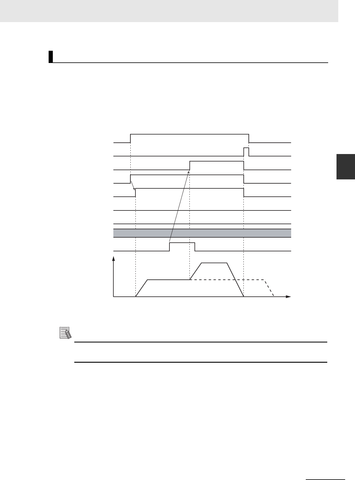
3-115
3 Axis Command Instructions
NJ/NX-series Motion Control Instructions Reference Manual (W508)
MC_MoveFeed
3
Function
• Busy (Executing) changes to TRUE at the same time as Execute changes to TRUE. Active (Con-
trolling) changes to TRUE in the next period.
• After an interrupt input, InFeed changes to TRUE and when FeedDistance is reached and positioning
is completed, Done changes to TRUE.
• If another instruction aborts this instruction, CommandAborted changes to TRUE and Busy (Execut-
ing) and Active (Controlling) change to FALSE.
When MoveMode (Travel Mode) is _mcAbsolute or _mcRelative
* There may be a delay of up to several control periods from when the interrupt input turns ON until InFeed
changes to TRUE.
Additional Information
Acceleration or deceleration to interrupt feeding is performed according to the Acceleration
(Acceleration Rate) or Deceleration (Deceleration Rate) input variable.
Timing Charts
Time
Velocity
Interrupt input
*
Busy
CommandAborted
InFeed
Error
16#0000
ErrorID
Execute
Done
Active

3 Axis Command Instructions
3-116
NJ/NX-series Motion Control Instructions Reference Manual (W508)
When MoveMode (Travel Mode) is _mcVelocity
Operation Selection at Reversing Axis Parameter
When feeding reverses its direction after the interrupt input, operation follows the Operation Selec-
tion at Reversing axis parameter
When Motion Variable Is 0 (Decelerate to a Stop After Reversing)
Time
Velocity
Interrupt input
Busy
CommandAborted
InFeed
Error
16#0000
ErrorID
Execute
Done
Active
Time
Velocity
Interrupt input
Busy
CommandAborted
InFeed
Error
16#0000
ErrorID
Execute
Done
Active

3-117
3 Axis Command Instructions
NJ/NX-series Motion Control Instructions Reference Manual (W508)
MC_MoveFeed
3
Function
Additional Information
The deceleration rate when the axis reverses after an interrupt input follows the Deceleration
(Deceleration Rate) input variable.
When Motion Variable Is 1 (Stop Immediately After Reversing)
Time
Velocity
Interrupt input
Busy
CommandAborted
InFeed
Error
16#0000
ErrorID
Execute
Done
Active

3 Axis Command Instructions
3-118
NJ/NX-series Motion Control Instructions Reference Manual (W508)
When MoveMode (Travel Mode) is _mcAbsolute and an Interrupt Input Is Not
Received
When ErrorDetect (Error Detection Selection) Is Set to Not Detect Errors
When ErrorDetect (Error Detection Selection) Is Set to Detect Errors
Time
Velocity
Interrupt input
Busy
CommandAborted
InFeed
Error
16#0000
ErrorID
Execute
Done
Active
Time
Velocity
Interrupt input
Busy
CommandAborted
InFeed
Error
16#0000
ErrorID
Execute
Done
Active

3-119
3 Axis Command Instructions
NJ/NX-series Motion Control Instructions Reference Manual (W508)
MC_MoveFeed
3
Function
When WindowOnly Is Enabled
Busy
CommandAborted
InFeed
Error
16#0000
ErrorID
Execute
Done
Active
LastPosition
FirstPosition
Velocity
Time
Interrupt input
Position
Time

3 Axis Command Instructions
3-120
NJ/NX-series Motion Control Instructions Reference Manual (W508)
This instruction cannot be re-executed.
A Motion Control Instruction Re-execution Disabled error (error code: 543B hex) occurs if re-execution
is attempted.
For details on multi-execution of motion control instructions, refer to the NJ/NX-series CPU Unit Motion
Control User’s Manual (Cat. No. W507) or NY-series Industrial Panel PC / Industrial Box PC Motion
Control User’s Manual (Cat. No. W559).
Execution during Execution of Other Instructions
You can switch to this instruction or buffer this instruction if you execute it during execution of
another instruction. You can buffer one instruction per axis. Specify the operation of this instruction
using BufferMode (Buffer Mode Selection) for multi-execution of instructions.
For details on BufferMode (Buffer Mode Selection), refer to the NJ/NX-series CPU Unit Motion Con-
trol User's Manual (Cat. No. W507) or NY-series Industrial Panel PC / Industrial Box PC Motion Con-
trol User’s Manual (Cat. No. W559).
Execution of Other Instructions during Instruction Execution
You can execute another instruction with the Buffer Mode set to Aborting during execution of this
instruction.
The following will occur if another instruction with the Buffer Mode set to Buffered or a blending
mode is executed.
• Error changes to TRUE in the other instruction. A Motion Control Instruction Multi-execution Dis-
abled error (error code: 543C hex) is output to ErrorID (Error Code).
• The MC_MoveFeed instruction is aborted and CommandAborted changes to TRUE.
Re-execution of Motion Control Instructions
Multi-execution of Motion Control Instructions
Buffer Mode Selection Description
Aborting Aborts the instruction being executed and switches to this instruction.
If the direction of axis motion is reversed by switching instructions, the motion will be
reversed according to the Operation Selection at Reversing axis parameter.
Buffered Buffers this instruction and executes it automatically after the current instruction is
completed.

3-121
3 Axis Command Instructions
NJ/NX-series Motion Control Instructions Reference Manual (W508)
MC_MoveFeed
3
Function
If an error occurs during instruction execution, Error will change to TRUE and the axis will stop. You can
find out the cause of the error by referring to the value output by ErrorID (Error Code).
Timing Chart When Error Occurs
When there is an error, the latch used for the interrupt input for this instruction is disabled.
Error Codes
Refer to A-1 Error Codes for instruction errors.
Errors
Error code
Busy
Done
CommandAborted
Error
16#0000
ErrorID
Execute
Active

3 Axis Command Instructions
3-122
NJ/NX-series Motion Control Instructions Reference Manual (W508)
This section shows sample programming where control changes from velocity control to interrupt feed-
ing.
The minimum settings required for this sample programming are given below.
Setting Axis Parameters
Axis Types
Count Modes
Ring Counters
Units of Display
Sample Programming
Parameter Settings
Axis Axis Type
Axis 1 Servo axis
Axis 2 Servo axis
Axis Count Mode
Axis 1 Rotary Mode
Axis 2 Linear Mode
Axis
Modulo maximum
position
Modulo mini-
mum position
Axis 1 360 0
Axis Unit of Display
Axis 1 degree
Axis 2 mm
Operation Example
Sensor 1
Axis 1
Axis 2

3-123
3 Axis Command Instructions
NJ/NX-series Motion Control Instructions Reference Manual (W508)
MC_MoveFeed
3
Sample Programming
Operation Pattern
1
Conveyor Operation
Axis 1, which moves the conveyer belt, performs velocity control before interrupt feeding.
2
Feeding
Sensor 1 is connected to latch 1.
When Sensor1 turns ON, operation changes to feeding and the axis stops at the specified posi-
tion.
3
Pressing the Stamp
When positioning is finished, axis 2 of the stamp moves perpendicularly down at the position
determined by absolute positioning to press the stamp.
After stamping is performed, axis 2 returns to home.
When the absolute positioning is completed, the axis is immediately returned to home. To enable
this, BufferMode (Buffer Mode Selection) of the MC_MoveZeroPosition (High-speed Home) instruc-
tion is set to Buffered. Multi-execution of instructions is performed if the Active output from the previ-
ous instruction is TRUE.
Main Variables
Ladder Diagram
Name Data type Default Comment
MC_Axis000 _sAXIS_REF --- Axis Variable for axis 1.
MC_Axis000.MFaultLvl.Active BOOL FALSE TRUE while there is a minor fault level error for
axis 1.
MC_Axis000.Details.Homed BOOL FALSE TRUE when home is defined for axis 1.
MC_Axis001 _sAXIS_REF --- Axis Variable for axis 2.
MC_Axis001.MFaultLvl.Active BOOL FALSE TRUE while there is a minor fault level error for
axis 2.
MC_Axis001.Details.Homed BOOL FALSE TRUE when home is defined for axis 2.
TrigRef _sTRIG-
GER_REF
--- This is the specified variable for the interrupt
input. Latch 1 of the Servo Drive is used in this
sample. When the rising edge of the external
input for sensor 1 is detected, interrupt feeding is
executed.
StartPg BOOL FALSE The Servo is turned ON if this variable is TRUE
and EtherCAT process data communications are
established.
Time
Velocity
Sensor operation
Stamp
Velocity control
Position control

3 Axis Command Instructions
3-124
NJ/NX-series Motion Control Instructions Reference Manual (W508)
Timing Chart
InitFlag BOOL FALSE This variable indicates if it is necessary to set the
input parameters. Input parameters are set when
this variable is FALSE. When setting the input
parameters is completed, this variable changes to
TRUE.
Name Data type Default Comment
Mv_Zero_Bsy
Mv_Zero_D
Mv_Zero_Act
Mv_Abs_D
Mv_Abs_Act
Hm2_D
Mv_Feed_D
Mv_Abs_Bsy
Mv_Feed_Bsy
Mv_Feed_InFeed
Hm1_D
Mv_Feed_Act
MC_Axis000
MC_Axis001
Velocity
Time
Velocity
Time
Sensor 1
command current velocity
command current velocity

3-125
3 Axis Command Instructions
NJ/NX-series Motion Control Instructions Reference Manual (W508)
MC_MoveFeed
3
Sample Programming
Sample Programming
PWR1
Error
Axis Axis
Enable Status
Busy
MC_Power
ErrorID
Lock1
MC_Axis000
Pwr1_Status
Pwr1_Bsy
Pwr1_Err
Pwr1_ErrID
StartPg
Lock1
MC_Axis000.DrvStatus.Ready
Lock2
MC_Axis001.DrvStatus.Ready
If the Servo Drives are ready, the Servos are turned ON for each axis.
If StartPg is TRUE, check that the Servo Drives for each axis are ready.

3 Axis Command Instructions
3-126
NJ/NX-series Motion Control Instructions Reference Manual (W508)
FaultHandlerMC_Axis000.MFaultLvl.Active
FaultHandlerEN
MC_Axis001.MFaultLvl.Active
HM1
Axis Axis
Execute
Error
ErrorID
CommandAborted
MC_Home
Done
Busy
MC_Axis000
Pwr1_Status
Hm1_D
Hm1_Bsy
Hm1_Ca
Hm1_Err
Hm1_ErrID
MC_Axis000.Details.Homed
HM2
Axis Axis
Execute
Error
ErrorID
CommandAborted
MC_Home
Done
Busy
MC_Axis001
Pwr2_Status
Hm2_D
Hm2_Bsy
Hm2_Ca
Hm2_Err
Hm2_ErrID
MC_Axis001.Details.Homed
InitFlag
PWR2
Error
Axis Axis
Enable Status
Busy
MC_Power
ErrorID
Lock2
MC_Axis001
Pwr2_Status
Pwr2_Bsy
Pwr2_Err
Pwr2_ErrID
The parameters are set for interrupt feeding, absolute positioning, and high-speed homing.
If a minor fault level error occurs for the axis composition, the error handler for the device (FaultHandler) is executed.
Program the FaultHandler according to the device.
If the Servo is ON for axis 1 and home is not defined, the Home instruction is executed.
If the Servo is ON for axis 2 and home is not defined, the Home instruction is executed.
Note: The contents of the inline ST are given below.

3-127
3 Axis Command Instructions
NJ/NX-series Motion Control Instructions Reference Manual (W508)
MC_MoveFeed
3
Sample Programming
Contents of Inline ST
// MV_FEED parameters
Mv_Feed_TrigRef.Mode := _eMC_TRIGGER_MODE#_mcDrive;
Mv_Feed_TrigRef.LatchID := _eMC_TRIGGER_LATCH_ID#_mcLatch1;
Mv_Feed_TrigRef.InputDrive := _eMC_TRIGGER_INPUT_DRIVE#_mcEXT;
Mv_Feed_TrigVar := FALSE;
Mv_Feed_Pos := LREAL#2000.0;
Mv_Feed_Vel := LREAL#1000.0;
Mv_Feed_Acc := LREAL#10000.0;
Mv_Feed_Dec := LREAL#10000.0;
Mv_Feed_Mm := _eMC_MOVE_MODE#_mcVelocity;
Mv_Feed_FeedDis := LREAL#500.0;
Mv_Zero_Bsy
Mv_Zero_Act
Mv_Zero_Ca
Mv_Zero_Err
Mv_Zero_ErrID
Mv_Zero_D
Mv_Zero_Vel
Mv_Zero_Acc
Mv_Zero_Dec
Mv_Zero_Jrk
Mv_Zero_Bm
MV_ZERO
Jerk
Active
Axis Axis
Execute Done
Velocity Busy
Deceleration
Error
BufferMode
MC_MoveZeroPosition
Acceleration
CommandAborted
ErrorID
MC_Axis001
Mv_Abs_Act
BufferMode
MV_ABS
Deceleration
Active
Axis Axis
Execute Done
Position Busy
Acceleration
Error
Jerk
Direction
MC_MoveAbsolute
Velocity
CommandAborted
ErrorID
MC_Axis001
Mv_Abs_Pos
Mv_Abs_Vel
Mv_Abs_Acc
Mv_Abs_Dec
Mv_Abs_Jrk
Mv_Abs_Bsy
Mv_Abs_Act
Mv_Abs_Ca
Mv_Abs_Err
Mv_Abs_ErrID
Mv_Abs_D
Mv_Feed_DMC_Axis001.Details.Homed
Mv_Feed_Bsy
Mv_Feed_Act
Mv_Feed_Ca
Mv_Feed_Err
Mv_Feed_ErrID
Position
Velocity
Acceleration
Deceleration
Jerk
MV_FEED
FirstPosition
Axis Axis
TriggerInput TriggerInput
TriggerVariable TriggerVariable
WindowOnly
Error
ErrorID
CommandAborted
LastPosition Active
ReferenceType
MC_MoveFeed
Execute Done
Busy
Direction
MoveMode
FeedDistance
FeedVelocity
BufferMode
ErrorDetect
InFeed
MC_Axis000
Mv_Feed_TrigRef
Mv_Feed_TrigVar
Mv_Feed_Pos
Mv_Feed_Vel
Mv_Feed_Acc
Mv_Feed_Dec
Mv_Feed_Mm
Mv_Feed_FeedDis
Mv_Feed_FeedVel
Mv_Feed_D
Mv_Feed_InFeed
MC_Axis000.Details.Homed
If home is defined for axis 2 and interrupt feeding is completed for axis 1, absolute positioning is performed for axis 2.
After absolute positioning is completed, the High-speed Home instruction is executed to move to home.
If home is defined for axis 1, interrupt feeding is executed for axis 1.

3 Axis Command Instructions
3-128
NJ/NX-series Motion Control Instructions Reference Manual (W508)
Mv_Feed_FeedVel := LREAL#500.0;
// MV_ABS parameters
Mv_Abs_Pos := LREAL#1000.0;
Mv_Abs_Vel := LREAL#500.0;
Mv_Abs_Acc := LREAL#10000.0;
Mv_Abs_Dec := LREAL#10000.0;
Mv_Abs_Jrk := LREAL#10000.0;
// MV_ZERO parameters
Mv_Zero_Vel := LREAL#500.0;
Mv_Zero_Acc := LREAL#10000.0;
Mv_Zero_Dec := LREAL#10000.0;
Mv_Zero_Jrk := LREAL#10000.0;
Mv_Zero_Bm := _eMC_BUFFER_MODE#_mcBuffered;
// Change InitFlag to TRUE after setting the input parameters.
InitFlag := TRUE;
Main Variables
Structured Text (ST)
Name Data type Default Comment
MC_Axis000 _sAXIS_REF --- Axis Variable for axis 1.
MC_Axis000.MFaultLvl.Active BOOL FALSE TRUE while there is a minor fault level error for
axis 1.
MC_Axis000.Details.Homed BOOL FALSE TRUE when home is defined for axis 1.
MC_Axis001 _sAXIS_REF --- Axis Variable for axis 2.
MC_Axis001.MFaultLvl.Active BOOL FALSE TRUE while there is a minor fault level error for
axis 2.
MC_Axis001.Details.Homed BOOL FALSE TRUE when home is defined for axis 2.
TrigRef _sTRIG-
GER_REF
--- This is the specified variable for the interrupt
input. Latch 1 of the Servo Drive is used in this
sample. When the rising edge of the external
input for sensor 1 is detected, interrupt feeding is
executed.
StartPg BOOL FALSE The Servo is turned ON if this variable is TRUE
and EtherCAT process data communications are
established.
InitFlag BOOL FALSE This variable indicates if it is necessary to set the
input parameters. Input parameters are set when
this variable is FALSE. When setting the input
parameters is completed, this variable changes to
TRUE.
Hm1_Ex BOOL FALSE The HM1 instance of MC_Home is executed
when this variable changes to TRUE.
Hm2_Ex BOOL FALSE The HM2 instance of MC_Home is executed
when this variable changes to TRUE.
Mv_Feed_Ex BOOL FALSE The MV_FEED instance of MC_MoveFeed is
executed when this variable changes to TRUE.
Mv_Abs_Ex BOOL FALSE The MV_ABS instance of MC_MoveAbsolute is
executed when this variable changes to TRUE.
Mv_Zero_Ex BOOL FALSE The MV_ZERO instance of MC_MoveZeroPosi-
tion is executed when this variable changes to
TRUE.

3-129
3 Axis Command Instructions
NJ/NX-series Motion Control Instructions Reference Manual (W508)
MC_MoveFeed
3
Sample Programming
Timing Chart
Sample Programming
// Processing when input parameters are not set
IF InitFlag=FALSE THEN
// MV_FEED parameters
Mv_Feed_TrigRef.Mode := _eMC_TRIGGER_MODE#_mcDrive;
Mv_Feed_TrigRef.LatchID := _eMC_TRIGGER_LATCH_ID#_mcLatch1;
Mv_Feed_TrigRef.InputDrive := _eMC_TRIGGER_INPUT_DRIVE#_mcEXT;
Mv_Feed_TrigVar := FALSE;
Mv_Feed_Pos := LREAL#2000.0;
Mv_Feed_Vel := LREAL#1000.0;
Mv_Feed_Acc := LREAL#10000.0;
Mv_Feed_Dec := LREAL#10000.0;
Mv_Feed_Mm := _eMC_MOVE_MODE#_mcVelocity;
Mv_Feed_FeedDis := LREAL#500.0;
Mv_Feed_FeedVel := LREAL#500.0;
Mv_Zero_Bsy
Mv_Zero_D
Mv_Zero_Act
Mv_Zero_Ex
Mv_Abs_D
Mv_Abs_Act
Mv_Abs_Ex
Mv_Feed_InFeed
Hm2_D
Hm1_D
Mv_Abs_Bsy
Mv_Feed_Bsy
Mv_Feed_D
Mv_Feed_Ex
Mv_Feed_Act
MC_Axis000
MC_Axis001
Velocity
Time
Velocity
Time
command current velocity
command current velocity
Sensor 1

3 Axis Command Instructions
3-130
NJ/NX-series Motion Control Instructions Reference Manual (W508)
// MV_ABS parameters
Mv_Abs_Pos := LREAL#1000.0;
Mv_Abs_Vel := LREAL#500.0;
Mv_Abs_Acc := LREAL#10000.0;
Mv_Abs_Dec := LREAL#10000.0;
Mv_Abs_Jrk := LREAL#10000.0;
// MV_ZERO parameters
Mv_Zero_Vel := LREAL#500.0;
Mv_Zero_Acc := LREAL#10000.0;
Mv_Zero_Dec := LREAL#10000.0;
Mv_Zero_Jrk := LREAL#10000.0;
Mv_Zero_Bm := _eMC_BUFFER_MODE#_mcBuffered;
// Change InitFlag to TRUE after setting the input parameters.
InitFlag := TRUE;
END_IF;
// If StartPg is TRUE and the Servo Drive is ready, the Servo for axis 1 is turned ON.
// If the Servo Drive is not ready, the Servo is turned OFF.
IF (StartPg=TRUE)
AND (MC_Axis000.DrvStatus.Ready=TRUE) THEN
Pwr1_En:=TRUE; // Turn ON the Servo.
ELSE
Pwr1_En:=FALSE; // Turn OFF the Servo.
END_IF;
// If StartPg is TRUE and the Servo Drive is ready, the Servo for axis 2 is turned ON.
// If the Servo Drive is not ready, the Servo is turned OFF.
IF (StartPg=TRUE)
AND (MC_Axis001.DrvStatus.Ready=TRUE) THEN
Pwr2_En:=TRUE; // Turn ON the Servo for axis 2.
ELSE
Pwr2_En:=FALSE; // Turn OFF the Servo for axis 2.
END_IF;
// Processing for a minor fault level error
// Program the FaultHandler according to the device.
IF (MC_Axis000.MFaultLvl.Active=TRUE) OR (MC_Axis001.MFaultLvl.Active=TRUE) THEN
FaultHandler();
END_IF;
// If the Servo is ON for axis 1 and home is not defined, the Home instruction is executed for axis 1.
IF (Pwr1_Status=TRUE) AND (MC_Axis000.Details.Homed=FALSE) THEN
Hm1_Ex:=TRUE;
END_IF;
// If the Servo is ON for axis 2 and home is not defined, the Home instruction is executed for axis 2.
IF (Pwr2_Status=TRUE) AND (MC_Axis001.Details.Homed=FALSE) THEN
Hm2_Ex:=TRUE;
END_IF;
// After home is defined for axis 1, MC_MoveFeed is executed.
IF MC_Axis000.Details.Homed=TRUE THEN
Mv_Feed_Ex:=TRUE;
END_IF;

3-131
3 Axis Command Instructions
NJ/NX-series Motion Control Instructions Reference Manual (W508)
MC_MoveFeed
3
Sample Programming
// If home is defined for axis 2 and interrupt feeding is completed for axis 1, absolute positioning is performed for
axis 2.
IF (MC_Axis001.Details.Homed=TRUE) AND (Mv_Feed_D=TRUE) THEN
Mv_Abs_Ex := TRUE;
END_IF;
// After MC_MoveAbsolute is started, MC_MoveZeroPosition is executed with multi-execution of instructions.
IF Mv_Abs_Act=TRUE THEN
Mv_Zero_Ex := TRUE;
END_IF;
// MC_Power for axis 1
PWR1(
Axis := MC_Axis000,
Enable := Pwr1_En,
Status => Pwr1_Status,
Busy => Pwr1_Bsy,
Error => Pwr1_Err,
ErrorID => Pwr1_ErrID
);
// MC_Power for axis 2
PWR2(
Axis := MC_Axis001,
Enable := Pwr2_En,
Status => Pwr2_Status,
Busy => Pwr2_Bsy,
Error => Pwr2_Err,
ErrorID => Pwr2_ErrID
);
// MC_Home for axis 1
HM1(
Axis := MC_Axis000,
Execute := Hm1_Ex,
Done => Hm1_D,
Busy => Hm1_Bsy,
CommandAborted => Hm1_Ca,
Error => Hm1_Err,
ErrorID => Hm1_ErrID
);
// MC_Home for axis 2
HM2(
Axis := MC_Axis001,
Execute := Hm2_Ex,
Done => Hm2_D,
Busy => Hm2_Bsy,
CommandAborted => Hm2_Ca,
Error => Hm2_Err,
ErrorID => Hm2_ErrID
);
// MC_MoveFeed
MV_FEED(
Axis := MC_Axis000,
TriggerInput := Mv_Feed_TrigRef,
TriggerVariable := Mv_Feed_TrigVar,
Execute := Mv_Feed_Ex,
Position := Mv_Feed_Pos,

3 Axis Command Instructions
3-132
NJ/NX-series Motion Control Instructions Reference Manual (W508)
Velocity := Mv_Feed_Vel,
Acceleration := Mv_Feed_Acc,
Deceleration := Mv_Feed_Dec,
MoveMode := Mv_Feed_Mm,
FeedDistance := Mv_Feed_FeedDis,
FeedVelocity := Mv_Feed_FeedVel,
Done => Mv_Feed_D,
InFeed => Mv_Feed_InFeed,
Busy => Mv_Feed_Bsy,
Active => Mv_Feed_Act,
CommandAborted => Mv_Feed_Ca,
Error => Mv_Feed_Err,
ErrorID => Mv_Feed_ErrID
);
// MC_MoveAbsolute
MV_ABS(
Axis := MC_Axis001,
Execute := Mv_Abs_Ex,
Position := Mv_Abs_Pos,
Velocity := Mv_Abs_Vel,
Acceleration := Mv_Abs_Acc,
Deceleration := Mv_Abs_Dec,
Jerk := Mv_Abs_Jrk,
Done => Mv_Abs_D,
Busy => Mv_Abs_Bsy,
Active => Mv_Abs_Act,
CommandAborted => Mv_Abs_Ca,
Error => Mv_Abs_Err,
ErrorID => Mv_Abs_ErrID
);
// MC_MoveZeroPosition
MV_ZERO(
Axis := MC_Axis001,
Execute := Mv_Zero_Ex,
Velocity := Mv_Zero_Vel,
Acceleration := Mv_Zero_Acc,
Deceleration := Mv_Zero_Dec,
Jerk := Mv_Zero_Jrk,
BufferMode := Mv_Zero_Bm,
Done => Mv_Zero_D,
Busy => Mv_Zero_Bsy,
Active => Mv_Zero_Act,
CommandAborted => Mv_Zero_Ca,
Error => Mv_Zero_Err,
ErrorID => Mv_Zero_ErrID
);

3 Axis Command Instructions
3-133
NJ/NX-series Motion Control Instructions Reference Manual (W508)
MC_Stop
3
Variables
MC_Stop
The MC_Stop instruction decelerates an axis to a stop.
*1 Refer to Unit Conversion Settings in the NJ/NX-series CPU Unit Motion Control User's Manual (Cat. No. W507) or NY-
series Industrial Panel PC / Industrial Box PC Motion Control User’s Manual (Cat. No. W559) for information on command
units.
*2 The default value for an enumeration variable is actually not the number, but the enumerator.
*Refer to A-1 Error Codes.
Instruction Name FB/FUN Graphic expression ST expression
MC_Stop Stop FB MC_Stop_instance (
Axis :=parameter,
Execute :=parameter,
Deceleration :=parameter,
Jerk :=parameter,
BufferMode :=parameter,
Done =>parameter,
Busy =>parameter,
Active =>parameter,
CommandAborted =>parameter,
Error =>parameter,
ErrorID =>parameter
);
Variables
Input Variables
Name Meaning Data type Valid range Default Description
Execute Execute BOOL TRUE or
FALSE
FALSE The instruction is executed when
Execute changes to TRUE.
Deceleration Deceleration
Rate
LREAL Non-negative
number
0 Specify the deceleration rate. The
unit is command units/s
2
.
*1
Jerk Jerk LREAL Non-negative
number
0 Specify the jerk. The unit is com-
mand units/s
3
.
*1
BufferMode Buffer Mode
Selection
_eMC_BUFFER_
MODE
0: _mcAborting
0
*2
Specify the behavior when executing
more than one motion instruction.
0: Aborting
Output Variables
Name Meaning Data type Valid range Description
Done Done BOOL TRUE or FALSE TRUE when the instruction is completed.
Busy Executing BOOL TRUE or FALSE TRUE when the instruction is acknowledged.
Active Controlling BOOL TRUE or FALSE TRUE when the axis is being controlled.
CommandAborted Command
Aborted
BOOL TRUE or FALSE TRUE when the instruction is aborted.
Error Error BOOL TRUE or FALSE TRUE while there is an error.
ErrorID Error Code WORD
*
Contains the error code when an error occurs.
A value of 16#0000 indicates normal execution.
MC_Stop_instance
Axis Axis
Execute Done
Deceleration
BufferMode
Error
ErrorID
CommandAborted
Active
MC_Stop
Jerk
Busy

3 Axis Command Instructions
3-134
NJ/NX-series Motion Control Instructions Reference Manual (W508)
Output Variable Update Timing
* Specify a user-defined Axis Variable that was created in the Axis Basic Settings of the Sysmac Studio (default: MC_Axis***)
or a system-defined axis variable name (_MC_AX[*], _MC1_AX[*], or _MC2_AX[*]).
• The MC_Stop instruction decelerates an axis from the current velocity to a velocity of 0.
• The deceleration stop operation starts when Execute changes to TRUE.
• CommandAborted for the instruction that is currently in operation will change to TRUE when
MC_Stop is executed.
Precautions for Correct UsePrecautions for Correct Use
You cannot execute this instruction if the Status.ErrorStop (Error Deceleration Stopping) variable
that gives the status of this axis is TRUE.
Use the MC_ImmediateStop instruction to stop the motion of an axis that is decelerating to a
stop for an error.
Name Timing for changing to TRUE Timing for changing to FALSE
Done When the axis decelerates to a stop and the velocity
reaches 0.
• When Execute is TRUE and changes to
FALSE.
• After one period when Execute is FALSE.
Busy When Execute changes to TRUE. • When Done changes to TRUE.
• When Error changes to TRUE.
• When CommandAborted changes to
TRUE.
Active When the instruction is started. • When Done changes to TRUE.
• When Error changes to TRUE.
• When CommandAborted changes to
TRUE.
CommandAborted • When this instruction is aborted because another
MC_Stop instruction was executed with the Buffer
Mode set to Aborting.
• When this instruction is canceled due to an error.
• When this instruction is executed while there is an
error.
• When Execute is TRUE and changes to
FALSE.
• After one period when Execute is FALSE.
Error When there is an error in the execution conditions or
input parameters for the instruction.
When the error is cleared.
In-Out Variables
Name Meaning Data type Valid range Description
Axis Axis _sAXIS_REF ---
Specify the axis.
*
Function

3 Axis Command Instructions
3-135
NJ/NX-series Motion Control Instructions Reference Manual (W508)
MC_Stop
3
Function
This section describes the instruction in detail.
Specifying Deceleration and Jerk
Set the input variables Deceleration and Jerk to set the deceleration rate and jerk when decelerating
to a stop.
The relationship between the deceleration and velocity when Jerk is set to 0 and when it is set to any
other value is shown below.
Jerk Set to 0
The command value for the velocity is created with deceleration rate Dt.
Vt: Velocity when deceleration starts, Dt: Specified deceleration rate, Jt: Specified jerk
Jerk Set to Any Value Other Than 0
The command value for the velocity is created based on the current velocity with Dt as the upper
limit to the deceleration rate.
Vt: Velocity when deceleration starts, Dt: Specified deceleration rate, Jt: Specified jerk
Instruction Details
Vt
-Dt
Jt = 0
Time
Time
Time
Velocity
Jerk
Decelera-
tion rate
Velocity
Vt
-Dt
Jt
-Jt
Time
Time
TimeVelocity
Deceleration rate
Jerk
Velocity

3 Axis Command Instructions
3-136
NJ/NX-series Motion Control Instructions Reference Manual (W508)
Additional Information
If you set the deceleration to 0, an Immediate Stop instruction is executed. This will stop the axis
immediately without decelerating. An immediate stop occurs regardless of the setting of the
Acceleration/Deceleration Over Limit Selection only when the deceleration rate is set to 0.
Specifying BufferMode (Buffer Mode Selection)
BufferMode specifies how to join the axis motions for this instruction and the previous instruction.
BufferMode (Buffer Mode Selection) of this instruction is a reserved parameter for future expansion.
There is currently only the following setting.
For details on BufferMode (Buffer Mode Selection), refer to the NJ/NX-series CPU Unit Motion Con-
trol User's Manual (Cat. No. W507) or NY-series Industrial Panel PC / Industrial Box PC Motion Con-
trol User’s Manual (Cat. No. W559).
In-position Check
An in-position check is not performed when stopping for this instruction.
Buffer Mode Selection Description
Aborting Aborts the instruction being executed and executes this instruction.

3 Axis Command Instructions
3-137
NJ/NX-series Motion Control Instructions Reference Manual (W508)
MC_Stop
3
Function
• Busy (Executing) changes to TRUE at the same time as Execute changes to TRUE. Active (Con-
trolling) changes to TRUE in the next period.
• Done changes to TRUE when a velocity of 0 is reached.
• If another instruction aborts this instruction, CommandAborted changes to TRUE and Busy (Execut-
ing) and Active (Controlling) change to FALSE.
Timing Charts
Time
Velocity
Executing MC_Stop Instruction
Executing an Axis Instruction
Busy
Done
CommandAborted
Active
Error
16#0000
ErrorID
Execute
Busy
Done
CommandAborted
Active
Error
16#0000
ErrorID
Execute

3 Axis Command Instructions
3-138
NJ/NX-series Motion Control Instructions Reference Manual (W508)
Deceleration (Deceleration Rate) changes if Execute is changed to TRUE again while this instruction is
in execution. The Jerk setting is not changed when a motion control instruction is re-executed.
Jerk Set to Any Value Other Than 0
The command value for the velocity is created based on the current velocity and deceleration rate,
with Dt2 as the upper limit to the deceleration rate after it is changed.
Vt: Velocity when deceleration starts, Dt: Specified deceleration rate, Jt: Specified jerk
For details on multi-execution of motion control instructions, refer to the NJ/NX-series CPU Unit Motion
Control User's Manual (Cat. No. W507) or NY-series Industrial Panel PC / Industrial Box PC Motion
Control User’s Manual (Cat. No. W559).
Execution during Execution of Other Instructions
Axes Group Moving
If the MC-Stop instruction is executed for an axis that is in an axes group motion, an error will occur
for the axis. An error will occur also for the axes group, and the axes group motion will stop.
When the Status.ErrorStop (Error Deceleration Stop) Axis Variable Is TRUE
Status.ErrorStop (Error Deceleration Stopping) in the Axis Variable is TRUE while there is an error
for the axis. If the MC_Stop instruction is not executed normally for an axis that is decelerating to a
stop for an error. CommandAborted changes to TRUE. Use the MC_ImmediateStop instruction to
stop the motion of an axis for which an error occurred.
During Execution of the MC_ResetFollowingError (Reset Following Error
Counter) Instruction
If the MC_Stop instruction is executed during the MC_ResetFollowingError (Reset Following Error
Counter) instruction, CommandAborted from the MC_ResetFollowingError instruction changes to
TRUE. The MC_Stop instruction is executed. However, Deceleration (Deceleration Rate) to the
MC_Stop instruction is not used and an immediate stop is performed.
Re-execution of Motion Control Instructions
Multi-execution of Motion Control Instructions
Time
Time
Time
Velocity
Jerk
Deceleration rate
Velocity
Vt
-Dt1
Jt
-Jt
-Dt2
Executed.
Re-executed.

3 Axis Command Instructions
3-139
NJ/NX-series Motion Control Instructions Reference Manual (W508)
MC_Stop
3
Function
Execution of Other Instructions during Instruction Execution
• If any of the following is executed while the axis is not decelerating to a stop for an MC_Stop
instruction, Status.Stopping in the Axis Variable changes to TRUE.
MC_ResetFollowingError (Reset Following Error Counter) instruction
An immediate stop for the MC_TouchProbe (Enable External Latch) instruction
When Execute is TRUE for any other MC_Stop instruction
• Operation is as follows for an axis for which Status.Stopping (Deceleration Stopping) is TRUE.
• If single-axis positioning, continuous positioning, synchronized operation, or manual operation
is performed, CommandAborted from the instruction changes to TRUE.
• If the MC_ResetFollowingError (Reset Following Error Counter) instruction is executed during
MC_Stop instruction execution, Done from the MC_Stop instruction changes to TRUE and the
MC_ResetFollowingError instruction is executed.
• Multi-execution of more than one MC_Stop Instruction is possible. Done from the first
MC_Stop instruction changes to TRUE.
• Done of the MC_Stop instruction changes to TRUE when one of the following conditions is met
after the MC_Stop instruction is executed.
• When the Enable input variable for the MC_Power instruction changes to FALSE (when the
Servo is turned OFF)
• When _mcImmediateStop is selected for the StopMode input variable to the MC_TouchProbe
(Enable External Latch) instruction, the trigger condition is met, and the OMRON 1S-series
Servo Drive or G5-series Servo Drive stops immediately

3 Axis Command Instructions
3-140
NJ/NX-series Motion Control Instructions Reference Manual (W508)
Operation will stop if an error (e.g., axis error) occurs during instruction execution.
Specify the stopping method in the axis parameters. The stopping method can be immediate stop,
deceleration stop, or Servo OFF. If you specify a deceleration stop, the axis will continue decelerating
until it stops.
For details on setting the Stop Mode in the axis parameters, refer to the NJ/NX-series CPU Unit Motion
Control User's Manual (Cat. No. W507) or NY-series Industrial Panel PC / Industrial Box PC Motion
Control User’s Manual (Cat. No. W559).
Timing Chart When Error Occurs
If an error occurs during instruction execution, Error will change to TRUE and the axis will stop. You
can find out the cause of the error by referring to the value output by ErrorID (Error Code).
Errors
Velocity
Time
Error code
Busy
CommandAborted
Active
Error
ErrorID
Execute
Busy
Done
CommandAborted
Active
Error
ErrorID
Execute
MC_Stop
16#0000
MC_MoveVelocity
16#0000
The current instruction is stopped for an
error if an axis error occurs.
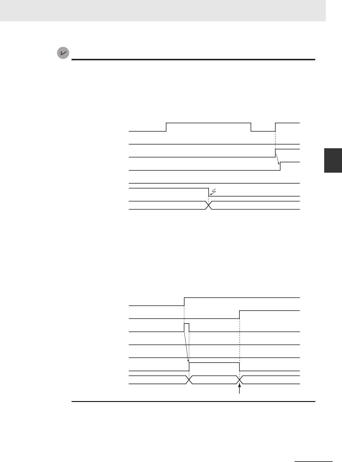
3 Axis Command Instructions
3-141
NJ/NX-series Motion Control Instructions Reference Manual (W508)
MC_Stop
3
Function
Version Information
Operation when an error is reset depends on the unit version of the CPU Unit as follows:
Note that you must reset errors only after the axis has stopped. Do not reset errors during axis
motion.
• A CPU Unit with unit version 1.10 or later:
If you clear the error for this instruction, the instruction will not start until Execute changes to
TRUE again.
• A CPU Unit with unit version 1.09 or earlier:
If an error occurs for this instruction and the error is reset while Execute is TRUE, operation
will be performed as follows.
• If the cause of the error has already been removed, Error changes to FALSE and Done
changes to TRUE. Status.Stopping (Deceleration Stopping) in the Axis Variable changes
to TRUE in the same way as for normal execution of the deceleration stop.
• If the cause of the error has not been removed, Error changes to TRUE again for this
instruction and an axis error occurs.
In the following timing chart, the cause of the error is removed.
Error Codes
Refer to A-1 Error Codes for instruction errors.
16#0000
Execute
Busy
Active
Done
CommandAborted
Error
ErrorID
Error reset.
Error code
Ver. 1.10 or Later
Busy
Done
CommandAborted
Active
Error
16#0000
ErrorID
Execute
16#0000
Ver. 1.09 or Earlier
Error code
Error reset.

3 Axis Command Instructions
3-142
NJ/NX-series Motion Control Instructions Reference Manual (W508)
MC_ImmediateStop
The MC_ImmediateStop instruction stops an axis according to the stopping mode that is set with the
StopMode (Stopping Mode Selection) input variable regardless of the status of the axis.
* The default value for an enumeration variable is actually not the number, but the enumerator.
* Refer to A-1 Error Codes.
Instruction Name
FB/
FUN
Graphic expression ST expression
MC_ImmediateStop Immediate
Stop
FB MC_ImmediateStop_instance (
Axis :=parameter,
Execute :=parameter,
StopMode :=parameter,
Done =>parameter,
Busy =>parameter,
CommandAborted
=>parameter,
Error =>parameter,
ErrorID =>parameter
);
Variables
Input Variables
Name Meaning Data type Valid range Default Description
Execute Execute BOOL TRUE or FALSE FALSE The instruction is executed when
Execute changes to TRUE.
StopMode Stopping
Mode
Selection
_eMC_
STOP_-
MODE
1: _mcImmediateStop
2: _mcImmediateStopFEReset
3: _mcFreeRunStop
1
*
Select the stopping mode.
1: Perform an immediate stop.
2: Perform an immediate stop and
reset the following error counter.
3: Perform an immediate stop and
turn OFF the Servo.
Output Variables
Name Meaning Data type Valid range Description
Done Done BOOL TRUE or
FALSE
TRUE when the instruction is completed.
Busy Executing BOOL TRUE or
FALSE
TRUE when the instruction is acknowledged.
CommandAborted Command
Aborted
BOOL TRUE or
FALSE
TRUE when the instruction is aborted.
Error Error BOOL TRUE or
FALSE
TRUE while there is an error.
ErrorID Error Code WORD
*
Contains the error code when an error occurs. A value
of 16#0000 indicates normal execution.
MC_ImmediateStop_instance
Axis Axis
Execute
StopMode
Error
ErrorID
CommandAborted
MC_ImmediateStop
Done
Busy

3 Axis Command Instructions
3-143
NJ/NX-series Motion Control Instructions Reference Manual (W508)
MC_ImmediateStop
3
Function
Output Variable Update Timing
* Specify a user-defined Axis Variable that was created in the Axis Basic Settings of the Sysmac Studio (default: MC_Axis***)
or a system-defined axis variable name (_MC_AX[*], _MC1_AX[*], or _MC2_AX[*]).
• You can execute the MC_ImmediateStop instruction under any conditions.
For example, you can use this instruction to stop an axis immediately even if it is decelerating to a
stop for an error.
You cannot execute the MC_Stop while Status.ErrorStop (Error Deceleration Stopping) is TRUE, but
you can execute the MC_ImmediateStop.
• When this instruction is executed, the axis stops immediately according to StopMode (Stopping
Mode Selection). CommandAborted changes to TRUE for the instruction that is currently in opera-
tion.
• Status.ErrorStop (Error Deceleration Stopping) in the axis status changes to TRUE when this instruc-
tion is executed and an Immediate Stop Instruction Executed error (error code: 5485 hex) occurs.
Precautions for Correct UsePrecautions for Correct Use
Refer to Precautions for Master and Auxiliary Axes in Synchronized Control on page 1-6 for pre-
cautions on the master axis.
Name Timing for changing to TRUE Timing for changing to FALSE
Done When the axis has decelerated to a stop. • When Execute is TRUE and changes to
FALSE.
• After one period when Execute is FALSE.
Busy When Execute changes to TRUE. • When Done changes to TRUE.
• When Error changes to TRUE.
• When CommandAborted changes to
TRUE.
CommandAborted • When this instruction is canceled because
another MC_Stop instruction was executed with
the Buffer Mode set to Aborting.
• When this instruction is canceled due to an error.
• When Execute is TRUE and changes to
FALSE.
• After one period when Execute is FALSE.
Error When there is an error in the execution conditions or
input parameters for the instruction.
When the error is cleared.
In-Out Variables
Name Meaning Data type Valid range Description
Axis Axis _sAXIS_REF ---
Specify the axis.
*
Function

3 Axis Command Instructions
3-144
NJ/NX-series Motion Control Instructions Reference Manual (W508)
• Busy (Executing) changes to TRUE when Execute changes to TRUE.
• Done changes to TRUE when processing of the Immediate Stop instruction is completed.
This instruction cannot be re-executed.
A Motion Control Instruction Re-execution Disabled error (error code: 543B hex) occurs if re-execution
is attempted.
Timing Charts
Re-execution of Motion Control Instructions
Busy
Done
CommandAborted
Active
Error
16#0000
ErrorID
Execute
Busy
Done
CommandAborted
Error
16#0000
ErrorID
Execute
Velocity
Time
MC_Move Instruction
MC_ImmediateStop Instruction

3 Axis Command Instructions
3-145
NJ/NX-series Motion Control Instructions Reference Manual (W508)
MC_ImmediateStop
3
Function
For details on multi-execution of motion control instructions, refer to the NJ/NX-series CPU Unit Motion
Control User’s Manual (Cat. No. W507) or NY-series Industrial Panel PC / Industrial Box PC Motion
Control User’s Manual (Cat. No. W559).
Execution during Execution of Other Instructions
Axes Group Moving
If the instruction is executed for an axis that is in an axes group motion, an error will occur for the
axis and an immediate stop is performed. An error will also occur for the axis group, and the axis
group motion will stop.
When the Status.Stopping (Deceleration Stopping) Axis Variable Is TRUE
Status.Stopping (Deceleration Stopping) in the Axis Variable changes to TRUE in the following
cases.
• While the axis is decelerating for the MC_Stop Instruction
• During execution of the MC_ResetFollowingError (Reset Following Error Counter) instruction
• During an immediate stop for the MC_TouchProbe (Enable External Latch) instruction
• While Execute is TRUE for one or more MC_Stop instructions
You can execute this instruction for an axis for which Status.Stopping (Deceleration Stopping) is
TRUE.
When this instruction is executed, CommandAborted from the following instructions changes to
TRUE.
• MC_Stop instruction
• MC_ResetFollowingError (Reset Following Error Counter) instruction
• MC_TouchProbe (Enable External Latch) instruction (during the immediate stop)
When the Status.ErrorStop (Error Deceleration Stop) Axis Variable Is TRUE
Status.ErrorStop (Error Deceleration Stopping) in the axis status is TRUE while there is an error for
the axis.
You can execute this instruction even for an axis that is decelerating to a stop for an error.
Multi-execution of Motion Control Instructions

3 Axis Command Instructions
3-146
NJ/NX-series Motion Control Instructions Reference Manual (W508)
The axis will stop immediately even if an error (e.g., axis error) occurs during instruction execution.
For details on setting the Stop Mode in the axis parameters, refer to the NJ/NX-series CPU Unit Motion
Control User's Manual (Cat. No. W507) or NY-series Industrial Panel PC / Industrial Box PC Motion
Control User’s Manual (Cat. No. W559).
Timing Chart When Error Occurs
If an error occurs during instruction execution, Error will change to TRUE and the axis will stop. You
can find out the cause of the error by referring to the value output by ErrorID (Error Code).
Error Codes
Refer to A-1 Error Codes for instruction errors.
Error
Busy
Done
CommandAborted
Error
16#0000
ErrorID
Execute
Error code

3 Axis Command Instructions
3-147
NJ/NX-series Motion Control Instructions Reference Manual (W508)
MC_SetPosition
3
Variables
MC_SetPosition
The MC_SetPosition instruction changes the command current position or the actual current position of
an axis as required.
*1 Refer to Unit Conversion Settings in the NJ/NX-series CPU Unit Motion Control User's Manual (Cat. No. W507) or NY-
series Industrial Panel PC / Industrial Box PC Motion Control User’s Manual (Cat. No. W559) for information on command
units.
*2 The default value for an enumeration variable is actually not the number, but the enumerator.
Instruction Name FB/FUN Graphic expression ST expression
MC_SetPosition Set Position FB MC_SetPosition_instance (
Axis :=parameter,
Execute :=parameter,
Position :=parameter,
ReferenceType
:=parameter,
Relative :=parameter,
ExcutionMode :=parameter,
Done =>parameter,
Busy =>parameter,
CommandAborted
=>parameter,
Error =>parameter,
ErrorID =>parameter
);
Variables
Input Variables
Name Meaning Data type Valid range Default Description
Execute Execute BOOL TRUE or FALSE FALSE The instruction is executed
when Execute changes to
TRUE.
Position Target Posi-
tion
LREAL Negative number,
positive number, or
0
0 Specify the absolute target
position. The unit is com-
mand units.
*1
ReferecneType Position Type
Selection
_eMC_REFERENCE_
TYPE
0: _mcCommand
1: _mcFeedback
0
*2
Specifies the position type.
0: Command position (servo
axis or virtual servo axis)
1: Actual position (encoder
axis or virtual encoder
axis)
Relative
(Reserved)
Relative Posi-
tion Selection
BOOL TRUE or FALSE FALSE (Reserved)
MC_Execution
Mode
(Reserved)
Execution
Mode
_eMC_EXECUTION_
MODE
0: _mcImmediately
0
*2
(Reserved)
MC_SetPosition_instance
ReferenceType
Axis Axis
Position
Execute
Error
ErrorID
CommandAborted
MC_SetPosition
Done
Busy
ExecutionMode
Relative

3 Axis Command Instructions
3-148
NJ/NX-series Motion Control Instructions Reference Manual (W508)
* Refer to A-1 Error Codes.
Output Variable Update Timing
* Specify a user-defined Axis Variable that was created in the Axis Basic Settings of the Sysmac Studio (default: MC_Axis***)
or a system-defined axis variable name (_MC_AX[*], _MC1_AX[*], or _MC2_AX[*]).
• This instruction changes the command current position of the Servo axis to the specified target posi-
tion. If you execute this instruction on an encoder axis, the actual current position will change to the
specified target position.
• Specify the target position in absolute coordinates.
• The actual current position changes at the same time as the command current position changes. The
following error is kept the same before and after the change. If you execute this instruction on a com-
mand servo axis, the difference between the actual position and the actual current position will
remain the same before and after the change. Because of this, after you execute this instruction, the
actual current position of the axis takes the value calculated by the following equation.
Actual current position after change = Target position − Following error before change
• If you specify the actual position for a servo axis or the command position for an encoder axis, a posi-
tion type error will occur.
Output Variables
Name Meaning Data type Valid range Description
Done Done BOOL TRUE or FALSE TRUE when the instruction is completed.
Busy Executing BOOL TRUE or FALSE TRUE when the instruction is acknowledged.
CommandAborted Command
Aborted
BOOL TRUE or FALSE TRUE when the instruction is aborted.
Error Error BOOL TRUE or FALSE TRUE while there is an error.
ErrorID Error Code WORD
*
Contains the error code when an error occurs.
A value of 16#0000 indicates normal execution.
Name Timing for changing to TRUE Timing for changing to FALSE
Done When changing the command current position and
the actual current position are completed.
• When Execute is TRUE and changes to
FALSE.
• After one period when Execute is FALSE.
Busy When Execute changes to TRUE. • When Done changes to TRUE.
• When Error changes to TRUE.
CommandAborted • When this instruction is canceled due to an error.
• When this instruction is executed while there is an
error.
• When you start this instruction during MC_Stop
instruction execution.
• When Execute is TRUE and changes to
FALSE.
• After one period when Execute is FALSE.
Error When there is an error in the execution conditions or
input parameters for the instruction.
When the error is cleared.
In-Out Variables
Name Meaning Data type Valid range Description
Axis Axis _sAXIS_REF ---
Specify the axis.
*
Function

3 Axis Command Instructions
3-149
NJ/NX-series Motion Control Instructions Reference Manual (W508)
MC_SetPosition
3
Function
• When the Count Mode is set to Rotary Mode, set the target position to a value that is equal to or
greater than the modulo minimum position and less than the modulo maximum position. A ring
counter error will occur if the target position is outside this range.
• When the Count Mode is set to Linear Mode, you can set the target position to a value outside the
range defined by the software limits.
• You can use this instruction for an axis that is stopped or in motion.
Precautions for Correct UsePrecautions for Correct Use
Home is undefined for the specified axis after this instruction ends. Because of this, you cannot
execute following functions or instructions after this instruction ends.
• Software limits
• MC_MoveZeroPosition (High-speed Home) instruction
• Multi-axes coordinated control instructions (linear or circular interpolation)
ReferenceType (Position Type Selection)
• Set ReferenceType to the command position to use a servo axis or virtual servo axis.
• Set ReferenceType to the actual position to use an encoder axis or virtual encoder axis.
Relationship between Axis Types and Position Types
The relationship between the axis types that you can monitor and position types that is monitored is
shown below.
* A Position Type Selection Out of Range error (error code 5430 hex) occurs when the instruction is executed.
Execution While Axis Is Stopped
The actual position starts changing when Execute changes to TRUE. Busy (Executing) changes to
TRUE when Execute changes to TRUE. Done changes to TRUE after the actual position is
changed.
Axis Type
ReferenceType
_mcCommand _mcFeedback
Servo axis OK No
Encoder axis
No
*
OK
Virtual servo axis OK OK
Virtual encoder axis
No
*
OK
Timing Charts
Busy
Done
Execute

3 Axis Command Instructions
3-150
NJ/NX-series Motion Control Instructions Reference Manual (W508)
Execution While Axis Is in Motion
If you execute this instruction while positioning to an absolute position, the target value will change
according to the change in position.
As an example, the axis operation and timing chart are shown below for a situation where the actual
position is changed from 200 mm to 800 mm while the axis is moved to 400 mm for an MC_MoveAb-
solute (Absolute Positioning) instruction. The axis will move in the negative direction because the
actual value is 800 mm and the target value is 400 mm. As shown in the following figure, even if the
actual position is changed, the MC_MoveAbsolute (Absolute Positioning) instruction will move the
axis from the new actual position to the specified target position. When the specified target position
is reached, Done changes to TRUE.
Additional Information
• If you execute this instruction while the MC_MoveRelative (Relative Positioning) or
MC_MoveVelocity (Velocity Control) instruction is in execution, the actual position will change.
However, if you execute this instruction while the MC_MoveRelative (Relative Positioning) or
MC_MoveVelocity (Velocity Control) instruction is in execution, the positioning operation is not
affected.
• If there is a buffered instruction, positioning is performed for the position after the change
when the buffer is switched.
Time
Velocity
Point where actual position is 200 mm
Previous Instruction (Example MC_MoveAbsolute)
Busy
Done
CommandAborted
Active
Error
16#0000
ErrorID
Execute
Busy
Done
Execute
The actual position changes to
800 mm and reverse operation
is performed to move to a
position of 400 mm.
Current Instruction (MC_SetPosition)

3 Axis Command Instructions
3-151
NJ/NX-series Motion Control Instructions Reference Manual (W508)
MC_SetPosition
3
Function
This instruction cannot be re-executed.
A Motion Control Instruction Re-execution Disabled error (error code: 543B hex) occurs if re-execution
is attempted.
For details on multi-execution of motion control instructions, refer to the NJ/NX-series CPU Unit Motion
Control User’s Manual (Cat. No. W507) or NY-series Industrial Panel PC / Industrial Box PC Motion
Control User’s Manual (Cat. No. W559).
Execution during Execution of Other Instructions
You cannot use the MC_SetPosition instruction on an axis for which any of the following instructions
is being executed. A multi-execution of instructions error will occur if it is executed.
Precautions for Correct UsePrecautions for Correct Use
CPU Units with Unit Version 1.09 or Earlier
Do not use the MC_SetPosition instruction for Master (Master Axis) that is in synchronized oper-
ation for instructions such as MC_GearIn (Start Gear Operation). If it is used for a Master (Mas-
ter Axis), as soon as the command current position and the actual current position of the Master
(Master Axis) are changed, the Slave (Slave Axis) will detect that the Master (Master Axis) has
moved. It will then begin moving corresponding to the Master (Master Axis) travel distance. For
this reason, the Slave (Slave Axis) may change suddenly or the cam motion may end suddenly.
If you want to use the MC_SetPosition instruction for the Master (Master Axis), disable the rela-
tionship between the Master (Master Axis) and slave axes before executing the instruction. Exe-
cute an instruction such as the MC_GearOut (End Gear Operation) instruction to disable the
relationship between the Master (Master Axis) and Slave (Slave Axis).
Refer to Precautions for Master and Auxiliary Axes in Synchronized Control on page 1-6 for pre-
cautions on the master axis.
Execution of Other Instructions during Instruction Execution
If another MC_SetPosition instruction is executed while there is one already in execution, the last
instruction takes priority.
In this case, Done for the first MC_SetPosition instruction will change to TRUE, but the change to
the set position for the first instruction is not completed.
Re-execution of Control Motion Instructions
Multi-execution of Motion Control Instructions
MC_MoveJog (Jog) instruction MC_MoveLink (Synchronous Positioning) instruction
MC_Home (Home) instruction MC_CombineAxes (Combine Axes) instruction
MC_HomeWithParameter (Home with Parameters)
instruction
MC_MoveZeroPosition (High-speed Home) instruction
MC_CamIn (Start Cam Operation) Instruction MC_TorqueControl (Torque Control) Instruction
MC_GearIn (Start Gear Operation) Instruction MC_SyncMoveVelocity (Cyclic Synchronous Velocity
Control) instruction
MC_GearInPos (Positioning Gear Operation) instruc-
tion

3 Axis Command Instructions
3-152
NJ/NX-series Motion Control Instructions Reference Manual (W508)
If an error occurs during instruction execution, Error will change to TRUE and the axis will stop. You can
find out the cause of the error by referring to the value output by ErrorID (Error Code).
Additional Information
If you execute this instruction while the axis is in motion, the instruction of the axis currently in
motion will be restarted and the data required for positioning will be recalculated. If an error
occurs, it will be for the instruction of the axis currently in motion rather than for this instruction.
Timing Chart When Error Occurs
Error Codes
Refer to A-1 Error Codes for instruction errors.
Errors
Busy
Error
16#0000
ErrorID
Execute
Error code

3 Axis Command Instructions
3-153
NJ/NX-series Motion Control Instructions Reference Manual (W508)
MC_SetOverride
3
Variables
MC_SetOverride
The MC_SetOverride instruction changes the target velocity for an axis.
*Refer to A-1 Error Codes.
Instruction Name FB/FUN Graphic expression ST expression
MC_SetOverride Set Override
Factors
FB MC_SetOverride_instance (
Axis :=parameter,
Enable :=parameter,
VelFactor :=parameter,
AccFactor :=parameter,
JerkFactor :=parameter,
Enabled =>parameter,
Busy =>parameter,
Error =>parameter,
ErrorID =>parameter
);
Variables
Input Variables
Name Meaning Data type Valid range Default Description
Enable Enable BOOL TRUE or FALSE FALSE The override factors are enabled when
Enable is TRUE. The override factors
return to 100% when Enable changes to
FALSE.
VelFactor Velocity Over-
ride Factor
LREAL 0 to 500 100 Specify the velocity override factor. The
valid range of the override factors is
between 0.01and 500.00. Values above
500.00 are treated as 500 and values
less then 0.01 (including negative val-
ues) are treated as 0.01. The override
factor will be 0 only when 0 is specified.
The unit is %.
AccFactor
(Reserved)
Accelera-
tion/Decelera-
tion Override
Factor
LREAL 0 to 500 100 (Reserved)
JerkFactor
(Reserved)
Jerk Override
Factor
LREAL 0 to 500 100 (Reserved)
Output Variables
Name Meaning Data type Valid range Description
Enabled Enable BOOL TRUE or FALSE TRUE when the axis is being controlled.
Busy Executing BOOL TRUE or FALSE TRUE when the instruction is acknowledged.
Error Error BOOL TRUE or FALSE TRUE while there is an error.
ErrorID Error Code WORD
*
Contains the error code when an error occurs.
A value of 16#0000 indicates normal execution.
MC_SetOverride_instance
Axis Axis
Enable Enabled
VelFactor
JerkFactor
Error
ErrorID
MC_SetOverride
AccFactor
Busy

3 Axis Command Instructions
3-154
NJ/NX-series Motion Control Instructions Reference Manual (W508)
Output Variable Update Timing
* Specify a user-defined Axis Variable that was created in the Axis Basic Settings of the Sysmac Studio (default: MC_Axis***)
or a system-defined axis variable name (_MC_AX[*], _MC1_AX[*], or _MC2_AX[*]).
• The MC_SetOverride instruction changes override factors related to the target velocity of the axis.
Changes the target velocity of the axes in operation by changing the override.
• The override factors apply only to the following instructions.
• The new target velocity is found with the following equation.
The target velocity after the change = Target velocity of the current instruction × Override factor
• The unit for override factors is %. A setting of 100 indicates 100%.
• If the target velocity that results from the override exceeds the maximum velocity set in the axis
parameters, the maximum velocity is used.
• The axis will accelerate or decelerate to the target velocity that results from the override.
• If the velocity override factor is set to 0, the target velocity will be 0. Axis operation will decelerate to a
velocity of 0, and operation will continue. If you want to pause the axis motion while maintaining the
operation status, set the override factor to 0.
Status.Discrete and Status.Continuous in the Axis Variable do not change at this time.
• The override factors are always updated when the instruction is executed as long as Enable remains
TRUE.
• The override factors apply to operation commands for new target velocities, e.g., when you start a
stopped axis, re-execute a motion instruction, or perform multi-execution of motion control instruc-
tions.
• The override factors will return to 100% when Enable changes to FALSE.
• If an axis error occurs during MC_SetOverride instruction execution, the value of Enabled for the
MC_SetOverride instruction remains TRUE.
Name Timing for changing to TRUE Timing for changing to FALSE
Enabled When this instruction is started. • After one period when Enable is FALSE.
• When Error changes to TRUE.
Busy When Enable changes to TRUE. • When Enable changes to FALSE.
• When Error changes to TRUE.
Error When there is an error in the execution conditions or
input parameters for the instruction.
When the error is cleared.
In-Out Variables
Name Meaning Data type Valid range Description
Axis Axis _sAXIS_REF ---
Specify the axis.
*
Function
MC_Move (Positioning) instruction MC_MoveJog (Jog) instruction
MC_MoveAbsolute (Absolute Positioning) instruction MC_MoveFeed (Interrupt Feeding) instruction
MC_MoveRelative (Relative Positioning) instruction MC_MoveZeroPosition (High-speed Home) instruction
MC_MoveVelocity (Velocity Control) instruction

3 Axis Command Instructions
3-155
NJ/NX-series Motion Control Instructions Reference Manual (W508)
MC_SetOverride
3
Function
Precautions for Correct UsePrecautions for Correct Use
When Enable to this instruction changes to FALSE, Enabled and Busy from this instruction
change to FALSE.
The axis will accelerate or decelerate to a velocity with a 100% override factor.
Additional Information
Influence on Other Instructions
Use this instruction to temporarily change the target velocities of other instructions.
This instruction has no affect on instructions to which a target velocity is not input or instructions
for which the target velocity is updated every period, such the Cyclic Synchronous Velocity Con-
trol instruction. However, Enabled remains TRUE even if the MC_SetOverride (Set Override Fac-
tors) instruction is executed for an instruction to which it does not apply.
Overriding the MC_MoveAbsolute Instruction
An example of a time chart for using the Set Override Factors instruction for the MC_MoveAbsolute
(Absolute Positioning) instruction is given below.
If the MC_SetOverride instruction is disabled, the target velocity returns to an override factor of
100%.
Timing Charts
Time
Override factor: 50%
Override factor: 100%
Override factor: 200%
Velocity
Current Instruction
Previous Instruction: MC_MoveAbsolute
Busy
Done
CommandAborted
Active
Execute
Enabled
VelFactor
Busy
Enable
100 200 50

3 Axis Command Instructions
3-156
NJ/NX-series Motion Control Instructions Reference Manual (W508)
Overrides for the MC_MoveVelocity (Velocity Control) Instruction
An example of a time chart for using the Set Override Factors instruction for the MC_MoveVelocity
(Velocity Control) instruction is given below. After InVelocity (Target Velocity Reached) changes to
TRUE, it will stay TRUE even if the velocity changes.
You cannot re-execute enable-type motion control instructions.
For details on multi-execution of motion control instructions, refer to the NJ/NX-series CPU Unit Motion
Control User’s Manual (Cat. No. W507) or NY-series Industrial Panel PC / Industrial Box PC Motion
Control User’s Manual (Cat. No. W559).
Multi-execution of MC_SetOverride Instructions
If another instance of MC_SetOverride is executed for the same axis during MC_SetOverride
instruction execution, the last MC_SetOverride instance that is executed takes priority in processing.
Enable will be TRUE for both instructions.
Concretely, the override values of the instance that was executed last are valid. If Enable to the
instance that was executed last changes to FALSE, the overrides are disabled.
Re-execution of Motion Control Instructions
Multi-execution of Motion Control Instructions
Time
Override factor: 50%
Override factor: 100%
Override factor: 200%
Velocity
Current Instruction
Previous Instruction: MC_MoveVelocity
Busy
InVelocity
Active
Execute
Enabled
VelFactor
Busy
Enable
100 200 50

3 Axis Command Instructions
3-157
NJ/NX-series Motion Control Instructions Reference Manual (W508)
MC_SetOverride
3
Function
If an error occurs during instruction execution, Error will change to TRUE. If a minor fault occurs, the
axis will stop.
You can find out the cause of the error by referring to the value output by ErrorID (Error Code). If you
remove the cause of error, Error will change to FALSE.
Timing Chart When Error Occurs
Error Codes
Refer to A-1 Error Codes for instruction errors.
Errors
Time
Override factor: 100%
Override factor: 200%
Velocity
Error code
Enabled
VelFactor
Busy
Enable
200
Error
ErrorID
16#0000

3 Axis Command Instructions
3-158
NJ/NX-series Motion Control Instructions Reference Manual (W508)
MC_ResetFollowingError
The MC_ResetFollowingError instruction resets the following error between the command current posi-
tion and the actual current position.
* The default value for an enumeration variable is actually not the number, but the enumerator.
* Refer to A-1 Error Codes.
Instruction Name
FB/
FUN
Graphic expression ST expression
MC_ResetFollowingError Reset
Following
Error Counter
FB MC_ResetFollowingError_
instance (
Axis :=parameter,
Execute :=parameter,
BufferMode :=parameter,
Done =>parameter,
Busy =>parameter,
Active =>parameter,
CommandAborted
=>parameter,
Error =>parameter,
ErrorID =>parameter
);
Variables
Input Variables
Name Meaning Data type Valid range Default Description
Execute Execute BOOL TRUE or FALSE FALSE The instruction is executed when Exe-
cute changes to TRUE.
BufferMode Buffer Mode
Selection
_eMC_
BUFFER_
MODE
0: _mcAborting
0
*
Specify the behavior when executing
more than one motion instruction.
0: Aborting
Output Variables
Name Meaning Data type Valid range Description
Done Done BOOL TRUE or FALSE TRUE when the instruction is completed.
Busy Executing BOOL TRUE or FALSE TRUE when the instruction is acknowledged.
Active Controlling BOOL TRUE or FALSE TRUE when the axis is being controlled.
CommandAborted Command
Aborted
BOOL TRUE or FALSE TRUE when the instruction is aborted.
Error Error BOOL TRUE or FALSE TRUE while there is an error.
ErrorID Error Code WORD
*
Contains the error code when an error occurs.
A value of 16#0000 indicates normal execution.
MC_ResetFollowingError_instance
Active
Axis Axis
Execute Done
BufferMode Busy
Error
MC_ResetFollowingError
CommandAborted
ErrorID

3 Axis Command Instructions
3-159
NJ/NX-series Motion Control Instructions Reference Manual (W508)
MC_ResetFollowingError
3
Function
Output Variable Update Timing
* Specify a user-defined Axis Variable that was created in the Axis Basic Settings of the Sysmac Studio (default: MC_Axis***)
or a system-defined axis variable name (_MC_AX[*], _MC1_AX[*], or _MC2_AX[*]).
• The MC_ResetFollowingError instruction resets the following error between the command current
position and the actual current position in the MC Function Module to 0 in Cyclic Synchronous Posi-
tion (CSP) Control Mode.
• When Execute changes to TRUE, the actual current position at that point is used as the command
position (i.e., the target position).
For example, when a following error occurs in the holding operation shown below, you can execute
this instruction to implement a position command in the reverse direction and therefore set the follow-
ing error to 0.
CommandAborted for the instruction for which the following error occurred changes to TRUE and
instruction execution is aborted.
Name Timing for changing to TRUE Timing for changing to FALSE
Done When resetting the following error counter is com-
pleted.
• When Execute is TRUE and changes to
FALSE.
• After one period when Execute is FALSE.
Busy When Execute changes to TRUE. • When Done changes to TRUE.
• When Error changes to TRUE.
• When CommandAborted changes to
TRUE.
Active When the instruction is started. • When Done changes to TRUE.
• When Error changes to TRUE.
• When CommandAborted changes to
TRUE.
CommandAborted • When the MC_ResetFollowingError instruction is
aborted because another motion control instruc-
tion was executed with the Buffer Mode set to
Aborting.
• When this instruction is canceled due to an error.
• When this instruction is executed while there is an
error.
• When Execute is TRUE and changes to
FALSE.
• After one period when Execute is FALSE.
Error When there is an error in the execution conditions or
input parameters for the instruction.
When the error is cleared.
In-Out Variables
Name Meaning Data type Valid range Description
Axis Axis _sAXIS_REF ---
Specify the axis.
*
Function

3 Axis Command Instructions
3-160
NJ/NX-series Motion Control Instructions Reference Manual (W508)
• When the following error is set to 0, the maximum velocity that is set in the axis parameters is used to
implement a position command. The maximum acceleration and deceleration rates are not used.
• When the command to the new target position is completed, the Done output variable changed to
TRUE.
• This instruction implements a command position in the reverse direction to the direction in which the
following error occurred, but the Operation Selection at Reversing axis parameter is not used.
Precautions for Correct UsePrecautions for Correct Use
• Execute this instruction only when the axis velocity is low.
This instruction implements a command value in the opposite direction to the previous instruc-
tion (e.g., in the opposite direction to the holding direction). If the axis speed is too high when
this instruction is executed, the controlled system may be subjected to shock.
• Before you execute this instruction for a vertical axis, for which constant torque is required,
make sure that the torque will not become insufficient.
• If an NX-series Pulse Output Unit is used, the following error in the Servo Drive that is con-
nected to the Pulse Output Unit is not reset. Refer to the NX-series Position Interface Units
User’s Manual (Cat. No. W524) for details.
• Executing this Instruction for the Master Axis of Synchronized Control
If this instruction is executed for the master axis of synchronous control when the command
position is used as the synchronization data for the master axis, the slave axis will move in
the reverse direction according to the gear ratio or cam data variable.
Refer to Precautions for Master and Auxiliary Axes in Synchronized Control on page 1-6 for
precautions on the master axis.
This section describes the instruction in detail.
Applicable Axes and Execution Condition
• You can use this instruction for servo and virtual servo axes in the following cases.
During single-axis position control
During the MC_MoveVelocity (Velocity Control) instruction
During synchronized control
• An error occurs if the instruction is executed for an encoder or virtual encoder axis.
Instruction Details
Start Holding
Reset Following
Error Counter executed.
Following error
Target velocity in the holding direction
(velocity command value)
Velocity
Command
velocity
Actual velocity
(actual velocity
of motor)
Position
Holding stop position
Command position
Actual position
(actual position of motor)
Command sent to set
the following error to 0.
Time
Time
Time
Target position in the holding
direction (position command value)

3 Axis Command Instructions
3-161
NJ/NX-series Motion Control Instructions Reference Manual (W508)
MC_ResetFollowingError
3
Function
Axis Variable Status
Status.Stopping (Deceleration Stopping) in the Axis Variable status changes to TRUE.
Executing this Instruction during Control Mode Changes
If you execute an instruction that changes the control mode to Position Control Mode during execu-
tion of the MC_TorqueControl (Torque Control) or MC_SyncMoveVelocity (Cyclic Synchronous
Velocity Control) instruction and then execute the MC_ResetFollowingError instruction before the
change to Position Control Mode is actually completed, the timing for resetting the following error to
0 depends on the unit version of the CPU Unit as described below.
CPU Units with Unit Version 1.10 or Later
The following error between the command current position and the actual current position is reset to
0 immediately after the change to Position Control Mode is completed.
CPU Units with Unit Version 1.09 or Earlier
The following error between the command current position and the actual current position is reset to
0 as soon as the MC_ResetFollowingError instruction is executed.
Refer to MC_TorqueControl on page 3-312 and MC_SyncMoveVelocity on page 3-369 for details on
changing the control mode.

3 Axis Command Instructions
3-162
NJ/NX-series Motion Control Instructions Reference Manual (W508)
Timing charts for when this instruction is executed during holding status for the MC_MoveAbsolute
(Absolute Positioning) instruction are given below.
Timing Charts
Busy
Done
CommandAborted
Active
Error
16#0000
ErrorID
Execute
Busy
Done
CommandAborted
Active
Error
16#0000
ErrorID
Execute
Position
Time
MC_MoveAbsolute instruction
MC_ResetFollowingError instruction
Command position
Actual position
Holding status
Command velocity
Actual velocity
Time
Velocity

3 Axis Command Instructions
3-163
NJ/NX-series Motion Control Instructions Reference Manual (W508)
MC_ResetFollowingError
3
Function
This instruction cannot be re-executed.
A Motion Control Instruction Re-execution Disabled error (error code: 543B hex) occurs if re-execution
is attempted.
For details on multi-execution of motion control instructions, refer to the NJ/NX-series CPU Unit Motion
Control User’s Manual (Cat. No. W507) or NY-series Industrial Panel PC / Industrial Box PC Motion
Control User’s Manual (Cat. No. W559).
Execution during Execution of Other Instructions
You can switch to this instruction or buffer this instruction if you execute it during execution of
another instruction.
You can buffer one instruction per axis.
Specify the operation of this instruction by using BufferMode (Buffer Mode Selection) for multi-exe-
cution of instructions.
For details on BufferMode (Buffer Mode Selection), refer to the NJ/NX-series CPU Unit Motion Con-
trol User's Manual (Cat. No. W507) or NY-series Industrial Panel PC / Industrial Box PC Motion Con-
trol User’s Manual (Cat. No. W559).
Relation to MC_Stop Instruction
If the MC_ResetFollowingError (Reset Following Error Counter) instruction is executed during
MC_Stop instruction execution, Done from the MC_Stop instruction changes to TRUE and the
MC_ResetFollowingError instruction is executed.
Execution of Other Instructions during Instruction Execution
The axis decelerates to a stop when this instruction is executed.
Execute an instruction for which multi-execution is supported while the axis is decelerating.
If an instruction for which multi-execution is not supported is executed, CommandAborted for the
instruction changes to TRUE.
Relation to MC_Stop Instruction
If the MC_Stop instruction is executed during the MC_ResetFollowingError (Reset Following Error
Counter) instruction, CommandAborted from the MC_ResetFollowingError instruction changes to
TRUE. The MC_Stop instruction is executed. However, Deceleration (Deceleration Rate) to the
MC_Stop instruction is not used and an immediate stop is performed.
Re-execution of Motion Control Instructions
Multi-execution of Motion Control Instructions
Buffer Mode Selection Description
Aborting Cancels the instruction being executed and switches to this instruction.

3 Axis Command Instructions
3-164
NJ/NX-series Motion Control Instructions Reference Manual (W508)
If an error occurs during instruction execution, an immediate stop is performed and CommandAborted
changes to TRUE. Also, if an error occurs when this instruction is executed, Error will change to TRUE.
You can find out the cause of the error by referring to the value output by ErrorID (Error Code).
Timing charts for when the MC_MoveAbsolute (Absolute Positioning) instruction is executed and an
error occurs when the MC_ResetFollowing Error is executed during holding status are given below.
Error Codes
Refer to A-1 Error Codes for instruction errors.
Errors
MC_MoveAbsolute instruction
MC_ResetFollowingError Instruction
Error code
Busy
Done
CommandAborted
Active
Error
16#0000
ErrorID
Execute
Busy
Done
CommandAborted
Active
Error
16#0000
ErrorID
Execute

3 Axis Command Instructions
3-165
NJ/NX-series Motion Control Instructions Reference Manual (W508)
MC_CamIn
3
Variables
MC_CamIn
The MC_CamIn instruction starts a cam operation by using a specified cam table.
Instruction Name
FB/
FUN
Graphic expression ST expression
MC_CamIn Start Cam
Operation
FB MC_CamIn_instance (
Master :=parameter,
Slave :=parameter,
CamTable :=parameter,
Execute :=parameter,
Periodic :=parameter,
StartMode :=parameter,
StartPosition :=parameter,
MasterStartDistance :=parameter,
MasterScaling :=parameter,
SlaveScaling :=parameter,
MasterOffset :=parameter,
SlaveOffset :=parameter,
ReferenceType :=parameter,
Direction :=parameter,
CamTransition :=parameter,
BufferMode :=parameter,
InCam =>parameter,
InSync =>parameter,
EndOfProfile =>parameter,
Index =>parameter,
Busy =>parameter,
Active =>parameter,
CommandAborted =>parameter,
Error =>parameter,
ErrorID =>parameter
);
Variables
Input Variables
Name Meaning Data type Valid range Default Description
Execute Execute BOOL TRUE or FALSE FALSE The instruction is executed
when Execute changes to
TRUE.
Periodic Periodic
Mode
BOOL TRUE or FALSE FALSE Specify whether to execute
the specified cam table peri-
odically or only once.
FALSE: Non-periodic
TRUE: Periodic
StartMode Start Mode _eMC_
START_MODE
0: _mcAbsolutePosition
1: _mcRelativePosition
0
*1
Specify the coordinates
used by MasterStartDis-
tance.
0: Absolute position
1: Relative position
MasterScaling
SlaveScaling
MasterOffset
SlaveOffset
ReferenceType
MC_CamIn_instance
StartMode
InCam
Master Master
Slave Slave
CamTable CamTable
Periodic
EndOfProfile
CommandAborted
Error
Active
StartPosition
BusyMasterStartDistance
MC_CamIn
Execute
InSync
Index
Direction
BufferMode
CamTransition
ErrorID

3 Axis Command Instructions
3-166
NJ/NX-series Motion Control Instructions Reference Manual (W508)
StartPosition Cam Table
Start Posi-
tion
LREAL Negative number, posi-
tive number, or 0
0 Specify the starting point of
the cam table (0 phase) as
an absolute position of the
master axis. The unit is com-
mand units.
*2
MasterStart Dis-
tance
Master Fol-
lowing Dis-
tance
LREAL Negative number, posi-
tive number, or 0
0 Specify the position of the
master axis when the follow-
ing axis starts the cam
motion. When absolute posi-
tioning is specified with
StartMode, specify the abso-
lute position of the master
axis. When relative position-
ing is specified, specify a rel-
ative distance from the
StartPosition (Cam Table
Start Position). The unit is
command units.
*2
Master Scaling Master
Coefficient
LREAL Positive value (>0.0) 1.0 The phase of the master
axis is extended or con-
tracted by using the speci-
fied scale.
SlaveScaling Slave Axis
Coefficient
LREAL Positive value (>0.0) 1.0 The displacement of the
slave axis is extended or
contracted by using the
specified scale.
MasterOffset Master Off-
set
LREAL Negative number, posi-
tive number, or 0
0 The phase of the master
axis is shifted by using the
specified offset value.
SlaveOffset Slave Off-
set
LREAL Negative number, posi-
tive number, or 0
0 The displacement of the
slave axis is shifted by using
the specified offset value.
Reference Type Position
Ty pe S e l ec -
tion
_eMC_REFER-
ENCE_ TYPE
0: _mcCommand
1: _mcFeedback
2: _mcLatestCommand
0
*1
Specify the position type of
the master axis.
0: Command position (value
calculated in the previous
task period
*3
)
1: Actual position (value
obtained in the same task
period
*3
)
2: Command position (value
calculated in the same
task period
*3
)
Direction Direction _eMC_DIRECTION 0: _mcPositiveDirection
2: _mcNegativeDirection
4: _mcNoDirection
4
*1
The slave axis cam moves
when the master axis moves
in the specified direction
only. If the master axis is
moving opposite to the
direction specified, the slave
axis cam is stopped.
0: Positive direction
2: Negative direction
4: No direction specified
CamTransition
(Reserved)
Cam Tran-
sition
Selection
_eMC_CAM_
TRANSITION
0: _mcCTNone
0
*1
(Reserved)
Name Meaning Data type Valid range Default Description

3 Axis Command Instructions
3-167
NJ/NX-series Motion Control Instructions Reference Manual (W508)
MC_CamIn
3
Variables
*1 The default value for an enumeration variable is actually not the number, but the enumerator.
*2 Refer to Unit Conversion Settings in the NJ/NX-series CPU Unit Motion Control User's Manual (Cat. No. W507) or NY-
series Industrial Panel PC / Industrial Box PC Motion Control User’s Manual (Cat. No. W559) for information on command
units.
*3 The task period is the primary period if the task is the primary periodic task and the task period of the priority-5 periodic
task if the task is the priority-5 periodic task.
*4 A CPU Unit with unit version 1.06 or later and Sysmac Studio version 1.07 or higher are required for these settings. The
operation is the same regardless of which of the four types of blending is specified.
*1 FALSE while InCam (Cam In Motion) is FALSE.
*2 Refer to A-1 Error Codes.
BufferMode Buffer
Mode
Selection
_eMC_
BUFFER_MODE
0: _mcAborting
1: _mcBuffered
2: _mcBlendingLow
*4
3: _mcBlendingPrevious
*4
4: _mcBlendingNext
*4
5: _mcBlendingHigh
*4
0
*1
Specify the behavior when
executing more than one
motion instruction.
0: Aborting
1: Buffered
2: Blending low
3: Blending previous
4: Blending next
5: Blending high
Output Variables
Name Meaning Data type Valid range Unit Description
InCam Cam Motion BOOL TRUE or
FALSE
--- TRUE when the cam table start point is exe-
cuted.
InSync In Sync BOOL TRUE or
FALSE
--- TRUE when the cam is in operation.
EndOfProfile End of Cam
Cycle
BOOL TRUE or
FALSE
--- TRUE when the cam table end point is exe-
cuted.
Index Index UINT Nonnega-
tive value
---
Contains the cam data index number.
*1
Busy Executing BOOL TRUE or
FALSE
--- TRUE when the instruction is acknowledged.
Active Controlling BOOL TRUE or
FALSE
--- TRUE when the axis is being controlled.
Command Aborted Command
Aborted
BOOL TRUE or
FALSE
--- TRUE when the instruction is aborted.
Error Error BOOL TRUE or
FALSE
--- TRUE while there is an error.
ErrorID Error Code WORD
*2
--- Contains the error code when an error occurs.
A value of 16#0000 indicates normal execu-
tion.
Name Meaning Data type Valid range Default Description

3 Axis Command Instructions
3-168
NJ/NX-series Motion Control Instructions Reference Manual (W508)
Output Variable Update Timing
Note The update timing of the output variables may change depending on the mode that is set for cam switching. The default
timing is given above.
*1 Specify a user-defined Axis Variable that was created in the Axis Basic Settings of the Sysmac Studio (default:
MC_Axis***) or a system-defined axis variable name (_MC_AX[*], _MC1_AX[*], or _MC2_AX[*]).
*2 N in the array variable is set automatically by the Sysmac Studio. Specify a cam data variable that was created on Cam
Editor of the Sysmac Studio.
Name Timing for changing to TRUE Timing for changing to FALSE
InSync When the slave axis starts cam operation. • When Periodic is FALSE and EndOfProfile
changes to TRUE.
• When Error changes to TRUE.
• When CommandAborted changes to TRUE.
EndOfProfile The period where the phase and displace-
ment of the end point of the cam table are
output as the command position.
One period after EndofProfile changes to TRUE.
Busy When Execute changes to TRUE. • When Periodic is FALSE and EndOfProfile
changes to TRUE.
• When Error changes to TRUE.
• When CommandAborted changes to TRUE.
InCam When the master axis passes the StartPosi-
tion (Cam Table Start Position).
• When Periodic is FALSE and EndOfProfile
changes to TRUE.
• When Error changes to TRUE.
• When CommandAborted changes to TRUE.
Active When the instruction is started. • When Periodic is FALSE and EndOfProfile
changes to TRUE.
• When Error changes to TRUE.
• When CommandAborted changes to TRUE.
CommandAborted • When this instruction is aborted because
another motion control instruction was exe-
cuted with the Buffer Mode set to Aborting.
• When this instruction is canceled due to an
error.
• When this instruction is executed while
there is an error.
• When you start this instruction during
MC_Stop instruction execution.
• When the MC_CamOut instruction is exe-
cuted.
• When Execute is TRUE and changes to FALSE.
•
After one period when Ex
ecute is FALSE.
Error When there is an error in the execution con-
ditions or input parameters for the instruc-
tion.
When the error is cleared.
In-Out Variables
Name Meaning Data type Valid range Description
Master Master Axis _sAXIS_REF ---
Specify the master axis.
*1
Slave Slave Axis _sAXIS_REF ---
Specify the slave axis.
*1
CamTable Cam Table ARRAY[0..N]OF
_sMC_CAM_
REF
--- Specify the cam data structure _sMC_-
CAM_REF array variable as the cam table.
*2

3 Axis Command Instructions
3-169
NJ/NX-series Motion Control Instructions Reference Manual (W508)
MC_CamIn
3
Function
Precautions for Correct UsePrecautions for Correct Use
If you specify the same axis for the master axis and slave axis, a Master and Slave Defined as
Same Axis minor fault (error code 5436 hex) will occur.
• The MC_CamIn instruction executes a cam motion that synchronizes the master axis phase and
slave axis displacement according to a cam table.
• You must create the cam table specified for this instruction by using the Cam Editor and download it
to the Controller in advance.
• This instruction is executed when Execute changes to TRUE.
Precautions for Correct UsePrecautions for Correct Use
For the cam table, you must use a cam data variable that was created on the Cam Editor of the
Sysmac Studio.
Additional Information
Use the Synchronize Menu of the Sysmac Studio to download the project.
For details on cam tables, refer to the NJ/NX-series CPU Unit Motion Control User's Manual (Cat. No.
W507) or NY-series Industrial Panel PC / Industrial Box PC Motion Control User’s Manual (Cat. No.
W559).
Specify the phases and displacements in the cam table as relative quantities from a start point of 0.0.
The command positions for the master and slave axes are linear interpolations between two cam data
where the slave axis displacement corresponding to the master axis phase is calculated.
If there are only a few cam data, the intervals between phases are large and cam operation will not be
very precise. If there are many cam data, the intervals between phases are small and cam operation
will be very precise.
Function
0 60 120 180 240 300 360
0
50
100
150
200
250
300
350
00
60 200
120 100
180 300
240 100
300 200
360 0
Index = 0
1
2
3
4
5
6
Phase
Displacement
The phase is calculated from the master
axis position for each cycle. The linear
interpolation of cam data is used to
calculate displacements from the phases.
(These are the red dots on the line.)
Command position during electronic cam operation
1 cycle
Start
point
Linearly interpolate between cam data (black dots on the line).
Phase
Displace-
ment
End point
Cam data
Cam Table

3 Axis Command Instructions
3-170
NJ/NX-series Motion Control Instructions Reference Manual (W508)
Precautions for Correct UsePrecautions for Correct Use
• Do not execute the MC_SetPosition instruction for the Master (Master Axis) if you use this
instruction on a CPU Unit with unit version 1.09 or earlier.
If the MC_SetPosition instruction is executed for the Master (Master Axis), the Slave (Slave
Axis) may follow the master axis quickly.
If you want to use the MC_SetPosition instruction for the Master (Master Axis), disable the
relationship between the Master (Master Axis) and slave axes before executing the instruction.
Refer to Precautions for Master and Auxiliary Axes in Synchronized Control on page 1-6 for
precautions on the master axis.
• When executed, this instruction checks if the phases are in ascending order. If they are not in
ascending order, an error occurs.
When you change cam data, execute the MC_SetCamTableProperty (Set Cam Table Proper-
ties) instruction to make sure that the phases are in ascending order.
Make sure that the phases will be in ascending order before you change the phases during a
cam motion. The cam motion may stop if the phases are not in ascending order.
• Cam data variables are global variables. You can therefore access or change the values of
cam data variables from more than one task. If you change the values of cam data variables
from more than one task, program the changes so that there is no competition in writing the
value from more than one task.
• If you use exclusive control of global variables between tasks for a cam data variable, do not
use the cam data variable for motion control instructions while exclusive control is in effect for
the cam data variable. An Incorrect Cam Table Specification error (error code: 5439 hex) will
occur.

3 Axis Command Instructions
3-171
NJ/NX-series Motion Control Instructions Reference Manual (W508)
MC_CamIn
3
Function
This section describes the instruction in detail.
Instruction Execution Condition
You can execute this instruction while the master axis is stopped, during position control, velocity
control, or synchronized control. For details on the slave axis, refer to Re-execution of Motion Con-
trol Instructions on page 3-190 and Multi-execution of Motion Control Instructions on page 3-191.
Software Limits
If the slave axis exceeds the software limit during cam operation, an error occurs.
Cam Data Variables
A cam data variable is declared as an array of cam data structures. The type declaration for the cam
data structure is shown below.
Create the cam data variables on the Sysmac Studio.
You can specify a name for the cam table name (i.e., the name of the cam data variable).
For example, if you make a cam table called MyCam1 with 1,000 points use the following variable
declaration is automatically made by the Sysmac Studio.
The following notation is used to specify MyCam1 for this instruction. In this example, the master
axis is Axis1 and the slave axis is Axis2.
An error will occur if the specified cam table does not exist in the Controller. You can also specify the
same cam table for more than one axis.
The values in cam data variables can be written from the user program. However, any changes to
the values are lost when the power supply to the Controller is turned OFF or the cam data variables
are downloaded from the Sysmac Studio.
The values that are downloaded from the Sysmac Studio are always used when the power supply to
the Controller is turned ON or after the cam data variables are downloaded.
To save any changes, execute the MC_SaveCamTable instruction.
Changes to the cam data variables are retained when the operating mode of the CPU Unit is
changed.
Instruction Details
TYPE
_sMC_CAM_REF :
STRUCT
Phase : REAL;
Distance : REAL;
END_STRUCT;
END_TYPE
(*Cam data structure*)
(*Displacement*)
(*Phase*)
VAR
MyCam1 : ARRAY [0..999] OF _sMC_CAM_REF;
END_VAR
(*Cam table*)
MC_CamIn
Master Master
Slave Slave
CamTable CamTable
Axis1 Axis1
Axis2 Axis2
MyCam1 MyCam1
MC_CamIn_instance

3 Axis Command Instructions
3-172
NJ/NX-series Motion Control Instructions Reference Manual (W508)
Additional Information
• The cam data variables are not published to the network.
For example, you can monitor the values of MyCam1[10].Phase or MyCam1[10].Distance from
the Sysmac Studio, but you cannot access from another Controller via EtherNet/IP.
• Use the Synchronize Menu of the Sysmac Studio to download the project.
Starting Cam Operation
After the instruction starts, the master axis has to reach the StartPosition (Cam Table Start Position).
After the master axis passes the StartPosition (Cam Table Start Position), the start point in the cam
table is executed and the InCam output variable (Cam Motion) changes to TRUE.
Relative amounts are applied to the phase and displacements in the cam table so that the start point is
zeroed. The absolute position of each axis at each phase is the relative value from the absolute position
of the axis at the start point of the cam table. For example, if the Count Mode of the master axis is 0° to
360° in Rotary Mode, the StartPosition (Cam Table Start Position) is 60. The absolute position of the
master axis is the phase added to the StartPosition, as shown in the following cam table. The absolute
position of the slave axis is the displacement from the cam table added to the absolute position of the
slave axis at the start point of the cam table.
When the MasterStartDistance (Master Following Distance) is then passed, the cam operation of the
slave axis starts and the InSync output variable changes to TRUE.
The MasterStartDistance (Master Following Distance) is specified either as an absolute position, or as
a relative distance from the StartPosition (Cam Table Start Position). Set whether to specify using an
absolute position or relative position with StartMode.
Example 1: Differences in Slave Axis Operation for Differences in
MasterStartDistance
In this example, the same cam table and same master axis are used.
The cam table settings are given in the following table.
Master axis Slave axis Cam curve
Connecting
velocity
Connecting
acceleration
Phase pitch
0.000 0.000 --- --- --- ---
80.000 80.000 Straight line 360.000 0.000 0.010
120.000 200.000 Straight line 1080.000 0.000 0.010
360.000 360.000 Straight line 240.000 0.000 0.010
00
60 200
StartPosition=60
120 100
180 300
240 100
300 200
360 0
60
60
120
180
240
300
360
Cam Table
Phase
Displacement
Absolute Position of Axes
Master axis
Slave axis
0 + Absolute position of slave axis at start point of cam table
200 + Absolute position of slave axis at start point of cam table
100 + Absolute position of slave axis at start point of cam table
300 + Absolute position of slave axis at start point of cam table
100 + Absolute position of slave axis at start point of cam table
200 + Absolute position of slave axis at start point of cam table
0 + Absolute position of slave axis at start point of cam table
Start point
Cam data
End point

3 Axis Command Instructions
3-173
NJ/NX-series Motion Control Instructions Reference Manual (W508)
MC_CamIn
3
Function
The conditions for starting cam operation are given in the following table.
For condition 1, the InCam (Cam Motion) and InSync output variables both change to TRUE and the
slave axis starts cam operation when the master axis passes 0°.
For condition 2, the InCam (Cam Motion) changes to TRUE when the master axis passes 0°. Then, the
InSync output variable changes to TRUE and the slave axis starts cam operation when the master axis
passes 80°
*1
. For condition 2, cam operation starts in the middle of the cam table, so the slave axis will
accelerate rapidly.
Input variable Condition 1 Condition 2
Periodic (Periodic Mode) TRUE: Periodic TRUE: Periodic
StartMode _mcRelativePosition (relative
position)
_mcRelativePosition (relative
position)
StartPosition (Cam Table Start Position) 0 0
MasterStartDistance (Master Following
Distance)
080
*1. Because StartMode is set to _mcRelativePosition, the cam operation starts at StartPosition + MasterStart-Dis-
tance, or 80°.
InCam
InSync
0
InCam
InSync
0
80°
Time
Time
Master axis
command position
Slave axis
command position
Operation for Condition 1
Time
Slave axis
command position
0°
360°
Operation for Condition 2

3 Axis Command Instructions
3-174
NJ/NX-series Motion Control Instructions Reference Manual (W508)
Additional Information
For condition 2, the slave axis will accelerate rapidly if SlaveOffset is set to 0.
If SlaveOffset is set to -80, the slave axis starts synchronization from a displacement of Mas-
terStartDistance (Master Following Distance) and rapid acceleration is prevented.
Example 2: Differences in Slave Axis Operation for Differences in StartPosition and
MasterStartDistance
The cam table settings are the same as in the previous example. The conditions for starting cam opera-
tion are given in the following table.
For condition 1, the InCam (Cam Motion) and InSync output variables both change to TRUE and the
slave axis starts cam operation when the master axis passes 0°.
For condition 2, the InCam (Cam Motion) and InSync output variables both change to TRUE and the
slave axis starts cam operation when the master axis passes 40° (the value that is specified for StartPo-
sition (Cam Table Start Position)).
For condition 3, the InCam (Cam Motion) changes to TRUE when the master axis passes 40°. Then,
the InSync output variable changes to TRUE and the slave axis starts cam operation when the master
axis passes 120°
*1
.
Input variable Condition 1 Condition 2 Condition 3
Periodic (Periodic Mode) TRUE: Periodic TRUE: Periodic TRUE: Periodic
StartMode _mcRelativePosition
(relative position)
_mcRelativePosition
(relative position)
_mcRelativePosition
(relative position)
StartPosition (Cam Table Start Position) 0 40 40
MasterStartDistance (Master Following
Distance)
0080
*1. Because StartMode is set to _mcRelativePosition, the cam operation starts at StartPosition + MasterStart-Dis-
tance, or 120°.
InCam
InSync
0
Slave axis
command
position
Operation for Condition 2
Time
InCam
InSync
0
Slave axis
command
position
Operation for Condition 2
Time

3 Axis Command Instructions
3-175
NJ/NX-series Motion Control Instructions Reference Manual (W508)
MC_CamIn
3
Function
InCam
InSync
0
InCam
InSync
0
InCam
InSync
0
120°
40°
0°
360°
Time
Time
Master axis
command position
Slave axis
command position
Operation for Condition 1
Time
Slave axis
command position
Operation for Condition 2
Slave axis
command position
Operation for Condition 3
Time

3 Axis Command Instructions
3-176
NJ/NX-series Motion Control Instructions Reference Manual (W508)
Example 3: Differences in Starting Cam Operation of the Slave Axis for Differences
in StartMode
You can use StartMode to specify whether the value that is specified for MasterStartDistance (Master
Following Distance) is treated as an absolute value or a relative value.
This example describes the differences in starting cam operation of the slave axis for differences in
StartMode. The cam table settings are the same as in the previous example.
The conditions for starting cam operation are given in the following table.
For both conditions 1 and 2, the InCam (Cam Motion) output variable changes to TRUE when the mas-
ter axis passes 40°.
For condition 1, StartMode is set to _mcAbsolutePosition (absolute position), so the InSync output vari-
able changes to TRUE and the slave axis starts cam operation when the master axis passes 80°.
For condition 2, StartMode is set to _mcRelativePosition (relative position), so the InSync output vari-
able changes to TRUE and the slave axis starts cam operation when the master axis passes 120° (=
40° + 80°).
Input variable Condition 1 Condition 2
Periodic (Periodic Mode) TRUE: Periodic TRUE: Periodic
StartMode _mcAbsolutePosition (absolute
position)
_mcRelativePosition (relative
position)
StartPosition (Cam Table Start Position) 40 40
MasterStartDistance (Master Following
Distance)
80 80

3 Axis Command Instructions
3-177
NJ/NX-series Motion Control Instructions Reference Manual (W508)
MC_CamIn
3
Function
Precautions for Correct UsePrecautions for Correct Use
To perform a cam motion, use the Cam Editor in the Sysmac Studio to create a cam profile and
then download the cam profile to the CPU Unit. Use the Synchronize Menu of the Sysmac Studio
to download the project.
InCam
InSync
0
InCam
InSync
0
120°
40°
80°
0°
360°
Time
Time
Master axis
command position
Slave axis
command position
Operation for Condition 1
Slave axis
command position
Operation for Condition 2
Time

3 Axis Command Instructions
3-178
NJ/NX-series Motion Control Instructions Reference Manual (W508)
Periodic (Periodic Mode)
If you specify TRUE (periodic) for Periodic, the cam motion will be repeated from the start to the end
point of the cam table.
If you specify FALSE (non-periodic), the cam operation ends when the last point in the cam table is
executed.
If the stroke position of the slave axis is the same at the start and end points of the cam table when
TRUE (periodic) is set, the cam operates as a reciprocal cam. (Refer to Reciprocal Cam Operation.)
If the stroke position of the slave axis differs at the start point and end point, the cam operates as a
feeding cam. (Refer to Feeding Cam Operation.) In the following chart, the horizontal axis indicates
the master axis and the vertical axis indicates the slave axis.
Reciprocal Cam Operation
Feeding Cam Operation
EndOfProfile (End of Cam Cycle)
EndOfProfile (End of Cam Cycle) is TRUE for one period when the command value of the cam
motion for the phase and displacement defined by the end point in the cam table is output. Set the
absolute position of the master axis as the StartPosition (Cam Table Start Position) and the cam
table becomes relative to that position. EndOfProfile (End of Cam Cycle) functions as an output indi-
cating the end of the cam table.
Master axisStarting position
Displace-
ment
Distance of one cam rotation
Starting
position
Slave axis
Displace-
ment
Master axisStarting position
Distance of one cam rotation
Slave axis
Starting
position

3 Axis Command Instructions
3-179
NJ/NX-series Motion Control Instructions Reference Manual (W508)
MC_CamIn
3
Function
Ending Cam Operation
Use the MC_CamOut (End Cam Operation) instruction or MC_Stop instruction to stop cam opera-
tion before it is completed.
Scaling Factor
You can specify a scaling factor to scale up or scale down the master axis phase and slave axis dis-
placement of a specified cam table. You can apply separate factors to the master and slave axes.
Offset
You can shift the phase and displacement by an offset from the specified cam table.
You can specify separate offsets for the master axis phase and slave axis displacement.
MasterOffset > 0
1.0
2.0
1.0
2.0
Master scaling
Slave scaling
Phase
EndOfProfile changes
to TRUE.
EndOfProfile changes to
TRUE.
Cam table start position
One period
Displacement
MasterOffset = 100
EndOfProfile changes
to TRUE.

3 Axis Command Instructions
3-180
NJ/NX-series Motion Control Instructions Reference Manual (W508)
MasterOffset < 0
SlaveOffset > 0
SlaveOffset < 0
Phase
EndOfProfile changes
to TRUE.
EndOfProfile changes
to TRUE.
Cam table start
position
Displacement
MasterOffset = -100
SlaveOffset = 50
Phase
Cam table start position
Displacement
SlaveOffset = −50
Phase
Cam table start position
Displacement

3 Axis Command Instructions
3-181
NJ/NX-series Motion Control Instructions Reference Manual (W508)
MC_CamIn
3
Function
ReferenceType (Position Type Selection)
Any of the following position types can be selected for the master axis to which the slave axis is syn-
chronized.
• _mcCommand: Command position (value calculated in the previous task period)
The master axis command position that was calculated in the previous task period is used for the
current period.
The command value that was calculated for the master axis in the last periodic task is used to cal-
culate the command position of the slave axis in the current period.
• _mcFeedback: Value obtained in the same task period
The actual position of the master axis that was obtained in the same task period is used.
• _mcLatestCommand: Command position (value calculated in the same task period)
The command position of the master axis that was calculated in the same task period is used.
This enables the use of information that is more recent than for _mcCommand. However, the axis
number of the master axis must be set lower than the axis number of the slave axis. If the axis
number of the slave axis is lower than the axis number of the master axis, Error will change to
TRUE. A Master/Slave Axis Numbers Not in Ascending Order error (error code: 5438 hex) will be
output to ErrorID.
Precautions for Correct UsePrecautions for Correct Use
Here, the task period is the primary period if the task is the primary periodic task and the task
period of the priority-5 periodic task if the task is the priority-5 periodic task. In the same way, the
periodic task is the primary periodic task or the priority-5 periodic task.
Additional Information
The command position that is calculated in the same task period enables greater precision in
synchronization than the command position that was calculated in the previous task period.
However, the axis number set for the master axis in the system-defined variable for motion con-
trol must be lower than the axis number set for the slave axis in the system-defined variable for
motion control.
Relationship between Axis Types and Position Types
The relationship between the axis types that you can monitor and position types that is monitored is
shown below.
* A Position Type Selection Out of Range error (error code: 5430 hex) occurs when the instruction is executed.
Axis Type
ReferenceType
_mcCommand or _mcLatestCommand _mcFeedback
Servo axis OK OK
Encoder axis
No
*
OK
Virtual servo axis OK OK
Virtual encoder axis
No
*
OK

3 Axis Command Instructions
3-182
NJ/NX-series Motion Control Instructions Reference Manual (W508)
Direction
You can start cam operation for the slave axis only if the travel direction of the master axis matches
the setting in Direction. Direction is valid only while InSync is TRUE.
_mcNoDirection (No Direction Specified)
Cam operation starts regardless of whether the master axis is traveling in the positive or negative
direction.
_mcPositiveDirection
Cam operation starts when the master axis is moving in the positive direction.
_mcNegativeDirection
Cam operation starts when the master axis is moving in the negative direction.
Version Information
If MasterStartDistance (Master Following Distance) is exceeded while the master axis is moving
in the opposite direction from Direction (Direction) and InSync (In Sync) changes to TRUE, the
operation depends on the unit version of the CPU Unit as follows:
• CPU Units with Unit Version 1.10 or Later
When InSync (In Sync) changes to TRUE, the slave axis moves to the displacement according
to the phase in the cam table. If the master axis then moves in the direction specified in Direc-
tion (Direction), the slave axis starts cam operation.
• CPU Units with Unit Version 1.09 or Earlier
If the master axis moves in the direction specified in Direction (Direction) after InSync (In
Sync) changes to TRUE, the slave axis starts cam operation.
Time
Time
Slave
position
Master
position
Time
Time
Slave
position
Master
position
Time
Time
Slave
position
Master
position

3 Axis Command Instructions
3-183
NJ/NX-series Motion Control Instructions Reference Manual (W508)
MC_CamIn
3
Function
An example is given below.
The cam table settings are the same as in the previous example.
The conditions for starting cam operation are given in the following table.
Input variable Condition
StartMode (Start Mode) _mcAbsolutePosition (Absolute Position)
Direction (Direction) _mcPositiveDirection (Positive Direction)
StartPosition (Cam Table Start Position) 0
MasterStartDistance (Master Following Distance) 80
InCam
InSync
0
InCam
InSync
0
80°
Time
Master axis command position
0°
360°
Time
Slave axis command position
Ver. 1.10 or Later
Time
Slave axis command position
Ver. 1.09 or Earlier

3 Axis Command Instructions
3-184
NJ/NX-series Motion Control Instructions Reference Manual (W508)
BufferMode (Buffer Mode Selection)
BufferMode specifies how to join the axis motions for this instruction and the previous instruction.
There are the following six settings.
*1 A CPU Unit with unit version 1.06 or later and Sysmac Studio version 1.07 or higher are required for these set-
tings. The operation is the same regardless of which of the four types of blending is specified.
Multi-execution of Instructions with Buffer Mode in Buffered
Consider the case of multi-execution of instructions where MC_CamIn2 is executed with the Buffer
Mode set to Buffered during execution of MC_CamIn1. After execution of MC_CamIn1 is completed
and Active (Controlling) to MC_CamIn2 changes to TRUE, InSync changes to TRUE at the next
StartPosition (Cam Table Start Position) and cam operation starts.
Buffer Mode Selection Description
Aborting Cancels the instruction being executed and switches to this instruction.
When the master axis passes StartPosition (Cam Table Start Position) and
then passes MasterStartDistance (Master Following Distance), the cam oper-
ation of the slave axis starts and the InSync output variable changes to TRUE.
The slave axis remains stopped until the InSync output variable to the buffered
instruction changes to TRUE.
The starting point in the cam table is specified by StartPosition (Cam Table
Start Position).
Buffered The buffered instruction is executed automatically starting from the period in
which the current instruction is completed normally. When the master axis
passes StartPosition (Cam Table Start Position) and then passes MasterStart-
Distance (Master Following Distance), the cam operation of the slave axis
starts and the InSync output variable changes to TRUE.
The slave axis remains stopped until the InSync output variable to the buffered
instruction changes to TRUE.
The starting point in the cam table is specified by StartPosition (Cam Table
Start Position).
Blending
*1
The InSync output variable from the buffered instruction changes to TRUE in
the period in which the current instruction is completed normally, and cam
operation starts without the slave axis ever stopping.
Even if StartPosition (Cam Table Start Position) and MasterStartDistance
(Master Following Distance) are specified for the buffered instruction, the slave
axis starts cam operation as soon as instruction execution starts regardless of
the values that are specified.
The starting point in the cam table is the final position for the current instruc-
tion.
Blending low
Blending previous
Blending next
Blending high

3 Axis Command Instructions
3-185
NJ/NX-series Motion Control Instructions Reference Manual (W508)
MC_CamIn
3
Function
Multi-execution of Instructions with Buffer Mode in Blending
Consider the case of multi-execution of instructions where MC_CamIn2 is executed with the Buffer
Mode set for blending during execution of MC_CamIn1. In the same period in which execution of
MC_CamIn1 is completed, InSync from MC_CamIn2 changes to TRUE and cam operation starts.
Execute
Busy
Active
MC_CamIn1
MC_CamIn2
StartPosition
Active
InCam
InSync
EndOfProfile
InCam
InSync
EndOfProfile
Master axis position
Slave axis position

3 Axis Command Instructions
3-186
NJ/NX-series Motion Control Instructions Reference Manual (W508)
For details on BufferMode (Buffer Mode Selection), refer to the NJ/NX-series CPU Unit Motion Con-
trol User’s Manual (Cat. No. W507) or NY-series Industrial Panel PC / Industrial Box PC Motion Con-
trol User’s Manual (Cat. No. W559).
Index
Of the two cam data used to find the command positions of the master and slave axes, the one with
the smaller cam data index number is output to the Index output variable. Use this value for fine-tun-
ing the cam data with the Cam Editor or with the user program.
In-position Check
An in-position check is not performed for this instruction.
Override Factors
You cannot set override factors with the MC_SetOverride (Set Override Factors) instruction for this
instruction.
Execute
Busy
Active
MC_CamIn1
MC_CamIn2
StartPosition
Active
InCam
InSync
EndOfProfile
InCam
InSync
EndOfProfile
Master axis position
Slave axis position

3 Axis Command Instructions
3-187
NJ/NX-series Motion Control Instructions Reference Manual (W508)
MC_CamIn
3
Function
Non-periodic Operation
The following timing chart shows the operation when Periodic (Periodic Mode) is FALSE (non-peri-
odic) for the MC_CamIn (Start Cam Operation) instruction.
Timing Charts
Slave axis position
Master Axis Position
Execute
Busy
Active
InCam
InSync
EndOfProfile
MasterStartDistance
StartPosition

3 Axis Command Instructions
3-188
NJ/NX-series Motion Control Instructions Reference Manual (W508)
Periodic Operation
The cam motion is repeatedly executed.
The slave axis decelerates to 0 when the cam operation is ended with the MC_CamOut (End Cam
Operation) instruction. The operation of the master axis is not affected.
The following timing chart shows the operation when Periodic (Periodic Mode) is TRUE (periodic) for
the MC_CamIn (Start Cam Operation) instruction and then the MC_CamOut (End Cam Operation)
instruction is executed.
Velocity of 0
Decel-
eration
Slave axis position
Master Axis Position
Execute
Busy
Active
InCam
InSync
EndOfProfile
MasterStartDistance
StartPosition
MC_CamIn
MC_CamOut
Execute
Done
Busy

3 Axis Command Instructions
3-189
NJ/NX-series Motion Control Instructions Reference Manual (W508)
MC_CamIn
3
Function
MC_Stop Instruction
If the MC_Stop instruction is executed for the master axis during cam operation, the sync between
the master axis and slave axis is maintained. If the MC_Stop instruction is executed for the slave
axis during cam operation, the sync between the master axis and slave axis ends.
The following timing chart displays the operation when Periodic (Periodic Mode) is TRUE (periodic)
for the MC_CamIn (Start Cam Operation) instruction and then the MC_Stop instruction is executed
for the slave axis.
Deceleration stopping
Slave axis position
Master Axis Position
Execute
Done
Busy
Active
MC_CamIn
MC_Stop
MasterStartDistance
StartPosition
Execute
Busy
Active
InCam
InSync
EndOfProfile
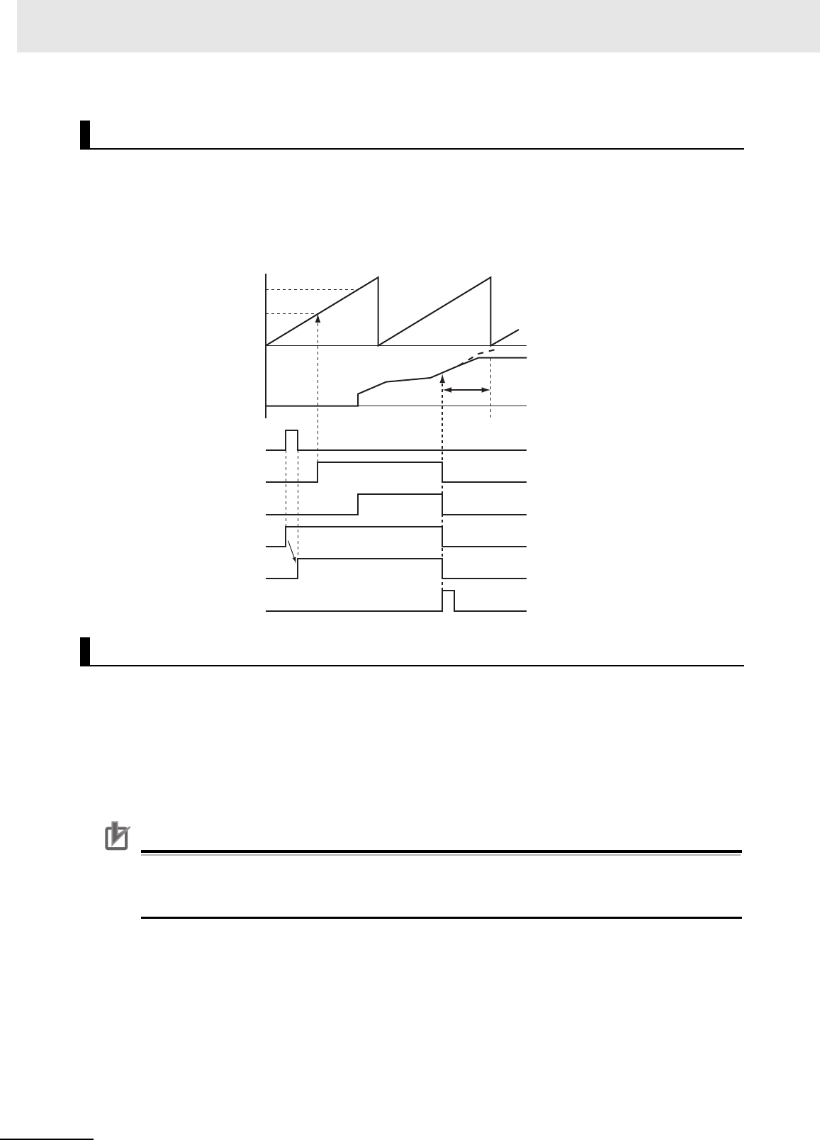
3 Axis Command Instructions
3-190
NJ/NX-series Motion Control Instructions Reference Manual (W508)
If an axis error occurs for the slave axis during execution of this instruction, the slave axis decelerates
to a stop at the maximum deceleration rate for the axis. If the MC_Stop instruction is executed for the
slave axis, CommandAborted changes to TRUE and the slave axis decelerates to a stop at the deceler-
ation rate that is specified in the MC_Stop instruction. Refer to A-1 Error Codes for information on isolat-
ing the causes of axis errors. If an axis error occurs on the master axis, cam operation will continue.
You can re-execute this instruction to change the cam table during operation. To change any conditions
other than the cam table, use multi-execution of instructions for this instruction.
When re-executing the instruction, InCam and InSync retain the status that they had prior to the re-exe-
cution. If the instruction is re-executed when InSync is TRUE, the cam operation starts from the phase
that is larger than the phase for the actual position. The phase for the actual position is found by linearly
interpolating between cam data points.
Only the cam table is affected by re-execution.
Precautions for Correct UsePrecautions for Correct Use
If a cam table is switched by re-executing the instruction during a cam motion, the velocity or
acceleration of the slave axis may change rapidly after re-execution. Be careful when re-execut-
ing the instruction because the mechanical composition may be affected.
For details on re-execution of motion control instructions, refer to the NJ/NX-series CPU Unit Motion
Control User’s Manual (Cat. No. W507) or NY-series Industrial Panel PC / Industrial Box PC Motion
Control User’s Manual (Cat. No. W559).
Aborting the Instruction
Re-execution of Motion Control Instructions
Deceleration
stopping
Slave axis position
Master axis position
Execute
Busy
Active
InCam
InSync
CommandAborted
MasterStartDistance
StartPosition

3 Axis Command Instructions
3-191
NJ/NX-series Motion Control Instructions Reference Manual (W508)
MC_CamIn
3
Function
Re-execution Procedure
For the procedure to re-execute this instruction, refer to Sample Programming 1 on page 3-192 and
Sample Programming 2 on page 3-203.
For details on multi-execution of motion control instructions, refer to the NJ/NX-series CPU Unit Motion
Control User’s Manual (Cat. No. W507) or NY-series Industrial Panel PC / Industrial Box PC Motion
Control User’s Manual (Cat. No. W559).
Execution of Other Instructions during Instruction Execution
Multi-execution of instructions cannot be used for the MC_GenerateCamTable (Generate Cam
Table) instruction during execution of an MC_CamIn instruction for which the same cam table is
specified with CamTable.
To use multi-execution of motion instructions for this instruction, specify the slave axis. When multi-
execution of another instruction is performed while this instruction is in execution, the following limits
apply depending on the Buffer Mode.
• When another instruction is executed by using multi-execution with BufferMode set to Aborting,
the cam motion is aborted and the next operation is started.
• When another instruction is executed with BufferMode set to Buffered, the command position of
the next operation is output when EndOfProfile (End of Cam Cycle) changes to TRUE.
Multi-execution of MC_CamIn Instructions with Buffer Mode in Blending
• You can specify blending only for multi-execution of two MC_CamIn instructions. You cannot exe-
cute this instruction with blending during execution of any other instruction.
• Specify the same values for Master (Master Axis) and ReferenceType (Position Type Selection) as
those specified in the instruction that is currently in operation. If you specify different values, a
Motion Control Instruction Multi-execution Disabled error will occur.
• The InSync output variable from the buffered instruction changes to TRUE in the period in which
the current instruction is completed normally, and cam operation starts without the slave axis ever
stopping.
• Even if StartPosition (Cam Table Start Position) and MasterStartDistance (Master Following Dis-
tance) are specified, the slave axis starts cam operation as soon as instruction execution starts
regardless of the values that are specified. The starting point in the cam table is the final position
for the current instruction. The operation is the same regardless of which of the four types of
blending is specified.
Execution during Execution of Other Instructions
Multi-execution of instructions cannot be used for this instruction during execution of the MC_Gener-
ateCamTable (Generate Cam Table) instruction for which the same cam table is specified with Cam-
Ta bl e.
Master Axis and Slave Axis Compensations
There are the following two instructions that shift the phase of master and slave axes during syn-
chronized control.
• MC_Phasing (Shift Master Axis Phase)
• MC_SyncOffsetPosition (Cyclic Synchronous Position Offset Compensation)
If multi-execution of instructions causes any synchronized control instruction other than the MC_-
CamIn (Start Cam Operation) instruction to be aborted (i.e., if the CommandAborted output variable
changes to TRUE), any instructions that shift the phase are also aborted.
If blending is used for multi-execution of two MC_CamIn (Start Cam Operation) instructions, the
instructions that shift the phase are not aborted and processing is continued.
Multi-execution of Motion Control Instructions

3 Axis Command Instructions
3-192
NJ/NX-series Motion Control Instructions Reference Manual (W508)
If an error occurs during instruction execution, Error will change to TRUE. You can find out the cause of
the error by referring to the value output by ErrorID (Error Code).
Timing Chart When Error Occurs
Error Codes
Refer to A-1 Error Codes for instruction errors.
This sample programming shows cam operation when periodic operation is specified. In this example,
the master axis is axis 1 and the slave axis is axis 2.
Additional Information
You can specify only the initial values for input variables that are reserved. In this sample, vari-
ables with initial values are defined for the instructions, but you do not need to assign variables
and parameters when you program them.
The minimum settings required for this sample programming are given below.
Setting Axis Parameters
Axis Types
Errors
Sample Programming 1
Parameter Settings
Axis Axis Type
Axis 1 Servo axis (master axis)
Axis 2 Servo axis (slave axis)
Error code
Slave axis position
Master axis position
Execute
Busy
Active
InCam
InSync
Error
ErrorID
16#0000

3 Axis Command Instructions
3-193
NJ/NX-series Motion Control Instructions Reference Manual (W508)
MC_CamIn
3
Sample Programming 1
Count Modes
Ring Counter
Units of Display
Operation Pattern
1
Starting Cam Operation
If the cam table start point position (zero phase position) is 20°, the slave axis starts operation
when the master axis reaches a position where the relative angle from that point is 40°. Cam
operation operates in a periodic motion. If Periodic is TRUE, periodic operation is performed.
2
Ending Cam Operation
When the actual position of the slave axis MC_Axis001.Act.Pos exceeds 1000.0, cam operation
is ended and the slave axis is stopped at deceleration rate DecRate2.
Axis Count Mode
Axis 1 Rotary Mode
Axis 2 Linear Mode
Axis
Modulo maxi-
mum position
Modulo mini-
mum position
Axis 1 360 0
Axis Unit of Display
Axis 1 degree
Axis 2 mm
Operation Example
1000
0
360°
60°
20°
MC_CamOut executed.
Time
Time
Slave axis command position
Master axis command position
Cam operation start point 40°
(relative)
Cam table start position

3 Axis Command Instructions
3-194
NJ/NX-series Motion Control Instructions Reference Manual (W508)
Main Variables
Ladder Diagram
Name Data type Default Comment
MC_Axis000 _sAXIS_REF --- Axis Variable for the master axis, axis 1.
MC_Axis000.MFaultLvl.Active BOOL FALSE TRUE while there is a minor fault level
error for axis 1.
MC_Axis000.Details.Homed BOOL FALSE TRUE when home is defined for axis 1.
MC_Axis001 _sAXIS_REF --- Axis Variable for the slave axis, axis 2.
MC_Axis001.MFaultLvl.Active BOOL FALSE TRUE while there is a minor fault level
error for axis 2.
MC_Axis001.Details.Homed BOOL FALSE TRUE when home is defined for axis 2.
Pwr1_S BOOL FALSE This variable is assigned to the Status
output variable from the PWR1 instance
of the MC_Power instruction. This vari-
able changes to TRUE when the Servo
is turned ON.
Pwr2_S BOOL FALSE This variable is assigned to the Status
output variable from the PWR2 instance
of the MC_Power instruction. This vari-
able changes to TRUE when the Servo
is turned ON.
CamProfile0 ARRAY[0..360] OF
_sMC_CAM_REF
--- This is the cam data variable. The array
elements ARRAY[0..N] are set with the
Cam Editor. In this sample, 0 to 360 are
used, but the number of array elements
depends on the settings that you make
with the Cam Editor.
DecRate2 LREAL 10000.0 This variable sets the deceleration rate
for execution of MC_CamOut.
Vel_InVel BOOL FALSE This variable is assigned to the InVeloc-
ity output variable from the VEL instance
of the MC_MoveVelocity instruction. It is
TRUE when the target velocity is
reached.
Camin_InCam0 BOOL FALSE This variable is assigned to the InCam
output variable from the CAMIN instance
of the MC_CamIn instruction. It is TRUE
during cam operation.
Camout_Ex BOOL FALSE The CAMOUT instance of MC_CamOut
is executed while this variable is TRUE.
StartPg BOOL FALSE The Servo is turned ON if this variable is
TRUE and EtherCAT process data com-
munications are established.

3 Axis Command Instructions
3-195
NJ/NX-series Motion Control Instructions Reference Manual (W508)
MC_CamIn
3
Sample Programming 1
Timing Chart
Sample Programming
Master axis
Slave axis
MC_CamIn Instruction
MC_CamOut Instruction
MC_MoveVelocity Instruction
Camin_InCam0
Camin_InSync
Camin_EOP
MC_Axis000.Cmd.Pos
MC_Axis001.Cmd.Pos
Camin_Index
Camin_Bsy
Camin_Act
Camin_Ca
Camout_Ex
Camout_Bsy
Camout_D
Vel_InVel
StartPg
Lock1
MC_Axis000.DrvStatus.Ready
StartPg
Lock2
MC_Axis001.DrvStatus.Ready
PWR1
Error
Axis Axis
Enable Status
Busy
MC_Power
ErrorID
Lock1
MC_Axis000
Pwr1_S
Pwr1_Bsy
Pwr1_Err
Pwr1_ErrID
If the Servo Drive for axis 1 is ready, the Servo is turned ON.
If StartPg is TRUE, check that the Servo Drive for axis 1 is ready.
If StartPg is TRUE, check that the Servo Drive for axis 2 is ready.
3 Axis Command Instructions
3-196
NJ/NX-series Motion Control Instructions Reference Manual (W508)
HM1
Axis Axis
Execute
Error
ErrorID
CommandAborted
MC_Home
Done
Busy
MC_Axis000
Pwr1_S
Hm1_D
Hm1_Bsy
Hm1_Ca
Hm1_Err
Hm1_ErrID
PWR2
Error
Axis Axis
Enable Status
Busy
MC_Power
ErrorID
Lock2
MC_Axis001
Pwr2_S
Pwr2_Bsy
Pwr2_Err
Pwr2_ErrID
FaultHandlerMC_Axis000.MFaultLvl.Active
FaultHandlerEN
MC_Axis001.MFaultLvl.Active
HM2
Axis Axis
Execute
Error
ErrorID
CommandAborted
MC_Home
Done
Busy
MC_Axis001
Pwr2_S
Hm2_D
Hm2_Bsy
Hm2_Ca
Hm2_Err
Hm2_ErrID
MC_Axis000
Hm1_D
Vel_InVel
BufferMode
VEL
Jerk
Active
Axis Axis
Execute InVelocity
Velocity Busy
Deceleration
Error
Direction
Continuous
MC_MoveVelocity
Acceleration
CommandAborted
ErrorID_eMC_DIRECTION#_mcPositiveDirection
LREAL#1000.0
LREAL#100000.0
Vel_Bsy
Vel_Act
Vel_Ca
Vel_Err
Vel_EIrrD
LREAL#100000.0
MC_Axis000.Details.Homed
MC_Axis001.Details.Homed
If the Servo is ON for axis 1 and home is not defined, the Home instruction is executed to define home.
If the Servo Drive for axis 2 is ready, the Servo is turned ON.
If a minor fault level error occurs for the axis composition, the error handler for the device (FaultHandler) is executed.
Program the FaultHandler according to the device.
If the Servo is ON for axis 2 and home is not defined, the Home instruction is executed to define home.
The MC_MoveVelocity (Velocity Control) instruction is executed after homing is completed for axis 1.

3 Axis Command Instructions
3-197
NJ/NX-series Motion Control Instructions Reference Manual (W508)
MC_CamIn
3
Sample Programming 1
Contents of Inline ST
IF MC_Axis001.Act.Pos>LREAL#1000.0 THEN
Camout_Ex := TRUE;
END_IF;
Main Variables
Structured Text (ST)
Name Data type Default Comment
MC_Axis000 _sAXIS_REF -- Axis Variable for the master axis, axis 1.
MC_Axis000.MFaultLvl.Active BOOL FALSE TRUE while there is a minor fault level
error for axis 1.
MC_Axis000.Details.Homed BOOL FALSE TRUE when home is defined for axis 1.
MC_Axis001 _sAXIS_REF --- Axis Variable for the slave axis, axis 2.
MC_Axis001.MFaultLvl.Active BOOL FALSE TRUE while there is a minor fault level
error for axis 2.
MC_Axis001 Camout_D
DecRate2 Camout_Bsy
Camout_Ca
Camout_Err
Camout_ErrID
CAMOUT
Slave
Execute
Slave
Deceleration
OutMode Error
ErrorID
CommandAborted
MC_CamOut
Jerk
Done
Busy
MasterScaling
SlaveScaling
MasterOffset
SlaveOffset
ReferenceType
CAMIN
StartMode
InCam
Master Master
Slave Slave
CamTable CamTable
Periodic
EndOfProfile
CommandAborted
Error
Active
StartPosition
BusyMasterStartDistance
MC_CamIn
Execute
InSync
Index
Direction
BufferMode
CamTransition
ErrorID
MC_Axis000
MC_Axis001
CamProfile0
Vel_InVel
_eMC_DIRECTION#_mcNoDirection
_eMC_REFERENCE_TYPE#_mcCommand
_eMC_START_MODE#_mcRelativePosition
BOOL#TRUE
LREAL#20.0
LREAL#40.0
LREAL#1.0
LREAL#1.0
LREAL#0.0
LREAL#0.0
Camin_InCam0
Camin_Bsy
Camin_Act
Camin_Ca
Camin_Err
Camin_ErrID
Camin_InSync
Camin_EOP
Camin_Index
Camin_InCam0
Camout_Ex
The MC_CamOut (End Cam Operation) instruction is executed when Camout_Ex changes to TRUE.
The deceleration rate is specified by DecRate2.
CamOut_Ex changes to TRUE if Camin_InCam0 is TRUE and MC_Axis001.Act.Pos exceeds 1000.
The MC_CamIn (Start Cam Operation) instruction is executed if Vel_InVel is TRUE for the MC_MoveVelocity
(Velocity Control) instruction.
Note: The contents of the inline
ST are given below.

3 Axis Command Instructions
3-198
NJ/NX-series Motion Control Instructions Reference Manual (W508)
MC_Axis001.Details.Homed BOOL FALSE TRUE when home is defined for axis 2.
Pwr1_S BOOL FALSE This variable is assigned to the Status
output variable from the PWR1 instance
of the MC_Power instruction. This vari-
able changes to TRUE when the Servo
is turned ON.
Pwr2_S BOOL FALSE This variable is assigned to the Status
output variable from the PWR2 instance
of the MC_Power instruction. This vari-
able changes to TRUE when the Servo
is turned ON.
CamProfile0 ARRAY[0..360] OF
_sMC_CAM_REF
--- This is the cam data variable. The array
elements ARRAY[0..N] are set with the
Cam Editor. In this sample, 0 to 360 are
used, but the number of array elements
depends on the settings that you make
with the Cam Editor.
DecRate2 LREAL 10000.0 This variable sets the deceleration rate
for execution of MC_CamOut.
Vel_InVel BOOL FALSE This variable is assigned to the InVeloc-
ity output variable from the VEL instance
of the MC_MoveVelocity instruction. It is
TRUE when the target velocity is
reached.
Camin_InCam0 BOOL FALSE This variable is assigned to the InCam
output variable from the CAMIN instance
of the MC_CamIn instruction. It is TRUE
during cam operation.
Camout_Ex BOOL FALSE The CAMOUT instance of MC_CamOut
is executed while this variable is TRUE.
StartPg BOOL FALSE The Servo is turned ON if this variable is
TRUE and EtherCAT process data com-
munications are established.
Camin_Ex BOOL FALSE This variable is changed to TRUE when
Vel_InVel changes to TRUE to change
Execute for the CAMIN instance of MC_-
CamIn to TRUE.
InitFlag BOOL FALSE This variable indicates if it is necessary
to set the input parameters. Input param-
eters are set when this variable is
FALSE. When setting the input parame-
ters is completed, this variable changes
to TRUE.
Name Data type Default Comment

3 Axis Command Instructions
3-199
NJ/NX-series Motion Control Instructions Reference Manual (W508)
MC_CamIn
3
Sample Programming 1
Timing Chart
Sample Programming
// Processing when input parameters are not set
IF InitFlag=FALSE THEN
// MC_CamIn parameters
Camin_EM := TRUE; // Periodic Mode
Camin_StMode := _eMC_START_MODE#_mcRelativePosition;
Camin_StPos := LREAL#20.0; // Master axis absolute position for start point
Camin_MStDis := LREAL#40.0; // Master axis position to start cam operation
Camin_MSc := LREAL#1.0; // Master axis scaling
Camin_SSc := LREAL#1.0; // Slave axis scaling
Camin_MO := LREAL#0.0; // Master offset
Camin_SO := LREAL#0.0; // Slave offset
Camin_RT := _eMC_REFERENCE_TYPE#_mcCommand; // Position type selection
Camin_Dir := _eMC_DIRECTION#_mcNoDirection; // Direction
// MC_MoveVelocity parameters
Vel_Vel := LREAL#1000.0;
Vel_Acc := LREAL#100000.0;
Vel_Dec := LREAL#100000.0;
Vel_Dir := _eMC_DIRECTION#_mcPositiveDirection;
Camin_InCam0
Camin_Ex
Camin_InSync
Camin_EOP
MC_Axis000.Cmd.Pos
MC_Axis001.Cmd.Pos
Camin_Index
Camin_Bsy
Camin_Act
Camin_Ca
Camout_Ex
Camout_Bsy
Camout_D
Vel_InVel
Master axis
Slave axis
MC_CamIn Instruction
MC_CamOut Instruction
MC_MoveVelocity Instruction

3 Axis Command Instructions
3-200
NJ/NX-series Motion Control Instructions Reference Manual (W508)
// MC_CamOut parameters
Camout_Dec := DecRate2;
// Change InitFlag to TRUE after setting the input parameters.
InitFlag := TRUE;
END_IF;
// If StartPg is TRUE and the Servo Drive is ready, the Servo for axis 1 is turned ON.
// If the Servo Drive is not ready, the Servo is turned OFF.
IF (StartPg=TRUE)
AND (MC_Axis000.DrvStatus.Ready=TRUE) THEN
Pwr1_En:=TRUE;
ELSE
Pwr1_En:=FALSE;
END_IF;
// If StartPg is TRUE and the Servo Drive is ready, the Servo for axis 2 is turned ON.
// If the Servo Drive is not ready, the Servo is turned OFF.
IF (StartPg=TRUE)
AND (MC_Axis001.DrvStatus.Ready=TRUE) THEN
Pwr2_En:=TRUE;
ELSE
Pwr2_En:=FALSE;
END_IF;
// If a minor fault level error occurs for axis 1 or axis 2, the error handler for the device is executed.
// Program the FaultHandler according to the device.
IF (MC_Axis000.MFaultLvl.Active=TRUE) OR (MC_Axis001.MFaultLvl.Active=TRUE) THEN
FaultHandler();
END_IF;
// If the Servo is ON for axis 1 and home is not defined, the Home instruction is executed for axis 1.
IF (Pwr1_S=TRUE) AND (MC_Axis000.Details.Homed=FALSE) THEN
Hm1_Ex:=TRUE;
END_IF;
// If the Servo is ON for axis 2 and home is not defined, the Home instruction is executed for axis 2.
IF (Pwr2_S=TRUE) AND (MC_Axis001.Details.Homed=FALSE) THEN
Hm2_Ex:=TRUE;
END_IF;
// After homing is completed for axis 1, MC_MoveVelocity is executed.
IF Hm1_D=TRUE THEN
Vel_Ex := TRUE;
END_IF;
// CamIn is executed when InVel of MC_MoveVelocity is TRUE.
IF Vel_InVel=TRUE THEN
Camin_Ex := TRUE;
END_IF;
// CamOut is executed when Camin_InCam0 is TRUE and MC_Axis001.Act.Pos is greater than 1000.
IF (Camin_InCam0=TRUE) AND (MC_Axis001.Act.Pos>LREAL#1000.0) THEN
Camout_Ex := TRUE;
END_IF;
// MC_Power for axis 1
PWR1(
Axis := MC_Axis000,
Enable := Pwr1_En,
Status => Pwr1_S,
Busy => Pwr1_Bsy,

3 Axis Command Instructions
3-201
NJ/NX-series Motion Control Instructions Reference Manual (W508)
MC_CamIn
3
Sample Programming 1
Error => Pwr1_Err,
ErrorID => Pwr1_ErrID
);
// MC_Power for axis 2
PWR2(
Axis := MC_Axis001,
Enable := Pwr2_En,
Status => Pwr2_S,
Busy => Pwr2_Bsy,
Error => Pwr2_Err,
ErrorID => Pwr2_ErrID
);
// MC_Home for axis 1
HM1(
Axis := MC_Axis000,
Execute := Hm1_Ex,
Done => Hm1_D,
Busy => Hm1_Bsy,
CommandAborted => Hm1_Ca,
Error => Hm1_Err,
ErrorID => Hm1_ErrID
);
// MC_Home for axis 2
HM2(
Axis := MC_Axis001,
Execute := Hm2_Ex,
Done => Hm2_D,
Busy => Hm2_Bsy,
CommandAborted => Hm2_Ca,
Error => Hm2_Err,
ErrorID => Hm2_ErrID
);
//MC_MoveVelocity
VEL(
Axis := MC_Axis000,
Execute := Vel_Ex,
Velocity := Vel_Vel,
Acceleration := Vel_Acc,
Deceleration := Vel_Dec,
Direction := Vel_Dir,
InVelocity => Vel_InVel,
Busy => Vel_Bsy,
Active => Vel_Act,
CommandAborted => Vel_Ca,
Error => Vel_Err,
ErrorID => Vel_ErrID
);
//MC_CamIn
CAMIN(
Master := MC_Axis000,
Slave := MC_Axis001,
CamTable := CamProfile0,
Execute := Camin_Ex,
Periodic := Camin_EM,
StartMode := Camin_StMode,
StartPosition := Camin_StPos,

3 Axis Command Instructions
3-202
NJ/NX-series Motion Control Instructions Reference Manual (W508)
MasterStartDistance := Camin_MStDis,
MasterScaling := Camin_MSc,
SlaveScaling := Camin_SSc,
MasterOffset := Camin_MO,
SlaveOffset := Camin_SO,
ReferenceType := Camin_RT,
Direction := Camin_Dir,
CamTransition := Camin_CT,
BufferMode := Camin_BM,
InCam => Camin_InCam0,
InSync => Camin_InSync,
EndOfProfile => Camin_EOP,
Index => Camin_Index,
Busy => Camin_Bsy,
Active => Camin_Act,
CommandAborted => Camin_Ca,
Error => Camin_Err,
ErrorID => Camin_ErrID
);
//MC_CamOut
CAMOUT(
Slave := MC_Axis001,
Execute := Camout_Ex,
Deceleration := Camout_Dec,
Done => Camout_D,
Busy => Camout_Bsy,
CommandAborted => Camout_Ca,
Error => Camout_Err,
ErrorID => Camout_ErrID
);

3 Axis Command Instructions
3-203
NJ/NX-series Motion Control Instructions Reference Manual (W508)
MC_CamIn
3
Sample Programming 2
This sample programming shows cam operation for a liquid filler.
Additional Information
You can specify only the initial values for input variables that are reserved. Parameters are not
specified in this sample.
The minimum settings required for this sample programming are given below.
Setting Axis Parameters
Axis Types
Count Modes
Ring Counters
Units of Display
Sample Programming 2
Parameter Settings
Axis Axis Type
Axis 1 Servo axis (master axis)
Axis 2 Servo axis (slave axis)
Axis 3 Servo axis (slave axis)
Axis 4 Servo axis (slave axis)
Axis 5 Servo axis (slave axis)
Axis Count Mode
Axis 1 Rotary Mode
Axis 2 Rotary Mode
Axis 3 Rotary Mode
Axis 4 Rotary Mode
Axis 5 Rotary Mode
Axis
Modulo maxi-
mum position
Modulo mini-
mum position
Axis 1 360 0
Axis 2 360 0
Axis 3 360 0
Axis 4 360 0
Axis 5 360 0
Axis Unit of Display
Axis 1 degree
Axis 2 degree
Axis 3 degree
Axis 4 degree
Axis 5 degree
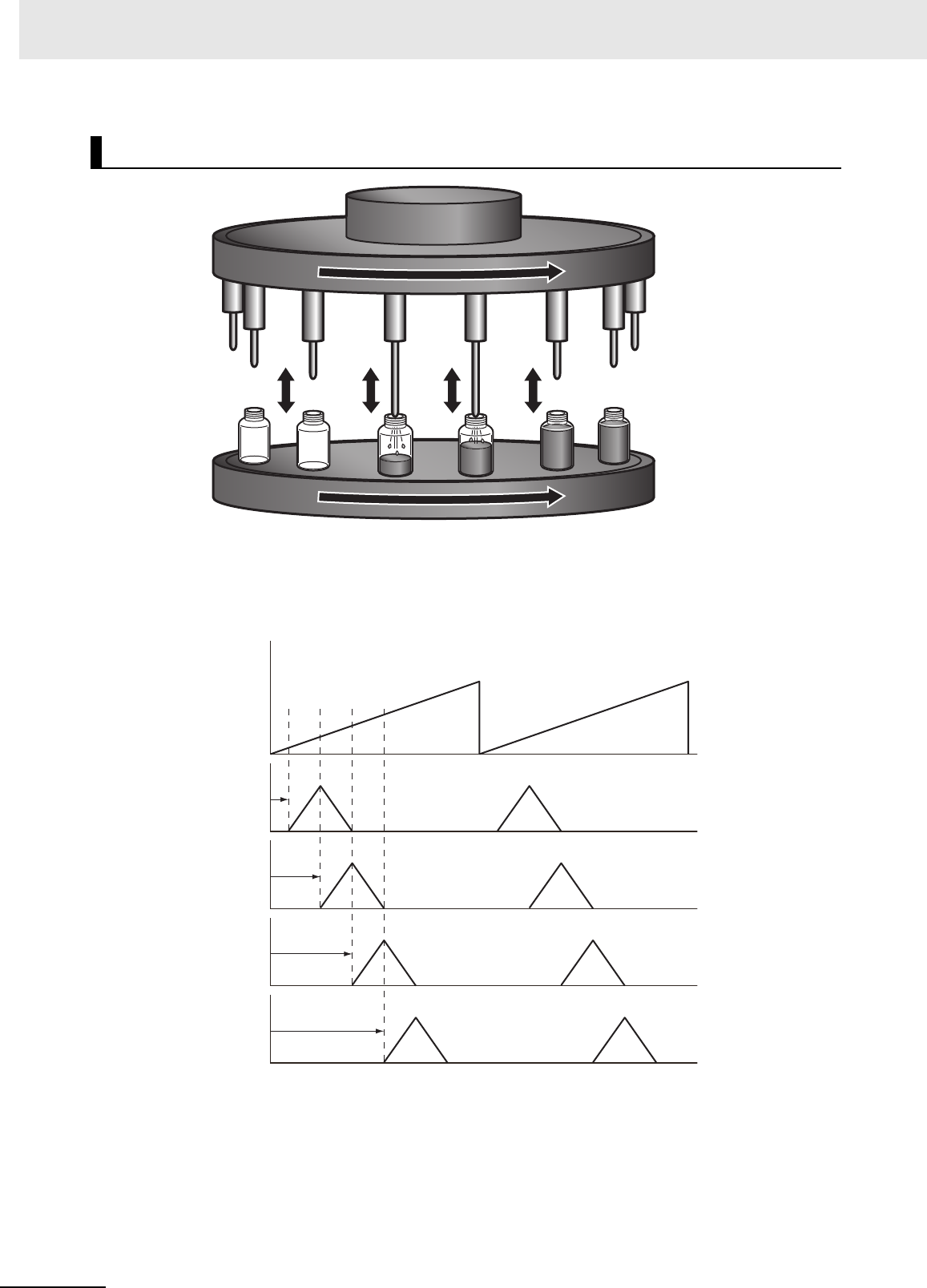
3 Axis Command Instructions
3-204
NJ/NX-series Motion Control Instructions Reference Manual (W508)
Operation Pattern
1
Start Cam Operation
The slave axes, axes 2 to 5, perform cam operation in synchronization with the master axis, axis
1. Each axis shifts its phase by 50° and starts cam operation.
2
Periodic Operation
Each axis periodically executes the specified cam operation.
Operation Example
Synchronized master axis
Synchronized slave axis
Axis 1
Axis 2 Axis 3 Axis 4 Axis 5
MasterOffset = 130
MasterOffset = 180
MasterOffset = 30
MasterOffset = 80
Axis 1
Axis 2
Axis 3
Axis 4
Axis 5

3 Axis Command Instructions
3-205
NJ/NX-series Motion Control Instructions Reference Manual (W508)
MC_CamIn
3
Sample Programming 2
Main Variables
Timing Chart
*1 The timing is the same for the following: Camin1_InCam, Camin2_InCam, Camin3_InCam, and Camin4_In-
Cam.
Ladder Diagram
Name Data type Default Comment
MC_Axis000 _sAXIS_REF --- Axis Variable for the master axis, axis 1.
MC_Axis001 _sAXIS_REF --- Axis Variable for the slave axis, axis 2.
MC_Axis002 _sAXIS_REF --- Axis Variable for the slave axis, axis 3.
MC_Axis003 _sAXIS_REF --- Axis Variable for the slave axis, axis 4.
MC_Axis004 _sAXIS_REF --- Axis Variable for the slave axis, axis 5.
StartPg BOOL FALSE The Servo is turned ON if this variable is TRUE and Eth-
erCAT process data communications are established.
Vel_InVel BOOL FALSE This variable is assigned to the InVelocity output vari-
able from the VEL instance of the MC_MoveVelocity
instruction. It is TRUE when the target velocity is
reached.
CamProfile0 ARRAY[0..360] OF
_sMC_CAM_REF
--- This is the cam data variable. This variable is assigned
to the CamTable input variables from the CAMIN1 to
CAMIN4 instances of the MC_CamIn instruction. The
array elements ARRAY[0..N] are set with the Cam Edi-
tor.
MC_Axis000.Cmd.Pos
MC_Axis001.Cmd.Pos
MC_Axis002.Cmd.Pos
MC_Axis003.Cmd.Pos
MC_Axis004.Cmd.Pos
Camin1_Eop
Camin2_Eop
Camin3_Eop
Camin4_Eop
InCam
*1
InSync
*2
Busy
*3
Active
*4
Vel_InVel
Axis 1
Axis 2
Axis 3
Axis 4
Axis 5
MC_CamIn Instruction
MC_MoveVelocity Instruction

3 Axis Command Instructions
3-206
NJ/NX-series Motion Control Instructions Reference Manual (W508)
*2 The timing is the same for the following: Camin1_InSync, Camin2_InSync, Camin3_InSync, and Camin4_In-
Sync. In this sample, MasterStartDistance is 0, so InSync changes to TRUE from when the master axis is 0°.
*3 The timing is the same for the following: Camin1_Bsy, Camin2_Bsy, Camin3_Bsy, and Camin4_Bsy.
*4 The timing is the same for the following: Camin1_Act, Camin2_Act, Camin3_Act, and Camin4_Act.

3 Axis Command Instructions
3-207
NJ/NX-series Motion Control Instructions Reference Manual (W508)
MC_CamIn
3
Sample Programming 2
Sample Programming
PWR1
Error
Axis Axis
Enable Status
Busy
MC_Power
ErrorID
Lock1
MC_Axis000
Pwr1_Status
Pwr1_Bsy
Pwr1_Err
Pwr1_ErrID
PWR2
Error
Axis Axis
Enable Status
Busy
MC_Power
ErrorID
Lock2
MC_Axis001
Pwr2_Status
Pwr2_Bsy
Pwr2_Err
Pwr2_ErrID
PWR3
Error
Axis Axis
Enable Status
Busy
MC_Power
ErrorID
Lock3
MC_Axis002
Pwr3_Status
Pwr3_Bsy
Pwr3_Err
Pwr3_ErrID
PWR4
Error
Axis Axis
Enable Status
Busy
MC_Power
ErrorID
Lock4
MC_Axis003
Pwr4_Status
Pwr4_Bsy
Pwr4_Err
Pwr4_ErrID
StartPg
Lock1
MC_Axis000.DrvStatus.Ready
StartPg
Lock2
MC_Axis001.DrvStatus.Ready
StartPg
Lock3
MC_Axis002.DrvStatus.Ready
StartPg
Lock4
MC_Axis003.DrvStatus.Ready
StartPg
Lock5
MC_Axis004.DrvStatus.Ready
If StartPg is TRUE, check that the Servo Drives for each axis are ready.
If the Servo Drives are ready, the Servos are turned ON for each axis.

3 Axis Command Instructions
3-208
NJ/NX-series Motion Control Instructions Reference Manual (W508)
HM1
Axis Axis
Execute
Error
ErrorID
CommandAborted
MC_Home
Done
Busy
MC_Axis000
Pwr1_Status
Hm1_D
Hm1_Bsy
Hm1_Ca
Hm1_Err
Hm1_ErrID
HM3
Axis Axis
Execute
Error
ErrorID
CommandAborted
MC_Home
Done
Busy
MC_Axis002
Pwr3_Status
Hm3_D
Hm3_Bsy
Hm3_Ca
Hm3_Err
Hm3_ErrID
PWR5
Error
Axis Axis
Enable Status
Busy
MC_Power
ErrorID
Lock5
MC_Axis004
Pwr5_Status
Pwr5_Bsy
Pwr5_Err
Pwr5_ErrID
FaultHandlerMC_Axis000.MFaultLvl.Active
FaultHandlerEN
MC_Axis001.MFaultLvl.Active
MC_Axis002.MFaultLvl.Active
MC_Axis003.MFaultLvl.Active
MC_Axis004.MFaultLvl.Active
HM2
Axis Axis
Execute
Error
ErrorID
CommandAborted
MC_Home
Done
Busy
MC_Axis001
Pwr2_Status
Hm2_D
Hm2_Bsy
Hm2_Ca
Hm2_Err
Hm2_ErrID
MC_Axis000.Details.Homed
MC_Axis001.Details.Homed
MC_Axis002.Details.Homed
If the Servo is ON for axis 1 to axis 5 and the Home instruction is executed for each axis if home is not defined.
If a minor fault level error occurs for the axis composition, the error handler for the device (FaultHandler) is executed.
Program the FaultHandler according to the device.

3 Axis Command Instructions
3-209
NJ/NX-series Motion Control Instructions Reference Manual (W508)
MC_CamIn
3
Sample Programming 2
MC_Axis000
Hm1_D
Vel_InVel
BufferMode
VEL
Jerk
Active
Axis Axis
Execute InVelocity
Velocity Busy
Deceleration
Error
Direction
Continuous
MC_MoveVelocity
Acceleration
CommandAborted
ErrorID_eMC_DIRECTION#_mcPositiveDirection
LREAL#1000.0
LREAL#0.0
Vel_Bsy
Vel_Act
Vel_Ca
Vel_Err
Vel_ErrID
LREAL#0.0
MasterScaling
SlaveScaling
MasterOffset
SlaveOffset
ReferenceType
CAMIN1
StartMode
InCam
Master Master
Slave Slave
CamTable CamTable
Periodic
EndOfProfile
CommandAborted
Error
Active
StartPosition
BusyMasterStartDistance
MC_CamIn
Execute
InSync
Index
Direction
BufferMode
CamTransition
ErrorID
MC_Axis000
MC_Axis001
CamProfile0
Vel_InVel MC_Axis001.Details.Homed
_eMC_DIRECTION#_mcNoDirection
_eMC_REFERENCE_TYPE#_mcCommand
_eMC_START_MODE#_mcAbsolutePosition
BOOL#FALSE
LREAL#0.0
LREAL#0.0
LREAL#1.0
LREAL#1.0
LREAL#30.0
LREAL#0.0
Camin1_InCam
Camin1_Bsy
Camin1_Act
Camin1_Ca
Camin1_Err
Camin1_ErrID
Camin1_InSync
Camin1_Eop
Camin1_Index
HM4
Axis Axis
Execute
Error
ErrorID
CommandAborted
MC_Home
Done
Busy
MC_Axis003
Pwr4_Status
Hm4_D
Hm4_Bsy
Hm4_Ca
Hm4_Err
Hm4_ErrID
HM5
Axis Axis
Execute
Error
ErrorID
CommandAborted
MC_Home
Done
Busy
MC_Axis004
Pwr5_Status
Hm5_D
Hm5_Bsy
Hm5_Ca
Hm5_Err
Hm5_ErrID
MC_Axis003.Details.Homed
MC_Axis004.Details.Homed
The MC_MoveVelocity (Velocity Control) instruction is executed after homing is completed for axis 1.
The MC_CamIn (Start Cam Operation) instruction is executed for axis 2 (slave axis) if Vel_InVel is TRUE for the
MC_MoveVelocity (Velocity Control) instruction and homing is completed for axis 2.

3 Axis Command Instructions
3-210
NJ/NX-series Motion Control Instructions Reference Manual (W508)
MasterScaling
SlaveScaling
MasterOffset
SlaveOffset
ReferenceType
CAMIN2
StartMode
InCam
Master Master
Slave Slave
CamTable CamTable
Periodic
EndOfProfile
CommandAborted
Error
Active
StartPosition
BusyMasterStartDistance
MC_CamIn
Execute
InSync
Index
Direction
BufferMode
CamTransition
ErrorID
MC_Axis000
MC_Axis002
CamProfile0
Vel_InVel MC_Axis002.Details.Homed
_eMC_DIRECTION#_mcNoDirection
_eMC_REFERENCE_TYPE#_mcCommand
_eMC_START_MODE#_mcAbsolutePosition
BOOL#FALSE
LREAL#0.0
LREAL#0.0
LREAL#1.0
LREAL#1.0
LREAL#80.0
LREAL#0.0
Camin2_InCam
Camin2_Bsy
Camin2_Act
Camin2_Ca
Camin2_Err
Camin2_ErrID
Camin2_InSync
Camin2_Eop
Camin2_Index
MasterScaling
SlaveScaling
MasterOffset
SlaveOffset
ReferenceType
CAMIN3
StartMode
InCam
Master Master
Slave Slave
CamTable CamTable
Periodic
EndOfProfile
CommandAborted
Error
Active
StartPosition
BusyMasterStartDistance
MC_CamIn
Execute
InSync
Index
Direction
BufferMode
CamTransition
ErrorID
MC_Axis000
MC_Axis003
CamProfile0
Vel_InVel MC_Axis003.Details.Homed
_eMC_DIRECTION#_mcNoDirection
_eMC_REFERENCE_TYPE#_mcCommand
_eMC_START_MODE#_mcAbsolutePosition
BOOL#FALSE
LREAL#0.0
LREAL#0.0
LREAL#1.0
LREAL#1.0
LREAL#130.0
LREAL#0.0
Camin3_InCam
Camin3_Bsy
Camin3_Act
Camin3_Ca
Camin3_Err
Camin3_ErrID
Camin3_InSync
Camin3_Eop
Camin3_Index
The MC_CamIn (Start Cam Operation) instruction is executed for axis 3 (slave axis) if Vel_InVel is TRUE for the
MC_MoveVelocity (Velocity Control) instruction and homing is completed for axis 3.
The MC_CamIn (Start Cam Operation) instruction is executed for axis 4 (slave axis) if Vel_InVel is TRUE for the
MC_MoveVelocity (Velocity Control) instruction and homing is completed for axis 4.

3 Axis Command Instructions
3-211
NJ/NX-series Motion Control Instructions Reference Manual (W508)
MC_CamIn
3
Sample Programming 2
Main Variables
Structured Text (ST)
Name Data type Default Comment
MC_Axis000 _sAXIS_REF --- Axis Variable for the master axis, axis 1.
MC_Axis001 _sAXIS_REF --- Axis Variable for the slave axis, axis 2.
MC_Axis002 _sAXIS_REF --- Axis Variable for the slave axis, axis 3.
MC_Axis003 _sAXIS_REF --- Axis Variable for the slave axis, axis 4.
MC_Axis004 _sAXIS_REF --- Axis Variable for the slave axis, axis 5.
StartPg BOOL FALSE The Servo is turned ON if this variable is TRUE and Eth-
erCAT process data communications are established.
Vel_InVel BOOL FALSE This variable is assigned to the InVelocity output vari-
able from the VEL instance of the MC_MoveVelocity
instruction. It is TRUE when the target velocity is
reached.
CamProfile0 ARRAY[0..360] OF
_sMC_CAM_REF
--- This is the cam data variable. This variable is assigned
to the CamTable input variables from the CAMIN1 to
CAMIN4 instances of the MC_CamIn instruction. The
array elements ARRAY[0..N] are set with the Cam Edi-
tor.
Camin1_Ex BOOL FALSE The CAMIN1 to CAMIN4 instances of MC_CamIn are
executed when this variable changes to TRUE.
Camin2_Ex BOOL FALSE
Camin3_Ex BOOL FALSE
Camin4_Ex BOOL FALSE
InitFlag BOOL FALSE This variable indicates if it is necessary to set the input
parameters. Input parameters are set when this variable
is FALSE. When setting the input parameters is com-
pleted, this variable changes to TRUE.
MasterScaling
SlaveScaling
MasterOffset
SlaveOffset
ReferenceType
CAMIN4
StartMode
InCam
Master Master
Slave Slave
CamTable CamTable
Periodic
EndOfProfile
CommandAborted
Error
Active
StartPosition
BusyMasterStartDistance
MC_CamIn
Execute
InSync
Index
Direction
BufferMode
CamTransition
ErrorID
MC_Axis000
MC_Axis004
CamProfile0
Vel_InVel MC_Axis004.Details.Homed
_eMC_DIRECTION#_mcNoDirection
_eMC_REFERENCE_TYPE#_mcCommand
_eMC_START_MODE#_mcAbsolutePosition
BOOL#FALSE
LREAL#0.0
LREAL#0.0
LREAL#1.0
LREAL#1.0
LREAL#180.0
LREAL#0.0
Camin4_InCam
Camin4_Bsy
Camin4_Act
Camin4_Ca
Camin4_Err
Camin4_ErrID
Camin4_InSync
Camin4_Eop
Camin4_Index
The MC_CamIn (Start Cam Operation) instruction is executed for axis 5 (slave axis) if Vel_InVel is TRUE for the
MC_MoveVelocity (Velocity Control) instruction and homing is completed for axis 5.

3 Axis Command Instructions
3-212
NJ/NX-series Motion Control Instructions Reference Manual (W508)
Timing Chart
*1 The timing is the same for the following: Camin1_InCam, Camin2_InCam, Camin3_InCam, and Camin4_In-
Cam.
*2 The timing is the same for the following: Camin1_InSync, Camin2_InSync, Camin3_InSync, and Camin4_In-
Sync. In this sample, MasterStartDistance is 0, so InSync changes to TRUE from when the master axis is 0°.
*3 The timing is the same for the following: Camin1_Bsy, Camin2_Bsy, Camin3_Bsy, and Camin4_Bsy.
*4 The timing is the same for the following: Camin1_Act, Camin2_Act, Camin3_Act, and Camin4_Act.
Sample Programming
// Processing when input parameters are not set
IF InitFlag=FALSE THEN
//MC_MoveVelocity Input Parameter
Vel_Vel := LREAL#1000.0;
Vel_Acc := LREAL#0.0;
Vel_Dec := LREAL#0.0;
Vel_Dir := _eMC_DIRECTION#_mcPositiveDirection;
//MC_CamIn Input Parameter
Camin1_Em := TRUE;
Camin1_Sm := _eMC_START_MODE#_mcAbsolutePosition;
Camin1_Sp := LREAL#0.0;
Camin1_Msd := LREAL#0.0;
Camin1_Ms := LREAL#1.0;
Camin1_Ss := LREAL#1.0;
MC_Axis000.Cmd.Pos
MC_Axis001.Cmd.Pos
MC_Axis002.Cmd.Pos
MC_Axis003.Cmd.Pos
MC_Axis004.Cmd.Pos
Camin1_Eop
Camin2_Eop
Camin3_Eop
Camin4_Eop
InCam
*2
Ex
*1
InSync
*3
Busy
*4
Active
*5
Vel_InVel
Master axis
Slave axis 1
Slave axis 2
Slave axis 3
Slave axis 4
MC_CamIn Instruction
MC_MoveVelocity Instruction

3 Axis Command Instructions
3-213
NJ/NX-series Motion Control Instructions Reference Manual (W508)
MC_CamIn
3
Sample Programming 2
Camin1_Mo := LREAL#30.0;
Camin1_So := LREAL#0.0;
Camin1_Rt := _eMC_REFERENCE_TYPE#_mcCommand;
Camin1_Dir := _eMC_DIRECTION#_mcNoDirection;
Camin2_Em := TRUE;
Camin2_Sm := _eMC_START_MODE#_mcAbsolutePosition;
Camin2_Sp := LREAL#0.0;
Camin2_Msd := LREAL#0.0;
Camin2_Ms := LREAL#1.0;
Camin2_Ss := LREAL#1.0;
Camin2_Mo := LREAL#80.0;
Camin2_So := LREAL#0.0;
Camin2_Rt := _eMC_REFERENCE_TYPE#_mcCommand;
Camin2_Dir := _eMC_DIRECTION#_mcNoDirection;
Camin3_Em := TRUE;
Camin3_Sm := _eMC_START_MODE#_mcAbsolutePosition;
Camin3_Sp := LREAL#0.0;
Camin3_Msd := LREAL#0.0;
Camin3_Ms := LREAL#1.0;
Camin3_Ss := LREAL#1.0;
Camin3_Mo := LREAL#130.0;
Camin3_So := LREAL#0.0;
Camin3_Rt := _eMC_REFERENCE_TYPE#_mcCommand;
Camin3_Dir := _eMC_DIRECTION#_mcNoDirection;
Camin4_Em := TRUE;
Camin4_Sm := _eMC_START_MODE#_mcAbsolutePosition;
Camin4_Sp := LREAL#0.0;
Camin4_Msd := LREAL#0.0;
Camin4_Ms := LREAL#1.0;
Camin4_Ss := LREAL#1.0;
Camin4_Mo := LREAL#180.0;
Camin4_So := LREAL#0.0;
Camin4_Rt := _eMC_REFERENCE_TYPE#_mcCommand;
Camin4_Dir := _eMC_DIRECTION#_mcNoDirection;
// Change InitFlag to TRUE after setting the input parameters.
InitFlag := TRUE;
END_IF;
// If StartPg is TRUE and the Servo Drive is ready, the Servo for axis 1 is turned ON.
// If the Servo Drive is not ready, the Servo is turned OFF.
IF (StartPg=TRUE)
AND (MC_Axis000.DrvStatus.Ready=TRUE) THEN
Pwr1_En:=TRUE;
ELSE
Pwr1_En:=FALSE;
END_IF;
// If StartPg is TRUE and the Servo Drive is ready, the Servo for axis 2 is turned ON.
// If the Servo Drive is not ready, the Servo is turned OFF.
IF (StartPg=TRUE)
AND (MC_Axis001.DrvStatus.Ready=TRUE) THEN
Pwr2_En:=TRUE;
ELSE
Pwr2_En:=FALSE;
END_IF;
// If StartPg is TRUE and the Servo Drive is ready, the Servo for axis 3 is turned ON.
// If the Servo Drive is not ready, the Servo is turned OFF.
IF (StartPg=TRUE)
AND (MC_Axis002.DrvStatus.Ready=TRUE) THEN

3 Axis Command Instructions
3-214
NJ/NX-series Motion Control Instructions Reference Manual (W508)
Pwr3_En:=TRUE;
ELSE
Pwr3_En:=FALSE;
END_IF;
// If StartPg is TRUE and the Servo Drive is ready, the Servo for axis 4 is turned ON.
// If the Servo Drive is not ready, the Servo is turned OFF.
IF (StartPg=TRUE)
AND (MC_Axis003.DrvStatus.Ready=TRUE) THEN
Pwr4_En:=TRUE;
ELSE
Pwr4_En:=FALSE;
END_IF;
// If StartPg is TRUE and the Servo Drive is ready, the Servo for axis 5 is turned ON.
// If the Servo Drive is not ready, the Servo is turned OFF.
IF (StartPg=TRUE)
AND (MC_Axis004.DrvStatus.Ready=TRUE) THEN
Pwr5_En:=TRUE;
ELSE
Pwr5_En:=FALSE;
END_IF;
// If a minor fault level error occurs for axis 1 to axis 5, the error handler for the device (FaultHandler) is
executed.
// Program the FaultHandler according to the device.
IF (MC_Axis000.MFaultLvl.Active=TRUE)
OR (MC_Axis001.MFaultLvl.Active=TRUE)
OR (MC_Axis002.MFaultLvl.Active=TRUE)
OR (MC_Axis003.MFaultLvl.Active=TRUE)
OR (MC_Axis004.MFaultLvl.Active=TRUE) THEN
FaultHandler();
END_IF;
// If the Servo is ON for axis 1 and home is not defined, the Home instruction is executed for axis 1.
IF (Pwr1_Status=TRUE) AND (MC_Axis000.Details.Homed=FALSE) THEN
Hm1_Ex:=TRUE;
END_IF;
// If the Servo is ON for axis 2 and home is not defined, the Home instruction is executed for axis 2.
IF (Pwr2_Status=TRUE) AND (MC_Axis001.Details.Homed=FALSE) THEN
Hm2_Ex:=TRUE;
END_IF;
// If the Servo is ON for axis 3 and home is not defined, the Home instruction is executed for axis 3.
IF (Pwr3_Status=TRUE) AND (MC_Axis002.Details.Homed=FALSE) THEN
Hm3_Ex:=TRUE;
END_IF;
// If the Servo is ON for axis 4 and home is not defined, the Home instruction is executed for axis 4.
IF (Pwr4_Status=TRUE) AND (MC_Axis003.Details.Homed=FALSE) THEN
Hm4_Ex:=TRUE;
END_IF;
// If the Servo is ON for axis 5 and home is not defined, the Home instruction is executed for axis 5.
IF (Pwr5_Status=TRUE) AND (MC_Axis004.Details.Homed=FALSE) THEN
Hm5_Ex:=TRUE;
END_IF;
// After homing is completed for axis 1, MC_MoveVelocity is executed.
IF Hm1_D=TRUE THEN
Vel_Ex:=TRUE;
END_IF;

3 Axis Command Instructions
3-215
NJ/NX-series Motion Control Instructions Reference Manual (W508)
MC_CamIn
3
Sample Programming 2
// If home is defined for axis 2 and Vel_InVel of MC_MoveVelocity is TRUE,
// the MC_CamIn instruction for axis 2 (slave axis) is executed.
IF (Vel_InVel=TRUE) AND (MC_Axis001.Details.Homed=TRUE) THEN
Camin1_Ex := TRUE;
END_IF;
// If home is defined for axis 3 and Vel_InVel of MC_MoveVelocity is TRUE,
// the MC_CamIn instruction for axis 3 (slave axis) is executed.
IF (Vel_InVel=TRUE) AND (MC_Axis002.Details.Homed=TRUE) THEN
Camin2_Ex := TRUE;
END_IF;
// If home is defined for axis 4 and Vel_InVel of MC_MoveVelocity is TRUE,
// the MC_CamIn instruction for axis 4 (slave axis) is executed.
IF (Vel_InVel=TRUE) AND (MC_Axis003.Details.Homed=TRUE) THEN
Camin3_Ex := TRUE;
END_IF;
// If home is defined for axis 5 and Vel_InVel of MC_MoveVelocity is TRUE,
// the MC_CamIn instruction for axis 5 (slave axis) is executed.
IF (Vel_InVel=TRUE) AND (MC_Axis004.Details.Homed=TRUE) THEN
Camin4_Ex := TRUE;
END_IF;
// MC_Power for axis 1
PWR1(
Axis := MC_Axis000,
Enable := Pwr1_En,
Status => Pwr1_Status,
Busy => Pwr1_Bsy,
Error => Pwr1_Err,
ErrorID => Pwr1_ErrID
);
// MC_Power for axis 2
PWR2(
Axis := MC_Axis001,
Enable := Pwr2_En,
Status => Pwr2_Status,
Busy => Pwr2_Bsy,
Error => Pwr2_Err,
ErrorID => Pwr2_ErrID
);
// MC_Power for axis 3
PWR3(
Axis := MC_Axis002,
Enable := Pwr3_En,
Status => Pwr3_Status,
Busy => Pwr3_Bsy,
Error => Pwr3_Err,
ErrorID => Pwr3_ErrID
);
// MC_Power for axis 4
PWR4(
Axis := MC_Axis003,
Enable := Pwr4_En,
Status => Pwr4_Status,
Busy => Pwr4_Bsy,
Error => Pwr4_Err,
ErrorID => Pwr4_ErrID
);
// MC_Power for axis 5

3 Axis Command Instructions
3-216
NJ/NX-series Motion Control Instructions Reference Manual (W508)
PWR5(
Axis := MC_Axis004,
Enable := Pwr5_En,
Status => Pwr5_Status,
Busy => Pwr5_Bsy,
Error => Pwr5_Err,
ErrorID => Pwr5_ErrID
);
// MC_Home for axis 1
HM1(
Axis := MC_Axis000,
Execute := Hm1_Ex,
Done => Hm1_D,
Busy => Hm1_Bsy,
CommandAborted => Hm1_Ca,
Error => Hm1_Err,
ErrorID => Hm1_ErrID
);
// MC_Home for axis 2
HM2(
Axis := MC_Axis001,
Execute := Hm2_Ex,
Done => Hm2_D,
Busy => Hm2_Bsy,
CommandAborted => Hm2_Ca,
Error => Hm2_Err,
ErrorID => Hm2_ErrID
);
// MC_Home for axis 3
HM3(
Axis := MC_Axis002,
Execute := Hm3_Ex,
Done => Hm3_D,
Busy => Hm3_Bsy,
CommandAborted => Hm3_Ca,
Error => Hm3_Err,
ErrorID => Hm3_ErrID
);
// MC_Home for axis 4
HM4(
Axis := MC_Axis003,
Execute := Hm4_Ex,
Done => Hm4_D,
Busy => Hm4_Bsy,
CommandAborted => Hm4_Ca,
Error => Hm4_Err,
ErrorID => Hm4_ErrID
);
// MC_Home for axis 5
HM5(
Axis := MC_Axis004,
Execute := Hm5_Ex,
Done => Hm5_D,
Busy => Hm5_Bsy,
CommandAborted => Hm5_Ca,
Error => Hm5_Err,
ErrorID => Hm5_ErrID
);
//MC_MoveVelocity

3 Axis Command Instructions
3-217
NJ/NX-series Motion Control Instructions Reference Manual (W508)
MC_CamIn
3
Sample Programming 2
VEL(
Axis := MC_Axis000,
Execute := Vel_Ex,
Velocity := Vel_Vel,
Acceleration := Vel_Acc,
Deceleration := Vel_Dec,
Direction := Vel_Dir,
InVelocity => Vel_InVel,
Busy => Vel_Bsy,
Active => Vel_Act,
CommandAborted => Vel_Ca,
Error => Vel_Err,
ErrorID => Vel_ErrID
);
//MC_CamIn
CAMIN1(
Master := MC_Axis000,
Slave := MC_Axis001,
CamTable := CamProfile0,
Execute := Camin1_Ex,
Periodic := Camin1_Em,
StartMode := Camin1_Sm,
StartPosition := Camin1_Sp,
MasterStartDistance := Camin1_Msd,
MasterScaling := Camin1_Ms,
SlaveScaling := Camin1_Ss,
MasterOffset := Camin1_Mo,
SlaveOffset := Camin1_So,
ReferenceType := Camin1_Rt,
Direction := Camin1_Dir,
InCam => Camin1_InCam,
InSync => Camin1_InSync,
EndOfProfile => Camin1_Eop,
Index => Camin1_Index,
Busy => Camin1_Bsy,
Active => Camin1_Act,
CommandAborted => Camin1_Ca,
Error => Camin1_Err,
ErrorID => Camin1_ErrID
);
CAMIN2(
Master := MC_Axis000,
Slave := MC_Axis002,
CamTable := CamProfile0,
Execute := Camin2_Ex,
Periodic := Camin2_Em,
StartMode := Camin2_Sm,
StartPosition := Camin2_Sp,
MasterStartDistance := Camin2_Msd,
MasterScaling := Camin2_Ms,
SlaveScaling := Camin2_Ss,
MasterOffset := Camin2_Mo,
SlaveOffset := Camin2_So,
ReferenceType := Camin2_Rt,
Direction := Camin2_Dir,
InCam => Camin2_InCam,
InSync => Camin2_InSync,
EndOfProfile => Camin2_Eop,
Index => Camin2_Index,
Busy => Camin2_Bsy,
Active => Camin2_Act,
CommandAborted => Camin2_Ca,

3 Axis Command Instructions
3-218
NJ/NX-series Motion Control Instructions Reference Manual (W508)
Error => Camin2_Err,
ErrorID => Camin2_ErrID
);
CAMIN3(
Master := MC_Axis000,
Slave := MC_Axis003,
CamTable := CamProfile0,
Execute := Camin3_Ex,
Periodic := Camin3_Em,
StartMode := Camin3_Sm,
StartPosition := Camin3_Sp,
MasterStartDistance := Camin3_Msd,
MasterScaling := Camin3_Ms,
SlaveScaling := Camin3_Ss,
MasterOffset := Camin3_Mo,
SlaveOffset := Camin3_So,
ReferenceType := Camin3_Rt,
Direction := Camin3_Dir,
InCam => Camin3_InCam,
InSync => Camin3_InSync,
EndOfProfile => Camin3_Eop,
Index => Camin3_Index,
Busy => Camin3_Bsy,
Active => Camin3_Act,
CommandAborted => Camin3_Ca,
Error => Camin3_Err,
ErrorID => Camin3_ErrID
);
CAMIN4(
Master := MC_Axis000,
Slave := MC_Axis004,
CamTable := CamProfile0,
Execute := Camin4_Ex,
Periodic := Camin4_Em,
StartMode := Camin4_Sm,
StartPosition := Camin4_Sp,
MasterStartDistance := Camin4_Msd,
MasterScaling := Camin4_Ms,
SlaveScaling := Camin4_Ss,
MasterOffset := Camin4_Mo,
SlaveOffset := Camin4_So,
ReferenceType := Camin4_Rt,
Direction := Camin4_Dir,
InCam => Camin4_InCam,
InSync => Camin4_InSync,
EndOfProfile => Camin4_Eop,
Index => Camin4_Index,
Busy => Camin4_Bsy,
Active => Camin4_Act,
CommandAborted => Camin4_Ca,
Error => Camin4_Err,
ErrorID => Camin4_ErrID
);

3 Axis Command Instructions
3-219
NJ/NX-series Motion Control Instructions Reference Manual (W508)
MC_CamOut
3
Variables
MC_CamOut
Cam operation is ended for the axis specified with the input parameter.
*1 Refer to Unit Conversion Settings in the NJ/NX-series CPU Unit Motion Control User's Manual (Cat. No. W507) or NY-
series Industrial Panel PC / Industrial Box PC Motion Control User’s Manual (Cat. No. W559) for information on command
units.
*2 The default value for an enumeration variable is actually not the number, but the enumerator.
*Refer to A-1 Error Codes.
Instruction Name FB/FUN Graphic expression ST expression
MC_CamOut End Cam Operation FB MC_CamOut_instance (
Slave :=parameter,
Execute :=parameter,
Deceleration :=parameter,
Jerk :=parameter,
OutMode :=parameter,
Done =>parameter,
Busy =>parameter,
CommandAborted
=>parameter,
Error =>parameter,
ErrorID =>parameter
);
Variables
Input Variables
Name Meaning Data type Valid range Default Description
Execute Execute BOOL TRUE or FALSE FALSE The instruction is executed when Exe-
cute changes to TRUE.
Deceleration Deceleration
Rate
LREAL Non-negative num-
ber
0 Specify the deceleration rate. The unit
is command units/s
2
.
*1
Jerk
(Reserved)
Jerk LREAL 0 0 (Reserved)
OutMode
(Reserved)
Sync End
Mode Selec-
tion
_eMC_
OUT_
MODE
0: _mcStop
0
*2
(Reserved)
Output Variables
Name Meaning Data type Valid range Description
Done Done BOOL TRUE or FALSE TRUE when the instruction is completed.
Busy Executing BOOL TRUE or FALSE TRUE when the instruction is acknowledged.
CommandAborted Command
Aborted
BOOL TRUE or FALSE TRUE when the instruction is aborted.
Error Error BOOL TRUE or FALSE TRUE while there is an error.
ErrorID Error Code WORD
*
Contains the error code when an error occurs.
A value of 16#0000 indicates normal execution.
MC_CamOut_instance
Slave
Execute
Slave
Deceleration
OutMode Error
ErrorID
CommandAborted
MC_CamOut
Jerk
Done
Busy

3 Axis Command Instructions
3-220
NJ/NX-series Motion Control Instructions Reference Manual (W508)
Output Variable Update Timing
* Specify a user-defined Axis Variable that was created in the Axis Basic Settings of the Sysmac Studio (default: MC_Axis***)
or a system-defined axis variable name (_MC_AX[*], _MC1_AX[*], or _MC2_AX[*]).
• The MC_CamOut instruction disables cam operation of the slave axis.
• When Execute changes to TRUE, the axis starts decelerating towards 0 velocity at the deceleration
rate specified with Deceleration (Deceleration Rate).
• When the command velocity reaches 0, the instruction is completed.
• If you execute this instruction on an axis that is not in cam operation, an error will occur.
Precautions for Correct UsePrecautions for Correct Use
• Cam data variables are global variables. You can therefore access or change the values of
cam data variables from more than one task. If you change the values of cam data variables
from more than one task, program the changes so that there is no competition in writing the
value from more than one task.
• If you use exclusive control of global variables between tasks for a cam data variable, do not
use the cam data variable for motion control instructions in a task that does not control the
variable. An Incorrect Cam Table Specification error (error code: 5439 hex) will occur.
Name Timing for changing to TRUE Timing for changing to FALSE
Done When the velocity reaches 0. • When Execute is TRUE and changes to FALSE.
• After one period when Execute is FALSE.
Busy When Execute changes to TRUE. • When Done changes to TRUE.
• When Error changes to TRUE.
• When CommandAborted changes to TRUE.
CommandAborted • When this instruction is aborted because
another motion control instruction was
executed with the Buffer Mode set to
Aborting.
• When this instruction is canceled due to
an error.
• When this instruction is executed while
there is an error.
• When you start this instruction during
MC_Stop instruction execution.
• When Execute is TRUE and changes to FALSE.
• After one period when Execute is FALSE.
Error When there is an error in the execution con-
ditions or input parameters for the instruc-
tion.
When the error is cleared.
In-Out Variables
Name Meaning Data type Valid range Description
Slave Slave Axis _sAXIS_REF ---
Specify the slave axis.
*
Function

3 Axis Command Instructions
3-221
NJ/NX-series Motion Control Instructions Reference Manual (W508)
MC_CamOut
3
Function
Timing Charts
Synchronized control
Slave axis position
Master axis position
Execute
Busy
Active
InCam
InSync
EndOfProfile
MasterStartDistance
StartPosition
MC_CamIn
MC_CamOut
Execute
Done
Busy
Synchronized control
Deceleration stopping
Deceleration stopping

3 Axis Command Instructions
3-222
NJ/NX-series Motion Control Instructions Reference Manual (W508)
If an axis error occurs for the slave axis during execution of this instruction, CommandAborted changes
to TRUE and Busy (Executing) changes to FALSE. The axis will decelerate at the rate specified with
Deceleration (Deceleration Rate) for this instruction.
Refer to A-1 Error Codes for information on axis errors.
This instruction cannot be re-executed.
A Motion Control Instruction Re-execution Disabled error (error code: 543B hex) occurs if re-execution
is attempted.
Execution during Execution of Other Instructions
If you execute this instruction while the MC_CamIn (Start Cam Operation) instruction is in execution,
CommandAborted for the MC_CamIn instruction will change to TRUE and Busy for this instruction
will change to TRUE. If this instruction is executed when the MC_CamIn (Start Cam Operation)
instruction is not in execution, and an error will occur.
Execution of Other Instructions during Instruction Execution
To use multi-execution of motion instructions for this instruction, specify the slave axis.
If you execute another instruction during execution of this instruction, you can specify either aborting
or buffering.
Aborting the Instruction
Re-execution of Motion Control Instructions
Multi-execution of Motion Control Instructions
Slave axis position
Master axis position
Execute
Busy
Active
InCam
InSync
MasterStartDistance
StartPosition
MC_CamIn
MC_CamOut
Execute
Done
Busy
CommandAborted
Error
occurs in slave axis.
Deceleration stopping
Error occurs
in slave axis.
Deceleration stopping

3 Axis Command Instructions
3-223
NJ/NX-series Motion Control Instructions Reference Manual (W508)
MC_CamOut
3
Function
If an error occurs during instruction execution, Error will change to TRUE. You can find out the cause of
the error by referring to the value output by ErrorID (Error Code).
Timing Chart When Error Occurs
Error Codes
Refer to A-1 Error Codes for instruction errors.
Errors
Error code
Slave axis position
Master axis position
Execute
Busy
Active
InCam
InSync
MasterStartDistance
StartPosition
MC_CamIn
MC_CamOut
Execute
Done
Busy
CommandAborted
Error
ErrorID
16#0000
Deceleration stopping

3 Axis Command Instructions
3-224
NJ/NX-series Motion Control Instructions Reference Manual (W508)
MC_GearIn
Specifies the gear ratio between the master axis and the slave axis and starts gear operation.
Instruction Name FB/FUN Graphic expression ST expression
MC_GearIn Start Gear
Operation
FB MC_GearIn_instance (
Master :=parameter,
Slave :=parameter,
Execute :=parameter,
RatioNumerator :=parameter,
RatioDenominator :=parameter,
ReferenceType :=parameter,
Acceleration :=parameter,
Deceleration :=parameter,
Jerk :=parameter,
BufferMode :=parameter,
InGear =>parameter,
Busy =>parameter,
Active =>parameter,
CommandAborted =>parameter,
Error =>parameter,
ErrorID =>parameter
);
Variables
Input Variables
Name Meaning Data type Valid range Default Description
Execute Execute BOOL TRUE or FALSE FALSE The instruction is executed when
Execute changes to TRUE.
Ratio
Numerator
Gear Ratio
Numerator
DINT
*1
Positive or negative
number
*1
10,000 Specify the numerator of the elec-
tronic gear ratio between the master
and slave axes.
Ratio
Denominator
Gear Ratio
Denominator
UDINT
*2
Positive number 10,000 Specify the denominator of the elec-
tronic gear ratio between the master
and slave axes.
Reference
Type
*3
Position Type
Selection
_eMC_ REF-
ERENCE_
TYPE
0: _mcCommand
1: _mcFeedback
2: _mcLatestCommand
0
*4
Specify the position type.
0: Command position (value calcu-
lated in the previous task
period
*5
)
1: Actual position (value obtained in
the same task period
*5
)
2: Command position (value calcu-
lated in the same task period
*5
)
Acceleration Acceleration
Rate
LREAL Non-negative number 0 Specify the acceleration rate. The
unit is command units/s
2
.
*6
Jerk
BufferMode
MC_GearIn_instance
ReferenceType
Master Master
Slave Slave
Execute InGear
RatioDenominator
Error
ErrorID
CommandAborted
Acceleration
Active
Deceleration
MC_GearIn
RatioNumerator Busy

3 Axis Command Instructions
3-225
NJ/NX-series Motion Control Instructions Reference Manual (W508)
MC_GearIn
3
Variables
*1 A CPU Unit with unit version 1.02 or later and Sysmac Studio version 1.03 or higher are required to use this variable. For
any previous version combinations, the data type is UINT and the valid range is positive numbers.
*2 A CPU Unit with unit version 1.02 or later and Sysmac Studio version 1.03 or higher are required to use this variable. For
any previous version combinations, the data type is UINT.
*3 To use _mcLatestCommand, the following condition must be met for the master and slave axes.
When you use _mcLatestCommand, the axis number set for the Master (Master Axis) in the system-defined variable for
motion control must be lower than the axis number set for the Slave (Slave Axis) in the system-defined variable for motion
control.
*4 The default value for an enumeration variable is actually not the number, but the enumerator.
*5 The task period is the primary period if the task is the primary periodic task and the task period of the priority-5 periodic
task if the task is the priority-5 periodic task.
*6 Refer to Unit Conversion Settings in the NJ/NX-series CPU Unit Motion Control User's Manual (Cat. No. W507) or NY-
series Industrial Panel PC / Industrial Box PC Motion Control User’s Manual (Cat. No. W559) for information on command
units.
*Refer to A-1 Error Codes.
Output Variable Update Timing
Deceleration Deceleration
Rate
LREAL Non-negative number 0 Specify the deceleration rate. The
unit is command units/s
2
.
*3
Jerk
(Reserved)
Jerk LREAL 0 0 (Reserved)
BufferMode Buffer Mode
Selection
_eMC_
BUFFER_
MODE
0: _mcAborting
1: _mcBuffered
0
*2
Specify the behavior when execut-
ing more than one motion instruc-
tion.
0: Aborting
1: Buffered
Output Variables
Name Meaning Data type Valid range Description
InGear Gear Ratio
Achieved
BOOL TRUE or
FALSE
TRUE when the slave axis reaches the target velocity.
Busy Executing BOOL TRUE or
FALSE
TRUE when the instruction is acknowledged.
Active Controlling BOOL TRUE or
FALSE
TRUE when the axis is being controlled.
CommandAborted Command
Aborted
BOOL TRUE or
FALSE
TRUE when the instruction is aborted.
Error Error BOOL TRUE or
FALSE
TRUE while there is an error.
ErrorID Error Code WORD
*
Contains the error code when an error occurs.
A value of 16#0000 indicates normal execution.
Name Timing for changing to TRUE Timing for changing to FALSE
InGear When the following relationship is established.
• Accelerating: Velocity of slave axis ≥ Velocity of
master axis × Gear ratio
• Decelerating: Velocity of slave axis ≤ Velocity of
master axis × Gear ratio
• When Error changes to TRUE.
• When CommandAborted changes to
TRUE.
Busy When Execute changes to TRUE. • When Error changes to TRUE.
• When CommandAborted changes to
TRUE.
Name Meaning Data type Valid range Default Description

3 Axis Command Instructions
3-226
NJ/NX-series Motion Control Instructions Reference Manual (W508)
* Specify a user-defined Axis Variable that was created in the Axis Basic Settings of the Sysmac Studio (default: MC_Axis***)
or a system-defined axis variable name (_MC_AX[*], _MC1_AX[*], or _MC2_AX[*]).
Precautions for Correct UsePrecautions for Correct Use
If you specify the same axis for the master axis and slave axis, a Master and Slave Defined as
Same Axis minor fault (error code 5436 hex) will occur.
• The MC_GearIn instruction performs gear operation for the slave axis specified with Slave. The fol-
lowing parameters are also specified: RatioNumerator (Gear Ratio Numerator), RatioDenominator
(Gear Ratio Denominator), ReferenceType (Position Type), Acceleration (Acceleration Rate), and
Deceleration (Deceleration Rate).
• For the master axis, you can specify the command position, actual position, or most recent command
position.
Active When the instruction is started. • When Error changes to TRUE.
• When CommandAborted changes to
TRUE.
CommandAborted • When this instruction is aborted because another
motion control instruction was executed with the
Buffer Mode set to Aborting.
• When this instruction is canceled due to an error.
• When this instruction is executed while there is an
error.
• When you start this instruction during MC_Stop
instruction execution.
• When the MC_GearOut instruction is executed.
• When Execute is TRUE and changes to
FALSE.
• After one period when Execute is FALSE.
Error When there is an error in the execution conditions or
input parameters for the instruction.
When the error is cleared.
In-Out Variables
Name Meaning Data type Valid range Description
Master Master Axis _sAXIS_REF ---
Specify the master axis.
*
Slave Slave Axis _sAXIS_REF ---
Specify the slave axis.
*
Function
Name Timing for changing to TRUE Timing for changing to FALSE
Most recent
command position
Command position
Remainder
Denominator
Numerator
Gear function
Command position
Actual position
Specified with
ReferenceType.

3 Axis Command Instructions
3-227
NJ/NX-series Motion Control Instructions Reference Manual (W508)
MC_GearIn
3
Function
• After operation starts, the slave axis uses the velocity of the master axis multiplied by the gear ratio
for its target velocity, and accelerates/decelerates accordingly.
• The catching phase exists until the target velocity is reached. The InGear phase exists after that.
• If the gear ratio is positive, the slave axis and master axis move in the same direction.
• If the gear ratio is negative, the slave axis and master axis move in the opposite directions.
• Electronic gear operation starts when Execute changes to TRUE.
Execute
Catching phase InGear phase
Slave
RatioDenominator
RatioNumerator
Master
Travel distance of slave axis
= Travel distance of master axis ×
Position
Time
Execute
Catching Phase InGear phase
Master
Slave
RatioDenominator
RatioNumerator
Position
Time
Travel distance of slave axis
= Travel distance of master axis ×

3 Axis Command Instructions
3-228
NJ/NX-series Motion Control Instructions Reference Manual (W508)
Precautions for Correct UsePrecautions for Correct Use
Do not execute the MC_SetPosition instruction for the Master (Master Axis) if you use this
instruction on a CPU Unit with unit version 1.09 or earlier. If the MC_SetPosition instruction is
executed for the Master (Master Axis), the Slave (Slave Axis) may follow the master axis quickly.
If you want to use the MC_SetPosition instruction for the Master (Master Axis), disable the rela-
tionship between the Master (Master Axis) and Slave (Slave Axis) before executing the instruc-
tion.
Refer to Precautions for Master and Auxiliary Axes in Synchronized Control on page 1-6 for pre-
cautions on the master axis.
ReferenceType (Position Type Selection)
You can select one of the following position types.
• _mcCommand: Command position (value calculated in the previous task period)
The master axis command position that was calculated in the previous task period is used for the
current period.
The command value that was calculated for the master axis in the last periodic task is used to cal-
culate the command position of the slave axis in the current period.
• _mcFeedback: Value obtained in the same task period
The actual position of the master axis that was obtained in the same task period is used.
• _mcLatestCommand: Command position (value calculated in the same task period)
The command position of the master axis that was calculated in the same task period is used.
This enables the use of information that is more recent than for _mcCommand. However, the axis
number of the master axis must be set lower than the axis number of the slave axis.
If the axis number of the slave axis is lower than the axis number of the master axis, Error will
change to TRUE. A Master/Slave Axis Numbers Not in Ascending Order error (error code: 5438
hex) will be output to ErrorID.
Precautions for Correct UsePrecautions for Correct Use
Here, the task period is the primary period if the task is the primary periodic task and the task
period of the priority-5 periodic task if the task is the priority-5 periodic task. In the same way, the
periodic task is the primary periodic task or the priority-5 periodic task.
Additional Information
The command position that is calculated in the same task period enables greater precision in
synchronization than the command position that was calculated in the previous task period.
However, the axis number set for the Master (Master Axis) in the system-defined variable for
motion control must be lower than the axis number set for the Slave (Slave Axis) in the system-
defined variable for motion control.
Relationship between Axis Types and Position Types
The relationship between the axis types that you can monitor and position types that is monitored is
shown below.
* A Position Type Selection Out of Range error (error code: 5430 hex) occurs when the instruction is executed.
Axis Type
ReferenceType
_mcCommand or _mcLatestCommand _mcFeedback
Servo axis OK OK
Encoder axis
No
*
OK
Virtual servo axis OK OK
Virtual encoder axis
No
*
OK

3 Axis Command Instructions
3-229
NJ/NX-series Motion Control Instructions Reference Manual (W508)
MC_GearIn
3
Function
• Busy (Executing) changes to TRUE at the same time as Execute changes to TRUE. Active (Con-
trolling) changes to TRUE in the next period.
• InGear (Gear Ratio Reached) changes to TRUE when the target velocity is reached.
• If another instruction aborts this instruction, CommandAborted changes to TRUE and Busy (Execut-
ing), Active (Controlling), and InGear (Gear Ratio Reached) change to FALSE.
• Use the MC_GearOut (End Gear Operation) or MC_Stop instruction to stop electronic gear operation
before it is completed.
You can specify the Acceleration (Acceleration Rate) and Deceleration (Deceleration Rate) as input
variables.
When the Acceleration (Acceleration Rate) or Deceleration (Deceleration Rate) is 0 and you execute
this instruction, the axis will reach the target velocity without accelerating or decelerating.
Timing Charts
MC_GearIn executed.
Time
Multi-execution of
another instruction
Velocity
Busy
CommandAborted
InGear
Error
16#0000
ErrorID
Execute
Active
InGearPhase
InGear phase
InGear phase
Time
Deceleration
MC_GearIn executed.
Time
MC_GearIn executed.
Acceleration
Velocity Velocity
Time
Time
The axis becomes InGear phase
at the same time as executing
MC_GearIn.
The axis enters InGear phase state
as soon as MC_GearIn is executed.
VelocityVelocity

3 Axis Command Instructions
3-230
NJ/NX-series Motion Control Instructions Reference Manual (W508)
You can change the operation of the instruction if you change an input variable during positioning and
change Execute to TRUE again.
Input variables RatioNumerator (Gear Ratio Numerator), RatioDenominator (Gear Ratio Denominator),
Acceleration (Acceleration Rate), and Deceleration (Deceleration Rate) can be changed by re-execut-
ing the motion control instruction.
For details on re-execution of motion control instructions, refer to the NJ/NX-series CPU Unit Motion
Control User’s Manual (Cat. No. W507) or NY-series Industrial Panel PC / Industrial Box PC Motion
Control User’s Manual (Cat. No. W559).
The following timing chart shows when the instruction is re-executed during the Catching phase to
change the Acceleration (Acceleration Rate).
Re-execution of Motion Control Instructions
Time
Velocity
Master axis velocity
Busy
CommandAborted
InGear
Error
16#0000
ErrorID
Execute
Active
MC_GearIn
re-executed.

3 Axis Command Instructions
3-231
NJ/NX-series Motion Control Instructions Reference Manual (W508)
MC_GearIn
3
Function
The following timing chart shows when the instruction is re-executed during the InGear phase to
change the RatioNumerator (Gear Ratio Numerator) and RatioDenominator (Gear Ratio Denominator).
The motion is the same as when Acceleration (Acceleration Rate) and Deceleration (Deceleration
Rate) are both set to 0.
For details on multi-execution of motion control instructions, refer to the NJ/NX-series CPU Unit Motion
Control User’s Manual (Cat. No. W507) or NY-series Industrial Panel PC / Industrial Box PC Motion
Control User’s Manual (Cat. No. W559).
Execution during Execution of Other Instructions
You can switch to this instruction or buffer this instruction if you execute it during execution of
another instruction. You can buffer one instruction per axis.
Specify the operation of this instruction by using BufferMode (Buffer Mode Selection) for multi-exe-
cution of instructions.
For details on BufferMode (Buffer Mode Selection), refer to the NJ/NX-series CPU Unit Motion Con-
trol User's Manual (Cat. No. W507) or NY-series Industrial Panel PC / Industrial Box PC Motion Con-
trol User’s Manual (Cat. No. W559).
Execution of Other Instructions during Instruction Execution
Another instruction with the Buffer Mode set to Aborting can be executed during execution of this
instruction. In that case, the gear operation is stopped and the operation of the aborting instruction is
started. You cannot specify any Buffer Mode with other than Aborting.
Multi-execution of Motion Control Instructions
Buffer Mode Selection Description
Aborting Aborts the instruction being executed and switches to this instruction.
If the direction of axis motion is reversed by switching instructions, the motion
will be reversed according to the Operation Selection at Reversing axis parame-
ter.
Buffered Automatically executes the buffered instruction after the current instruction is
completed.
Time
MC_GearIn re-executed.
Master axis velocity
Velocity
Busy
CommandAborted
InGear
Error
16#0000
ErrorID
Execute
Active

3 Axis Command Instructions
3-232
NJ/NX-series Motion Control Instructions Reference Manual (W508)
If an error occurs during instruction execution, Error will change to TRUE and the axis will stop. You can
find out the cause of the error by referring to the value output by ErrorID (Error Code).
Additional Information
• The slave axis is not affected by the error status of the master axis during synchronized con-
trol. The error status of the master axis is cleared and the slave axis continues electronic gear
operation after the master axis operates normally.
• The master axis is not affected if an error occurs for the slave axis during startup or execution
of this instruction.
Error Codes
Refer to A-1 Error Codes for instruction errors.
Errors
Error code
Active
Busy
CommandAborted
InGear
Error
ErrorID
Execute

3 Axis Command Instructions
3-233
NJ/NX-series Motion Control Instructions Reference Manual (W508)
MC_GearIn
3
Sample Programming
This section shows sample programming for operation proportional to a gear ratio.
Additional Information
You can specify only the initial values for input variables that are reserved. Parameters are not
specified in this sample.
The minimum settings required for this sample programming are given below.
Setting Axis Parameters
Axis Types
Count Modes
Ring Counter
Units of Display
Sample Programming
Parameter Settings
Axis Axis Type
Axis 1 Servo axis (master axis)
Axis 2 Servo axis (slave axis)
Axis 3 Servo axis (slave axis)
Axis Count Mode
Axis 1 Rotary Mode
Axis 2 Rotary Mode
Axis 3 Rotary Mode
Axis
Modulo maxi-
mum position
Modulo mini-
mum position
Axis 1 360 0
Axis 2 360 0
Axis 3 360 0
Axis Unit of Display
Axis 1 mm
Axis 2 mm
Axis 3 mm

3 Axis Command Instructions
3-234
NJ/NX-series Motion Control Instructions Reference Manual (W508)
1
Starting the Master Axis
The master axis (axis 1) is an actual servo axis and it is operated with velocity control.
2
Executing the Slave Axes
When the actual velocity for the master axis reaches the target velocity, gear operation is per-
formed so that the gear ratio of axis 2 (slave axis) is 1:2 and axis 3 (slave axis) is 2:3 against the
actual position of the master axis.
3
Stopping the Slave Axes
When the actual position of the master axis MC_Axis000.Act.Pos exceeds 1000.0, gear opera-
tion of axis 2 is ended and axis 2 decelerates to a stop with deceleration rate DecRate. Axis 3
continues gear operation.
Main Variables
Operation Example
Ladder Diagram
Name Data type Default Comment
MC_Axis000 _sAXIS_REF --- Axis Variable for the master axis, axis 1.
MC_Axis000.Act.Pos LREAL --- This variable gives the actual current position of axis 1.
MC_Axis001 _sAXIS_REF --- Axis Variable for the slave axis, axis 2.
MC_Axis002 _sAXIS_REF --- Axis Variable for the slave axis, axis 3.
Pwr1_Status BOOL FALSE This variable is assigned to the Status output variable from
the PWR1 instance of the MC_Power instruction. This vari-
able changes to TRUE when the Servo is turned ON.
Pwr2_Status BOOL FALSE This variable is assigned to the Status output variable from
the PWR2 instance of the MC_Power instruction. This vari-
able changes to TRUE when the Servo is turned ON.
Pwr3_Status BOOL FALSE This variable is assigned to the Status output variable from
the PWR3 instance of the MC_Power instruction. This vari-
able changes to TRUE when the Servo is turned ON.
StartPg BOOL FALSE The Servo is turned ON if this variable is TRUE and Ether-
CAT process data communications are established.
Vel_InVel BOOL FALSE This variable is assigned to the InVelocity output variable
from the VEL instance of the MC_MoveVelocity instruction. It
is TRUE when the target velocity is reached.
Gearin1_Act BOOL FALSE This variable is assigned to the Active output variable from
the GEARIN1 instance of the MC_GearIn instruction. It is
TRUE during control operations for GEARIN1.
Gearout_Ex BOOL FALSE The GEAROUT instance of MC_GearOut is executed when
this variable changes to TRUE.
1 : 2 2 : 3
Axis 1
Axis 2 Axis 3

3 Axis Command Instructions
3-235
NJ/NX-series Motion Control Instructions Reference Manual (W508)
MC_GearIn
3
Sample Programming
Timing Chart
Pwr1_Status
Pwr2_Status
Pwr3_Status
Vel_InVel
Vel_Bsy
Vel_Act
Gearin1_Ca
Gearin2_InGear
Gearin2_Bsy
Gearin2_Act
Gearout_Bsy
Gearout_D
Gearin1_InGear
Gearin1_Bsy
Gearin1_Act
1000
Command position
Actual position
Command velocity
Command velocity
Command velocity
Axis 1
Axis 2
Axis 3

3 Axis Command Instructions
3-236
NJ/NX-series Motion Control Instructions Reference Manual (W508)
Sample Programming
MC_Axis000
Pwr1_Status
Vel_InVel
BufferMode
VEL
Jerk
Active
Axis Axis
Execute InVelocity
Velocity Busy
Deceleration
Error
Direction
Continuous
MC_MoveVelocity
Acceleration
CommandAborted
ErrorID_eMC_DIRECTION#_mcPositiveDirection
LREAL#2000.0
LREAL#2000.0
Vel_Bsy
Vel_Act
Vel_Ca
Vel_Err
Vel_ErrID
LREAL#2000.0
PWR1
Error
Axis Axis
Enable Status
Busy
MC_Power
ErrorID
Lock1
MC_Axis000
Pwr1_Status
Pwr1_Bsy
Pwr1_Err
Pwr1_ErrID
PWR2
Error
Axis Axis
Enable Status
Busy
MC_Power
ErrorID
Lock2
MC_Axis001
Pwr2_Status
Pwr2_Bsy
Pwr2_Err
Pwr2_ErrID
PWR3
Error
Axis Axis
Enable Status
Busy
MC_Power
ErrorID
Lock3
MC_Axis002
Pwr3_Status
Pwr3_Bsy
Pwr3_Err
Pwr3_ErrID
StartPg
Lock1
MC_Axis000.DrvStatus.Ready
Lock2
MC_Axis001.DrvStatus.Ready
Lock3
MC_Axis002.DrvStatus.Ready
FaultHandlerMC_Axis000.MFaultLvl.Active
FaultHandlerEN
MC_Axis001.MFaultLvl.Active
MC_Axis002.MFaultLvl.Active
If StartPg is TRUE, check that the Servo Drives for each axis are ready.
If the Servo Drives are ready, the Servos are turned ON for each axis.
If a minor fault level error occurs for the axis composition, the error handler for the device (FaultHandler) is executed.
Program the FaultHandler according to the device.
The MC_MoveVelocity (Velocity Control) instruction is executed after the Servo is turned ON for the master axis (axis 1).

3 Axis Command Instructions
3-237
NJ/NX-series Motion Control Instructions Reference Manual (W508)
MC_GearIn
3
Sample Programming
Contents of Inline ST
IF (Gearin1_Act=TRUE) AND (MC_Axis000.Act.Pos>=LREAL#1000.0) THEN
Gearout_Ex := TRUE;
END_IF;
Jerk
BufferMode
GEARIN1
ReferenceType
Master Master
Slave Slave
Execute InGear
RatioDenominator
Error
ErrorID
CommandAborted
Acceleration
Active
Deceleration
MC_GearIn
RatioNumerator Busy
MC_Axis000
MC_Axis001
Vel_InVel Pwr2_Status
Pwr3_Status
UINT#1
UINT#2
_eMC_REFERENCE_TYPE#_mcFeedback
LREAL#4000.0
LREAL#4000.0
Gearin1_Bsy
Gearin1_Act
Gearin1_Ca
Gearin1_Err
Gearin1_ErrID
Gearin1_InGear
GEAROUT
Slave
Execute
Slave
Deceleration
OutMode Error
ErrorID
CommandAborted
MC_GearOut
Jerk
Done
Busy
MC_Axis001
Gearout_Ex
DecRate Gearout_Bsy
Gearout_Ca
Gearout_Err
Gearout_ErrID
Gearout_D
Jerk
BufferMode
GEARIN2
ReferenceType
Master Master
Slave Slave
Execute InGear
RatioDenominator
Error
ErrorID
CommandAborted
Acceleration
Active
Deceleration
MC_GearIn
RatioNumerator Busy
MC_Axis000
MC_Axis002
UINT#2
UINT#3
_eMC_REFERENCE_TYPE#_mcFeedback
LREAL#4000.0
LREAL#4000.0
Gearin2_Bsy
Gearin2_Act
Gearin2_Ca
Gearin2_Err
Gearin2_ErrID
Gearin2_InGear
When the actual velocity for the master axis (axis 1) reaches the target velocity, gear operation is performed so that
the gear ratio of axis 2 (slave axis) is 1:2 and axis 3 (slave axis) is 2:3.
When Gearout_Ex changes to TRUE, gear operation is stopped for the axis 2 (slave axis). The axis decelerates to
a stop.
When the actual position of the master axis is 1000.0 or higher during gear operation of axis 2 (slave axis),
Gearout_Ex changes to TRUE.
Note: The contents of the inline ST
are given below.

3 Axis Command Instructions
3-238
NJ/NX-series Motion Control Instructions Reference Manual (W508)
Main Variables
Structured Text (ST)
Name Data type Default Comment
MC_Axis000 _sAXIS_REF --- Axis Variable for the master axis, axis 1.
MC_Axis000.Act.Pos LREAL --- This variable gives the actual current position of
axis 1.
MC_Axis001 _sAXIS_REF --- Axis Variable for the slave axis, axis 2.
MC_Axis002 _sAXIS_REF --- Axis Variable for the slave axis, axis 3.
Pwr1_Status BOOL FALSE This variable is assigned to the Status output
variable from the PWR1 instance of the
MC_Power instruction. This variable changes to
TRUE when the Servo is turned ON.
Pwr2_Status BOOL FALSE This variable is assigned to the Status output
variable from the PWR2 instance of the
MC_Power instruction. This variable changes to
TRUE when the Servo is turned ON.
Pwr3_Status BOOL FALSE This variable is assigned to the Status output
variable from the PWR3 instance of the
MC_Power instruction. This variable changes to
TRUE when the Servo is turned ON.
StartPg BOOL FALSE The Servo is turned ON if this variable is TRUE
and EtherCAT process data communications are
established.
Vel_InVel BOOL FALSE This variable is assigned to the InVelocity output
variable from the VEL instance of the
MC_MoveVelocity instruction. It is TRUE when
the target velocity is reached.
Gearin1_Act BOOL FALSE This variable is assigned to the Active output vari-
able from the GEARIN1 instance of the
MC_GearIn instruction. It is TRUE during control
operations for GEARIN1.
Gearout_Ex BOOL FALSE The GEAROUT instance of MC_GearOut is exe-
cuted when this variable changes to TRUE.
Vel_Ex BOOL FALSE The VEL instance of MC_MoveVelocity is exe-
cuted when this variable changes to TRUE.
Gearin1_Ex BOOL FALSE The GEARIN1 instance of MC_GearIn is exe-
cuted when this variable changes to TRUE.
Gearin2_Ex BOOL FALSE The GEARIN2 instance of MC_GearIn is exe-
cuted when this variable changes to TRUE.
InitFlag BOOL FALSE This variable indicates if it is necessary to set the
input parameters. Input parameters are set when
this variable is FALSE. When setting the input
parameters is completed, this variable changes to
TRUE.

3 Axis Command Instructions
3-239
NJ/NX-series Motion Control Instructions Reference Manual (W508)
MC_GearIn
3
Sample Programming
Timing Chart
Pwr1_Status
Pwr2_Status
Pwr3_Status
Vel_Ex
Vel_InVel
Vel_Bsy
Vel_Act
Gearin1_Ca
Gearin2_InGear
Gearin2_Ex
Gearin2_Bsy
Gearin2_Act
Gearout_Bsy
Gearout_Ex
Gearout_D
Gearin1_InGear
Gearin1_Ex
Gearin1_Bsy
Gearin1_Act
1000
Command position
Actual position
Command velocity
Command velocity
Command velocity
Axis 1
Axis 2
Axis 3

3 Axis Command Instructions
3-240
NJ/NX-series Motion Control Instructions Reference Manual (W508)
Sample Programming
// Processing when input parameters are not set
IF InitFlag = FALSE THEN
// MC_MoveVelocity parameters
Vel_Vel := LREAL#2000.0;
Vel_Acc := LREAL#2000.0;
Vel_Dec := LREAL#2000.0;
Vel_Dir := _eMC_DIRECTION#_mcPositiveDirection;
// MC_GearIn1 parameters
Gearin1_Rn := UINT#1;
Gearin1_Rd := UINT#2;
Gearin1_Rt := _eMC_REFERENCE_TYPE#_mcFeedback;
Gearin1_Acc := LREAL#4000.0;
Gearin1_Dec := LREAL#4000.0;
// MC_GearIn2 parameters
Gearin2_Rn := UINT#2;
Gearin2_Rd := UINT#3;
Gearin2_Rt := _eMC_REFERENCE_TYPE#_mcFeedback;
Gearin2_Acc := LREAL#4000.0;
Gearin2_Dec := LREAL#4000.0;
// MC_GearOut parameters
DecRate := LREAL#200.0;
Gearout_Dec := DecRate;
// Change InitFlag to TRUE after setting the input parameters.
InitFlag:=TRUE;
END_IF;
// If StartPg is TRUE and the Servo Drive is ready, the Servo for axis 1 is turned ON.
// If the Servo Drive is not ready, the Servo is turned OFF.
IF (StartPg=TRUE)
AND (MC_Axis000.DrvStatus.Ready=TRUE) THEN
Pwr1_En:=TRUE;
ELSE
Pwr1_En:=FALSE;
END_IF;
// If StartPg is TRUE and the Servo Drive is ready, the Servo for axis 2 is turned ON.
// If the Servo Drive is not ready, the Servo is turned OFF.
IF (StartPg=TRUE)
AND (MC_Axis001.DrvStatus.Ready=TRUE) THEN
Pwr2_En:=TRUE;
ELSE
Pwr2_En:=FALSE;
END_IF;
// If StartPg is TRUE and the Servo Drive is ready, the Servo for axis 3 is turned ON.
// If the Servo Drive is not ready, the Servo is turned OFF.
IF (StartPg=TRUE)
AND (MC_Axis002.DrvStatus.Ready=TRUE) THEN
Pwr3_En:=TRUE;
ELSE
Pwr3_En:=FALSE;
END_IF;

3 Axis Command Instructions
3-241
NJ/NX-series Motion Control Instructions Reference Manual (W508)
MC_GearIn
3
Sample Programming
// If a minor fault level error occurs for axis 1 to axis 3, the error handler for the device (FaultHandler) is
executed.
// Program the FaultHandler according to the device.
IF (MC_Axis000.MFaultLvl.Active=TRUE) OR (MC_Axis001.MFaultLvl.Active=TRUE) OR
(MC_Axis002.MFaultLvl.Active=TRUE) THEN
FaultHandler();
END_IF;
// If the Servo is ON for axis 1, the MC_MoveVelocity instruction is executed.
IF Pwr1_Status=TRUE THEN
Vel_Ex := TRUE;
END_IF;
// If InVelocity of MC_MoveVelocity is TRUE and the Servo for axis 2 is ON, MC_GearIn is executed with axis 1
as the master axis and axis 2 as the slave axis.
IF (Vel_InVel=TRUE) AND (Pwr2_Status=TRUE) THEN
Gearin1_Ex := TRUE;
END_IF;
// If InVelocity of MC_MoveVelocity is TRUE and the Servo for axis 3 is ON, MC_GearIn is executed with axis 1
as the master axis and axis 3 as the slave axis.
IF (Vel_InVel=TRUE) AND (Pwr3_Status=TRUE) THEN
Gearin2_Ex := TRUE;
END_IF;
// If the actual position of axis 1 is 1000.0 or higher during gear operation for axis 2,
// the GearOut instruction for axis 2 (slave axis) is executed.
IF (Gearin1_Act=TRUE) AND (MC_Axis000.Act.Pos>=LREAL#1000.0) THEN
Gearout_Ex := TRUE;
END_IF;
// MC_Power for axis 1
PWR1(
Axis := MC_Axis000,
Enable := Pwr1_En,
Status => Pwr1_Status,
Busy => Pwr1_Bsy,
Error => Pwr1_Err,
ErrorID => Pwr1_ErrID
);
// MC_Power for axis 2
PWR2(
Axis := MC_Axis001,
Enable := Pwr2_En,
Status => Pwr2_Status,
Busy => Pwr2_Bsy,
Error => Pwr2_Err,
ErrorID => Pwr2_ErrID
);
// MC_Power for axis 3
PWR3(
Axis := MC_Axis002,
Enable := Pwr3_En,
Status => Pwr3_Status,
Busy => Pwr3_Bsy,
Error => Pwr3_Err,
ErrorID => Pwr3_ErrID
);

3 Axis Command Instructions
3-242
NJ/NX-series Motion Control Instructions Reference Manual (W508)
//MC_MoveVelocity
VEL(
Axis := MC_Axis000,
Execute := Vel_Ex,
Velocity := Vel_Vel,
Acceleration := Vel_Acc,
Deceleration := Vel_Dec,
Direction := Vel_Dir,
InVelocity => Vel_InVel,
Busy => Vel_Bsy,
Active => Vel_Act,
CommandAborted => Vel_Ca,
Error => Vel_Err,
ErrorID => Vel_ErrID
);
// MC_GearIn with axis 1 as master axis and axis 2 as slave axis
GEARIN1(
Master := MC_Axis000,
Slave := MC_Axis001,
Execute := Gearin1_Ex,
RatioNumerator := Gearin1_Rn,
RatioDenominator := Gearin1_Rd,
ReferenceType := Gearin1_Rt,
Acceleration := Gearin1_Acc,
Deceleration := Gearin1_Dec,
InGear => Gearin1_InGear,
Busy => Gearin1_Bsy,
Active => Gearin1_Act,
CommandAborted => Gearin1_CA,
Error => Gearin1_Err,
ErrorID => Gearin1_ErrID
);
// MC_GearIn with axis 1 as master axis and axis 3 as slave axis
GEARIN2(
Master := MC_Axis000,
Slave := MC_Axis002,
Execute := Gearin2_Ex,
RatioNumerator := Gearin2_Rn,
RatioDenominator := Gearin2_Rd,
ReferenceType := Gearin2_Rt,
Acceleration := Gearin2_Acc,
Deceleration := Gearin2_Dec,
InGear => Gearin2_InGear,
Busy => Gearin2_Bsy,
Active => Gearin2_Act,
CommandAborted => Gearin2_CA,
Error => Gearin2_Err,
ErrorID => Gearin2_ErrID
);
//MC_GearOut
GEAROUT(
Slave := MC_Axis001,
Execute := Gearout_Ex,
Deceleration := Gearout_Dec,
Done => Gearout_D,
Busy => Gearout_Bsy,
CommandAborted => Gearout_CA,
Error => Gearout_Err,
ErrorID => Gearout_ErrID
);

3 Axis Command Instructions
3-243
NJ/NX-series Motion Control Instructions Reference Manual (W508)
MC_GearInPos
3
Variables
MC_GearInPos
The MC_GearInPos instruction performs electronic gear operation for the specified gear ratio between
the master axis and the slave axis. The positions at which to start synchronizing the master axis and
slave axis are specified.
Instruction Name
FB/
FUN
Graphic expression ST expression
MC_GearInPOS Positioning
Gear
Operation
FB MC_GearInPos_instance (
Master :=parameter,
Slave :=parameter,
Execute :=parameter,
RatioNumerator :=parameter,
RatioDenominator :=parameter,
ReferenceType :=parameter,
MasterSyncPosition :=parameter,
SlaveSyncPosition :=parameter,
Velocity :=parameter,
Acceleration :=parameter,
Deceleration :=parameter,
Jerk :=parameter,
BufferMode :=parameter,
StartSync =>parameter,
InSync =>parameter,
Busy =>parameter,
Active =>parameter,
CommandAborted =>parameter,
Error =>parameter,
ErrorID =>parameter
);
Variables
Input Variables
Name Meaning Data type Valid range Default Description
Execute Execute BOOL TRUE or FALSE FALSE The instruction is executed when
Execute changes to TRUE.
Ratio
Numerator
Gear Ratio
Numerator
DINT
*1
Positive or negative
number
*1
10,000 Specify the numerator of the elec-
tronic gear ratio between the master
and slave axes.
Ratio
Denominator
Gear Ratio
Denominator
UDINT
*2
Positive number 10,000 Specify the denominator of the elec-
tronic gear ratio between the master
and slave axes.
Reference
Type
*3
Position Type
Selection
_eMC_ REF-
ERENCE_
TYPE
0: _mcCommand
1: _mcFeedback
2: _mcLatestCommand
0
*4
Specify the position type.
0: Command position (value calcu-
lated in the previous task
period
*5
)
1: Actual position (value obtained in
the same task period
*5
)
2: Command position (value calcu-
lated in the same task period
*5
)
Velocity
Acceleration
Deceleration
Jerk
BufferMode
MC_GearInPos_instance
ReferenceType
Master Master
Slave Slave
Execute StartSync
RatioDenominator
InSync
Error
ErrorID
CommandAbortedMasterSyncPosition
Active
SlaveSyncPosition
MC_GearInPos
RatioNumerator
Busy

3 Axis Command Instructions
3-244
NJ/NX-series Motion Control Instructions Reference Manual (W508)
*1 A CPU Unit with unit version 1.02 or later and Sysmac Studio version 1.03 or higher are required to use this variable. For
any previous version combinations, the data type is UINT and the valid range is positive numbers.
*2 A CPU Unit with unit version 1.02 or later and Sysmac Studio version 1.03 or higher are required to use this variable. For
any previous version combinations, the data type is UINT.
*3 To use _mcLatestCommand, the following condition must be met for the master and slave axes.
When you use _mcLatestCommand, the axis number set for the Master (Master Axis) in the system-defined variable for
motion control must be lower than the axis number set for the Slave (Slave Axis) in the system-defined variable for motion
control.
*4 The default value for an enumeration variable is actually not the number, but the enumerator.
*5 The task period is the primary period if the task is the primary periodic task and the task period of the priority-5 periodic
task if the task is the priority-5 periodic task.
*6 Refer to Unit Conversion Settings in the NJ/NX-series CPU Unit Motion Control User's Manual (Cat. No. W507) or NY-
series Industrial Panel PC / Industrial Box PC Motion Control User’s Manual (Cat. No. W559) for information on command
units.
* Refer to A-1 Error Codes.
MasterSync
Position
Master Sync
Position
LREAL Negative number, posi-
tive number, or 0
0 Specify the absolute master sync
position. The unit is command
units.
*6
SlaveSync
Position
Slave Sync
Position
LREAL Negative number, posi-
tive number, or 0
0 Specify the absolute slave sync posi-
tion. The unit is command units.
*3
Velocity Target Veloc-
ity
LREAL Positive number 0 Specify the target velocity. Always
set the target velocity. If the axis is
moved without setting a target veloc-
ity, an error will occur. The unit is
command units/s.
*3
Acceleration Acceleration
Rate
LREAL Non-negative number 0 Specify the acceleration rate. The
unit is command units/s
2
.
*3
Deceleration Deceleration
Rate
LREAL Non-negative number 0 Specify the deceleration rate. The
unit is command units/s
2
.
*3
Jerk
(Reserved)
Jerk LREAL 0 0 (Reserved)
BufferMode
(Reserved)
Buffer Mode
Selection
_eMC_
BUFFER_
MODE
0: _mcAborting
0
*2
(Reserved)
Output Variables
Name Meaning Data type Valid range Description
StartSync Following BOOL TRUE or FALSE TRUE when acceleration/deceleration is started for
synchronization.
InSync In Sync BOOL TRUE or FALSE TRUE when the slave axis reaches the slave sync
position.
Busy Executing BOOL TRUE or FALSE TRUE when the instruction is acknowledged.
Active Controlling BOOL TRUE or FALSE TRUE when the axis is being controlled.
CommandAborted Command
Aborted
BOOL TRUE or FALSE TRUE when the instruction is aborted.
Error Error BOOL TRUE or FALSE TRUE while there is an error.
ErrorID Error Code WORD
*
Contains the error code when an error occurs.
A value of 16#0000 indicates normal execution.
Name Meaning Data type Valid range Default Description

3 Axis Command Instructions
3-245
NJ/NX-series Motion Control Instructions Reference Manual (W508)
MC_GearInPos
3
Variables
Output Variable Update Timing
* Specify a user-defined Axis Variable that was created in the Axis Basic Settings of the Sysmac Studio (default: MC_Axis***)
or a system-defined axis variable name (_MC_AX[*], _MC1_AX[*], or _MC2_AX[*]).
Precautions for Correct UsePrecautions for Correct Use
If you specify the same axis for the master axis and slave axis, a Master and Slave Defined as
Same Axis minor fault (error code 5436 hex) will occur.
Name Timing for changing to TRUE Timing for changing to FALSE
StartSync When the axis starts moving. • When Error changes to TRUE.
• When CommandAborted changes to TRUE.
InSync When the slave axis reaches SlaveSyncPosition. • When Error changes to TRUE.
• When CommandAborted changes to TRUE.
Busy When Execute changes to TRUE. • When Error changes to TRUE.
• When CommandAborted changes to TRUE.
Active When an instruction is received. • When Error changes to TRUE.
• When CommandAborted changes to TRUE.
CommandAborted • When this instruction is aborted because another
motion control instruction was executed with the
Buffer Mode set to Aborting.
• When this instruction is canceled due to an error.
• When this instruction is executed while there is an
error.
• When you start this instruction during MC_Stop
instruction execution.
• When the MC_GearOut instruction is executed.
• When Execute is TRUE and changes to
FALSE.
• After one period when Execute is FALSE.
Error When there is an error in the execution conditions or
input parameters for the instruction.
When the error is cleared.
In-Out Variables
Name Meaning Data type Valid range Description
Master Master Axis _sAXIS_REF ---
Specify the master axis.
*
Slave Slave Axis _sAXIS_REF ---
Specify the slave axis.
*

3 Axis Command Instructions
3-246
NJ/NX-series Motion Control Instructions Reference Manual (W508)
• The MC_GearInPos instruction performs gear operation for the slave axis specified with Slave. The
following parameters are also specified: RatioNumerator (Gear Ratio Numerator), RatioDenominator
(Gear Ratio Denominator), ReferenceType (Position Type), Acceleration (Acceleration Rate), and
Deceleration (Deceleration Rate).
• For the master axis, you can specify the command position, actual position, or most recent command
position.
• After operation starts, the Slave (Slave Axis) accelerates and decelerates in sync with the Master
(Master Axis) in the catching operation.
• Catching phase exists until the slave axis reaches the slave sync position. For either, the position is
synchronized with the master axis.
• The Velocity (Target Velocity) input variable is the target velocity for the catching phase.
• The slave axis moves in the same direction as the master axis when operation is started.
An error occurs if the master axis velocity is 0 when started. If the master axis is moving in the posi-
tive direction and SlaveSyncPosition (Slave Sync Position) is smaller than the position of the slave
axis when the instruction was executed, the slave axis will reverse direction. If the master axis is mov-
ing in the negative direction and SlaveSyncPosition (Slave Sync Position) is larger than the position
of the slave axis when the instruction was executed, the slave axis will also reverse direction. For
either, the position is synchronized with the master axis.
• If the master axis velocity changes significantly between periods, the slave axis velocity will not be
constant.
Function
Remainder
Command position
Denominator
Numerator
Gear function
Most recent
command position
Command position
Actual position
Specified with
ReferenceType.

3 Axis Command Instructions
3-247
NJ/NX-series Motion Control Instructions Reference Manual (W508)
MC_GearInPos
3
Function
• If the gear ratio is positive, the slave axis and master axis move in the same direction.
• If the gear ratio is negative, the slave axis and master axis move in the opposite directions.
Precautions for Correct UsePrecautions for Correct Use
Do not execute the MC_SetPosition instruction for the Master (Master Axis) if you use this
instruction on a CPU Unit with unit version 1.09 or earlier.
If the MC_SetPosition instruction is executed for the Master (Master Axis), the Slave (Slave Axis)
may follow the Master (Master Axis) quickly.
If you want to use the MC_SetPosition instruction for the Master (Master Axis), disable the rela-
tionship between the Master (Master Axis) and Slave (Slave Axis) before executing the instruc-
tion.
• The MC Function Module calculates the velocity profile for linear acceleration and deceleration
with the following three velocities using the Acceleration (Acceleration Rate) and Deceleration
(Deceleration Rate).
• The velocity of the Slave (Slave Axis) when an instruction is executed is the initial velocity.
• The velocity of the Master (Master Axis) when an instruction is executed multiplied by the gear
ratio is the final velocity.
• The Velocity (Target Velocity) is the target velocity.
If the travel distance during the catching phase is too short, the target velocity will not be reached.
StartSync
InSync
Busy
Active
MasterSyncPosition
SlaveSyncPosition
Time
Instruction executed.
Catching phase
InGear phase
MasterSyncPosition
SlaveSyncPosition
Time
Instruction executed.
Catching phase InGear phase

3 Axis Command Instructions
3-248
NJ/NX-series Motion Control Instructions Reference Manual (W508)
For the Slave (Slave Axis) to catch up with the Master (Master Axis) for the MasterSyncPosition
(Master Sync Position) and SlaveSyncPosition (Slave Sync Position), the following condition must be
met for the Velocity (Target Velocity)
The information that is used as the mater axis velocity depends on the setting of ReferenceType
(Position Type Selection).
When _mcCommand or _mcLatestCommand is set: Use the command current velocity.
When _mcFeedback is set: Use the actual current position.
If the Slave (Slave Axis) cannot catch up with the Master (Master Axis) for the MasterSyncPosition
(Master Sync Position) and SlaveSyncPosition (Slave Sync Position), a Positioning Gear Operation
Insufficient Target Velocity error (error code 5447 hex) will occur. Also, if you set the Count Mode to
Rotary Mode, make sure that the synchronous operation starts within one cycle of the ring counter.
• When the Count Mode is set to Rotary Mode, the operation is different for different unit versions of
the CPU Unit as described below.
• CPU Units with Unit Version 1.10 or Later
When the Count Mode of the master axis is Rotary Mode, you can specify a MasterSyncPosition
(Master Sync Position) outside the range specified by the modulo maximum position and modulo
minimum position setting values. If you do, the relationship between the master axis current posi-
tion and the master sync position will be the same as when no direction is specified for Direction in
the MC_MoveAbsolute (Absolute Positioning) instruction. Refer to MC_MoveAbsolute on page 3-
49 for information on the MC_MoveAbsolute (Absolute Positioning) instruction. In the same way,
when the Count Mode of the slave axis is Rotary Mode, you can specify a SlaveSyncPosition
(Slave Sync Position) outside the range specified by the modulo maximum position and modulo
minimum position setting values.
• CPU Units with Unit Version 1.09 or Earlier
If you set the Count Mode to Rotary Mode, make sure that the synchronous operation starts within
one cycle of the ring counter.
Precautions for Correct UsePrecautions for Correct Use
Refer to Precautions for Master and Auxiliary Axes in Synchronized Control on page 1-6 for pre-
cautions on the master axis.
V
m
(T
1
)
Velocity
T
1
V
m
(T
1
)
× Gear ratio
Time
Time
Master axis velocity
Slave axis velocity
Catching
phase
InGear phase
Velocity >
Gear ratio denominator
Master axis velocity when MC_GearInPos is executed × Gear ratio numerator

3 Axis Command Instructions
3-249
NJ/NX-series Motion Control Instructions Reference Manual (W508)
MC_GearInPos
3
Function
ReferenceType (Position Type Selection)
You can select one of the following position types.
• _mcCommand: Command position (value calculated in the previous task period)
The master axis command position that was calculated in the previous task period is used for the
current period.
The command value that was calculated for the master axis in the last periodic task is used to cal-
culate the command position of the slave axis in the current period.
• _mcFeedback: Value obtained in the same task period
The actual position of the master axis that was obtained in the same task period is used.
• _mcLatestCommand: Command position (value calculated in the same task period)
The command position of the master axis that was calculated in the same task period is used.
This enables the use of information that is more recent than for _mcCommand. However, the axis
number of the master axis must be set lower than the axis number of the slave axis.
If the axis number of the slave axis is lower than the axis number of the master axis, Error will
change to TRUE. A Master/Slave Axis Numbers Not in Ascending Order error (error code: 5438
hex) will be output to ErrorID.
Precautions for Correct UsePrecautions for Correct Use
Here, the task period is the primary period if the task is the primary periodic task and the task
period of the priority-5 periodic task if the task is the priority-5 periodic task. In the same way, the
periodic task is the primary periodic task or the priority-5 periodic task.
Additional Information
The command position that is calculated in the same task period enables greater precision in
synchronization than the command position that was calculated in the previous task period.
However, the axis number set for the Master (Master Axis) in the system-defined variable for
motion control must be lower than the axis number set for the Slave (Slave Axis) in the system-
defined variable for motion control.
Relationship between Axis Types and Position Types
The relationship between the axis types that you can monitor and position types that is monitored is
shown below.
* A Position Type Selection Out of Range error (error code 5430 hex) occurs when the instruction is executed.
Axis Type
ReferenceType
_mcCommand or _mcLatestCommand _mcFeedback
Servo axis OK OK
Encoder axis
No
*
OK
Virtual servo axis OK OK
Virtual encoder axis
No
*
OK

3 Axis Command Instructions
3-250
NJ/NX-series Motion Control Instructions Reference Manual (W508)
• Electronic gear operation starts when Execute changes to TRUE.
• Busy (Executing) changes to TRUE when Execute changes to TRUE. After the operation is started,
Active (Controlling) and StartSync (Following) change to TRUE and the Slave (Slave Axis) starts the
gear operation.
• When the MasterSyncPosition (Master Sync Position) and SlaveSyncPosition (Slave Sync Position)
are reached, InSync changes to TRUE.
• If another instruction aborts this instruction, CommandAborted changes to TRUE and Busy (Execut-
ing), Active (Controlling), StartSync (Following), and InSync change to FALSE.
The operation when this instruction is aborted by another instruction is shown below.
Timing Charts
Time
Velocity
Busy
CommandAborted
InSync
Error
16#0000
ErrorID
Execute
Active
CatchingPhase
StartSync
InSyncPhase

3 Axis Command Instructions
3-251
NJ/NX-series Motion Control Instructions Reference Manual (W508)
MC_GearInPos
3
Function
Depending on setting of the SlaveSyncPosition, the axis may not reach the target velocity. An exam-
ple of this is shown below.
Multi-execution of
another instruction
Time
Velocity
Busy
CommandAborted
InSync
Error
16#0000
ErrorID
Execute
Active
CatchingPhase
StartSync
InSyncPhase
Time
Velocity
Busy
CommandAborted
InSync
Error
16#0000
ErrorID
Execute
Active
CatchingPhase
StartSync
InSyncPhase

3 Axis Command Instructions
3-252
NJ/NX-series Motion Control Instructions Reference Manual (W508)
The slave axis follows the master axis position before the InSync phase as well. An example of this
is shown below.
You can specify the Acceleration (Acceleration Rate) and Deceleration (Deceleration Rate) as input
variables. The following figures show operation examples of the electronic gear.
This instruction cannot be re-executed.
A Motion Control Instruction Re-execution Disabled error (error code: 543B hex) occurs if re-execution
is attempted.
Re-execution of Motion Control Instructions
Time
Slave axis
Master axis
Velocity
Busy
CommandAborted
InSync
Error
16#0000
ErrorID
Execute
Active
CatchingPhase
StartSync
InSyncPhase
InSync phase
InSync phase
Catching phase
Catching phase
Time Time
Accel-
eration
Deceleration
Velocity Velocity

3 Axis Command Instructions
3-253
NJ/NX-series Motion Control Instructions Reference Manual (W508)
MC_GearInPos
3
Function
The axis command status of the master axis, including whether it is stopped due to an error or it is
decelerating to a stop, does not affect the execution of this instruction.
For details on multi-execution of motion control instructions, refer to the NJ/NX-series CPU Unit Motion
Control User’s Manual (Cat. No. W507) or NY-series Industrial Panel PC / Industrial Box PC Motion
Control User’s Manual (Cat. No. W559).
Execution of Other Instructions during Instruction Execution
Specify the operation of this instruction by using BufferMode (Buffer Mode Selection) for multi-exe-
cution of instructions.
For details on BufferMode (Buffer Mode Selection), refer to the NJ/NX-series CPU Unit Motion Con-
trol User's Manual (Cat. No. W507) or NY-series Industrial Panel PC / Industrial Box PC Motion Con-
trol User’s Manual (Cat. No. W559).
Precautions for Correct UsePrecautions for Correct Use
If another instruction is executed with BufferMode set to anything other than Aborting, an error
will occur in the other instruction.
If an error occurs during instruction execution, Error will change to TRUE. You can find out the cause of
the error by referring to the value output by ErrorID (Error Code).
Timing Chart When Error Occurs
The slave axis is not affected by the error status of the master axis during synchronized control.
After the error status of the master axis is cleared, the slave axis continues electronic gear operation
when the master axis operates.
The master axis is not affected if an error occurs for the slave axis during startup or execution of this
instruction.
Multi-execution of Motion Control Instructions
Buffer Mode Selection Description
Aborting Aborts the instruction being executed and switches to this instruction.
If the direction of axis motion is reversed by switching instructions, the motion
will be reversed according to the Operation Selection at Reversing axis parame-
ter.
Errors
Error code
Busy
CommandAborted
InSync
Error
16#0000
ErrorID
Execute
Active
StartSync

3 Axis Command Instructions
3-254
NJ/NX-series Motion Control Instructions Reference Manual (W508)
Error Codes
Refer to A-1 Error Codes for instruction errors.
This section describes sample programming where the sync position for the master axis is Pos1 and
the sync position for the slave axis Pos2.
The minimum settings required for this sample programming are given below.
Setting Axis Parameters
Axis Types
Count Modes
Ring Counters
Units of Display
Sample Programming
Parameter Settings
Axis Axis Types
Axis 1 Servo axis (master axis)
Axis 2 Servo axis (slave axis)
Axis Count Mode
Axis 1 Rotary Mode
Axis 2 Rotary Mode
Axis
Modulo maxi-
mum position
Modulo mini-
mum position
Axis 1 360 0
Axis 2 360 0
Axis Unit of Display
Axis 1 degree
Axis 2 degree
Operation Example
1 : 2
Axis 1
Axis 2

3 Axis Command Instructions
3-255
NJ/NX-series Motion Control Instructions Reference Manual (W508)
MC_GearInPos
3
Sample Programming
Operation Pattern
1
Starting the Master Axis
The master axis (axis 1) is an actual servo axis and it is operated with velocity control.
2
Reaching Target Velocity for Master Axis
When the command velocity of the master axis reaches the target velocity, InVelocity (Target
Velocity Reached) of the master axis changes to TRUE.
3
Executing the Slave Axes
When InVelocity of the master axis changes to TRUE, slave axis (axis 2) performs gear opera-
tion with a gear ratio of 1:2 against the actual position of the master axis. The synchronized
positions are Pos1 for the master axis and Pos2 for the slave axis.
Main Variables
Ladder Diagram
Name Data type Default Comment
MC_Axis000 _sAXIS_REF --- Axis Variable for the master axis, axis 1.
MC_Axis000.Details.Homed BOOL FALSE TRUE when home is defined for axis 1.
MC_Axis000.MFaultLvl.Active BOOL FALSE TRUE while there is a minor fault level error for
axis 1.
MC_Axis001 _sAXIS_REF --- Axis Variable for the slave axis, axis 2.
MC_Axis001.Details.Homed BOOL FALSE TRUE when home is defined for axis 2.
MC_Axis001.MFaultLvl.Active BOOL FALSE TRUE while there is a minor fault level error for
axis 2.
Pwr1_Status BOOL FALSE This variable is assigned to the Status output
variable from the PWR1 instance of the
MC_Power instruction. This variable changes to
TRUE when the Servo is turned ON.
Pwr2_Status BOOL FALSE This variable is assigned to the Status output
variable from the PWR2 instance of the
MC_Power instruction. This variable changes to
TRUE when the Servo is turned ON.
Pos1
Pos2
Vel_InVel
Axis 1 position
Time
Axis 2 position
Time

3 Axis Command Instructions
3-256
NJ/NX-series Motion Control Instructions Reference Manual (W508)
Timing Chart
Hm1_D BOOL FALSE This variable is assigned to the Done output vari-
able from the HM1 instance of the MC_Home
instruction.
Hm2_D BOOL FALSE This variable is assigned to the Done output vari-
able from the HM2 instance of the MC_Home
instruction.
Vel_InVel BOOL FALSE This variable is assigned to the InVelocity output
variable from the VEL instance of the
MC_MoveVelocity instruction. It is TRUE when
the target velocity is reached.
Pos1 LREAL --- This variable gives the master sync position.
Pos2 LREAL --- This variable gives the slave sync position.
StartPg BOOL FALSE The Servo is turned ON if this variable is TRUE
and EtherCAT process data communications are
established.
Name Data type Default Comment
Pwr1_Status
Pwr2_Status
Hm1_D
Hm1_Bsy
Hm2_Bsy
Hm2_D
Vel_Act
Gearinpos_StSync
Gearinpos_InSync
Gearinpos_Bsy
Gearinpos_Act
Vel_InVel
Vel_Bsy
Command position
Actual position
Command velocity
Command position
Command velocity
Actual velocity
Axis 1
Axis 2

3 Axis Command Instructions
3-257
NJ/NX-series Motion Control Instructions Reference Manual (W508)
MC_GearInPos
3
Sample Programming
Sample Programming
PWR1
Error
Axis Axis
Enable Status
Busy
MC_Power
ErrorID
Lock1
MC_Axis000
Pwr1_Status
Pwr1_Bsy
Pwr1_Err
Pwr1_ErrID
PWR2
Error
Axis Axis
Enable Status
Busy
MC_Power
ErrorID
Lock2
MC_Axis001
Pwr2_Status
Pwr2_Bsy
Pwr2_Err
Pwr2_ErrID
StartPg
Lock1
MC_Axis000.DrvStatus.Ready
Lock2
MC_Axis001.DrvStatus.Ready
FaultHandlerMC_Axis000.MFaultLvl.Active
FaultHandlerEN
MC_Axis001.MFaultLvl.Active
HM1
Axis Axis
Execute
Error
ErrorID
CommandAborted
MC_Home
Done
Busy
MC_Axis000
Pwr1_Status
Hm1_D
Hm1_Bsy
Hm1_Ca
Hm1_Err
Hm1_ErrID
HM2
Axis Axis
Execute
Error
ErrorID
CommandAborted
MC_Home
Done
Busy
MC_Axis001
Pwr2_Status
Hm2_D
Hm2_Bsy
Hm2_Ca
Hm2_Err
Hm2_ErrID
MC_Axis000.Details.Homed
MC_Axis001.Details.Homed
If StartPg is TRUE, check that the Servo Drives for each axis are ready.
If the Servo Drives are ready, the Servos are turned ON for each axis.
If a minor fault level error occurs for the axis composition, the error handler for the device (FaultHandler) is executed.
Program the FaultHandler according to the device.
If the Servo is ON for the master axis (axis 1) and home is not defined, the Home instruction is executed to define home.
If the Servo is ON for the slave axis (axis 2) and home is not defined, the Home instruction is executed to define home.

3 Axis Command Instructions
3-258
NJ/NX-series Motion Control Instructions Reference Manual (W508)
Main Variables
Structured Text (ST)
Name Data type Default Comment
MC_Axis000 _sAXIS_REF --- Axis Variable for the master axis, axis 1.
MC_Axis000.Details.Homed BOOL FALSE TRUE when home is defined for axis 1.
MC_Axis000.MFaultLvl.Active BOOL FALSE TRUE while there is a minor fault level error for
axis 1.
MC_Axis001 _sAXIS_REF --- Axis Variable for the slave axis, axis 2.
MC_Axis001.Details.Homed BOOL FALSE TRUE when home is defined for axis 2.
MC_Axis001.MFaultLvl.Active BOOL FALSE TRUE while there is a minor fault level error for
axis 2.
Pwr1_Status BOOL FALSE This variable is assigned to the Status output
variable from the PWR1 instance of the
MC_Power instruction. This variable changes to
TRUE when the Servo is turned ON.
Pwr2_Status BOOL FALSE This variable is assigned to the Status output
variable from the PWR2 instance of the
MC_Power instruction. This variable changes to
TRUE when the Servo is turned ON.
Hm1_D BOOL FALSE This variable is assigned to the Done output vari-
able from the HM1 instance of the MC_Home
instruction.
Hm2_D BOOL FALSE This variable is assigned to the Done output vari-
able from the HM2 instance of the MC_Home
instruction.
Vel_InVel
Pos1
_eMC_REFERENCE_TYPE#_mcFeedback
Gearinpos_StSync
Velocity
Acceleration
Deceleration
Jerk
BufferMode
GEARINPOS
ReferenceType
Master Master
Slave Slave
Execute StartSync
RatioDenominator
InSync
Error
ErrorID
CommandAbortedMasterSyncPosition
Active
SlaveSyncPosition
MC_GearInPos
RatioNumerator
Busy
MC_Axis000
MC_Axis001
UINT#1
UINT#2
Pos2
LREAL#180.0
LREAL#180.0
LREAL#180.0
Gearinpos_Bsy
Gearinpos_Act
Gearinpos_Ca
Gearinpos_Err
Gearinpos_ErrID
Gearinpos_InSync
MC_Axis000
Hm1_D
Vel_InVel
BufferMode
VEL
Jerk
Active
Axis Axis
Execute InVelocity
Velocity Busy
Deceleration
Error
Direction
Continuous
MC_MoveVelocity
Acceleration
CommandAborted
ErrorID_eMC_DIRECTION#_mcPositiveDirection
LREAL#90.0
LREAL#90.0
Vel_Bsy
Vel_Act
Vel_Ca
Vel_Err
Vel_ErrID
LREAL#90.0
LREAL#0.0
MC_Axis001.Details.Homed
After homing is completed for axis 2 (slave axis), MC_GearInPos (Positioning Gear Operation) is executed to start
gear operation if Vel_InVel of MC_MoveVelocity is TRUE.
The MC_MoveVelocity (Velocity Control) instruction is executed after homing is completed for the master axis (axis 1).

3 Axis Command Instructions
3-259
NJ/NX-series Motion Control Instructions Reference Manual (W508)
MC_GearInPos
3
Sample Programming
Vel_InVel BOOL FALSE This variable is assigned to the InVelocity output
variable from the VEL instance of the
MC_MoveVelocity instruction. It is TRUE when
the target velocity is reached.
Pos1 LREAL --- This variable gives the master sync position.
Pos2 LREAL --- This variable gives the slave sync position.
StartPg BOOL FALSE The Servo is turned ON if this variable is TRUE
and EtherCAT process data communications are
established.
Gearinpos_Ex BOOL FALSE The GEARIN1 instance of MC_GearInPos is exe-
cuted when this variable changes to TRUE.
Vel_Ex BOOL FALSE The VEL instance of MC_MoveVelocity is exe-
cuted when this variable changes to TRUE.
InitFlag BOOL FALSE This variable indicates if it is necessary to set the
input parameters. Input parameters are set when
this variable is FALSE. When setting the input
parameters is completed, this variable changes to
TRUE.
Name Data type Default Comment

3 Axis Command Instructions
3-260
NJ/NX-series Motion Control Instructions Reference Manual (W508)
Timing Chart
Sample Programming
// Processing when input parameters are not set
IF InitFlag = FALSE THEN
// MC_MoveVelocity parameters
Vel_Vel := LREAL#90.0;
Vel_Acc := LREAL#90.0;
Vel_Dec := LREAL#90.0;
Vel_Dir := _eMC_DIRECTION#_mcPositiveDirection;
// MC_GearInPos parameters
Pos1 := LREAL#300.0;
Pos2 := LREAL#200.0;
Gearinpos_Rn := UINT#1;
Pwr1_Status
Pwr2_Status
Hm1_D
Hm1_Ex
Hm1_Bsy
Hm2_Bsy
Hm2_Ex
Hm2_D
Vel_Act
Gearinpos_Ex
Gearinpos_StSync
Gearinpos_InSync
Gearinpos_Bsy
Gearinpos_Act
Vel_Ex
Vel_InVel
Vel_Bsy
Command position
Actual position
Command velocity
Command position
Command velocity
Actual velocity
Axis 1
Axis 2

3 Axis Command Instructions
3-261
NJ/NX-series Motion Control Instructions Reference Manual (W508)
MC_GearInPos
3
Sample Programming
Gearinpos_Rd := UINT#2;
Gearinpos_Rt := _eMC_REFERENCE_TYPE#_mcFeedback;
Gearinpos_Mtpos := Pos1;
Gearinpos_Svpos := Pos2;
Gearinpos_Vel := LREAL#180.0;
Gearinpos_Acc := LREAL#180.0;
Gearinpos_Dec := LREAL#180.0;
// Change InitFlag to TRUE after setting the input parameters.
InitFlag:=TRUE;
END_IF;
// If StartPg is TRUE and the Servo Drive is ready, the Servo for axis 1 is turned ON.
// If the Servo Drive is not ready, the Servo is turned OFF.
IF (StartPg=TRUE)
AND (MC_Axis000.DrvStatus.Ready=TRUE) THEN
Pwr1_En:=TRUE;
ELSE
Pwr1_En:=FALSE;
END_IF;
// If StartPg is TRUE and the Servo Drive is ready, the Servo for axis 2 is turned ON.
// If the Servo Drive is not ready, the Servo is turned OFF.
IF (StartPg=TRUE)
AND (MC_Axis001.DrvStatus.Ready=TRUE) THEN
Pwr2_En:=TRUE;
ELSE
Pwr2_En:=FALSE;
END_IF;
// If a minor fault level error occurs for axis 1 or axis 2, the error handler for the device (FaultHandler) is
executed.
// Program the FaultHandler according to the device.
IF (MC_Axis000.MFaultLvl.Active=TRUE) OR (MC_Axis001.MFaultLvl.Active=TRUE) THEN
FaultHandler();
END_IF;
// If the Servo is ON for axis 1 and home is not defined, the Home instruction is executed.
IF (Pwr1_Status=TRUE) AND (MC_Axis000.Details.Homed=FALSE) THEN
Hm1_Ex:=TRUE;
END_IF;
// If the Servo is ON for axis 2 and home is not defined, the Home instruction is executed.
IF (Pwr2_Status=TRUE) AND (MC_Axis001.Details.Homed=FALSE) THEN
Hm2_Ex:=TRUE;
END_IF;
// After homing is completed for axis 1, MC_MoveVelocity is executed.
IF Hm1_D=TRUE THEN
Vel_Ex := TRUE;
END_IF;
// After homing is completed for axis 2, MC_GearInPos is executed when Vel_InVel of MC_MoveVelocity is
TRUE.
IF (MC_Axis001.Details.Homed=TRUE) AND (Vel_InVel=TRUE) THEN
Gearinpos_Ex := TRUE;
END_IF;
// MC_Power for axis 1
PWR1(
Axis := MC_Axis000,
Enable := Pwr1_En,

3 Axis Command Instructions
3-262
NJ/NX-series Motion Control Instructions Reference Manual (W508)
Status => Pwr1_Status,
Busy => Pwr1_Bsy,
Error => Pwr1_Err,
ErrorID => Pwr1_ErrID
);
// MC_Power for axis 2
PWR2(
Axis := MC_Axis001,
Enable := Pwr2_En,
Status => Pwr2_Status,
Busy => Pwr2_Bsy,
Error => Pwr2_Err,
ErrorID => Pwr2_ErrID
);
// MC_Home for axis 1
HM1(
Axis := MC_Axis000,
Execute := Hm1_Ex,
Done => Hm1_D,
Busy => Hm1_Bsy,
CommandAborted => Hm1_Ca,
Error => Hm1_Err,
ErrorID => Hm1_ErrID
);
// MC_Home for axis 2
HM2(
Axis := MC_Axis001,
Execute := Hm2_Ex,
Done => Hm2_D,
Busy => Hm2_Bsy,
CommandAborted => Hm2_Ca,
Error => Hm2_Err,
ErrorID => Hm2_ErrID
);
//MC_MoveVelocity
VEL(
Axis := MC_Axis000,
Execute := Vel_Ex,
Velocity := Vel_Vel,
Acceleration := Vel_Acc,
Deceleration := Vel_Dec,
Direction := Vel_Dir,
InVelocity => Vel_InVel,
Busy => Vel_Bsy,
Active => Vel_Act,
CommandAborted => Vel_Ca,
Error => Vel_Err,
ErrorID => Vel_ErrID
);
//MC_GearInPos
GEARINPOS(
Master := MC_Axis000,
Slave := MC_Axis001,
Execute := Gearinpos_Ex,
RatioNumerator := Gearinpos_Rn,
RatioDenominator := Gearinpos_Rd,
ReferenceType := Gearinpos_Rt,
MasterSyncPosition := Gearinpos_Mtpos,
SlaveSyncPosition := Gearinpos_Svpos,
Velocity := Gearinpos_Vel,
Acceleration := Gearinpos_Acc,
Deceleration := Gearinpos_Dec,

3 Axis Command Instructions
3-263
NJ/NX-series Motion Control Instructions Reference Manual (W508)
MC_GearInPos
3
Sample Programming
StartSync => Gearinpos_StSync,
InSync => Gearinpos_InSync,
Busy => Gearinpos_Bsy,
Active => Gearinpos_Act,
CommandAborted => Gearinpos_Ca,
Error => Gearinpos_Err,
ErrorID => Gearinpos_ErrID
);

3 Axis Command Instructions
3-264
NJ/NX-series Motion Control Instructions Reference Manual (W508)
MC_GearOut
The MC_GearOut instruction stops operation for the MC_GearIn (Start Gear Operation) instruction or
MC_GearInPos (Positioning Gear Operation) instruction.
*1 Refer to Unit Conversion Settings in the NJ/NX-series CPU Unit Motion Control User's Manual (Cat. No. W507) or NY-
series Industrial Panel PC / Industrial Box PC Motion Control User’s Manual (Cat. No. W559) for information on command
units.
*2 The default value for an enumeration variable is actually not the number, but the enumerator.
* Refer to A-1 Error Codes.
Instruction Name FB/FUN Graphic expression ST expression
MC_GearOut End Gear
Operation
FB MC_GearOut_instance (
Slave :=parameter,
Execute :=parameter,
Deceleration :=parameter,
Jerk :=parameter,
OutMode :=parameter,
Done =>parameter,
Busy =>parameter,
CommandAborted =>parameter,
Error =>parameter,
ErrorID =>parameter
);
Variables
Input Variables
Name Meaning Data type Valid range Default Description
Execute Execute BOOL TRUE or FALSE FALSE The instruction is executed when
Execute changes to TRUE.
Deceleration Deceleration
Rate
LREAL Non-negative number 0 Specify the deceleration rate. The
unit is command units/s
2
.
*1
Jerk
(Reserved)
Jerk LREAL 0 0 (Reserved)
OutMode
(Reserved)
Sync End
Mode Selec-
tion
_eMC_OUT_
MODE
0: _mcStop
0
*2
(Reserved)
Output Variables
Name Meaning Data type Valid range Description
Done Done BOOL TRUE or FALSE TRUE when the instruction is completed.
Busy Executing BOOL TRUE or FALSE TRUE when the instruction is acknowledged.
CommandAborted Command
Aborted
BOOL TRUE or FALSE TRUE when the instruction is aborted.
Error Error BOOL TRUE or FALSE TRUE while there is an error.
ErrorID Error Code WORD
*
Contains the error code when an error occurs.
A value of 16#0000 indicates normal execution.
MC_GearOut_instance
Slave
Execute
Slave
Deceleration
OutMode Error
ErrorID
CommandAborted
MC_GearOut
Jerk
Done
Busy

3 Axis Command Instructions
3-265
NJ/NX-series Motion Control Instructions Reference Manual (W508)
MC_GearOut
3
Variables
Output Variable Update Timing
* Specify a user-defined Axis Variable that was created in the Axis Basic Settings of the Sysmac Studio (default: MC_Axis***)
or a system-defined axis variable name (_MC_AX[*], _MC1_AX[*], or _MC2_AX[*]).
Name Timing for changing to TRUE Timing for changing to FALSE
Done When the instruction is completed. • When Execute is TRUE and changes to
FALSE.
• After one period when Execute is FALSE.
Busy When Execute changes to TRUE. • When Done changes to TRUE.
• When Error changes to TRUE.
• When CommandAborted changes to
TRUE.
CommandAborted • When this instruction is aborted because another
motion control instruction was executed with the
Buffer Mode set to Aborting.
• When this instruction is canceled due to an error.
• When this instruction is executed while there is an
error.
• When you start this instruction during MC_Stop
instruction execution.
• When Execute is TRUE and changes to
FALSE.
• After one period when Execute is FALSE.
Error When there is an error in the execution conditions or
input parameters for the instruction.
When the error is cleared.
In-Out Variables
Name Meaning Data type Valid range Description
Slave Slave Axis _sAXIS_REF ---
Specify the slave axis.
*

3 Axis Command Instructions
3-266
NJ/NX-series Motion Control Instructions Reference Manual (W508)
• The MC_GearOut instruction stops the operation of the MC_GearIn (Start Gear Operation) or
MC_GearInPos (Positioning Gear Operation) instruction for the operation axis specified with Slave
and at the specified Deceleration (Deceleration Rate).
• This instruction does not affect the MC_GearIn (Start Gear Operation) or MC_GearInPos (Positioning
Gear Operation) operation of the master axis.
• Busy (Executing) changes to TRUE when Execute changes to TRUE.
• Done changes to TRUE when the target velocity is reached.
• If another instruction aborts this instruction, CommandAborted changes to TRUE and Busy (Execut-
ing) changes to FALSE.
When This Instruction Is Aborted by Another Instruction
Function
Timing Charts
Time
Master axis velocity
Velocity
Busy
CommandAborted
Error
16#0000
ErrorID
Execute
Done
Multi-execution of
another instruction
Time
Master axis velocity
Velocity
Busy
CommandAborted
Error
16#0000
ErrorID
Execute
Done
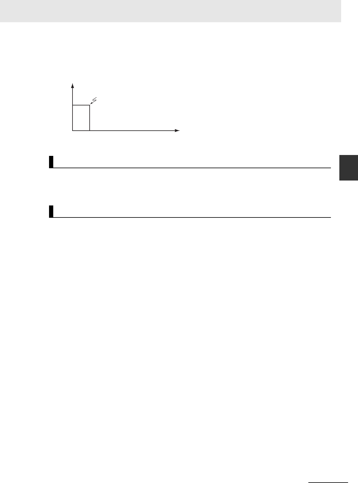
3 Axis Command Instructions
3-267
NJ/NX-series Motion Control Instructions Reference Manual (W508)
MC_GearOut
3
Function
When The Instruction Is Executed with a Deceleration Rate of 0
If deceleration rate is set to 0 and the instruction is executed, the axis will stop without decelerating.
The following chart shows an operation example of when the deceleration rate is 0.
This instruction cannot be re-executed.
A Motion Control Instruction Re-execution Disabled error (error code: 543B hex) occurs if re-execution
is attempted.
For details on multi-execution of motion control instructions, refer to the NJ/NX-series CPU Unit Motion
Control User’s Manual (Cat. No. W507) or NY-series Industrial Panel PC / Industrial Box PC Motion
Control User’s Manual (Cat. No. W559).
Execution during Execution of Other Instructions
If you execute this instruction while MC_GearIn (Start Gear Operation) or MC_GearInPos (Position-
ing Gear Operation) instruction is in execution, CommandAborted for MC_GearIn or MC_GearInPos
will change to TRUE and Busy (Executing) of this instruction will change to TRUE. If you execute this
instruction while instructions other than MC_GearIn or MC_GearInPos are in execution, this instruc-
tion will result in an error.
Execution of Other Instructions during Instruction Execution
To use multi-execution of motion instruction for this instruction, specify the slave axis.
If you execute another instruction during execution of this instruction, you can specify either aborting
or buffering.
Re-execution of Motion Control Instructions
Multi-execution of Motion Control Instructions
Time
MC_GearOut executed.
Velocity

3 Axis Command Instructions
3-268
NJ/NX-series Motion Control Instructions Reference Manual (W508)
If an error occurs during instruction execution, Error will change to TRUE. You can find out the cause of
the error by referring to the value output by ErrorID (Error Code).
Timing Chart When Error Occurs
Error Codes
Refer to A-1 Error Codes for instruction errors.
Errors
Time
Master axis velocity
Velocity
Error code
Busy
CommandAborted
Error
16#0000
ErrorID
Execute
Done

3 Axis Command Instructions
3-269
NJ/NX-series Motion Control Instructions Reference Manual (W508)
MC_MoveLink
3
Variables
MC_MoveLink
Positioning is performed in sync with the specified master axis.
Instruction Name
FB/
FUN
Graphic expression ST expression
MC_MoveLink Synchro-
nous Posi-
tioning
FB MC_MoveLink_instance (
Master :=parameter,
Slave :=parameter,
TriggerInput :=parameter,
TriggerVariable :=parameter,
Execute :=parameter,
ReferenceType :=parameter,
SlaveDistance :=parameter,
MasterDistance :=parameter,
MasterDistanceInACC :=parameter,
MasterDistanceInDEC :=parameter,
LinkOption :=parameter,
MasterStartDistance :=parameter,
BufferMode :=parameter,
Done =>parameter,
InSync =>parameter,
Busy =>parameter,
Active =>parameter,
CommandAborted =>parameter,
Error =>parameter,
ErrorID =>parameter
);
Variables
Input Variables
Name Meaning Data type Valid range Default Description
Execute Execute BOOL TRUE or FALSE FALSE The instruction is executed
when Execute changes to
TRUE.
Reference
Type
*1
Position
Type Selec-
tion
_eMC_
REFERENCE
_TYPE
0: _mcCommand
1: _mcFeedback
2: _mcLatestCommand
0
*2
Specify the position type.
0: Command position
(value calculated in the
previous task period
*3
)
1: Actual position (value
obtained in the same
task period
*3
)
2: Command position
(value calculated in the
same task period
*3
)
SlaveDistance Slave Axis
Travel Dis-
tance
LREAL Negative number, positive
number, or 0
0 Specify the travel distance
of the slave axis. The unit is
command units.
*4
MasterDistanceInACC
MasterDistanceInDEC
LinkOption
MasterStartDistance
BufferMode
MC_MoveLink_instance
ReferenceType
TriggerVariable
Master Master
Slave Slave
TriggerInput TriggerInput
Execute
InSync
Error
ErrorID
CommandAborted
SlaveDistance
ActiveMasterDistance
MC_MoveLink
TriggerVariable
Done
Busy

3 Axis Command Instructions
3-270
NJ/NX-series Motion Control Instructions Reference Manual (W508)
*1 To use _mcLatestCommand, the following condition must be met for the master and slave axes.
When you use _mcLatestCommand, the axis number set for the Master (Master Axis) in the system-defined variable for
motion control must be lower than the axis number set for the Slave (Slave Axis) in the system-defined variable for motion
control.
*2 The default value for an enumeration variable is actually not the number, but the enumerator.
*3 The task period is the primary period if the task is the primary periodic task and the task period of the priority-5 periodic
task if the task is the priority-5 periodic task.
*4 Refer to Unit Conversion Settings in the NJ/NX-series CPU Unit Motion Control User's Manual (Cat. No. W507) or NY-
series Industrial Panel PC / Industrial Box PC Motion Control User’s Manual (Cat. No. W559) for information on command
units.
MasterDistance Master Axis
Travel Dis-
tance
LREAL Non-negative number 0 Specify the travel distance
of the master axis as an
unsigned absolute value.
The value is valid for both
positive and negative travel
of the master axis. The unit
is command units.
*4
Master
DistanceInACC
Master Dis-
tance in
Acceleration
LREAL
Non-negative number
0 Specify the travel distance
of the master axis while the
slave axis is accelerating.
Specify the unsigned abso-
lute value. The value is
valid for both positive and
negative travel of the mas-
ter axis. The unit is com-
mand units.
*3
Master
DistanceInDEC
Master Dis-
tance in
Deceleration
LREAL Non-negative number 0 Specify the travel distance
of the master axis while the
slave axis is decelerating.
Specify the unsigned abso-
lute value. The value is
valid for both positive and
negative travel of the mas-
ter axis. The unit is com-
mand units.
*3
LinkOption Synchroni-
zation Start
Condition
_eMC_
LINKOPTION
0: _mcCommandEexecution
1: _mcTriggerDetection
2: _mcMasterReach
0
*2
Specify the condition for the
slave axis to synchronize
with the master axis.
0: When instruction execu-
tion starts
1: When trigger is detected
2: When the master axis
reaches the master fol-
lowing distance.
MasterStart
Distance
Master Fol-
lowing Dis-
tance
LREAL Negative number, positive
number, or 0
0 Specify the absolute posi-
tion of the master axis
when the slave axis starts
following the master axis.
The unit is command
units.
*3
BufferMode Buffer Mode
Selection
_eMC_
BUFFER_ MODE
0: _mcAborting
1: _mcBuffered
0
*2
Specify the behavior when
executing more than one
motion instruction.
0: Aborting
1: Buffered
Name Meaning Data type Valid range Default Description

3 Axis Command Instructions
3-271
NJ/NX-series Motion Control Instructions Reference Manual (W508)
MC_MoveLink
3
Variables
*Refer to A-1 Error Codes.
Output Variable Update Timing
Output Variables
Name Meaning Data type Valid range Description
Done Done BOOL TRUE or FALSE TRUE when the instruction is completed.
InSync In Sync BOOL TRUE or FALSE TRUE when synchronization is started.
Busy Executing BOOL TRUE or FALSE TRUE when the instruction is acknowledged.
Active Controlling BOOL TRUE or FALSE TRUE when the axis is being controlled.
CommandAborted Command
Aborted
BOOL TRUE or FALSE TRUE when the instruction is aborted.
Error Error BOOL TRUE or FALSE TRUE while there is an error.
ErrorID Error Code WORD
*
Contains the error code when an error occurs.
A value of 16#0000 indicates normal execution.
Name Timing for changing to TRUE Timing for changing to FALSE
Done When the instruction is completed. • When Execute is TRUE and changes to
FALSE.
• After one period when Execute is
FALSE.
InSync When synchronization conditions are met. • When Done changes to TRUE.
• When Error changes to TRUE.
• When CommandAborted changes to
TRUE.
Busy When Execute changes to TRUE. • When Done changes to TRUE.
• When Error changes to TRUE.
• When CommandAborted changes to
TRUE.
Active When an instruction is received. • When Done changes to TRUE.
• When Error changes to TRUE.
• When CommandAborted changes to
TRUE.
CommandAborted • When this instruction is aborted because another
motion control instruction was executed with the Buf-
fer Mode set to Aborting.
• When this instruction is canceled due to an error.
• When this instruction is executed while there is an
error.
• When you start this instruction during MC_Stop
instruction execution.
• When Execute is TRUE and changes to
FALSE.
• After one period when Execute is
FALSE.
Error When there is an error in the execution conditions or
input parameters for the instruction.
When the error is cleared.

3 Axis Command Instructions
3-272
NJ/NX-series Motion Control Instructions Reference Manual (W508)
*1 Specify a user-defined Axis Variable that was created in the Axis Basic Settings of the Sysmac Studio (default:
MC_Axis***) or a system-defined axis variable name (_MC_AX[*], _MC1_AX[*], or _MC2_AX[*]).
*2 Define a user-defined variable with a data type of _sTRIGGER_REF..
_sTRIGGER_REF
• The MC_MoveLink instruction moves a slave axis in synchronization with a specified master axis.
• A type of electronic cam operation is performed, but synchronous positioning is performed between
the slave axis and the master axis.
• Use MC_Stop to stop the axis during motion for this instruction.
Precautions for Correct UsePrecautions for Correct Use
Do not execute the MC_SetPosition instruction for the Master (Master Axis) if you use this
instruction on a CPU Unit with unit version 1.09 or earlier. If the MC_SetPosition instruction is
executed for the Master (Master Axis), the Slave (Slave Axis) may follow the Master (Master
Axis) quickly.
If you want to use the MC_SetPosition instruction for the Master (Master Axis), disable the rela-
tionship between the Master (Master Axis) and Slave (Slave Axis) executing the instruction.
Refer to Precautions for Master and Auxiliary Axes in Synchronized Control on page 1-6 for pre-
cautions on the master axis.
Mapping Data Objects
You must map the following object data when LinkOption (Synchronization Start Condition) is set to
_mcTriggerDetection and the MC_MoveLink (Synchronous Positioning) instruction executed with
Mode set to Drive Mode. Mapping is performed in the Detailed Setting Area of the Axis Basic Set-
tings Display of the Sysmac Studio.
In-Out Variables
Name Meaning Data type Valid range Description
Master Master Axis _sAXIS_REF ---
Specify the master axis.
*1
Slave Slave Axis _sAXIS_REF ---
Specify the slave axis.
*1
TriggerInput Trigger Input
Condition
_sTRIGGER_REF ---
Set the trigger condition.
*2
TriggerVariable Trigger Vari-
able
BOOL TRUE or
FALSE
Specify the input variable to function as the trigger
to specify the controller mode with a trigger condi-
tion.
Name Meaning Data type Valid range Function
Mode Mode _eMC_Trigger_
Mode
0: _mcDrive
1: _mcController
Specify the trigger mode.
0: Drive Mode
1: Controller Mode
LatchID Latch ID
Selection
_eMC_Trigger_
Latch_ID
0: _mcLatch1
1: _mcLatch2
Specify which of the two latch functions to use
in Drive Mode.
0: Latch 1
1: Latch 2
InputDrive Trigger
Input Sig-
nal
_eMC_Trigger_
Input _Drive
0: _mcEncoderMark
1: _mcEXT
Specify the Servo Drive trigger signal to use in
Drive Mode.
0: Z-phase signal
1: External input
Function

3 Axis Command Instructions
3-273
NJ/NX-series Motion Control Instructions Reference Manual (W508)
MC_MoveLink
3
Function
• Touch probe function (60B8 hex)
• Touch probe status (60B9 hex)
• Touch probe pos1 pos value (60BA hex)
• Touch probe pos2 pos value (60BC hex)
If even one of the required objects is not set, a Process Data Object Setting Missing error (error
code 3461 hex) occurs.
For details on mapping data objects, refer to 2-3 PDO Mapping and to the NJ/NX-series CPU Unit
Motion Control User’s Manual (Cat. No. W507) or NY-series Industrial Panel PC / Industrial Box PC
Motion Control User’s Manual (Cat. No. W559).
Refer to I/O Entry Mappings in the NX-series Position Interface Units User’s Manual (Cat. No. W524)
for information on using the NX-series Position Interface Units.
This section describes the instruction in detail.
Master (Master Axis)
Specify the master axis with Master.
Slave (Slave Axis)
Specify the slave axis with Slave.
TriggerInput (Trigger Input Condition) and TriggerVariable
These variables specify the input signal on which to start synchronization when the sync start condi-
tion is set to _mcTriggerDectection. For the input signal selection and information on the timing
when a trigger is generated, refer to MC_TouchProbe on page 3-336. If the Drive Mode is specified
for Mode in TriggerInput (Trigger Input Condition), a drive input from the slave axis is used. If the
Controller Mode is specified, TriggerVariable is used as the trigger signal.
ReferenceType (Position Type Selection)
You can select one of the following position types.
• _mcCommand: Command position (value calculated in the previous task period)
The master axis command position that was calculated in the previous task period is used for the
current period.
The command value that was calculated for the master axis in the last periodic task is used to cal-
culate the command position of the slave axis in the current period.
• _mcFeedback: Value obtained in the same task period
The actual position of the master axis that was obtained in the same task period is used.
• _mcLatestCommand: Command position (value calculated in the same task period)
The command position of the master axis that was calculated in the same task period is used.
This enables the use of information that is more recent than for _mcCommand. However, the axis
number of the master axis must be set lower than the axis number of the slave axis.
If the axis number of the slave axis is lower than the axis number of the master axis, Error will
change to TRUE. A Master/Slave Axis Numbers Not in Ascending Order error (error code: 5438
hex) will be output to ErrorID.
Precautions for Correct UsePrecautions for Correct Use
Here, the task period is the primary period if the task is the primary periodic task and the task
period of the priority-5 periodic task if the task is the priority-5 periodic task. In the same way, the
periodic task is the primary periodic task or the priority-5 periodic task.
Instruction Details

3 Axis Command Instructions
3-274
NJ/NX-series Motion Control Instructions Reference Manual (W508)
Additional Information
The command position that is calculated in the same task period enables greater precision in
synchronization than the command position that was calculated in the previous task period.
However, the axis number set for the Master (Master Axis) in the system-defined variable for
motion control must be lower than the axis number set for the Slave (Slave Axis) in the system-
defined variable for motion control.
Relationship between Axis Types and Position Types
The relationship between the axis types that you can monitor and position types that is monitored is
shown below.
* A Position Type Selection Out of Range error (error code: 5430 hex) occurs when the instruction is executed.
SlaveDistance (Slave Axis Travel Distance), MasterDistance (Master Axis
Travel Distance), MasterDistanceInACC (Master Distance in Acceleration),
and MasterDistanceInDEC (Master Distance in Deceleration)
The velocity and position of the slave axis are determined by the ratio of the travel distances of the
master axis and the slave axis as shown in the following figure. The master following distance shown
in the following figure represents the position where the sync start condition was met.
Master Axis Travel in Positive Direction
Axis Type
ReferenceType
_mcCommand or _mcLatestCommand _mcFeedback
Servo axis OK OK
Encoder axis
No
*
OK
Virtual servo axis OK OK
Virtual encoder axis
No
*
OK
MasterDistanceInDEC
MasterDistanceInACC
MasterDistance
SlaveDistance
Time
Time
Slave axis velocity
Time
Slave axis position
Master
following
distance
Master axis position

3 Axis Command Instructions
3-275
NJ/NX-series Motion Control Instructions Reference Manual (W508)
MC_MoveLink
3
Function
Master Axis Travel in Negative Direction
The relationship between the travel distance of the master axis and the travel distance of the slave
axis is shown in the following table.
When the constant velocity section of the master axis is negative, a constant velocity travel distance
error occurs and the axis stops. If you want to feed the slave axis at the same velocity as the master
axis, set the following value as the travel distance of the slave axis.
Precautions for Correct UsePrecautions for Correct Use
If the counter mode for the master axis is Rotary Mode, specify a value that is within one ring
counter cycle for MasterDistance (Master Axis Travel Distance).
Section Relationship between the master axis and slave axis travel distances
Accelera-
tion
Master axis Master Distance in Acceleration
Slave axis
Constant
velocity
Master axis Master axis travel distance − Master distance in acceleration − Master distance in
deceleration
Slave axis Slave axis travel distance − Slave axis travel distance at the acceleration rate above
− Slave axis travel distance at the deceleration rate below
Decelera-
tion
Master axis Master Distance in Deceleration
Slave axis
MasterDistanceInDEC
MasterDistanceInACC
MasterDistance
SlaveDistance
Master axis position
Slave axis position
Slave axis velocity
Time
Time
Time
Master
following
distance
×
2
+
2
2
+
Master distance
in deceleration
Master axis travel distance − Master distance in
acceleration − Master distance in deceleration
Master distance
in acceleration
Slave axis
travel
distance
Master distance in acceleration
×
2
+
+
2
2
Master distance in deceleration
Master distance
in acceleration
Master axis travel distance − Master distance in
acceleration − Master distance in deceleration
Master distance
in deceleration
Slave axis
travel
distance
=
2
+
+
2
Slave axis
travel distance
Master distance
in acceleration
Master distance
in deceleration
Master axis travel distance − Master distance in
acceleration − Master distance in deceleration

3 Axis Command Instructions
3-276
NJ/NX-series Motion Control Instructions Reference Manual (W508)
LinkOption (Synchronization Start Condition)
Specify the condition for the slave axis to synchronize with the master axis.
• Start of Instruction
When this instruction is executed, the slave axis performs positioning in synchronization with the
master axis from the next period.
• When Trigger Is Detected
When the input signal specified as the input trigger occurs, the slave axis synchronizes with the
master axis and performs positioning from the next period.
• When the Master Axis Reaches the Master Following Distance
When the master axis reaches the master following distance during instruction execution, the
slave axis starts synchronization and performs positioning from the next period.
Even if the instruction is executed while the master axis is stopped at the master following dis-
tance, the slave axis starts synchronization and performs positioning from the next period.
Precautions for Correct UsePrecautions for Correct Use
You must map object data when LinkOption (Synchronization Start Condition) is set to _mcTrigg-
erDetection and Mode is set to Drive Mode. Set the following objects.
• Touch probe function (60B8 hex)
• Touch probe status (60B9 hex)
• Touch probe pos1 pos value (60BA hex)
• Touch probe pos2 pos value (60BC hex)
If even one of the required objects is not set, a Process Data Object Setting Missing error (error
code 3461 hex) occurs. For details on mapping object data, refer to the NJ/NX-series CPU Unit
Motion Control User’s Manual (Cat. No. W507) or NY-series Industrial Panel PC / Industrial Box
PC Motion Control User’s Manual (Cat. No. W559).
MasterStartDistance
MasterStartDistance specifies the absolute position where the slave axis starts synchronization with
the master axis.
CPU Units with Unit Version 1.10 or Later
When the Count Mode of the master axis is Rotary Mode, you can specify a MasterStartDistance
(Master Following Distance) outside the range specified by the modulo maximum position and mod-
ulo minimum position setting values. If you do, the relationship between the master axis current posi-
tion and the master axis following distance will be the same as when no direction is specified for
Direction in the MC_MoveAbsolute (Absolute Positioning) instruction. Refer to MC_MoveAbsolute
on page 3-49 for information on the MC_MoveAbsolute (Absolute Positioning) instruction.
CPU Units with Unit Version 1.09 or Earlier
If the Count Mode for the master axis is Rotary Mode, specify a value that is within the range speci-
fied by the modulo maximum position and modulo minimum position setting values for MasterStart-
Distance (Master Following Distance). If the value is not within the limits, an Cam Master Axis
Following First Position Setting Out of Range error (error code 547B hex) is output when the instruc-
tion is executed.

3 Axis Command Instructions
3-277
NJ/NX-series Motion Control Instructions Reference Manual (W508)
MC_MoveLink
3
Function
BufferMode (Buffer Mode Selection)
BufferMode specifies how to join the axis motions for this instruction and the previous instruction.
There is currently only the following two settings.
For details on BufferMode (Buffer Mode Selection), refer to the NJ/NX-series CPU Unit Motion Con-
trol User's Manual (Cat. No. W507) or NY-series Industrial Panel PC / Industrial Box PC Motion Con-
trol User’s Manual (Cat. No. W559).
In-position Check
An in-position check is performed when the slave axis ends operation.
An in-position check is performed for this instruction according to the settings in In-position Range
and In-position Check Time axis parameters.
Executing MC_MoveLink
LinkOption Set to _mcCommandExecution
Buffer Mode Selection Description
Aborting Aborts the instruction being executed and switches to this instruction.
Buffered Automatically executes the buffered instruction after the current instruction is
completed.
Timing Charts
Busy
InSync
Execute
Done
Active
Master axis
Slave axis
Time
Time
Slave axis
velocity
Master/slave axis position

3 Axis Command Instructions
3-278
NJ/NX-series Motion Control Instructions Reference Manual (W508)
LinkOption Set to _mcTriggerDetection
Slave axis
velocity
Time
Time
Slave axis
Master axis
Master/slave axis position
Busy
InSync
Execute
Done
Active
TriggerInput

3 Axis Command Instructions
3-279
NJ/NX-series Motion Control Instructions Reference Manual (W508)
MC_MoveLink
3
Function
Sync Start Condition Setting = When the Master Axis Reaches the Master
Following Distance
Slave
axis
velocity
Time
Time
Slave axis
Master axis
Master/slave axis position
Busy
InSync
Execute
Done
Active
Master
following
distance

3 Axis Command Instructions
3-280
NJ/NX-series Motion Control Instructions Reference Manual (W508)
When an Instruction Is Executed with BufferMode Set to Aborting during
Previous Operation
This section describes when this instruction is executed with LinkOption set to _mcCommandExecu-
tion when the previous operation, MC_MoveAbsolute (Absolute Positioning), is in execution.
Precautions for Correct UsePrecautions for Correct Use
As shown in the following chart, the velocity of the slave axis becomes discontinuous when this
instruction is started.
When an Instruction Is Executed with BufferMode Set to Buffered during
Previous Operation
This instruction is executed after the previous instruction is finished.
Time
The velocity changes
discontinuously when
MC_MoveLink is started.
Slave axis velocity
Current Instruction
Previous Instruction: MC_MoveAbsolute (Absolute Positioning)
Busy
Done
CommandAborted
Active
Execute
Busy
InSync
CommandAborted
Active
Execute
Done

3 Axis Command Instructions
3-281
NJ/NX-series Motion Control Instructions Reference Manual (W508)
MC_MoveLink
3
Function
This instruction cannot be re-executed.
A Motion Control Instruction Re-execution Disabled error (error code: 543B hex) occurs if re-execution
is attempted, and the axis stops.
For details on multi-execution of instructions, refer to the NJ/NX-series CPU Unit Motion Control User’s
Manual (Cat. No. W507) or NY-series Industrial Panel PC / Industrial Box PC Motion Control User’s
Manual (Cat. No. W559).
Execution of Other Instructions during Instruction Execution
If you execute another instruction during execution of this instruction, you can specify either aborting
or buffering.
You cannot specify blending.
If an error occurs during instruction execution, Error will change to TRUE and the axis will stop. You can
find out the cause of the error by referring to the value output by ErrorID (Error Code). Refer to Re-exe-
cution of Motion Control Instructions on page 3-281 for the timing chart after an error occurs.
Error Codes
Refer to A-1 Error Codes for instruction errors.
Re-execution of Motion Control Instructions
Multi-execution of Motion Control Instructions
Errors
Time
Error code
Slave axis velocity
Active
Busy
CommandAborted
InSync
Error
16#0000
ErrorID
Execute
Done

3 Axis Command Instructions
3-282
NJ/NX-series Motion Control Instructions Reference Manual (W508)
This sample programming shows the control of a cutter.
The minimum settings required for this sample programming are given below.
Setting Axis Parameters
Axis Types
Count Modes
Ring Counter
Units of Display
Sample Programming
Parameter Settings
Axis Axis Type
Axis 1 Servo axis (master axis)
Axis 2 Servo axis (slave axis)
Axis Count Mode
Axis 1 Rotary Mode
Axis 2 Linear Mode
Axis
Modulo maxi-
mum position
Modulo mini-
mum position
Axis 1 360 0
Axis Unit of Display
Axis 1 degree
Axis 2 mm
Operation Example
Axis 1
Servo axis
Axis 2
Servo axis
Pneumatic actuator

3 Axis Command Instructions
3-283
NJ/NX-series Motion Control Instructions Reference Manual (W508)
MC_MoveLink
3
Sample Programming
Operation Patterns
1
Starting the Master Axis
Axis 1 for the belt conveyer is treated as master axis to feed back the position.
2
Executing the Slave Axis
Axis 2 for the ball screw that moves in the horizontal direction moves in synchronization with
axis 1.
3
Cutting with the Cutter
The pneumatic actuator turns ON when axis 2 is synchronized. The cutter, which is connected
to the pneumatic actuator, descends in a vertical direction and cuts the workpiece.
Main Variables
Ladder Diagram
Name Data type Default Comment
MC_Axis000 _sAXIS_REF --- Axis Variable for the master axis, axis 1.
MC_Axis000.MFaultLvl.Active BOOL FALSE TRUE while there is a minor fault level error for
axis 1.
MC_Axis000.Details.Homed BOOL FALSE TRUE when home is defined for axis 1.
MC_Axis001 _sAXIS_REF --- Axis Variable for the slave axis, axis 2.
MC_Axis001.MFaultLvl.Active BOOL FALSE TRUE while there is a minor fault level error for
axis 2.
MC_Axis001.Details.Homed BOOL FALSE TRUE when home is defined for axis 2.
Pwr1_Status BOOL FALSE This variable is assigned to the Status output
variable from the PWR1 instance of the
MC_Power instruction. This variable changes to
TRUE when the Servo is turned ON.
M_DEC
M_ACC
M_StartPos
S_Dist
M_Dist
Axis 1 position
Axis 2 position
Synchronization
started.
Time
Time

3 Axis Command Instructions
3-284
NJ/NX-series Motion Control Instructions Reference Manual (W508)
Timing Chart
Pwr2_Status BOOL FALSE This variable is assigned to the Status output
variable from the PWR2 instance of the
MC_Power instruction. This variable changes to
TRUE when the Servo is turned ON.
StartPg BOOL FALSE The Servo is turned ON if this variable is TRUE
and EtherCAT process data communications are
established.
Actuator BOOL FALSE TRUE when axis 1 and axis 2 are synchronized.
While Actuator is TRUE, the cutter moves down
vertically.
InitFlag BOOL FALSE This variable indicates if it is necessary to set the
input parameters. Input parameters are set when
this variable is FALSE. When setting the input
parameters is completed, this variable changes to
TRUE.
Name Data type Default Comment
Mv_Link_Bsy
Mv_Link_InSync
MC_Axis001.DrvStatus.Latch1
Mv_Link_D
MC_Axis000.Cmd.Vel
MC_Axis001.Cmd.Vel
Master axis
Slave axis
Velocity
Time
Velocity
Time

3 Axis Command Instructions
3-285
NJ/NX-series Motion Control Instructions Reference Manual (W508)
MC_MoveLink
3
Sample Programming
Sample Programming
StartPg
Lock1
MC_Axis000.DrvStatus.Ready
PWR1
Error
Axis Axis
Enable Status
Busy
MC_Power
ErrorID
Lock1
MC_Axis000
Pwr1_Status
Pwr1_Bsy
Pwr1_Err
Pwr1_ErrID
FaultHandlerMC_Axis000.MFaultLvl.Active
FaultHandlerEN
MC_Axis001.MFaultLvl.Active
HM1
Axis Axis
Execute
Error
ErrorID
CommandAborted
MC_Home
Done
Busy
MC_Axis000
Pwr1_Status
Hm1_D
Hm1_Bsy
Hm1_Ca
Hm1_Err
Hm1_ErrID
MC_Axis000.Details.Homed
HM2
Axis Axis
Execute
Error
ErrorID
CommandAborted
MC_Home
Done
Busy
MC_Axis001
Pwr2_Status
Hm2_D
Hm2_Bsy
Hm2_Ca
Hm2_Err
Hm2_ErrID
MC_Axis001.Details.Homed
Lock2
MC_Axis001.DrvStatus.Ready
PWR2
Error
Axis Axis
Enable Status
Busy
MC_Power
ErrorID
Lock2
MC_Axis001
Pwr2_Status
Pwr2_Bsy
Pwr2_Err
Pwr2_ErrID
If StartPg is TRUE, check that the Servo Drives for each axis are ready.
If the Servo Drives are ready, the Servos are turned ON for each axis.
If a minor fault level error occurs for the axis composition, the error handler for the device (FaultHandler) is executed.
Program the FaultHandler according to the device.
If the Servo is ON for axis 1 and home is not defined, the Home instruction is executed to define home.
If the Servo is ON for axis 2 and home is not defined, the Home instruction is executed to define home.

3 Axis Command Instructions
3-286
NJ/NX-series Motion Control Instructions Reference Manual (W508)
Contents of Inline ST
// MC_MoveVelocity parameters
Vel_Vel := LREAL#1000.0;
Vel_Acc := LREAL#0.0;
Vel_Dec := LREAL#0.0;
// MC_MoveLink parameters
Mv_Link_TrigRef.Mode := _eMC_TRIGGER_MODE#_mcDrive;
Mv_Link_TrigRef.LatchID := _eMC_TRIGGER_LATCH_ID#_mcLatch1;
Mv_Link_TrigRef.InputDrive := _eMC_TRIGGER_INPUT_DRIVE#_mcEXT;
Mv_Link_TrigVar := FALSE;
Mv_Link_SlvDis := LREAL#1000.0;
Mv_Link_MasDis := LREAL#1000.0;
Mv_Link_MasDisInAcc := LREAL#100.0;
Mv_Link_MasDisInDec := LREAL#100.0;
MC_Axis000
MC_Axis000.Details.Homed
Vel_InVel
BufferMode
VEL
Jerk
Active
Axis Axis
Execute InVelocity
Velocity Busy
Deceleration
Error
Direction
Continuous
MC_MoveVelocity
Acceleration
CommandAborted
ErrorID
Vel_Vel
Vel_Acc
Vel_Bsy
Vel_Act
Vel_Ca
Vel_Err
Vel_EIrrD
Vel_Dec
InitFlag
MasterDistanceInACC
MasterDistanceInDEC
LinkOption
MasterStartDistance
BufferMode
MV_LINK
ReferenceType
TriggerVariable
Master
Master
Slave
Slave
TriggerInput TriggerInput
Execute
InSync
Error
ErrorID
CommandAborted
SlaveDistance
ActiveMasterDistance
MC_MoveLink
TriggerVariable
Done
Busy
MC_Axis000
MC_Axis001
Mv_Link_TrigRef
Mv_Link_TrigVar
MC_Axis001.Details.Homed
Mv_Link_SlvDis
Mv_Link_MasDis
Mv_Link_MasDisInAcc
Mv_Link_MasDisInDec
Mv_Link_LnkOpt
Mv_Link_Bsy
Mv_Link_Act
Mv_Link_Ca
Mv_Link_Err
Mv_Link_ErrID
Mv_Link_InSync
Mv_Link_D
Vel_InVel
Actuator
Mv_Link_InSync
The MC_MoveVelocity (Velocity Control) instruction is executed if home is defined for axis 1.
The parameters are set for the MC_MoveVelocity (Velocity Control) and MC_MoveLink (Synchronous Positioning) instructions.
Actuator is TRUE while the axes are synchronized.
The MC_MoveLink (Synchronous Positioning) instruction is executed if home is defined for axis 2 (slave axis).
Note: The contents of the inline ST are
given below.

3 Axis Command Instructions
3-287
NJ/NX-series Motion Control Instructions Reference Manual (W508)
MC_MoveLink
3
Sample Programming
Mv_Link_LnkOpt := _eMC_LINKOPTION#_mcTriggerDetection;
// Change InitFlag to TRUE after setting the input parameters.
InitFlag := TRUE;
Main Variables
Structured Text (ST)
Name Data type Default Comment
MC_Axis000 _sAXIS_REF --- Axis Variable for the master axis, axis 1.
MC_Axis000.MFaultLvl.Active BOOL FALSE TRUE while there is a minor fault level error for
axis 1.
MC_Axis000.Details.Homed BOOL FALSE TRUE when home is defined for axis 1.
MC_Axis001 _sAXIS_REF --- Axis Variable for the slave axis, axis 2.
MC_Axis001.MFaultLvl.Active BOOL FALSE TRUE while there is a minor fault level error for
axis 2.
MC_Axis001.Details.Homed BOOL FALSE TRUE when home is defined for axis 2.
Pwr1_Status BOOL FALSE This variable is assigned to the Status output
variable from the PWR1 instance of the
MC_Power instruction. This variable changes to
TRUE when the Servo is turned ON.
Pwr2_Status BOOL FALSE This variable is assigned to the Status output
variable from the PWR2 instance of the
MC_Power instruction. This variable changes to
TRUE when the Servo is turned ON.
StartPg BOOL FALSE The Servo is turned ON if this variable is TRUE
and EtherCAT process data communications are
established.
Actuator BOOL FALSE TRUE when axis 1 and axis 2 are synchronized.
While Actuator is TRUE, the cutter moves down
vertically.
InitFlag BOOL FALSE This variable indicates if it is necessary to set the
input parameters. Input parameters are set when
this variable is FALSE. When setting the input
parameters is completed, this variable changes to
TRUE.

3 Axis Command Instructions
3-288
NJ/NX-series Motion Control Instructions Reference Manual (W508)
Timing Chart
Mv_Link_Bsy
Mv_Link_InSync
MC_Axis001.DrvStatus.Latch1
Mv_Link_D
Mv_Link_Ex
MC_Axis000.Cmd.Vel
MC_Axis001.Cmd.Vel
Master axis
Slave axis
Velocity
Time
Velocity
Time

3 Axis Command Instructions
3-289
NJ/NX-series Motion Control Instructions Reference Manual (W508)
MC_MoveLink
3
Sample Programming
Sample Programming
// Processing when input parameters are not set
IF InitFlag=FALSE THEN
// MC_MoveVelocity parameters
Vel_Vel := LREAL#1000.0;
Vel_Acc := LREAL#0.0;
Vel_Dec := LREAL#0.0;
// MC_MoveLink parameters
Mv_Link_TrigRef.Mode := _eMC_TRIGGER_MODE#_mcDrive;
Mv_Link_TrigRef.LatchID := _eMC_TRIGGER_LATCH_ID#_mcLatch1;
Mv_Link_TrigRef.InputDrive := _eMC_TRIGGER_INPUT_DRIVE#_mcEXT;
Mv_Link_TrigVar := FALSE;
Mv_Link_SlvDis := LREAL#1000.0;
Mv_Link_MasDis := LREAL#1000.0;
Mv_Link_MasDisInAcc := LREAL#100.0;
Mv_Link_MasDisInDec := LREAL#100.0;
Mv_Link_LnkOpt := _eMC_LINKOPTION#_mcTriggerDetection;
// Change InitFlag to TRUE after setting the input parameters.
InitFlag := TRUE;
END_IF;
// If StartPg is TRUE and the Servo Drive is ready, the Servo for axis 1 is turned ON.
// If the Servo Drive is not ready, the Servo is turned OFF.
IF (StartPg=TRUE)
AND (MC_Axis000.DrvStatus.Ready=TRUE) THEN
Pwr1_En:=TRUE; // Turn ON the Servo for axis 1.
ELSE
Pwr1_En:=FALSE; // Turn OFF the Servo for axis 1.
END_IF;
// If StartPg is TRUE and the Servo Drive is ready, the Servo for axis 2 is turned ON.
// If the Servo Drive is not ready, the Servo is turned OFF.
IF (StartPg=TRUE)
AND (MC_Axis001.DrvStatus.Ready=TRUE) THEN
Pwr2_En:=TRUE; // Turn ON the Servo for axis 2.
ELSE
Pwr2_En:=FALSE; // Turn OFF the Servo for axis 2.
END_IF;
// Processing for a minor fault level error
// Program the FaultHandler according to the device.
IF (MC_Axis000.MFaultLvl.Active=TRUE) OR (MC_Axis001.MFaultLvl.Active=TRUE) THEN
FaultHandler();
END_IF;
// If the Servo is ON for axis 1 and home is not defined, the Home instruction is executed.
IF (Pwr1_Status=TRUE) AND (MC_Axis000.Details.Homed=FALSE) THEN
Hm1_Ex:=TRUE;
END_IF;
// If the Servo is ON for axis 2 and home is not defined, the Home instruction is executed.
IF (Pwr2_Status=TRUE) AND (MC_Axis001.Details.Homed=FALSE) THEN
Hm2_Ex:=TRUE;
END_IF;
// After home is defined for axis 1, MC_MoveVelocity is executed for axis 1.
IF MC_Axis000.Details.Homed=TRUE THEN
Vel_Ex:=TRUE;
END_IF;

3 Axis Command Instructions
3-290
NJ/NX-series Motion Control Instructions Reference Manual (W508)
// MC_MoveLink is executed for axis 2 if home is defined for axis 2 and the target velocity was reached for axis
1.
IF (MC_Axis001.Details.Homed=TRUE) AND (Vel_InVel=TRUE) THEN
Mv_Link_Ex:=TRUE;
END_IF;
// The actuator is turned ON if axis 1 and axis 2 are synchronized.
IF Mv_Link_InSync=TRUE THEN
Actuator:=TRUE;
ELSE
Actuator:=FALSE;
END_IF;
// MC_Power1
PWR1(
Axis := MC_Axis000,
Enable := Pwr1_En,
Status => Pwr1_Status,
Busy => Pwr1_Bsy,
Error => Pwr1_Err,
ErrorID => Pwr1_ErrID
);
// MC_Power2
PWR2(
Axis := MC_Axis001,
Enable := Pwr2_En,
Status => Pwr2_Status,
Busy => Pwr2_Bsy,
Error => Pwr2_Err,
ErrorID => Pwr2_ErrID
);
// MC_Home1
HM1(
Axis := MC_Axis000,
Execute := Hm1_Ex,
Done => Hm1_D,
Busy => Hm1_Bsy,
CommandAborted => Hm1_Ca,
Error => Hm1_Err,
ErrorID => Hm1_ErrID
);
// MC_Home2
HM2(
Axis := MC_Axis001,
Execute := Hm2_Ex,
Done => Hm2_D,
Busy => Hm2_Bsy,
CommandAborted => Hm2_Ca,
Error => Hm2_Err,
ErrorID => Hm2_ErrID
);
// MC_MoveVelocity
VEL(
Axis := MC_Axis000,
Execute := Vel_Ex,
Velocity := Vel_Vel,
Acceleration := Vel_Acc,
Deceleration := Vel_Dec,
InVelocity => Vel_InVel,
Busy => Vel_Bsy,

3 Axis Command Instructions
3-291
NJ/NX-series Motion Control Instructions Reference Manual (W508)
MC_MoveLink
3
Sample Programming
Active => Vel_Act,
CommandAborted => Vel_Ca,
Error => Vel_Err,
ErrorID => Vel_ErrID
);
// MC_MoveLink
MV_LINK(
Master := MC_Axis000,
Slave := MC_Axis001,
TriggerInput := Mv_Link_TrigRef,
TriggerVariable := Mv_Link_TrigVar,
Execute := Mv_Link_Ex,
SlaveDistance := Mv_Link_SlvDis,
MasterDistance := Mv_Link_MasDis,
MasterDistanceInAcc := Mv_Link_MasDisInAcc,
MasterDistanceInDec := Mv_Link_MasDisInDec,
LinkOption := Mv_Link_LnkOpt,
Done => Mv_Link_D,
InSync => Mv_Link_InSync,
Busy => Mv_Link_Bsy,
Active => Mv_Link_Act,
CommandAborted => Mv_Link_Ca,
Error => Mv_Link_Err,
ErrorID => Mv_Link_ErrID
);

3 Axis Command Instructions
3-292
NJ/NX-series Motion Control Instructions Reference Manual (W508)
MC_CombineAxes
The MC_CombineAxes instruction outputs the sum or difference of the command positions of two axes
as the command position.
Instruction Name
FB/
FUN
Graphic expression ST expression
MC_CombineAxes Combine
Axes
FB MC_CombineAxes_instance (
Master :=parameter,
Auxiliary :=parameter,
Slave :=parameter,
Execute :=parameter,
CombineMode :=parameter,
RatioNumeratorMaster
:=parameter,
RatioDenominatorMaster
:=parameter,
RatioNumeratorAuxiliary
:=parameter,
RatioDenominatorAuxiliary
:=parameter,
ReferenceTypeMaster :=parameter,
ReferenceTypeAuxiliary
:=parameter,
BufferMode :=parameter,
InCombination =>parameter,
Busy =>parameter,
Active =>parameter,
CommandAborted =>parameter,
Error =>parameter,
ErrorID =>parameter
);
Variables
Input Variables
Name Meaning Data type Valid range Default Description
Execute Execute BOOL TRUE or FALSE FALSE The instruction is executed
when Execute changes to
TRUE.
CombineMode Combine
Mode
_eMC
_COMBINE_
MODE
0: _mcAddAxes
1: _mcSubAxes
0
*1
Specify the combining method.
0: Addition
1: Subtraction
Ratio
Numerator
Master
(Reserved)
Master Axis
Gear Ratio
Numerator
DINT
*2
Positive or negative num-
ber
*2
10000 Reserved
Ratio
Denominator
Master
(Reserved)
Master Axis
Gear Ratio
Denominator
UDINT
*3
Positive number 10000 Reserved
RatioDenominatorAuxiliary
ReferenceTypeMaster
ReferenceTypeAuxiliary
BufferMode
MC_CombineAxes_instance
RatioNumeratorMaster
InCombination
Master Master
Auxiliary Auxiliary
Slave Slave
CombineMode
Error
ErrorID
CommandAbortedRatioDenominatorMaster
Active
RatioNumeratorAuxiliary
MC_CombineAxes
Execute
Busy

3-293
3 Axis Command Instructions
NJ/NX-series Motion Control Instructions Reference Manual (W508)
MC_CombineAxes
3
Variables
*1 The default value for an enumeration variable is actually not the number, but the enumerator.
*2 A CPU Unit with unit version 1.02 or later and Sysmac Studio version 1.03 or higher are required to use this variable. For
any previous version combinations, the data type is UINT and the valid range is positive numbers.
*3 A CPU Unit with unit version 1.02 or later and Sysmac Studio version 1.03 or higher are required to use this variable. For
any previous version combinations, the data type is UINT.
*4 The task period is the primary period if the task is the primary periodic task and the task period of the priority-5 periodic
task if the task is the priority-5 periodic task.
*Refer to A-1 Error Codes.
Ratio
Numerator
Auxiliary
(Reserved)
Auxiliary Axis
Gear Ratio
Numerator
DINT
*2
Positive or negative num-
ber
*2
10000 Reserved
Ratio
Denominator
Auxiliary
(Reserved)
Auxiliary Axis
Gear Ratio
Denominator
UDINT
*3
Positive number 10000 Reserved
Reference
TypeMaster
Master Axis
Position Type
Selection
_eMC_
REFERENCE_
TYPE
1: _mcFeedback
2: _mcLatestCommand
2
*1
Specify the position type of the
master axis.
1: Actual position (value
obtained in the same task
period
*4
)
2: Command position (value
calculated in the same task
period
*4
)
Reference
TypeAuxiliary
Auxiliary Axis
Position Type
Selection
_eMC_
REFERENCE_
TYPE
1: _mcFeedback
2: _mcLatestCommand
2
*1
Specify the position type of the
auxiliary axis.
1: Actual position (value
obtained in the same task
period
*4
)
2: Command position (value
calculated in the same task
period
*4
)
BufferMode Buffer Mode
Selection
_eMC
_BUFFER_
MODE
0: _mcAborting
0
*1
Specify the behavior when exe-
cuting more than one motion
instruction.
0: Aborting
Output Variables
Name Meaning Data type Valid range Description
InCombination Axes
Combined
BOOL TRUE or
FALSE
TRUE when axes are combined.
Busy Executing BOOL TRUE or
FALSE
TRUE when the instruction is acknowledged.
Active Controlling BOOL TRUE or
FALSE
TRUE when the axis is being controlled.
CommandAborted Command
Aborted
BOOL TRUE or
FALSE
TRUE when the instruction is aborted.
Error Error BOOL TRUE or
FALSE
TRUE while there is an error.
ErrorID Error Code WORD
*
Contains the error code when an error occurs.
A value of 16#0000 indicates normal execution.
Name Meaning Data type Valid range Default Description

3 Axis Command Instructions
3-294
NJ/NX-series Motion Control Instructions Reference Manual (W508)
Output Variable Update Timing
* Specify a user-defined Axis Variable that was created in the Axis Basic Settings of the Sysmac Studio (default: MC_Axis***)
or a system-defined axis variable name (_MC_AX[*], _MC1_AX[*], or _MC2_AX[*]).
Precautions for Correct UsePrecautions for Correct Use
One of the following minor faults will occur if the different axes are not used for the master, slave,
and auxiliary axes.
• Master and Slave Defined as Same Axis (error code 5436 hex)
• Master and Auxiliary Defined as Same Axis (error code 5437 hex)
• Auxiliary and Slave Defined as Same Axis (error code 548E hex)
Name Timing for changing to TRUE Timing for changing to FALSE
InCombination When combining axes is started. • When Error changes to TRUE.
• When CommandAborted changes to
TRUE.
Busy When Execute changes to TRUE. • When Error changes to TRUE.
• When CommandAborted changes to
TRUE.
Active When the instruction is started. • When Error changes to TRUE.
• When CommandAborted changes to
TRUE.
CommandAborted • When this instruction is aborted because another
motion control instruction was executed with the
Buffer Mode set to Aborting.
• When this instruction is canceled due to an error.
• When this instruction is executed while there is an
error.
• When you start this instruction during MC_Stop
instruction execution.
• When Execute is TRUE and changes to
FALSE.
• After one period when Execute is FALSE.
Error When there is an error in the execution conditions or
input parameters for the instruction.
When the error is cleared.
In-Out Variables
Name Meaning Data type Valid range Description
Master Master Axis _sAXIS_REF ---
Specify the master axis.
*
Auxiliary Auxiliary Axis _sAXIS_REF ---
Specify the auxiliary axis.
*
Slave Slave Axis _sAXIS_REF ---
Specify the slave axis.
*
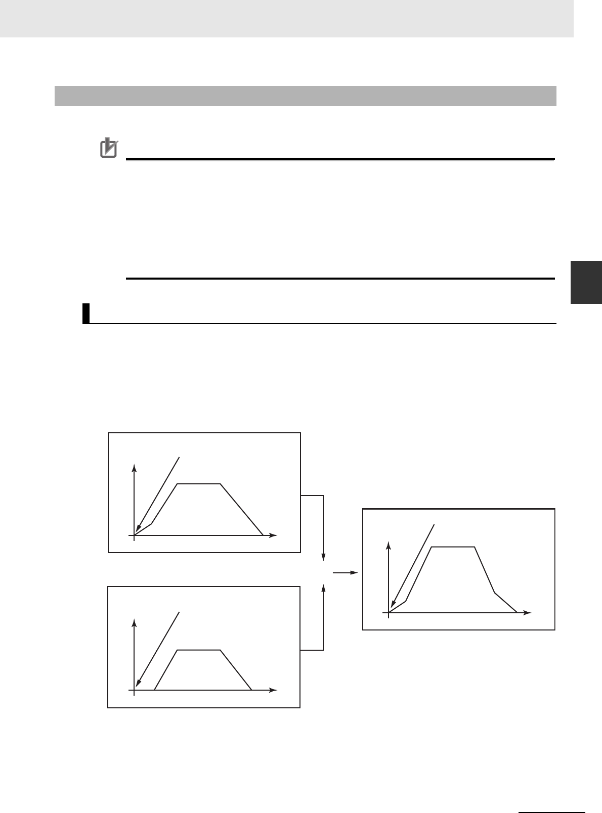
3-295
3 Axis Command Instructions
NJ/NX-series Motion Control Instructions Reference Manual (W508)
MC_CombineAxes
3
Function
• The MC_CombineAxes instruction starts combining axes when Execute changes to TRUE.
Precautions for Correct UsePrecautions for Correct Use
Do not execute the MC_SetPosition instruction for the Master (Master Axis) if you use this
instruction on a CPU Unit with unit version 1.09 or earlier. If the MC_SetPosition instruction is
executed for the Master (Master Axis), the Slave (Slave Axis) may follow the Master (Master
Axis) quickly.
If you want to use the MC_SetPosition instruction for the Master (Master Axis), disable the rela-
tionship between the Master (Master Axis) and Slave (Slave Axis) executing the instruction.
Refer to Precautions for Master and Auxiliary Axes in Synchronized Control on page 1-6 for pre-
cautions on the master axis. This precaution also applies to Auxiliary (Auxiliary Axis) in the same
way as for Master (Master Axis).
From the starting point, the relative value of the Auxiliary (Auxiliary Axis) position is added to or sub-
tracted from the relative value of the Master (Master Axis) position and is output as a relative value for
the Slave (Slave Axis) command position.
CombineMode Set to _mcAddAxes
Slave (Slave Axis) position = Master (Master Axis) position (relative position) + Auxiliary (Auxiliary
Axis) position (relative position)
Function
Instruction Details
+
Time
Position: 600
Time
Position: 500
Position: 0
Execute of
MC_CombineAxes
changes to TRUE
Slave
Position: 200
Time
Position: 200
Position: 100
Execute of
MC_CombineAxes changes
to TRUE
Auxiliary
Execute of
MC_CombineAxes
changes to TRUE
Master
Velocity
Velocity
Velocity

3 Axis Command Instructions
3-296
NJ/NX-series Motion Control Instructions Reference Manual (W508)
CombineMode Set to _mcSubAxes
Slave (Slave Axis) position = Master (Master Axis) position (relative position) − Auxiliary (Auxiliary
Axis) position (relative position)
• Adding or subtracting the position is performed as numerical operations without considering the
Unit of Display for the axis in the axis parameters.
• Execute the MC_Stop instruction to end this instruction.
Precautions for Correct UsePrecautions for Correct Use
Depending on the values for the Master (Master Axis) and Auxiliary (Auxiliary Axis), the travel
distance, velocity, and acceleration of the Slave (Slave Axis) can change rapidly.
Use this setting with care.
In-position Check
An in-position check is not performed for this instruction.
Override Factors
You cannot perform an MC_SetOverride (Set Override Factors) override for this instruction.
ReferenceType (Position Type Selection)
You can select one of the following position types.
• _mcFeedback: Value obtained in the same task period
The actual position of the master axis that was obtained in the same task period is used.
• _mcLatestCommand: Command position (value calculated in the same task period)
The command position of the master axis that was calculated in the same task period is used.
However, if _mcLatestCommand is selected, the axis numbers of the master axis and auxiliary
axis must be set lower than the axis number of the slave axis. If the axis numbers of the slave axis
or auxiliary axis is lower than the axis number of the master axis, Error will change to TRUE. A
Master/Slave Axis Numbers Not in Ascending Order error (error code: 5438 hex) will be output to
ErrorID. There are no restrictions in the relationship of the axis numbers between the master axis
and the auxiliary axis.
Time
Position: 600
Time
Position: 390
Position: 0
Execute of
MC_CombineAxes
changes to TRUE
Position: 200
Time
Position: 110
Position: 100
Execute of
MC_CombineAxes
changes to TRUE
Execute of
MC_CombineAxes
changes to TRUE
Velocity
Velocity
Velocity
Master
Auxiliary
Slave
-

3-297
3 Axis Command Instructions
NJ/NX-series Motion Control Instructions Reference Manual (W508)
MC_CombineAxes
3
Function
Precautions for Correct UsePrecautions for Correct Use
Here, the task period is the primary period if the task is the primary periodic task and the task
period of the priority-5 periodic task if the task is the priority-5 periodic task. In the same way, the
periodic task is the primary periodic task or the priority-5 periodic task.
Relationship between Axis Types and Position Types
The relationship between the axis types that you can monitor and position types that is monitored is
shown below.
* A Position Type Selection Out of Range error (error code: 5430 hex) occurs when the instruction is executed.
• Busy (Executing) changes to TRUE at the same time as Execute changes to TRUE. Active (Con-
trolling) changes to TRUE in the next period.
• InCombination (Axes Combined) changes to TRUE in the period where the combined output starts.
• If another instruction aborts this instruction, CommandAborted changes to TRUE and Busy (Execut-
ing), Active (Controlling), and InCombination (Axes Combined) change to FALSE.
Axis Type
ReferenceType
_mcFeedback _mcLatestCommand
Servo axis OK OK
Encoder axis OK
No
*
Virtual servo axis OK OK
Virtual encoder axis OK
No
*
Timing Charts

3 Axis Command Instructions
3-298
NJ/NX-series Motion Control Instructions Reference Manual (W508)
CombineMode Set to _mcAddAxes
Time
Time
Time
Slave axis position
Auxiliary axis position
Master axis position
16#0000
Execute
Busy
Active
InCombination
Command Aborted
Error
ErrorID

3-299
3 Axis Command Instructions
NJ/NX-series Motion Control Instructions Reference Manual (W508)
MC_CombineAxes
3
Function
CombineMode Set to _mcSubAxes
Time
Time
Time
Slave axis position
Auxiliary axis position
Master axis position
16#0000
Execute
Busy
Active
InCombination
Command Aborted
Error
ErrorID

3 Axis Command Instructions
3-300
NJ/NX-series Motion Control Instructions Reference Manual (W508)
When the Instruction Is Aborted
This instruction cannot be re-executed.
A Motion Control Instruction Re-execution Disabled error (error code: 543B hex) occurs if re-execution
is attempted.
For details on multi-execution of motion control instructions, refer to the NJ/NX-series CPU Unit Motion
Control User’s Manual (Cat. No. W507) or NY-series Industrial Panel PC / Industrial Box PC Motion
Control User’s Manual (Cat. No. W559).
Execution of Other Instructions during Instruction Execution
To use multi-execution of instructions for this instruction, specify the slave axis.
When performing multi-execution of another instruction while this instruction is in execution, the fol-
lowing limits apply depending on BufferMode (Buffer Mode Selection).
• You can execute another instruction with the Buffer Mode set to Aborting during execution of this
instruction. You cannot specify Buffered or a blending mode.
Re-execution of Motion Control Instructions
Multi-execution of Motion Control Instructions
Time
Time
Time
Multi-execution of
another instruction
Slave axis position
Auxiliary axis position
Master axis position
16#0000
Execute
Busy
Active
InCombination
Command Aborted
Error
ErrorID
Operation for multi-
execution of instructions

3-301
3 Axis Command Instructions
NJ/NX-series Motion Control Instructions Reference Manual (W508)
MC_CombineAxes
3
Function
Timing Chart When Error Occurs
If an error occurs during instruction execution, Error will change to TRUE and the axis will stop. The
axis decelerates to a stop at the maximum deceleration rate that is set in the axis parameters. You
can find out the cause of the error by referring to the value output by ErrorID (Error Code).
Additional Information
• This instruction is not affected by errors in the Master (Master Axis) or the Auxiliary (Auxiliary
Axis).
• After the error is cleared and the Master (Master Axis) or the Auxiliary (Auxiliary Axis) is in
motion, the Slave (Slave Axis) will resume the combined positioning operation. The Master
(Master Axis) or the Auxiliary (Auxiliary Axis) are not affected if an error occurs for the slave
axis during startup or execution of this instruction, but this instruction is aborted.
Errors
Error ID
Time
Time
Time
Slave axis position
Auxiliary axis position
Master axis position
16#0000
Execute
Busy
Active
InCombination
Command Aborted
Error
ErrorID

3 Axis Command Instructions
3-302
NJ/NX-series Motion Control Instructions Reference Manual (W508)
If a minor fault level error occurs during instruction execution, CommandAborted will change to
TRUE and the axis will stop.
The axis decelerates to a stop at the maximum deceleration rate that is set in the axis parameters.
You can find out the cause of the error by referring to the value output to the MFalutLvl.Code Axis
Variable for the Slave (Slave Axis).
Error occurs.
Time
Time
Time
Slave axis position
Auxiliary axis position
Master axis position
Execute
Busy
Active
InCombination
Command Aborted
Error
ErrorID
16#0000

3-303
3 Axis Command Instructions
NJ/NX-series Motion Control Instructions Reference Manual (W508)
MC_CombineAxes
3
Function
If you clear the error for this instruction, the instruction will not start until Execute changes to TRUE
again.
Error Codes
Refer to A-1 Error Codes for instruction errors.
Time
Time
Time
Slave axis position
Auxiliary axis position
Master axis position
Error code
Error reset.
16#0000
Execute
Busy
Active
InCombination
Command Aborted
Error
ErrorID

3 Axis Command Instructions
3-304
NJ/NX-series Motion Control Instructions Reference Manual (W508)
MC_Phasing
The MC_Phasing instruction shifts the phase of the master axis currently in synchronized control.
*1 Refer to Unit Conversion Settings in the NJ/NX-series CPU Unit Motion Control User's Manual (Cat. No. W507) or NY-
series Industrial Panel PC / Industrial Box PC Motion Control User’s Manual (Cat. No. W559) for information on command
units.
Instruction Name FB/FUN Graphic expression ST expression
MC_Phasing Shift Master Axis
Phase
FB MC_Phasing_instance (
Master :=parameter,
Slave :=parameter,
Execute :=parameter,
PhaseShift :=parameter,
Velocity :=parameter,
Acceleration :=parameter,
Deceleration :=parameter,
Jerk :=parameter,
BufferMode :=parameter,
Done =>parameter,
Busy =>parameter,
Active =>parameter,
CommandAborted
=>parameter,
Error =>parameter,
ErrorID =>parameter
);
Variables
Input Variables
Name Meaning Data type Valid range Default Description
Execute Execute BOOL TRUE or FALSE FALSE The instruction is executed when
Execute changes to TRUE.
PhaseShift Phase Shift
Amount
LREAL Negative number, posi-
tive number, or 0
0 Specify the master axis phase
shift amount. The unit is com-
mand units.
*1
Velocity Target
Velocity
LREAL Positive number 0 Specify the target velocity for the
phase shift amount.
*2
Specify the target velocity. The
unit is command units/s.
*1
Acceleration Acceleration
Rate
LREAL Non-negative number 0 Specify the acceleration rate.
The unit is command units/s
2
.
*1
Deceleration Deceleration
Rate
LREAL Non-negative number 0 Specify the deceleration rate.
The unit is command units/s
2
.
*1
Jerk Jerk LREAL Non-negative number 0 Specify the jerk. The unit is com-
mand units/s
3
.
*1
BufferMode Buffer Mode
Selection
_eM-
C_BUFFER_-
MODE
0: _mcAborting
0
*3
Specify the behavior when exe-
cuting more than one motion
instruction.
0: Aborting
BufferMode
MC_Phasing_instance
Acceleration
Master Master
Slave Slave
Execute
Velocity
Error
ErrorID
CommandAborted
Deceleration
Active
Jerk
MC_Phasing
PhaseShift
Done
Busy

3-305
3 Axis Command Instructions
NJ/NX-series Motion Control Instructions Reference Manual (W508)
MC_Phasing
3
Variables
*2 Always set the target velocity. A Target Velocity Setting Out of Range error (error code: 5422 hex) occurs when the
instruction is executed if the target velocity is not set.
*3 The default value for an enumeration variable is actually not the number, but the enumerator.
*Refer to A-1 Error Codes.
Output Variables
Name Meaning Data type Valid range Description
Done Done BOOL TRUE or
FALSE
TRUE when the instruction is completed.
Busy Executing BOOL TRUE or
FALSE
TRUE when the instruction is acknowledged.
Active Controlling BOOL TRUE or
FALSE
TRUE when the axis is being controlled.
CommandAborted Command
Aborted
BOOL TRUE or
FALSE
TRUE when the instruction is aborted.
Error Error BOOL TRUE or
FALSE
TRUE while there is an error.
ErrorID Error Code WORD
*
Contains the error code when an error occurs.
A value of 16#0000 indicates normal execution.

3 Axis Command Instructions
3-306
NJ/NX-series Motion Control Instructions Reference Manual (W508)
Output Variable Update Timing
* Specify a user-defined Axis Variable that was created in the Axis Basic Settings of the Sysmac Studio (default: MC_Axis***)
or a system-defined axis variable name (_MC_AX[*], _MC1_AX[*], or _MC2_AX[*]).
Precautions for Correct UsePrecautions for Correct Use
If you specify the same axis for the master axis and slave axis, a Master and Slave Defined as
Same Axis minor fault (error code 5436 hex) will occur.
• Except during execution of the MC_CombineAxes instruction, if the MC_Phasing instruction is exe-
cuted when single-axis synchronized control is in progress, the phase of the master axis is shifted
according to the settings of the PhaseShift (Phase Shift Amount), Velocity (Target Velocity), Acceler-
ation (Acceleration Rate), and Deceleration (Deceleration Rate).
• The command current position and actual current position of the master axis do not change, and the
relative shift between the command current position and actual current position of the master axis is
taken as the phase of the master axis. The slave axis is synchronized to the shifted master axis
phase.
• Done changes to TRUE when the PhaseShift (Phase Shift Amount) is reached.
Name Timing for changing to TRUE Timing for changing to FALSE
Done When phase shift is completed. • When Execute is TRUE and changes to
FALSE.
• After one period when Execute is FALSE.
Busy When Execute changes to TRUE. • When Done changes to TRUE.
• When Error changes to TRUE.
• When CommandAborted changes to
TRUE.
Active When phase shift is started. • When Done changes to TRUE.
• When Error changes to TRUE.
• When CommandAborted changes to
TRUE.
CommandAborted • When this instruction is aborted because another
motion control instruction was executed with the
Buffer Mode set to Aborting.
• When this instruction is canceled due to an error.
• When this instruction is executed while there is an
error.
• When you start this instruction during MC_Stop
instruction execution.
• When execution of the synchronized control
instruction is completed.
• When Execute is TRUE and changes to
FALSE.
• After one period when Execute is FALSE.
Error When there is an error in the execution conditions or
input parameters for the instruction.
When the error is cleared.
In-Out Variables
Name Meaning Data type Valid range Description
Master Master Axis _sAXIS_REF ---
Specify the master axis.
*
Slave Slave Axis _sAXIS_REF ---
Specify the slave axis.
*
Function

3-307
3 Axis Command Instructions
NJ/NX-series Motion Control Instructions Reference Manual (W508)
MC_Phasing
3
Function
• Shifting is ended when execution of the synchronized control instruction is completed. If a synchro-
nized control instruction is executed again, the previous amount of shift is not affected.
• You can shift the phase of the master axis for the following synchronized control instructions: MC_-
CamIn (Start Cam Operation), MC_GearIn (Start Gear Operation), MC_GearInPos (Positioning Gear
Operation), and MC_MoveLink (Synchronous Positioning).
• In the user program, place the MC_Phasing instruction after synchronized control instructions as
shown below.
Precautions for Correct UsePrecautions for Correct Use
Refer to Precautions for Master and Auxiliary Axes in Synchronized Control on page 1-6 for pre-
cautions on the master axis.
StartPhase
MC_Axis000
MC_Axis001
G_Num
G_Den
_eMC_REFERENCE_TYPE#_mcCommand
G_Acc
G_Dec
G_Jerk
MC_Axis000
MC_Axis001
P_Shift
P_Vel
P_Acc
P_Dec
P_Jerk
G_Bsy
G_Act
G_Ca
G_Err
G_ErrID
P_Bsy
P_Act
P_Ca
P_Err
P_ErrIDJerk
BufferMode
PHASING
Velocity
Done
Master Master
Slave Slave
PhaseShift
Error
ErrorID
CommandAbortedAcceleration
Busy
Active
Deceleration
MC_Phasing
Execute
Jerk
ReferenceType
BufferMode
GEARIN
RatioDenominator
InGear
Master Master
Slave Slave
StartGear
InG
P_D
G_Bsy
RatioNumerator
Error
ErrorID
CommandAborted
Acceleration
Busy
Active
Deceleration
MC_GearIn
Execute

3 Axis Command Instructions
3-308
NJ/NX-series Motion Control Instructions Reference Manual (W508)
This section describes the instruction in detail.
Specifying Master (Master Axis) and Slave (Slave Axis)
Specify axes variable names to specify the axes for Master (Master Axis) and Slave (Slave Axis). An
axis specification error will occur if you specify a Master (Master Axis) or Slave (Slave Axis) for which
execution of a synchronized control instruction is not in progress.
PhaseShift (Phase Shift Amount)
Set the phase shift amount as viewed from the Slave (Slave Axis) as the PhaseShift (Phase Shift
Amount). Specify the phase shift about as a relative value.
Velocity (Target Velocity), Acceleration (Acceleration Rate), Deceleration
(Deceleration Rate), and Jerk
Set Velocity, Acceleration, Deceleration, and Jerk to specify the target velocity (shift velocity), accel-
eration rate, deceleration rate, and jerk for the phase shift amount.
The target velocity (shift velocity) as viewed from the Slave (Slave Axis) is the velocity relative to the
Master (Master Axis) velocity.
The target velocity (shift velocity) of the Master (Master Axis) as viewed from the Slave (Slave Axis)
is shown below as specified by the phase shift amount, acceleration rate, deceleration rate, and jerk.
Instruction Details

3-309
3 Axis Command Instructions
NJ/NX-series Motion Control Instructions Reference Manual (W508)
MC_Phasing
3
Function
Example: Master Axis Phase Shift for an Electronic Cam
The interpolation velocity as viewed from the Slave (Slave Axis) is the velocity relative to the Master
(Master Axis) velocity.
• If you set the phase shift amount to 0, the phase shift amount of the Master (Master Axis) will be 0
and the instruction ends normally.
• If you set the target velocity (shift velocity) to 0, a Slave (Slave Axis) error will occur because the
value is out of range.
• The sum of the specified target velocity (shift velocity) and the Master (Master Axis) velocity can
exceed the maximum velocity of the Master (Master Axis).
Additional Information
Error detection for the results of the MC_Phasing instruction is performed for the operation of the
synchronized Slave (Slave Axis). Therefore, error detection is not performed for the settings of
the Velocity (Target Velocity), Acceleration (Acceleration Rate), and Deceleration (Deceleration
Rate) variables when the MC_Phasing instruction is executed.
BufferMode (Buffer Mode Selection)
BufferMode specifies how to join the axis motions for this instruction and the previous instruction.
There is currently only the following setting.
Buffer Mode Selection Description
Aborting If this instruction is re-executed, the shift for the instruction is
started immediately.
Time
Time
Time
Actual master axis position
Slave axis position
Master axis velocity as
viewed from the slave axis
Master axis position as
viewed from the slave axis
Execute
Busy
Active
Done
Command Aborted
Error
ErrorID
16#0000
Target velocity
Slave axis position
when phase offset is 0

3 Axis Command Instructions
3-310
NJ/NX-series Motion Control Instructions Reference Manual (W508)
Reversing operation for multi-execution of instructions is performed according to the Operation
Selection at Reversing setting for the master axis.
For details on BufferMode (Buffer Mode Selection), refer to the NJ/NX-series CPU Unit Motion Con-
trol User's Manual (Cat. No. W507) or NY-series Industrial Panel PC / Industrial Box PC Motion Con-
trol User’s Manual (Cat. No. W559).
In-position Check
When the phase shift operation is completed, phase shift output is ended and an in-position check is
not performed.
If you re-execute the instruction during instruction execution, you can change the PhaseShift (Phase
Shift Amount), Velocity (Target Velocity), Acceleration (Acceleration Rate), and Deceleration (Decelera-
tion Rate). They are changed in the same way as for relative positioning.
For details on multi-execution of motion control instructions, refer to the NJ/NX-series CPU Unit Motion
Control User’s Manual (Cat. No. W507) or NY-series Industrial Panel PC / Industrial Box PC Motion
Control User’s Manual (Cat. No. W559).
Execution of Other Instructions during Instruction Execution
You can execute another instruction with the Buffer Mode set to Aborting for the Slave (Slave Axis)
during execution of this instruction.
You cannot specify Buffered Mode or blending.
Multi-execution of MC_Phasing
You can execute the MC_Phasing instruction even if the MC_Phasing instruction is already in exe-
cution for the specified slave axis.
Re-execution of Motion Control Instructions
Multi-execution of Motion Control Instructions

3-311
3 Axis Command Instructions
NJ/NX-series Motion Control Instructions Reference Manual (W508)
MC_Phasing
3
Function
If an error occurs during instruction execution, Error will change to TRUE and the slave axis will stop.
You can find out the cause of the error by referring to the value output by ErrorID (Error Code).
CommandAborted of the MC_Phasing (Shift Master Axis Phase) instruction changes to TRUE when
the Slave (Slave Axis) is released from synchronization due to an error.
The error state of the master axis does not affect the operation of this instruction.
Timing Chart When Error Occurs
Error Codes
Refer to A-1 Error Codes for instruction errors.
Error
Error code
MC_Phasing (Shift Master Axis Phase) Instruction
MC_CamIn (Start Cam Operation) Instruction
Busy
CommandAborted
Active
Error
16#0000
ErrorID
Execute
Busy
Done
CommandAborted
Active
Error
16#0000
ErrorID
Execute

3 Axis Command Instructions
3-312
NJ/NX-series Motion Control Instructions Reference Manual (W508)
MC_TorqueControl
The MC_TorqueControl instruction uses the Torque Control Mode of the Servo Drive to control the
torque.
Precautions for Correct UsePrecautions for Correct Use
You cannot use this instruction for an NX-series Pulse Output Unit.
Instruction Name
FB/
FUN
Graphic expression ST expression
MC_TorqueControl Torque
Control
FB MC_TorqueControl_instance (
Axis :=parameter,
Execute :=parameter,
Torque :=parameter,
TorqueRamp :=parameter,
Velocity :=parameter,
Direction :=parameter,
BufferMode :=parameter,
InTorque =>parameter,
Busy =>parameter,
Active =>parameter,
CommandAborted =>parameter,
Error =>parameter,
ErrorID =>parameter
);
Variables
Input Variables
Name Meaning Data type Valid range Default Description
Execute Execute BOOL TRUE or FALSE FALSE The instruction is executed when
Execute changes to TRUE.
Torque Target Torque LREAL 0 to 1000.0 300.0 Specify the target torque to output
to the Servo Drive in increments of
0.1%. Specify a percentage of the
rated torque, i.e., the rated torque
is 100.0%.
*1
The unit is %.
TorqueRamp Torque Ramp LREAL Non-negative number 0 Specify the change rate of torque
from the current value to the target
torque. The unit is %/s.
Velocity Velocity Limit LREAL Non-negative number 0 Specify the target velocity. The
unit is command units/s.
*2
Direction Direction _eMC_
DIRECTION
0: _mcPositiveDirection
2: _mcNegativeDirection
0
*3
Specify the direction of the target
torque.
0: Positive direction
2: Negative direction
MC_TorqueControl_instance
Direction
Axis Axis
Execute InTorque
Torque
Velocity
Error
ErrorID
CommandAborted
BufferMode
Active
MC_TorqueControl
TorqueRamp
Busy

3-313
3 Axis Command Instructions
NJ/NX-series Motion Control Instructions Reference Manual (W508)
MC_TorqueControl
3
Variables
*1 If a value that is higher than 1,000.0% is specified, it will be treated as 1,000.0%. If a negative value is specified, it will be
treated as 0.0%.
*2 Refer to Unit Conversion Settings in the NJ/NX-series CPU Unit Motion Control User's Manual (Cat. No. W507) or NY-
series Industrial Panel PC / Industrial Box PC Motion Control User’s Manual (Cat. No. W559) for information on command
units.
*3 The default value for an enumeration variable is actually not the number, but the enumerator.
*Refer to A-1 Error Codes.
Output Variable Update Timing
BufferMode Buffer Mode
Selection
_eM-
C_BUFFER_
MODE
0: _mcAborting
1: _mcBuffered
0
*3
Specify the behavior when execut-
ing more than one motion instruc-
tion.
0: Aborting
1: Buffered
Output Variables
Name Meaning Data type Valid range Description
InTorque Target Torque
Reached
BOOL TRUE or
FALSE
TRUE when the target torque is reached.
Busy Executing BOOL TRUE or
FALSE
TRUE when the instruction is acknowledged.
Active Controlling BOOL TRUE or
FALSE
TRUE when the axis is being controlled.
CommandAborted Command
Aborted
BOOL TRUE or
FALSE
TRUE when the instruction is aborted.
Error Error BOOL TRUE or
FALSE
TRUE while there is an error.
ErrorID Error Code WORD
*
Contains the error code when an error occurs.
A value of 16#0000 indicates normal execution.
Name Timing for changing to TRUE Timing for changing to FALSE
InTorque When target torque is output. • When Error changes to TRUE.
• When CommandAborted changes to
TRUE.
• When the instruction is re-executed and
the target torque is changed.
Busy When Execute changes to TRUE. • When Error changes to TRUE.
• When CommandAborted changes to
TRUE.
Active When output of the torque command value starts. • When Error changes to TRUE.
• When CommandAborted changes to
TRUE.
CommandAborted • When this instruction is aborted because another
motion control instruction was executed with the
Buffer Mode set to Aborting.
• When this instruction is canceled due to an error.
• When this instruction is executed while there is an
error.
• When you start this instruction during MC_Stop
instruction execution.
• When Execute is TRUE and changes to
FALSE.
• After one period when Execute is FALSE.
Error When there is an error in the execution conditions or
input parameters for the instruction.
When the error is cleared.
Name Meaning Data type Valid range Default Description

3 Axis Command Instructions
3-314
NJ/NX-series Motion Control Instructions Reference Manual (W508)
* Specify a user-defined Axis Variable that was created in the Axis Basic Settings of the Sysmac Studio (default: MC_Axis***)
or a system-defined axis variable name (_MC_AX[*], _MC1_AX[*], or _MC2_AX[*]).
• The MC_TorqueControl instruction controls the output torque of the Servomotor by directly specifying
the torque command value.
• Set the target torque in increments of 0.1%. If the second decimal place is specified, it will be
rounded off.
• Use MC_Stop instruction to stop the execution of this instruction.
• The Torque Control Mode of the Servo Drive is used to perform torque control.
• The previous Control Mode is maintained until it is changed.
Example: Changing from position control to torque control: Position control is performed until the
Servo Drive changes to torque control.
Changing from torque control to position control: Torque control is performed until the
Servo Drive changes to position control.
Mapping Data Objects
To use the MC_TorqueControl (Torque Control) instruction, map the following object data in the
Detailed Settings Area of the Axis Basic Settings Display of the Sysmac Studio.
• Target torque (6071 hex)
• Modes of operation (6060 hex)
• Torque actual value (6077 hex)
• Modes of operation display (6061 hex)
If even one of the required objects is not set, a Process Data Object Setting Missing error (error
code 3461 hex) occurs.
For details on mapping data objects, refer to 2-3 PDO Mapping and to the NJ/NX-series CPU Unit
Motion Control User’s Manual (Cat. No. W507) or NY-series Industrial Panel PC / Industrial Box PC
Motion Control User’s Manual (Cat. No. W559).
This section describes the instruction in detail.
Specifying Axis
Axis specifies the axis for torque control.
In-Out Variables
Name Meaning Data type Valid range Description
Axis Axis _sAXIS_REF ---
Specify the axis.
*
Function
Instruction Details

3-315
3 Axis Command Instructions
NJ/NX-series Motion Control Instructions Reference Manual (W508)
MC_TorqueControl
3
Function
TorqueRamp
Specify the slope from the currently specified command torque until the target torque is output.
Precautions for Correct UsePrecautions for Correct Use
Set the target torque so that the maximum torque of the motor is not exceeded.
The operation that is performed when the maximum torque of the motor is exceeded depends on
the Servo Drive.
Velocity (Velocity Limit)
Velocity limits the maximum velocity of the axis during torque control. When the axis velocity
reaches this velocity limit, the Servo Drive reduces the torque to reduce the axis velocity. The veloc-
ity limit function uses the Servo Drive function.
For details, refer to information on the torque control function in the Servo Drive manual.
Precautions for Correct UsePrecautions for Correct Use
• The axis velocity increases faster during torque control. Make sure that you set Velocity (veloc-
ity limit) for safety.
• When you use an OMRON G5-series Servo Drive, set the Velocity Limit Selection (3317 hex)
of the Servo Drive to 1 (velocity limit value via EtherCAT communications). Otherwise, the
velocity limit is not affected. Also, the axis does not stop even if the limit input signal turns ON.
• Process data 607F hex is used for the velocity limit value. When you use an OMRON 1S-
series Servo Drive or G5-series Servo Drive, set the advanced settings in the Axis Parameter
Settings of the Sysmac Studio to use the Velocity Limit Value (607F hex). To use a velocity
limit with a servo drive from another manufacturer, refer to the manual for the servo drive.
Direction
Direction specifies the direction to output the target torque. If you want to output torque in the posi-
tive direction of the axis, set the positive direction. If you want to output torque to the negative direc-
tion of the axis, set the negative direction.
Example 1: Direction = Positive Example 2: Direction = Negative
Torque
Torque
TorqueRamp
TorqueRamp
Time
Time
Torque
Torque

3 Axis Command Instructions
3-316
NJ/NX-series Motion Control Instructions Reference Manual (W508)
BufferMode (Buffer Mode Selection)
BufferMode specifies how to join the axis motions for this instruction and the previous instruction.
There are two possible settings.
For details on BufferMode (Buffer Mode Selection), refer to the NJ/NX-series CPU Unit Motion Con-
trol User's Manual (Cat. No. W507) or NY-series Industrial Panel PC / Industrial Box PC Motion Con-
trol User’s Manual (Cat. No. W559).
Stopping Axes during Torque Control
If MC_Stop is executed during MC_TorqueControl execution for an OMRON 1S-series Servo Drive
or G5-series Servo Drive, the deceleration rate that is specified for the MC_Stop instruction is not
used and an immediate stop is performed.
An immediate stop is performed even for errors that normally result in deceleration stops.
Command Position and Actual Position during Torque Control
The following current positions are given in the system-defined variables for motion control during
torque control for this instruction.
Actual current position: Contains the value returned by the Servo Drive multiplied by the
gear ratio.
Command current position: Contains the actual current position from the previous period.
Applicable Axes and Execution Condition
• For a servo axis, this instruction is ready for execution as soon as Enable for the MC_Power
(Power Servo) instruction changes to TRUE (Servo ON).
• A virtual servo axis will acknowledge this instruction at any time. However, processing to switch
the Control Mode of the Servo Drive is not performed.
• An error occurs if the instruction is executed for an encoder or virtual encoder axis.
Operation When Servo Turns OFF
Processing to change to CSP Mode is performed by the MC Function Module when the Status out-
put variable from the MC_Power (Power Servo) instruction changes to FALSE.
However, for an OMRON G5-series Servo Drive, commands to change the Control Mode are not
acknowledged from the MC Function Module when the Servo is OFF.
Axis Variable Status
Status.Continuous (Continuous Motion) in the Axis Variable status changes to TRUE. Also, CST
(Cyclic Synchronous Torque (CST) Control Mode) in DrvStatus (Servo Drive Status) in the Axis Vari-
able changes to TRUE.
Home Status
Home remains defined.
Software Limits
The software limits are applied.
They are applied even if one of the following is selected in the axis parameter: Deceleration stopping
enabled for command position or Immediate stopping enabled for command position (stop using
remaining pulses).
Buffer Mode Selection Description
Aborting Aborts the instruction being executed and switches to this
instruction.
Buffered Buffers this instruction and executes it automatically after the
current instruction is completed.

3-317
3 Axis Command Instructions
NJ/NX-series Motion Control Instructions Reference Manual (W508)
MC_TorqueControl
3
Function
When Count Mode Is Set to Linear Mode
The operation for underflows and overflows is the same as for operations that do not have target
positions.
Operation Selection at Reversing
If multi-execution is performed and the torque command value is reversed, operation is performed
with TorqueRamp from this instruction and not with the setting of the Operation Selection at Revers-
ing axis parameter.
The operation for reversing for multi-execution of instructions is as follows:
• If the command position reverses for multi-execution of an instruction that uses CSP during execu-
tion of this instructions, the operation at reversing is performed according to the Operation Selec-
tion at Reversing axis parameter.
• If the torque command value reverses when multi-execution of this instruction is performed during
execution of an instruction that uses CSP or CSV, the torque command reverses according to
TorqueRamp.
• If the torque command value reverses when multi-execution of this instruction is performed during
execution of this instruction, the torque command reverses according to TorqueRamp.
Starting and Stopping the Instruction
Timing Charts
Torque
Active
Busy
CommandAborted
InTorque
Execute
Torque
Velocity
Command torque
Torque control
Time
Time
Torque control for the velocity
limit of the Servo Drive
Current torque
Position control
Axis current velocity
Position control
Torque controlCurrent velocity
Stopping with MC_Stop

3 Axis Command Instructions
3-318
NJ/NX-series Motion Control Instructions Reference Manual (W508)
Instruction Execution to Abort Immediately Preceding Operation
The following timing chart shows an application in which the axis stops and holding is performed
while this instruction is in execution.
When the axis is held
against the workpiece
Torque controlPosition control
Time
Current torque
Torque
Time
Torque controlPosition control
Current velocity
Position Control Instruction (First Instruction)
Active
Busy
CommandAborted
InTorque
Execute
Torque
Active
Busy
CommandAborted
Done
Execute
Velocity
MC_TorqueControl Instruction (Second Instruction)
Axis current
velocity
Command torque

3-319
3 Axis Command Instructions
NJ/NX-series Motion Control Instructions Reference Manual (W508)
MC_TorqueControl
3
Function
Instruction Execution for Buffered during Immediately Preceding Operation
The following timing chart shows an application in which the axis stops and holding is performed
while this instruction is in execution.
Changing the Control Mode
• If you execute the MC_TorqueControl instruction while a position control instruction, such as the
MC_MoveAbsolute (Absolute Positioning) or MC_MoveRelative (Relative Positioning) instruction,
is in execution, the operation depends on the setting of the BufferMode (Buffer Mode Selection) of
the MC_TorqueControl instruction.
If BufferMode is set to Aborting, the Control Mode changes to Torque Control as soon as the
instruction is executed. If the Buffer Mode is set to Buffered, the Control Mode changes to Torque
Control after the previous operation is completed.
• If the MC_TorqueControl instruction is aborted by other instructions such as MC_MoveAbsolute
(Absolute Positioning), or if an axis error occurs, the Control Mode changes to Position Control at
that point.
• Active (Controlling) changes when the instruction is executed, but it takes several periods for the
Control Mode in the Servo Drive to change. The time that is required for the Control Mode to
change depends on the Servo Drive.
Time
Current torque
Time
Torque control
Position control
Torque
When the axis is held
against the workpiece
Torque control
Position control
Current velocity
Position Control Instruction (First Instruction)
Active
Busy
CommandAborted
InTorque
Execute
Torque
Active
Busy
CommandAborted
Done
Execute
Velocity
MC_TorqueControl Instruction (Second Instruction)
Axis current
velocity
Command torque

3 Axis Command Instructions
3-320
NJ/NX-series Motion Control Instructions Reference Manual (W508)
Criteria for Changing the Control Mode
When you stop an axis for an OMRON 1S-series Servo Drive or G5-series Servo Drive, the MC
Function Module sets the Velocity Limit Value (607F hex) to 0. The Control Mode is changed to CSP
Mode when the following criterion is met for three consecutive periodic tasks after that.
Actual current velocity ≤ Maximum velocity × 0.1
With a servo drive from another manufacturer, the Control Mode of the Servo Drive changes from
CST to CSP Mode and the Servo is turned ON at the actual current position when the mode
changes.
Precautions for Correct UsePrecautions for Correct Use
Here, the periodic task is the primary periodic task or the priority-5 periodic task.
Failure to Change the Control Mode
If the Servo Drive does not complete switching the Control Mode within 1 second after a Control
Mode switch command is sent from the MC Function Module, an Error in Changing Servo Drive
Control Mode (error code: 7439 hex) occurs and the Servo is turned OFF, i.e., a free-run stop
occurs.
For details on the Error in Changing Servo Drive Control Mode (error code: 7439 hex), refer to the
NJ/NX-series CPU Unit Motion Control User’s Manual (Cat. No. W507) or NY-series Industrial Panel
PC / Industrial Box PC Motion Control User’s Manual (Cat. No. W559).
If the criteria for changing is not met within 10 seconds after the Velocity Limit Value is set to 0, the
Servo is turned OFF in the same was as given above.
Operation Examples for Changing the Control Mode
The relationship between the command torque and command velocity until the Control Mode
changes is described in the following examples where the Control Mode is changed during axis
operation.
Precautions for Correct UsePrecautions for Correct Use
An error will occur in some Servo Drives if the Control Mode in the Servo Drive changes during
axis motion.
Changing from Position Control to Torque Control

3-321
3 Axis Command Instructions
NJ/NX-series Motion Control Instructions Reference Manual (W508)
MC_TorqueControl
3
Function
Changing from Torque Control to Position Control
You can change the operation of the instruction if you change the input parameter during torque control
and then change Execute to TRUE again.
You can change the Torq ue (Target Torque), To rq ue R a m p, and Velocity (Velocity Limit) input variables
by re-executing the motion control instruction.
When the motion control instruction is re-executed to change Torq ue (Target Torque), InTorque (Target
Torque Reached) operates for the new target torque that was set at re-execution.
Re-execution of Motion Control Instructions
Torque
Time
The first command torque when this
instruction is executed is the current torque.
Command torque
Current torque
Time
Torque controlPosition control
Torque
The command velocity of this
instruction is maintained until
torque control is started.
Command velocity
Current velocity
Torque controlPosition control
Current velocity
MC_TorqueControl executed.
Torque
Command velocity
Current torque
The command torque when the
position control instruction is
executed is used until position
control is started.
Time
Current torque
Command torque
Position control
Torque control
Torque
Time
The first command velocity
when the position control
instruction is executed is the
actual current velocity.
Current velocity
Position controlTorque control
Current velocity
Position control instruction is executed.

3 Axis Command Instructions
3-322
NJ/NX-series Motion Control Instructions Reference Manual (W508)
For details on re-execution of motion control instructions, refer to the NJ/NX-series CPU Unit Motion
Control User’s Manual (Cat. No. W507) or NY-series Industrial Panel PC / Industrial Box PC Motion
Control User’s Manual (Cat. No. W559).
For details on multi-execution of motion control instructions, refer to the NJ/NX-series CPU Unit Motion
Control User’s Manual (Cat. No. W507) or NY-series Industrial Panel PC / Industrial Box PC Motion
Control User’s Manual (Cat. No. W559).
Execution during Execution of Other Instructions
You can switch to this instruction or buffer this instruction if you execute it during execution of
another instruction. You can buffer one instruction per axis. Specify the operation of this instruction
by using BufferMode (Buffer Mode Selection) for multi-execution of instructions.
For details on BufferMode (Buffer Mode Selection), refer to the NJ/NX-series CPU Unit Motion Con-
trol User's Manual (Cat. No. W507) or NY-series Industrial Panel PC / Industrial Box PC Motion Con-
trol User’s Manual (Cat. No. W559).
Execution of Other Instructions during Instruction Execution
If another instruction is executed during execution of this instruction, the BufferMode input variable
to the other instruction must be set to Aborting or Buffered.
If an error occurs during instruction execution, Error will change to TRUE and the axis will stop. You
can find out the cause of the error by referring to the value output by ErrorID (Error Code).
Error Codes
Refer to A-1 Error Codes for instruction errors.
Multi-execution of Motion Control Instructions
Buffer Mode Selection Description
Aborting Aborts the instruction being executed and switches to this instruction.
Buffered Buffers this instruction and executes it automatically after the current instruc-
tion is completed.
Errors
Error code
Active
Busy
CommandAborted
InTorque
Error
ErrorID
Execute

3-323
3 Axis Command Instructions
NJ/NX-series Motion Control Instructions Reference Manual (W508)
MC_SetTorqueLimit
3
Variables
MC_SetTorqueLimit
The MC_SetTorqueLimit instruction limits the torque output from the Servo Drive through the torque
limit function of the Servo Drive.
Precautions for Correct UsePrecautions for Correct Use
You cannot use this instruction for an NX-series Pulse Output Unit.
Instruction Name
FB/
FUN
Graphic expression ST expression
MC_SetTorqueLimit Set Torque
Limit
FB MC_SetTorqueLimit_instance (
Axis :=parameter,
Enable :=parameter,
PositiveEnable :=parameter,
PositiveValue :=parameter,
NegativeEnable :=parameter,
NegativeValue :=parameter,
Enabled =>parameter,
Busy =>parameter,
Error =>parameter,
ErrorID =>parameter
);
Variables
Input Variables
Name Meaning Data type Valid range Default Description
Enable Enable BOOL TRUE or FALSE FALSE The instruction is executed when
Enable is TRUE.
PositiveEnable Positive
Direction
Enable
BOOL TRUE or FALSE FALSE TRUE: Enables the positive torque
limit.
FALSE: Disables the positive
torque limit.
PositiveValue Positive
Torque Limit
LREAL 0.1 to 1000.0 or 0.0 300.0 Set the torque limit in the positive
direction in increments of 0.1%.
If a value that exceeds the Maxi-
mum Positive Torque Limit axis
parameter, the positive torque will
be the Maximum Positive Torque
Limit.
The value will be 0 if 0 or a negative
value is specified.
NegativeEnable Negative
Direction
Enable
BOOL TRUE or FALSE FALSE TRUE: Enables the negative torque
limit.
FALSE: Disables the negative
torque limit.
MC_SetTorqueLimit_instance
NegativeValue
Axis Axis
Enable Enabled
PositiveEnable
NegativeEnable
Error
ErrorID
MC_SetTorqueLimit
PositiveValue
Busy

3 Axis Command Instructions
3-324
NJ/NX-series Motion Control Instructions Reference Manual (W508)
*1 Enabled indicates the status of the instruction. It does not indicate the status of torque control by the Servo Drive.
*2 Refer to A-1 Error Codes.
Output Variable Update Timing
* Specify a user-defined Axis Variable that was created in the Axis Basic Settings of the Sysmac Studio (default: MC_Axis***)
or a system-defined axis variable name (_MC_AX[*], _MC1_AX[*], or _MC2_AX[*]).
• The MC_SetTorqueLimit instruction sets the torque limits that are used by the Servo Drive.
• When Enable is TRUE and PositiveEnable (Positive Direction Enable) changes to TRUE, control is
performed with PositiveValue (Positive Torque Limit).
When Enable is TRUE and NegativeEnable (Negative Direction Enable) changes to TRUE, control is
performed with NegativeValue (Negative Torque Limit).
NegativeValue Negative
Torque Limit
LREAL 0.1 to 1000.0 or 0.0 300.0 Set the torque limit in the negative
direction in increments of 0.1%.
If a value that exceeds the Maxi-
mum Negative Torque Limit axis
parameter, the negative torque will
be the Maximum Negative Torque
Limit.
The value will be 0 if 0 or a negative
value is specified.
Output Variables
Name Meaning Data type Valid range Description
Enabled Enable BOOL TRUE or
FALSE
TRUE when control is in progress.
*1
Busy Executing BOOL TRUE or
FALSE
TRUE when the instruction is acknowledged.
Error Error BOOL TRUE or
FALSE
TRUE while there is an error.
ErrorID Error Code WORD *2 Contains the error code when an error occurs.
A value of 16#0000 indicates normal execution.
Name Timing for changing to TRUE Timing for changing to FALSE
Enabled • When Enable changes to TRUE.
• When MC_Power is being executed.
• One period after Enable changes to
FALSE.
• When Error changes to TRUE.
• When Enable for MC_Power instruction
changes to FALSE.
Busy When Enable changes to TRUE. • When Error changes to TRUE.
• When Enable changes to FALSE.
Error When there is an error in the execution conditions or
input parameters for the instruction.
When the error is cleared.
In-Out Variables
Name Meaning Data type Valid range Description
Axis Axis _sAXIS_REF ---
Specify the axis.
*
Function
Name Meaning Data type Valid range Default Description

3-325
3 Axis Command Instructions
NJ/NX-series Motion Control Instructions Reference Manual (W508)
MC_SetTorqueLimit
3
Function
• When PositiveEnable (Positive Direction Enable) changes to FALSE, the value of the Maximum Posi-
tive Torque Limit is set in the Servo Drive.
When NegativeEnable (Negative Direction Enable) changes to FALSE, the value of the Maximum
Negative Torque Limit is set in the Servo Drive.
• When Enable to this instruction changes to FALSE, the values of the Maximum Positive Torque Limit
and Maximum Negative Torque Limit are set in the Servo Drive. At the same time, Busy (Executing)
and Enabled change to FALSE.
• The torque limits are set as a percentage of the motor torque in 0.1% increments. If the second deci-
mal place is specified, it will be rounded off.
Precautions for Correct UsePrecautions for Correct Use
Set the Maximum Positive Torque Limit and Maximum Negative Torque Limit axis parameters to
the upper limits of torque control for your Servo Drive.
Mapping Data Objects
To use the MC_SetTorqueLimit instruction, map the following object data in the Detailed Settings
Area of the Axis Basic Settings Display of the Sysmac Studio.
• Positive torque limit value (60E0 hex)
• Negative torque limit value (60E1 hex)
If even one of the required objects is not set, a Process Data Object Setting Missing error (error
code 3461 hex) occurs.
Precautions for Correct UsePrecautions for Correct Use
• If you use a servo drive from a different manufacturer, set the servo drive so that the positive
torque limit value (PDO 60E0 hex) and the negative torque limit value (PDO 60E1 hex) are
used as the torque limits.
Refer to the manual for your servo drive for the setting procedure.
• This instruction cannot be used for servo drives from other manufacturers unless the positive
torque limit value and the negative torque limit value can be mapped to PDOs.
If they cannot be set to PDOs, use the support software of the manufacturer or SDO communi-
cations to set the torque limits.
For details on mapping data objects, refer to 2-3 PDO Mapping and to the NJ/NX-series CPU Unit
Motion Control User’s Manual (Cat. No. W507) or NY-series Industrial Panel PC / Industrial Box PC
Motion Control User’s Manual (Cat. No. W559).
Changing the Input Parameters
The following input parameters are continuously updated as long as Enable is TRUE.
• PositiveEnable (Positive Direction Enable)
• NegativeEnable (Negative Direction Enable)
• PositiveValue (Positive Torque Limit)
• NegativeValue (Negative Torque Limit)
Relation to Holding Operation of the MC_Home or MC_HomeWithParameter
Instruction for OMRON 1S-series Servo Drives or G5-series Servo Drives
Torque limits that are set in the Servo Drive in advance are used for the Proximity Reverse
Turn/Holding Time (12) or No Home Proximity Input/Holding Home Input (13) Homing Operation
Modes to automatically start torque control in the holding direction.

3 Axis Command Instructions
3-326
NJ/NX-series Motion Control Instructions Reference Manual (W508)
Precautions for Correct UsePrecautions for Correct Use
The automatic torque limit function of the MC_Home or MC_HomeWithParameter instruction is
not used for servo drives from other manufacturers.
Use the MC_SetTorqueLimit instruction, SDO communications, or the Support Software for the
Servo Drive to set suitable values.
Additional Information
• The torque limits are continued even after a normal completion of homing.
• The torque limits are automatically released when an instruction that moves the axis in the
opposite direction is executed.
For details on homing, refer to MC_Home on page 3-16 and MC_HomeWithParameter on page
3-38.
Settings for OMRON 1S-series Servo Drives
To use this instruction, you must set the Torque Limit - Switch Selection (3330-01 hex) for the 1S-
series Servo Drive with the Sysmac Studio.
• Set the Torque Limit - Switch Selection to 2 to apply a torque limit in the home input detection
direction during the holding operation for homing and to use the torque limit directions and values
that are set with the MC_SetTorqueLimit instruction for other operation.
In that case, the values of the input variables to the MC_SetTorqueLimit instruction are ignored
during the holding operation for homing.
• If the Torque Limit - Switch Selection is set to 0, the values of the input variables to the MC_Set-
TorqueLimit instruction are always used. You must set torque limits that are suitable for both for
the holding operation during homing and for other operations.
For details, refer to the AC Servomotors/Servo Drives 1S-series with Built-in EtherCAT Communica-
tions User’s Manual (Cat. No. I586).
Settings for OMRON G5-series Servo Drives
To use this instruction, you must use the Sysmac Studio of the servo drive to set the Torque Limit
Selection (3521 hex) in the Servo Drive.
• Set the Torque Limit Selection to 6 to apply a torque limit in the home input detection direction
during the holding operation for homing and to use the torque limit directions and values that are
set with this instruction for other operation.
In that case, the values of the input variables to this instruction are ignored during the holding
operation for homing.
Torque Limit - Switch Selection (3330-01 hex)
2 0
Positive
Torque Limit
Homing The Torque Limit - Positive Torque
Limit Value 2 (3330-05 hex) for the
Servo Drive is used.
The PositiveValue (Positive Torque
Limit) for the MC_SetTorqueLimit
instruction is used.
Operations
other than
Homing
The PositiveValue (Positive Torque
Limit) for the MC_SetTorqueLimit
instruction is used.
Negative
Torque Limit
Homing The Torque Limit - Negative Torque
Limit Value 2 (3330-06 hex) for the
Servo Drive is used.
The NegativeValue (Negative Torque
Limit) for the MC_SetTorqueLimit
instruction is used.
Operations
other than
Homing
The NegativeValue (Negative Torque
Limit) for the MC_SetTorqueLimit
instruction is used.

3-327
3 Axis Command Instructions
NJ/NX-series Motion Control Instructions Reference Manual (W508)
MC_SetTorqueLimit
3
Function
• If the Torque Limit Selection to 4, the values of the input variables to this instruction are always
used. You must set torque limits that are suitable for both for the holding operation during homing
and for other operations.
* Until the torque limit is automatically released.
For details, refer to the AC Servomotors/Servo Drives G5-series with Built-in EtherCAT Communica-
tions User’s Manual (Cat. No. I576) or the AC Servomotors/Servo Drives G5-series with Built-in Eth-
erCAT Communications Linear Motor Type User’s Manual (Cat. No. I577).
Relationship to the MC_TorqueControl Instruction
The MC_SetTorqueLimit and the MC_TorqueControl instructions can be used together.
Axes in Axes Groups
This instruction can be used for an axis in an enabled axes group.
Relation to CPU Unit Operating Modes
The values that are set with this instruction in RUN mode are also used after the operating mode
changes to PROGRAM mode.
Applicable Axes and Execution Condition
• You can use this instruction for a servo axis.
The status of the Enabled output variable from this instruction, however, depends on the status of
the Servo.
* If Enabled from this instruction is FALSE, the torque limits do not function on the Servo Drive.
• This instruction is acknowledged for a virtual servo axis, but torque is not limited.
• An error occurs if the instruction is executed for an encoder or virtual encoder axis.
Axis Variable Status (Servo Drive Status)
When the internal limit function in the Servo Drive is in operation, ILA (Drive Internal Limiting) in the
DrvStatus (Servo Drive Status) in the Axis Variable is TRUE.
This variable gives an OR of the following four: torque limits, velocity limit, drive prohibit inputs, and
software limits.
Torque Limit Selection (3521 hex)
6 (recommended) 4
Positive Torque
Limit
Homing Torque Limit 3 (3525 hex) is used. The smaller of the PositiveValue
(Positive Torque Limit) for this
instruction and Torque Limit 1 (3013
hex) is used.
Operations
other than Hom-
ing
The smaller of the PositiveValue
(Positive Torque Limit) for this
instruction and Torque Limit 1 (3013
hex) is used.
Negative Torque
Limit
Homing
*
Torque Limit 4 (3526 hex) is used. The smaller of the NegativeValue
(Negative Torque Limit) for this
instruction and Torque Limit 2 (3522
hex) is used.
Operations
other than Hom-
ing
The smaller of the NegativeValue
(Negative Torque Limit) for this
instruction and Torque Limit 2 (3522
hex) is used.
Servo ON Servo OFF
Status of Enabled TRUE
FALSE
*

3 Axis Command Instructions
3-328
NJ/NX-series Motion Control Instructions Reference Manual (W508)
The following chart shows the timing of the torque limits.
You cannot re-execute motion instructions with Enable inputs.
For details on multi-execution of motion control instructions, refer to the NJ/NX-series CPU Unit Motion
Control User’s Manual (Cat. No. W507) or NY-series Industrial Panel PC / Industrial Box PC Motion
Control User’s Manual (Cat. No. W559).
Multi-execution of MC_SetTorqueLimit Instructions
If an instance of this instruction is executed during execution of another instance for the same axis,
the instance that is executed last takes priority in processing.
Enabled will be TRUE for both instructions.
Concretely, the torque limits of the instance that was executed last are valid. If Enable to the
instance that was executed last changes to FALSE, the torque limits are disabled.
Timing Charts
Re-execution of Motion Control Instructions
Multi-execution of Motion Control Instructions
NegativeEnable
PositiveEnable
Enabled
Busy
Error
16#0000
ErrorID
Enable

3-329
3 Axis Command Instructions
NJ/NX-series Motion Control Instructions Reference Manual (W508)
MC_SetTorqueLimit
3
Function
If an error occurs during instruction execution, Error will change to TRUE and the axis will stop.
You can find out the cause of the error by referring to the value output by ErrorID (Error Code).
Timing Chart When Error Occurs
Error Codes
Refer to A-1 Error Codes for instruction errors.
Errors
NegativeEnable
PositiveEnable
Enabled
Busy
Error
16#0000
ErrorID
Enable
Busy
Done
Execute
16#0000
MC_SetTorqueLimit Instruction
MC_Reset Instruction
Error code

3 Axis Command Instructions
3-330
NJ/NX-series Motion Control Instructions Reference Manual (W508)
MC_ZoneSwitch
The MC_ZoneSwitch instruction determines if the command current position or actual current position
of an axis is within a specified zone.
*1 Set a value that is smaller than the last position.
*2 Refer to Unit Conversion Settings in the NJ/NX-series CPU Unit Motion Control User's Manual (Cat. No. W507) or NY-
series Industrial Panel PC / Industrial Box PC Motion Control User’s Manual (Cat. No. W559) for information on command
units.
*3 Set a value that is larger than the first position.
*4 The default value for an enumeration variable is actually not the number, but the enumerator.
*5 The task period is the primary period if the task is the primary periodic task and the task period of the priority-5 periodic
task if the task is the priority-5 periodic task.
Instruction Name
FB/
FUN
Graphic expression ST expression
MC_ZoneSwitch Zone Monitor FB MC_ZoneSwitch_instance (
Axis :=parameter,
Enable :=parameter,
FirstPosition :=parameter,
LastPosition :=parameter,
ReferenceType :=parameter,
Enabled =>parameter,
InZone =>parameter,
Busy =>parameter,
Error =>parameter,
ErrorID =>parameter
);
Variables
Input Variables
Name Meaning Data type Valid range Default Description
Enable Enable BOOL TRUE or FALSE FALSE The instruction is executed
while Enable is TRUE.
FirstPosition First Position LREAL Negative number,
positive number, or 0
0 Specify the first position of the
zone range.
*1
The unit is command units.
*2
LastPosition Last Position LREAL Negative number,
positive number, or 0
0 Specify the last position of the
zone range.
*3
The unit is command units.
*1
ReferenceType Position Type
Selection
_eMC_REFERENCE
_TYPE
0: _mcCommand
1: _mcFeedback
0
*4
Specify the axis information to
monitor.
0: Command position (value
calculated in the previous
task period
*5
)
1: Actual position (value
obtained in the same task
period
*5
)
MC_ZoneSwitch_instance
Axis Axis
Enable Enabled
FirstPosition InZone
ReferenceType Error
ErrorID
MC_ZoneSwitch
LastPosition Busy

3-331
3 Axis Command Instructions
NJ/NX-series Motion Control Instructions Reference Manual (W508)
MC_ZoneSwitch
3
Variables
*Refer to A-1 Error Codes.
Output Variable Update Timing
* Specify a user-defined Axis Variable that was created in the Axis Basic Settings of the Sysmac Studio (default: MC_Axis***)
or a system-defined axis variable name (_MC_AX[*], _MC1_AX[*], or _MC2_AX[*]).
Output Variables
Name Meaning Data type Valid range Description
Enabled Enable BOOL TRUE or
FALSE
TRUE while the axis is being controlled.
InZone In Zone BOOL TRUE or
FALSE
TRUE when the axes position is within the zone.
Busy Executing BOOL TRUE or
FALSE
TRUE when the instruction is acknowledged.
Error Error BOOL TRUE or
FALSE
TRUE while there is an error.
ErrorID Error Code WORD
*
Contains the error code when an error occurs.
A value of 16#0000 indicates normal execution.
Name Timing for changing to TRUE Timing for changing to FALSE
Enabled When Enable changes to TRUE. When Enable changes to FALSE.
InZone When the zone is entered. • When the zone is exited.
• When Enable changes to FALSE.
Busy When Enable changes to TRUE. • When Error changes to TRUE.
• When Enable changes to FALSE.
Error When there is an error in the execution
conditions or input parameters for the
instruction.
When the error is cleared.
In-Out Variables
Name Meaning Data type Valid range Description
Axis Axis _sAXIS_REF ---
Specify the axis.
*

3 Axis Command Instructions
3-332
NJ/NX-series Motion Control Instructions Reference Manual (W508)
• If the axis command position or actual current position is above the FirstPosition and below the Last
Position (i.e., if it is in the specified zone) when Enable of this instruction is TRUE, the output variable
InZone will change to TRUE.
You can use ReferenceType (Position Type Selection) to set either the command position or actual
position as the axis information to monitor.
• You can perform zone monitoring for any axis type.
• If FirstPosition or LastPosition is changed while Enable is TRUE, the new value is applied in the
period in which it is changed.
• You can set multiple zones for one axis, and these zones can overlap. You can also set zones outside
the software limits.
Precautions for Correct UsePrecautions for Correct Use
If FirstPosition or LastPosition contains a non-terminating decimal number, e.g., resulting from
division, error may cause unexpected processing results.
Set the FirstPosition and LastPosition so that the following relationships are established for the Counter
Mode. An error occurs if the relationship is not established.
Linear Mode
Set FirstPosition to the same value or a smaller value than LastPosition.
Rotary Mode
In Rotary Mode, there is a difference depending on whether the modulo maximum position and
modulo minimum position setting values are included.
When Maximum/Minimum Position Is Not Included
Set FirstPosition to the same value or a smaller value than LastPosition.
Function
Instruction Details
-0+
InZone
Zone
LastPositionFirstPosition

3-333
3 Axis Command Instructions
NJ/NX-series Motion Control Instructions Reference Manual (W508)
MC_ZoneSwitch
3
Function
When Maximum/Minimum Position Is Included
Set FirstPosition to a larger value than LastPosition.
ReferenceType (Position Type Selection)
You can select one of the following position types.
• _mcCommand: Command position (value calculated in the previous task period)
The master axis command position that was calculated in the previous task period is used for the
current period.
The command value that was calculated for the master axis in the last periodic task is used to cal-
culate the command position of the slave axis in the current period.
• _mcFeedback: Value obtained in the same task period
The actual position of the master axis that was obtained in the same task period is used.
Precautions for Correct UsePrecautions for Correct Use
Here, the task period is the primary period if the task is the primary periodic task and the task
period of the priority-5 periodic task if the task is the priority-5 periodic task. In the same way, the
periodic task is the primary periodic task or the priority-5 periodic task.
Modulo Minimum
Position
Modulo Maximum
Position
FirstPosition
LastPosition
InZone
LastPosition = 330°
FirstPosition = 210°
0
+−
Zone Zone Zone
Zone
: The positions indicated with
filled dots are included.
InZone
FirstPosition = 330°
LastPosition = 210°
0
+-
Zone Zone
Zone
Modulo Minimum
Position
Modulo Maximum
Position
FirstPosition
LastPosition
: The positions indicated with
open dots are not included.

3 Axis Command Instructions
3-334
NJ/NX-series Motion Control Instructions Reference Manual (W508)
Relationship between Axis Types and Position Types
The relationship between the axis types that you can monitor and position types that is monitored is
shown below.
* A Position Type Selection Out of Range error (error code: 5430 hex) occurs when the instruction is executed.
When the Zone Is Entered during Operation or When Enable Changes to
FALSE Within the Zone
When Inside the Zone before the Instruction Is Executed and Then the Zone Is
Exited
You cannot re-execute enable-type motion instructions.
This instruction is executed independently from other instructions. The restrictions for multi-execution of
motion instructions do not apply. For details on multi-execution of motion control instructions, refer to
the NJ/NX-series CPU Unit Motion Control User’s Manual (Cat. No. W507) or NY-series Industrial Panel
PC / Industrial Box PC Motion Control User’s Manual (Cat. No. W559).
If this instruction cannot be executed, an error occurs and Error of this instruction changes to TRUE.
You can find out the cause of the error by referring to the value output by ErrorID (Error Code).
Axis Type
ReferenceType
_mcCommand _mcFeedback
Servo axis OK OK
Encoder axis
No
*
OK
Virtual servo axis OK OK
Virtual encoder axis
No
*
OK
Timing Charts
Re-execution of Motion Control Instructions
Multi-execution of Motion Control Instructions
Errors
Busy
InZone
Enable
Enabled
Enters zone.
Exits zone.
Enters zone.
Enable changes to FALSE.
Exits zone.
Busy
InZone
Enable
Enabled


3 Axis Command Instructions
3-336
NJ/NX-series Motion Control Instructions Reference Manual (W508)
MC_TouchProbe
The MC_TouchProbe instruction records the position of an axis when a trigger signal occurs.
*1 Refer to WindowOnly on page 3-342 for details.
Instruction Name
FB/
FUN
Graphic expression ST expression
MC_TouchProbe Enable
External
Latch
FB MC_TouchProbe_instance (
Axis :=parameter,
TriggerInput :=parameter,
TriggerVariable :=parameter,
Execute :=parameter,
WindowOnly :=parameter,
FirstPosition :=parameter,
LastPosition :=parameter,
ReferenceType :=parameter,
StopMode :=parameter,
Done =>parameter,
Busy =>parameter,
RecordedPosition =>parameter,
CommandAborted =>parameter,
Error =>parameter,
ErrorID =>parameter
);
Variables
Input Variables
Name Meaning Data type Valid range Default Description
Execute Execute BOOL TRUE or FALSE FALSE The instruction is executed
when Execute changes to
TRUE.
WindowOnly Window
Only
BOOL TRUE or FALSE FALSE Specify whether to enable or
disable the window mask.
FirstPosition First Posi-
tion
LREAL Negative number, posi-
tive number, or 0
0 Specify the position to start
accepting the trigger. Use the
type of position that is speci-
fied in ReferenceType (Posi-
tion Type Selection).
*1
The unit is command units.
*2
LastPosition Last Posi-
tion
LREAL Negative number, posi-
tive number, or 0
0 Specify the position to stop
accepting the trigger. Use the
type of position that is speci-
fied in ReferenceType (Posi-
tion Type Selection).
*1
The unit is command units.
*2
ReferenceType
(Reserved)
Position
Type Selec-
tion
_eMC_
REFERENCE_
TYPE
1: _mcFeedback
1
*3
(Reserved)
StopMode Stopping
Mode
Selection
_eMC_STOP_
MODE
1: _mcImmediateStop
4: _mcNonStop
4
*3
Specify the stopping method.
1: Perform an immediate stop
4: Do not stop
StopMode
MC_TouchProbe_instance
FirstPosition
Axis Axis
TriggerInput TriggerInput
TriggerVariable TriggerVariable
WindowOnly
RecordedPosition
Error
ErrorID
CommandAbortedLastPosition
ReferenceType
MC_TouchProbe
Execute Done
Busy

3-337
3 Axis Command Instructions
NJ/NX-series Motion Control Instructions Reference Manual (W508)
MC_TouchProbe
3
Variables
*2 Refer to Unit Conversion Settings in the NJ/NX-series CPU Unit Motion Control User's Manual (Cat. No. W507) or NY-
series Industrial Panel PC / Industrial Box PC Motion Control User’s Manual (Cat. No. W559) for information on command
units.
*3 The default value for an enumeration variable is actually not the number, but the enumerator.
*1 Refer to Unit Conversion Settings in the NJ/NX-series CPU Unit Motion Control User's Manual (Cat. No. W507) or NY-
series Industrial Panel PC / Industrial Box PC Motion Control User’s Manual (Cat. No. W559) for information on command
units.
*2 Refer to A-1 Error Codes.
Output Variables
Name Meaning Data type Valid range Description
Done Done BOOL TRUE or
FALSE
TRUE when the instruction is completed.
Busy Executing BOOL TRUE or
FALSE
TRUE when the instruction is acknowledged.
RecordedPosition Latched Posi-
tion
LREAL Negative
number,
positive
number, or 0
Contains the latched position. The unit is in command
units.
*1
CommandAborted Command
Aborted
BOOL TRUE or
FALSE
TRUE when the instruction is aborted.
Error Error BOOL TRUE or
FALSE
TRUE while there is an error.
ErrorID Error Code WORD
*2
Contains the error code when an error occurs.
A value of 16#0000 indicates normal execution.

3 Axis Command Instructions
3-338
NJ/NX-series Motion Control Instructions Reference Manual (W508)
Output Variable Update Timing
* If you use an NX-series CPU Unit, there are no restrictions in the control mode. Therefore, CommandAborted does not
change to TRUE even in modes other than CSP Mode.
*1 Specify a user-defined Axis Variable that was created in the Axis Basic Settings of the Sysmac Studio (default:
MC_Axis***) or a system-defined axis variable name (_MC_AX[*], _MC1_AX[*], or _MC2_AX[*]).
*2 Create a user-defined variable with a data type of _sTRIGGER_REF.
Name Timing for changing to TRUE Timing for changing to FALSE
Done • When the latched position is recorded
and the instruction is completed after the
trigger signal occurs.
• If stopping is specified, when the axis
stops at the latched position after the
latched position is recorded and the
instruction is completed after the trigger
signal occurs.
• When Execute is TRUE and changes to FALSE.
• After one period when Execute is FALSE.
Busy When Execute changes to TRUE. • When Done changes to TRUE.
• When Error changes to TRUE.
• When CommandAborted changes to TRUE.
CommandAborted • When this instruction is aborted because
another motion control instruction was
executed with the Buffer Mode set to
Aborting.
• When this instruction is canceled due to
an error.
• If StopMode is set to _mcImmediateS-
top, when a change is made to a mode
other than CSP Mode during execution.*
• When the slave is disconnected.
• When a slave communications error
occurs (except during process data com-
munications).
• When the MC_AbortTrigger instruction is
executed.
• When Execute is TRUE and changes to FALSE.
• After one period when Execute is FALSE.
Error When there is an error in the execution
conditions or input parameters for the
instruction.
When the error is cleared.
In-Out Variables
Name Meaning Data type Valid range Description
Axis Axis _sAXIS_REF ---
Specify the axis.
*1
TriggerInput Trigger Input
Condition
_sTRIGGER_REF ---
Set the trigger condition.
*2
TriggerVariable Trigger
Variable
BOOL TRUE or
FALSE
Specify a trigger input variable when the
Controller Mode is specified with a trigger
condition.

3-339
3 Axis Command Instructions
NJ/NX-series Motion Control Instructions Reference Manual (W508)
MC_TouchProbe
3
Function
_sTRIGGER_REF
• Latching is used to control positioning based on the point where a trigger signal occurs, such as a
signal from a sensor input. The position of the axis is recorded (i.e., latched) when the trigger signal
occurs.
• The position of the axis that is specified with Axis is output to RecordedPosition (Latched Position)
according to the trigger settings.
As trigger settings, you can specify TriggerInput (Trigger Input Condition), WindowOnly, FirstPosition,
LastPosition, and StopMode.
• The output value of RecordedPosition (Latched Position) is held until the axis position is recorded
again by the same MC_TouchProbe (Enable External Latch) instance.
Mapping Data Objects
You must map the following object data when the MC_TouchProbe (Enable External Latch) instruc-
tion is executed with Mode set to Drive Mode. Mapping is performed in the Detailed Setting Area of
the Axis Basic Settings Display of the Sysmac Studio.
Axes Type Set to Servo Axis
• Touch probe function (60B8 hex)
• Touch probe status (60B9 hex)
• Touch probe pos1 pos value (60BA hex)
• Touch probe pos2 pos value (60BC hex)
Axes Type Set to Encoder Axis
• Touch probe function (4020 hex)
• Software Switch of Encoder’s Input Slave (4020 hex)
• Touch probe status (4030 hex)
• Touch probe pos1 pos value (4012 hex)
• Touch probe pos2 pos value (4013 hex)
• Status of Encoder’s Input Slave (4030 hex)
If even one of the required objects is not set, a Process Data Object Setting Missing error (error
code 3461 hex) occurs.
For details on mapping data objects, refer to 2-3 PDO Mapping and to the NJ/NX-series CPU Unit
Motion Control User’s Manual (Cat. No. W507) or NY-series Industrial Panel PC / Industrial Box PC
Motion Control User’s Manual (Cat. No. W559).
Name Meaning Data type Valid range Function
Mode Mode _eMC_TRIGGER_
MODE
0: _mcDrive
1: _mcController
Specify the trigger mode.
0: Drive Mode
1: Controller Mode
LatchID Latch ID
Selection
_eMC_TRIGGER_
LATCH_ID
0: _mcLatch1
1: _mcLatch2
Specify which of the two latch
functions to use in Drive Mode.
0: Latch 1
1: Latch 2
InputDrive Trigger Input
Signal
_eMC_TRIGGER_
INPUT_DRIVE
0: _mcEncoderMark
1: _mcEXT
Specify the Servo Drive trigger
signal to use in Drive Mode.
0: Z-phase signal
1: External input
Function

3 Axis Command Instructions
3-340
NJ/NX-series Motion Control Instructions Reference Manual (W508)
Refer to I/O Entry Mappings in the NX-series Position Interface Units User’s Manual (Cat. No. W524)
for information on using the NX-series Position Interface Units.
Refer to Fixed PDO Mapping in the GX-series EtherCAT Slave Units User’s Manual (Cat. No. W488)
for information on using encoder input slaves.
This section describes the instruction in detail.
Specifying Axis
• Specify the axis for which to latch the position to Axis.
• If the specified Axis is enabled by the MC_GroupEnable (Enable Axes Group) instruction, the
MC_TouchProbe (Enable External Latch) instruction causes an error and is not executed.
• For each axis, you can specify LatchID to execute up to two MC_TouchProbe (Enable External
Latch) instructions at the same time.
• LatchID is also used to specify the latch to abort for the MC_AbortTrigger (Disable External Latch)
instruction.
Additional Information
• Latching a position is also possible if an encoder axis that is connected to an OMRON GX-
series GX-EC02 EtherCAT Encoder Input Slave is used.
• If you use an NX-series Pulse Output Unit, you can also perform latching with this instruction.
Refer to the NX-series Position Interface Units User’s Manual (Cat. No. W524) for details.
Trigger Input Condition
Select the trigger conditions with Mode, LatchID, and InputDrive of the TriggerInput (Trigger Input
Conditions) variable.
Mode
• The mode can be set to Drive Mode to specify a signal from the Servo Drive or other device
as the trigger, or to Controller Mode to specify a trigger with TriggerVariable.
• The trigger occurs on the rising edge of the trigger signal. The axis position is latched on the
first trigger (FALSE to TRUE) after the MC_TouchProbe instruction is executed.
• While this instruction is Busy (Executing), a change in TriggerVariable is taken as a trigger
even if Execute is FALSE.
Additional Information
Set Mode to _mcDrive (Servo Drive Mode) if you use an OMRON GX-series GX-EC02 Ether-
CAT Encoder Input Slave.
Drive Mode
For trigger detection and latching of the actual position, the latched actual position is more precise in
Drive Mode (which is a function of the Servo Drive or other device) than it is in Controller Mode.
Instruction Details

3-341
3 Axis Command Instructions
NJ/NX-series Motion Control Instructions Reference Manual (W508)
MC_TouchProbe
3
Function
Precautions for Correct UsePrecautions for Correct Use
• When using Drive Mode, make sure that you connect the latch signal to the LatchID that you
are going to use.
• The width of the latch signal depends on the performance of the Servo Drive or other device
and other factors.
Additional Information
Set InputDrive to _mcEXT (External Input) if you use an OMRON GX-series GX-EC02 Ether-
CAT Encoder Input Slave.
The OMRON GX-series GX-EC02 EtherCAT Encoder Input Slaves cannot latch on the Z
phase. If you specify _mcEncoderMark (Z phase), an error occurs when the instruction is exe-
cuted. Error changes to TRUE and a Process Data Object Setting Missing error (error code:
3461 hex) is output to ErrorID when the instruction is executed.
Controller Mode
• You can specify a BOOL variable as the trigger in Controller Mode.
• Specify the BOOL variable that you want to use as a trigger for TriggerVariable.
• The Controller Mode causes a longer delay compared to the Drive Mode. This is due to the
I/O refresh delay that occurs when the trigger input signal is updated in the BOOL variable.
Precautions for Correct UsePrecautions for Correct Use
If you use Controller Mode, the latch is performed each task period interval. Therefore, the trigger
variable must remain TRUE for at least one task period interval.
Also, one task period is required between when the trigger variable changes to TRUE and the
MC Function Module processes the latch.
Here, the task period is the primary period if the task is the primary periodic task and the task
period of the priority-5 periodic task if the task is the priority-5 periodic task.
Time
Position (latched position)
Position when trigger signal is input
Input filter delay
Axis position
Trigger detection
Input signal to Servo Drive
Time
Input filter delay and I/O
refresh delay
Position when trigger signal is input
Position (latched position)
Axis position
BOOL variable assigned to input signal
Input signal to Input Unit

3 Axis Command Instructions
3-342
NJ/NX-series Motion Control Instructions Reference Manual (W508)
LatchID
• You can execute up to two MC_TouchProbe instructions per axis. Use LatchID to specify
which of the two latches to use.
• If a LatchID specified for the same axis is already being executed, only the last instruction is
valid. CommandAborted of the previous instruction will change to TRUE.
• LatchID indicates latch circuit 1 and latch circuit 2 in the Servo Drive or other device.
For information on LatchID, refer to the NJ/NX-series CPU Unit Motion Control User's Manual (Cat.
No. W507) or NY-series Industrial Panel PC / Industrial Box PC Motion Control User’s Manual (Cat.
No. W559).
Additional Information
The enumerators correspond to the signal names of the OMRON GX-series GX-EC02 Ether-
CAT Encoder Input Slave as shown below.
InputDrive
• You can select _mcEncoderMark (Z phase) or _mcEXT (External Input) as the trigger.
• Select _mcEncoderMark (Z phase) to use the Z phase of the Servo Drive or other device as
the trigger. Select _mcEXT to use an external signal input to the Servo Drive as the trigger.
• For an OMRON 1S-series Servo Drive, there are two options for _mcEXT: Ext1, and Ext2. For
an OMRON G5-series Servo Drive, there are three options for _mcEXT: Ext1, Ext2, and Ext3.
Use Sysmac Studio to make the setting. You can use the same setting for two triggers in the
Servo Drive.
WindowOnly
• WindowOnly specifies whether the window is enabled or disabled.
• If you specify Disable, triggers are detected for all axis positions.
• If you specify Enable, triggers are detected only when the axis position is within the range speci-
fied by FirstPosition and LastPosition.
The following timing chart shows the difference in operation depending on the WindowOnly setting.
Enumerator
Signal name on
Encoder Input Terminal
_mcLatch1 External latch input A
_mcLatch2 External latch input B

3-343
3 Axis Command Instructions
NJ/NX-series Motion Control Instructions Reference Manual (W508)
MC_TouchProbe
3
Function
WindowOnly Set to Disable
The axis position when the first trigger occurs after Execute changes to TRUE is output to
RecordedPosition (Latched Position).
Axis position
Busy
CommandAborted
Error
16#0000
ErrorID
Execute
Done
WindowOnly
LastPosition
FirstPosition
TriggerInput
RecordedPosition
Position0
Position

3 Axis Command Instructions
3-344
NJ/NX-series Motion Control Instructions Reference Manual (W508)
WindowOnly Set to Enable
Only trigger inputs within the window are detected to latch the axis position.
Precautions for Correct UsePrecautions for Correct Use
• Latching is not possible immediately after WindowOnly changes to TRUE and until the latch
function is activated.
• Time is needed until the latch function is activated. If the effective range for WindowOnly is too
small, latching is not possible. The range in which latching is possible depends on the perfor-
mance of the Servo Drive, Encoder Input Terminal, or Position Interface Unit, and on EtherCAT
communications.
The range that is defined by FirstPosition and LastPosition depends on the Count Mode, as given
below.
Linear Mode
• The valid range of the window is as follows:
FirstPosition must be less than or equal to the window range and the window range must be less
than or equal to LastPosition.
• An error will occur if the FirstPosition is greater than the LastPosition.
• An error will also occur if a position beyond the position range of Linear Mode is specified.
• FirstPosition and LastPosition are LREAL variables. Do not set them to the same values.
Refer to Treatment of REAL and LREAL Data on page 1-12 for information on LREAL data.
The window only range in Linear Mode is shown below.
Axis position
Trigger enabled
Busy
CommandAborted
Error
16#0000
ErrorID
Execute
Done
WindowOnly
LastPosition
FirstPosition
TriggerInput
RecordedPosition
Position0
Position

3-345
3 Axis Command Instructions
NJ/NX-series Motion Control Instructions Reference Manual (W508)
MC_TouchProbe
3
Function
Note The window only range can include the FirstPosition and LastPosition.
Rotary Mode
• The FirstPosition can be less than, equal to, or greater than the LastPosition.
• If the FirstPosition is greater than the LastPosition, the setting range includes the modulo maxi-
mum position and modulo minimum position setting values.
• An error will occur if you specify a value beyond the modulo maximum position and modulo mini-
mum position setting values.
StopMode
• You can specify the StopMode for the specified Axis when a trigger occurs.
• If _mcNonStop is specified, the axis will not stop even if a trigger occurs.
• If _mcImmediateStop is specified, the axis stops at the latched position when a trigger occurs.
CommandAborted of the instruction that was moving the axis changes to TRUE due to this stop.
• For _mcImmediateStop, Done changes to TRUE as soon as the axis command stops. Busy is
TRUE until the axis stops at the latched position.
• An in-position check is not performed when stopping for _mcImmediateStop.
0x80000000 0x7fffffff
Window only range
FirstPosition LastPosition
Window
LastPosition
FirstPosition
0
LastPosition
FirstPosition
0
FirstPosition
≤
LastPosition
+− +−
Window only range
Window only range
: The positions indicated with
filled dots are included.
LastPosition
FirstPosition
0
LastPosition
FirstPosition 0
FirstPosition > LastPosition
+ +
−−
Window only range
Window only range
: The positions indicated with
open dots are not included.

3 Axis Command Instructions
3-346
NJ/NX-series Motion Control Instructions Reference Manual (W508)
Additional Information
• When an OMRON 1S-series Servo Drive is used, the operation will be the same as those
described in below for CPU Units with unit version 1.10 or later, regardless of actual unit ver-
sion of the CPU Unit that you use.
• When an OMRON G5-series Servo Drive is used, the operation will differ depending on the
unit version of the CPU Unit that you use, as described in below.
CPU Units with Unit Version 1.10 or Later
• If an axis error occurs for the axis for which _mcImmediateStop (Immediate Stop) is specified and a
trigger occurs before stopping the axis is completed, the axis will continue to decelerate to a stop.
Also, the trigger will cause CommandAborted (Instruction Aborted) to change to TRUE.
Precautions for Correct UsePrecautions for Correct Use
• The MC Function Module performs stop processing for _mcImmediateStop (Immediate Stop).
The axis will stop beyond the latched position, and the axis will then return to the latched posi-
tion for a command from the Controller.
• If you use _mcImmediateStop (Immediate Stop) with a high command velocity, the distance to
return to the latched position will be long. Make sure that the command velocity is not too high.
• Specify _mcNonStop (No Stop) for an encoder axis. If _mcImmediateStop (Immediate Stop) is
specified, Error will change to TRUE when the instruction is executed. At the same time, an
Enable External Latch Instruction Execution Disabled error (error code: 5492 hex) is output to
ErrorID.
CPU Units with Unit Version 1.09 or Earlier
• If an axis error occurs for an axis for which _mcImmediateStop (Immediate Stop) is specified and a
trigger occurs before the axis is stopped, an immediate stop is performed for the axis by the OMRON
G5-series Servo Drive. Also, the trigger will cause CommandAborted (Instruction Aborted) to change
to TRUE.
• When the MC Function Module detects that the OMRON G5-series Servo Drive has stopped, it stops
the motor immediately. The dotted line in the following figure shows the target path when a trigger
does not occur.
Error occurs.
Velocity
Time
Trigger occurs.
Decelerating to a stop for the error
Error occurs.
Velocity
Time
Trigger occurs.
Decelerating to a stop for an error

3-347
3 Axis Command Instructions
NJ/NX-series Motion Control Instructions Reference Manual (W508)
MC_TouchProbe
3
Function
Precautions for Correct UsePrecautions for Correct Use
• _mcImmediateStop (Immediate Stop) functions in CSP Mode.
• If _mcImmediateStop (Immediate Stop) is specified in CSV/CST Mode, an Enable External
Latch Instruction Execution Disabled error (error code 5492 hex) occurs when the instruction
is executed. If you change to CSV/CST Mode during execution for _mcImmediateStop (Imme-
diate Stop), CommandAborted changes to TRUE.
• For _mcImmediateStop, the function of the Servo Drive or NX-series Pulse Output Unit is used
to stop if an OMRON G5-series Servo Drive or NX-series Pulse Output Unit is used.
The MC Function Module processes the stop if an OMRON 1S-series Servo Drive or a servo
drive from another manufacturer is used. In either case, the axis will stop beyond the latched
position, and the axis will then return to the latched position for a command from the Control-
ler.
• If you use _mcImmediateStop (Immediate Stop) with a high command velocity, the distance to
return to the latched position will be long. Make sure that the command velocity is not too high.
• Specify _mcNonStop (No Stop) for an encoder axis. If _mcImmediateStop is specified, Error
will change to TRUE when the instruction is executed. At the same time, an Enable External
Latch Instruction Execution Disabled error (error code: 5492 hex) is output to ErrorID.
• If _mcImmediateStop is used and both of the following processes are executed in the same
control period, an OMRON G5-series Servo Drive enters the Target Ignore state.
• Counter latch processing in the Servo Drive when the latch signal turns ON
• Latch release processing when CommandAborted changes to TRUE for the MC_Touch-
Probe (Enable External Latch) instruction
Make sure that CommandAborted for the instruction does not change to TRUE when the latch
signal turns ON.
Axis Variable Status
If _mcImmediateStop is specified for StopMode, Status.Stopping (Deceleration Stopping) in the Axis
Variable is TRUE during stop processing for the trigger.

3 Axis Command Instructions
3-348
NJ/NX-series Motion Control Instructions Reference Manual (W508)
End the MC_TouchProbe (Enable External Latch) instruction with the MC_AbortTrigger (Disable Exter-
nal Latch) instruction. Specify the Axis and the LatchID (Latch ID Selection) to stop for the MC_Abort-
Trigger instruction and execute it to stop the axis.
Aborting the Instruction
Busy
CommandAborted
Error
16#0000
ErrorID
Execute
Done
WindowOnly
TriggerInput
RecordedPosition
0
Busy
CommandAborted
Error
16#0000
ErrorID
Execute
Done
MC_TouchProbe Instruction
MC_AbortTrigger Instruction

3-349
3 Axis Command Instructions
NJ/NX-series Motion Control Instructions Reference Manual (W508)
MC_TouchProbe
3
Function
This instruction cannot be re-executed.
A Motion Control Instruction Re-execution Disabled error (error code: 543B hex) occurs if re-execution
is attempted.
An error occurs if Execute changes to TRUE again before the MC_TouchProbe instance completes
reading RecordedPosition (Latched Position).
Re-execution of Motion Control Instructions
Error code
Busy
CommandAborted
Error
16#0000
ErrorID
Execute
Done
WindowOnly
TriggerInput
RecordedPosition
0

3 Axis Command Instructions
3-350
NJ/NX-series Motion Control Instructions Reference Manual (W508)
For details on multi-execution of motion control instructions, refer to the NJ/NX-series CPU Unit Motion
Control User’s Manual (Cat. No. W507) or NY-series Industrial Panel PC / Industrial Box PC Motion
Control User’s Manual (Cat. No. W559).
Execution during Execution of Other Instructions
You can execute only one trigger at a time for a single LatchID on the same Axis.
If you execute another MC_TouchProbe (Enable External Latch) instance for the same LatchID
while an MC_TouchProbe (Enable External Latch) instruction is in execution, CommandAborted of
the first instruction changes to TRUE and the second instruction is executed.
* Here, the trigger input signal of the Servo Drive or other device is used.
Additional Information
If _mcImmediateStop is specified for StopMode, CommandAborted for the second instruction
changes to TRUE after the axis stops for the trigger.
Multi-execution of Motion Control Instructions
Busy
CommandAborted
Error
16#0000
ErrorID
Execute
Done
WindowOnly
TriggerInput
*
RecordedPosition
0
Busy
CommandAborted
Error
16#0000
ErrorID
Execute
Done
MC_TouchProbe A
MC_TouchProbe B

3-351
3 Axis Command Instructions
NJ/NX-series Motion Control Instructions Reference Manual (W508)
MC_TouchProbe
3
Sample Programming
If an error occurs during execution of the MC_TouchProbe instruction, Error will change to TRUE. You
can find out the cause of the error by referring to the value output by ErrorID (Error Code).
Timing Chart When Error Occurs
Error Codes
Refer to A-1 Error Codes for instruction errors.
This section shows sample programming for position latching control by an external sensor.
The minimum settings required for this sample programming are given below.
Axis Parameters
Axis Type
Count Mode
Ring Counter
Unit of Display
Error
Sample Programming
Parameter Settings
Axis Axis Type
Axis 1 Servo axis
Axis Count Mode
Axis 1 Rotary Mode
Axis
Modulo maxi-
mum position
Modulo mini-
mum position
Axis 1 360 0
Axis Unit of Display
Axis 1 degree
Error code
Busy
CommandAborted
Done
Error
ErrorID
Execute

3 Axis Command Instructions
3-352
NJ/NX-series Motion Control Instructions Reference Manual (W508)
Operation Pattern
1
Starting the Master Axis
Velocity control is performed for axis 1.
2
Detecting Workpiece
Sensor 1 detects the workpiece.
3
Latching the Position
If the workpiece is detected in the window (Pos1 to Pos2), the position of axis 1 is latched.
Main Variables
Operation Example
Ladder Diagram
Name Data type Default Comment
MC_Axis000 _sAXIS_REF --- This is the Axis Variable for axis 1.
MC_Axis000.MFaultLvl.Active BOOL FALSE TRUE while there is a minor fault level error for
axis 1.
MC_Axis000.Details.Homed BOOL FALSE TRUE when home is defined for axis 1.
Pwr_Status BOOL FALSE This variable is assigned to the Status output
variable from the PWR instance of the MC_Power
instruction. This variable changes to TRUE when
the Servo is turned ON.
Pos1 LREAL --- This variable specifies the first position of the win-
dow.
Servo axis
Sensor 1
Axis 1
Pos2
Pos1
Time
Axis 1 position
Time
Latched position
Sensor 1 status

3-353
3 Axis Command Instructions
NJ/NX-series Motion Control Instructions Reference Manual (W508)
MC_TouchProbe
3
Sample Programming
Sample Programming
Pos2 LREAL --- This variable specifies the last position of the win-
dow.
StartPg BOOL FALSE The Servo is turned ON if this variable is TRUE
and EtherCAT process data communications are
established.
InitFlag BOOL FALSE This variable indicates if it is necessary to set the
input parameters. Input parameters are set when
this variable is FALSE. When setting the input
parameters is completed, this variable changes to
TRUE.
Name Data type Default Comment
StartPg
Lock1
MC_Axis000.DrvStatus.Ready
PWR
Error
Axis Axis
Enable Status
Busy
MC_Power
ErrorID
Lock1
MC_Axis000
Pwr_Status
Pwr_Bsy
Pwr_Err
Pwr_ErrID
FaultHandlerMC_Axis000.MFaultLvl.Active
FaultHandlerEN
HM
Axis Axis
Execute
Error
ErrorID
CommandAborted
MC_Home
Done
Busy
MC_Axis000
Pwr_Status
Hm_D
Hm_Bsy
Hm_Ca
Hm_Err
Hm_ErrID
MC_Axis000.Details.Homed
If the Servo Drive for axis 1 is ready, the Servo is turned ON.
If StartPg is TRUE, check that the Servo Drive is ready.
If a minor fault level error occurs for axis 1, the error handler for the device (FaultHandler) is executed.
Program the FaultHandler according to the device.
If the Servo is ON and home is not defined, the Home instruction is executed.

3 Axis Command Instructions
3-354
NJ/NX-series Motion Control Instructions Reference Manual (W508)
Contents of Inline ST
// MC_MoveVelocity parameters
Vel_Vel := LREAL#1000.0;
Vel_Acc := LREAL#1000.0;
Vel_Dec := LREAL#1000.0;
Vel_Jrk := LREAL#1000.0;
// MC_TouchProbe parameters
T_Probe_TrigRef.Mode := _eMC_TRIGGER_MODE#_mcDrive;
T_Probe_TrigRef.LatchID := _eMC_TRIGGER_LATCH_ID#_mcLatch1;
T_Probe_TrigRef.InputDrive := _eMC_TRIGGER_INPUT_DRIVE#_mcEXT;
T_Probe_TrigVar := FALSE;
T_Probe_Wo := TRUE;
T_Probe_FstPos := LREAL#1000.0;
T_Probe_LstPos := LREAL#2000.0;
// Change InitFlag to TRUE after setting the input parameters.
InitFlag:=TRUE;
MC_Axis000
Vel_InVel
BufferMode
VEL
Jerk
Active
Axis Axis
Execute InVelocity
Velocity Busy
Deceleration
Error
Direction
Continuous
MC_MoveVelocity
Acceleration
CommandAborted
ErrorID
Vel_Vel
Vel_Acc
Vel_Jrk
Vel_Bsy
Vel_Act
Vel_Ca
Vel_Err
Vel_EIrrD
Vel_Dec
StopMode
T_PROBE
FirstPosition
Axis Axis
TriggerInput TriggerInput
TriggerVariable TriggerVariable
WindowOnly
RecordedPosition
Error
ErrorID
CommandAbortedLastPosition
ReferenceType
MC_TouchProbe
Execute Done
Busy
MC_Axis000
T_Probe_TrigRef
T_Probe_TrigVar
T_Probe_Wo
T_Probe_FstPos
T_Probe_LstPos
T_Probe_D
T_Probe_Bsy
T_Probe_RecPos
T_Probe_Ca
T_Probe_Err
T_Probe_ErrID
InitFlag
MC_Axis000.Details.Homed
Vel_Act
The MC_MoveVelocity (Velocity Control) instruction is executed if home is defined for axis 1.
Latch processing is executed after the MC_MoveVelocity (Velocity Control) instruction is started.
The parameters are set for the MC_MoveVelocity (Velocity Control) and MC_TouchProbe (Enable External Latch) instructions.
Note: The contents of the inline ST are given below.

3-355
3 Axis Command Instructions
NJ/NX-series Motion Control Instructions Reference Manual (W508)
MC_TouchProbe
3
Sample Programming
Main Variables
Sample Programming
// Processing when input parameters are not set
IF InitFlag=FALSE THEN
// MC_MoveVelocity parameters
Vel_Vel := LREAL#1000.0;
Vel_Acc := LREAL#1000.0;
Vel_Dec := LREAL#1000.0;
Vel_Jrk := LREAL#1000.0;
// MC_TouchProbe parameters
T_Probe_TrigRef.Mode := _eMC_TRIGGER_MODE#_mcDrive;
T_Probe_TrigRef.LatchID := _eMC_TRIGGER_LATCH_ID#_mcLatch1;
T_Probe_TrigRef.InputDrive := _eMC_TRIGGER_INPUT_DRIVE#_mcEXT;
T_Probe_TrigVar := FALSE;
T_Probe_Wo := TRUE;
T_Probe_FstPos := LREAL#1000.0;
T_Probe_LstPos := LREAL#2000.0;
// Change InitFlag to TRUE after setting the input parameters.
InitFlag:=TRUE;
END_IF;
// If StartPg is TRUE and the Servo Drive is ready, the Servo is turned ON.
// If the Servo Drive is not ready, the Servo is turned OFF.
IF (StartPg=TRUE)
AND (MC_Axis000.DrvStatus.Ready=TRUE) THEN
Pwr_En:=TRUE;
ELSE
Structured Text (ST)
Name Data type Default Comment
MC_Axis000 _sAXIS_REF --- This is the Axis Variable for axis 1.
MC_Axis000.MFaultLvl.Active BOOL FALSE TRUE while there is a minor fault level error for
axis 1.
MC_Axis000.Details.Homed BOOL FALSE TRUE when home is defined for axis 1.
Pwr_Status BOOL FALSE This variable is assigned to the Status output
variable from the PWR instance of the MC_Power
instruction. This variable changes to TRUE when
the Servo is turned ON.
Pos1 LREAL --- This variable specifies the first position of the win-
dow.
Pos2 LREAL --- This variable specifies the last position of the win-
dow.
StartPg BOOL FALSE The Servo is turned ON if this variable is TRUE
and EtherCAT process data communications are
established.
InitFlag BOOL FALSE This variable indicates if it is necessary to set the
input parameters. Input parameters are set when
this variable is FALSE. When setting the input
parameters is completed, this variable changes to
TRUE.

3 Axis Command Instructions
3-356
NJ/NX-series Motion Control Instructions Reference Manual (W508)
Pwr_En:=FALSE;
END_IF;
// Processing for a minor fault level error
// Program the FaultHandler according to the device.
IF MC_Axis000.MFaultLvl.Active=TRUE THEN
FaultHandler();
END_IF;
// If the Servo is ON and home is not defined, the Home instruction is executed.
IF (Pwr_Status=TRUE) AND (MC_Axis000.Details.Homed=FALSE) THEN
Hm_Ex:=TRUE;
END_IF;
// After home is defined, MC_MoveVelocity is executed.
IF MC_Axis000.Details.Homed=TRUE THEN
Vel_Ex:=TRUE;
END_IF;
// After MC_MoveVelocity is executed, MC_TouchProbe is executed.
IF Vel_Act=TRUE THEN
T_Probe_Ex:= TRUE;
END_IF;
//MC_Power
PWR(
Axis := MC_Axis000,
Enable := Pwr_En,
Status => Pwr_Status,
Busy => Pwr_Bsy,
Error => Pwr_Err,
ErrorID => Pwr_ErrID
);
//MC_Home
HM(
Axis := MC_Axis000,
Execute := Hm_Ex,
Done => Hm_D,
Busy => Hm_Bsy,
CommandAborted => Hm_Ca,
Error => Hm_Err,
ErrorID => Hm_ErrID
);
//MC_MoveVelocity
VEL(
Axis := MC_Axis000,
Execute := Vel_Ex,
Velocity := Vel_Vel,
Acceleration := Vel_Acc,
Deceleration := Vel_Dec,
Jerk := Vel_Jrk,
InVelocity => Vel_InVel,
Busy => Vel_Bsy,
Active => Vel_Act,

3-357
3 Axis Command Instructions
NJ/NX-series Motion Control Instructions Reference Manual (W508)
MC_TouchProbe
3
Sample Programming
CommandAborted => Vel_Ca,
Error => Vel_Err,
ErrorID => Vel_ErrID
);
//MC_TouchProbe
T_PROBE(
Axis := MC_Axis000,
TriggerInput := T_Probe_TrigRef,
TriggerVariable := T_Probe_TrigVar,
Execute := T_Probe_Ex,
WindowOnly := T_Probe_Wo,
FirstPosition := T_Probe_FstPos,
LastPosition := T_Probe_LstPos,
Done => T_Probe_D,
Busy => T_Probe_Bsy,
RecordedPosition => T_Probe_RecPos,
CommandAborted => T_Probe_Ca,
Error => T_Probe_Err,
ErrorID => T_Probe_ErrID
);

3 Axis Command Instructions
3-358
NJ/NX-series Motion Control Instructions Reference Manual (W508)
MC_AbortTrigger
The MC_AbortTrigger instruction aborts a current latch operation.
* Refer to A-1 Error Codes.
Instruction Name FB/FUN Graphic expression ST expression
MC_AbortTrigger Disable
External
Latch
FB MC_AbortTrigger_instance (
Axis :=parameter,
TriggerInput :=parameter,
Execute :=parameter,
Done =>parameter,
Busy =>parameter,
CommandAborted =>parameter,
Error =>parameter,
ErrorID =>parameter
);
Variables
Input Variables
Name Meaning Data type Valid range Default Description
Execute Execute BOOL TRUE or FALSE FALSE The instruction is executed
when Execute changes to
TRUE.
Output Variables
Name Meaning Data type Valid range Description
Done Done BOOL TRUE or
FALSE
TRUE when the instruction is completed.
Busy Executing BOOL TRUE or
FALSE
TRUE when the instruction is acknowledged.
CommandAborted Instruction
Aborted
BOOL TRUE or
FALSE
TRUE when the instruction is aborted.
Error Error BOOL TRUE or
FALSE
TRUE while there is an error.
ErrorID Error Code WORD
*
Contains the error code when an error occurs. A value
of 16#0000 indicates normal execution.
MC_AbortTrigger_instance
Axis Axis
TriggerInput TriggerInput
Execute
Error
ErrorID
CommandAborted
MC_AbortTrigger
Done
Busy

3-359
3 Axis Command Instructions
NJ/NX-series Motion Control Instructions Reference Manual (W508)
MC_AbortTrigger
3
Variables
Output Variable Update Timing
*1 Specify a user-defined Axis Variable that was created in the Axis Basic Settings of the Sysmac Studio (default:
MC_Axis***) or a system-defined axis variable name (_MC_AX[*], _MC1_AX[*], or _MC2_AX[*]).
*2 Create a user-defined variable with a data type of _sTRIGGER_REF.
_sTRIGGER_REF
Name Timing for changing to TRUE Timing for changing to FALSE
Done • When latching is stopped.
• When this instruction is executed for a
latch that is not in execution and pro-
cessing ends.
• When Execute is TRUE and changes to FALSE.
• After one period when Execute is FALSE.
Busy When Execute changes to TRUE. • When Done changes to TRUE.
• When Error changes to TRUE.
• When CommandAborted changes to TRUE.
CommandAborted • When this instruction is aborted because
another motion control instruction was
executed with the Buffer Mode set to
Aborting.
• When this instruction is canceled due to
an error.
• When Execute is TRUE and changes to FALSE.
• After one period when Execute is FALSE.
Error When there is an error in the execution of
or input parameters for the instruction.
When the error is cleared.
In-Out Variables
Name Meaning Data type Valid range Description
Axis Axis _sAXIS_REF ---
Specify the target axis for latching.
*1
TriggerInput Trigger
Selection
_sTRIGGER_REF ---
Use this variable to select the trigger condition.
*2
Refer to the following table for _sTRIGGER_REF.
Name Meaning Data type Valid range Function
Mode Mode _eMC_TRIGGER_
MODE
0: _mcDrive
1: _mcController
Specify the trigger mode.
0: Drive Mode
1: Controller Mode
LatchID Latch ID
Selection
_eMC_TRIGGER_
LATCH_ID
0: _mcLatch1
1: _mcLatch2
Specify which of the two latch
functions to use in Drive Mode.
0: Latch 1
1: Latch 2
InputDrive Trigger Input
Signal
_eMC_TRIGGER_
INPUT_DRIVE
0: _mcEncoderMark
1: _mcEXT
Specify the Servo Drive trigger
signal to use in Drive Mode.
0: Z-phase signal
1: External input

3 Axis Command Instructions
3-360
NJ/NX-series Motion Control Instructions Reference Manual (W508)
• The MC_AbortTrigger cancels a latch operation.
• You can specify the latch operation to abort by specifying the Axis and LatchID for the MC_AbortTrig-
ger (Disable External Latch) instruction.
• If you execute MC_AbortTrigger (Disable External Latch) for a trigger for which there is no latch
request, MC_AbortTrigger does nothing and ends normally. This is the same when MC_AbortTrigger
(Enable External Latch) is executed for a MC_TouchProbe instruction for which Done is TRUE.
Precautions for Correct UsePrecautions for Correct Use
• If the MC_GroupEnable (Enable Axes Group) instruction was executed for the Axis that is
specified for the MC_AbortTrigger (Disable External Latch) instruction, an error occurs for the
MC_AbortTrigger instruction and it is not executed.
• An error occurs for this instruction if the MC_AbortTrigger (Disable External Latch) instruction
is executed during execution of the MC_Home, MC_HomeWithParameter, MC_MoveFeed
(Interrupt Feeding), or MC_MoveLink (Synchronous Positioning) instruction.
Function
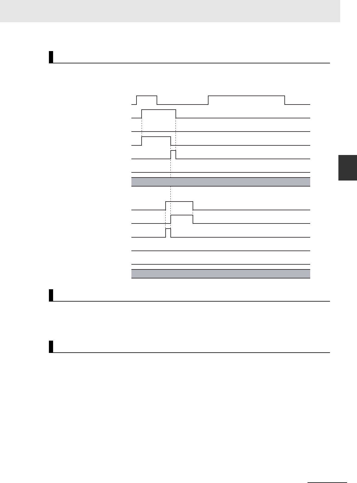
3-361
3 Axis Command Instructions
NJ/NX-series Motion Control Instructions Reference Manual (W508)
MC_AbortTrigger
3
Function
• Done for the MC_AbortTrigger (Disable External Latch) instruction changes to TRUE one period after
Execute changes to TRUE.
This instruction cannot be re-executed.
A Motion Control Instruction Re-execution Disabled error (error code: 543B hex) occurs if re-execution
is attempted.
For details on multi-execution of motion control instructions, refer to the NJ/NX-series CPU Unit Motion
Control User’s Manual (Cat. No. W507) or NY-series Industrial Panel PC / Industrial Box PC Motion
Control User’s Manual (Cat. No. W559).
Timing Charts
Re-execution of Motion Control Instructions
Multi-execution of Motion Control Instructions
16#0000
16#0000
MC_AbortTrigger
Execute
Busy
Done
Command Aborted
Error
ErrorID
MC_TouchProbe
Execute
TriggerInput
Busy
Done
Command Aborted
Error
ErrorID

3 Axis Command Instructions
3-362
NJ/NX-series Motion Control Instructions Reference Manual (W508)
If an error occurs during execution of the MC_AbortTrigger (Disable) instruction. Error will change to
TRUE. You can find out the cause of the error by referring to the value output by ErrorID (Error Code).
Error Codes
Refer to A-1 Error Codes for instruction errors.
Errors
Error code
16#0000
MC_AbortTrigger
Execute
Busy
Done
Command Aborted
Error
ErrorID

3-363
3 Axis Command Instructions
NJ/NX-series Motion Control Instructions Reference Manual (W508)
MC_AxesObserve
3
Variables
MC_AxesObserve
The MC_AxesObserve instruction monitors the deviation between the command position or feedback
position for the specified axis to see if it exceeds the allowed value.
*1 The default value for an enumeration variable is actually not the number, but the enumerator.
*2 The task period is the primary period if the task is the primary periodic task and the task period of the priority-5 periodic
task if the task is the priority-5 periodic task.
*3 Refer to Unit Conversion Settings in the NJ/NX-series CPU Unit Motion Control User's Manual (Cat. No. W507) or NY-
series Industrial Panel PC / Industrial Box PC Motion Control User’s Manual (Cat. No. W559) for information on command
units.
Instruction Name
FB/
FUN
Graphic expression ST expression
MC_AxesObserve Monitor Axis
Following
Error
FB MC_AxesObserve_instance (
Master :=parameter,
Slave :=parameter,
Enable :=parameter,
ReferenceType :=parameter,
PermittedDeviation :=parameter,
Enabled =>parameter,
Invalid =>parameter,
Busy =>parameter,
DeviatedValue =>parameter,
Error =>parameter,
ErrorID =>parameter
);
Variables
Input Variables
Name Meaning Data type Valid range Default Description
Enable Enable BOOL TRUE or FALSE FALSE The instruction is executed
when Enable is TRUE.
ReferenceType Position Type
Selection
_eMC_ RERE-
RENCE_TYPE
0: _mcCommand
1: _mcFeedback
0
*1
Specify the position type.
0: Command position (value
calculated in the previous
task period
*2
)
1: Actual position (value
obtained in the same task
period
*2
)
Permitted
Deviation
Permitted
Following
Error
LREAL Non-negative number 0 Specify the permitted maxi-
mum value of the following
error between the master
and slave axes. The unit is
command units.
*3
MC_AxesObserve_instance
Invalid
Master Master
Slave Slave
Enable Enabled
PermittedDeviation
DeviatedValue
Error
ErrorID
MC_AxesObserve
ReferenceType
Busy

3 Axis Command Instructions
3-364
NJ/NX-series Motion Control Instructions Reference Manual (W508)
*1 Refer to Unit Conversion Settings in the NJ/NX-series CPU Unit Motion Control User's Manual (Cat. No. W507) or NY-
series Industrial Panel PC / Industrial Box PC Motion Control User’s Manual (Cat. No. W559) for information on command
units.
*2 Refer to A-1 Error Codes.
Output Variable Update Timing
* DeviatedValue does not return to FALSE when Enable changes to FALSE.
* Specify a user-defined Axis Variable that was created in the Axis Basic Settings of the Sysmac Studio (default: MC_Axis***)
or a system-defined axis variable name (_MC_AX[*], _MC1_AX[*], or _MC2_AX[*]).
Precautions for Correct UsePrecautions for Correct Use
Assign the master axis and slave axis to the same task. If you specify an axis that is in a different
task as the master axis, an Illegal Master Axis Specification error (error code 5462 hex) occurs.
Output Variables
Name Meaning Data type Valid range Description
Enabled Enable BOOL TRUE or FALSE TRUE when the axis is being controlled.
Invalid Excessive
Following
Error between
Axes
BOOL TRUE or FALSE TRUE when the permitted following error between
axes is exceeded.
Busy Executing BOOL TRUE or FALSE TRUE when the instruction is acknowledged.
DeviatedValue Following
Error between
Axes
LREAL Negative num-
ber, positive
number, or 0
Contains the difference between the specified master
and slave axes. The unit is command units.
*1
Error Error BOOL TRUE or FALSE TRUE while there is an error.
ErrorID Error Code WORD
*2
Contains the error code when an error occurs.
A value of 16#0000 indicates normal execution.
Name Timing for changing to TRUE Timing for changing to FALSE
Enabled When Enable changes to TRUE. • When Error changes to TRUE.
• When Enable changes to FALSE.
Invalid When the permitted following error
between axes is exceeded.
• When Error changes to TRUE.
• When Enable changes to FALSE.
• When the permitted following error between axes is
not exceeded.
Busy When Enable changes to TRUE. • When Error changes to TRUE.
• When Enable changes to FALSE.
DeviatedValue
*
When Enable is TRUE. ---
Error When there is an error in the execution
conditions or input parameters for the
instruction.
When the error is cleared.
In-Out Variables
Name Meaning Data type Valid range Description
Master Master Axis _sAXIS_REF ---
Specify the master axis.
*
Slave Slave Axis _sAXIS_REF ---
Specify the slave axis.
*

3-365
3 Axis Command Instructions
NJ/NX-series Motion Control Instructions Reference Manual (W508)
MC_AxesObserve
3
Function
Additional Information
You can also set axes that belong to groups.
• If the command positions of the specified Master (Master Axis) and Slave (Slave Axis) or the differ-
ence between the actual positions exceeds the permitted following error, Invalid (Excessive Following
Error between Axes) changes to TRUE.
Invalid (Excessive Following Error between Axes) changes to TRUE when the following conditions
are met.
When |DeviatedValue (Following Error between Axes)| > PermittedDeviation (Permitted Following
Error)
• The operation of the axis is not affected by this instruction.
• Use the state of the Invalid (Excessive Following Error between Axes) output variable to program pro-
cesses, such as stopping an axis.
Precautions for Correct UsePrecautions for Correct Use
• Use the same Count Mode for the Master (Master Axis) and Slave (Slave Axis).
If a different mode is set, the axes will be compared in Linear Mode.
Even if both axes are in Rotary Mode, comparisons are made in Linear Mode if the ranges set
for the ring counters are not the same.
• If PermittedDeviation (Permitted Following Error) contains a non-terminating decimal number,
e.g., resulting from division, error may cause unexpected processing results.
• With an NX-series CPU Unit, assign Master (Master Axis) and Slave (Slave Axis) to the same
task. If you assign them to different tasks, an Illegal Master Axis Specification error (error code
5462 hex) occurs for Slave (Slave Axis).
• This function is not effective for monitoring an NX-series Pulse Output Unit because the com-
mand position equals the actual current position.
This section describes the instruction in detail.
ReferenceType (Position Type Selection)
Any of the following position types can be selected for the master axis to which the slave axis is syn-
chronized.
Function
Instruction Details
0
Position
Time
Monitors whether the difference
between master and slave axes
exceeds a specified value.
Slave axis
Master axis

3 Axis Command Instructions
3-366
NJ/NX-series Motion Control Instructions Reference Manual (W508)
• _mcCommand: Command position (value calculated in the previous task period)
The master axis command position that was calculated in the previous task period is used for the
current period.
The command value that was calculated for the master axis in the last periodic task is used to cal-
culate the command position of the slave axis in the current period.
• _mcFeedback: Value obtained in the same task period
The actual position of the master axis that was obtained in the same task period is used.
Precautions for Correct UsePrecautions for Correct Use
Here, the task period is the primary period if the task is the primary periodic task and the task
period of the priority-5 periodic task if the task is the priority-5 periodic task. In the same way, the
periodic task is the primary periodic task or the priority-5 periodic task.
Relationship between Axis Types and Position Types
The relationship between the axis types that you can monitor and position types that is monitored is
shown below.
* A Position Type Selection Out of Range error (error code: 5430 hex) occurs when the instruction is executed.
Calculation Examples for DeviatedValue (Following Error between Axes)
The DeviatedValue (Following Error between Axes) is calculated as described below.
Linear Mode
ReferenceType (Position Type Selection) Set to _mcCommand
DeviatedValue (Following Error between Axes) = Command current position of Master (Master Axis)
− Command current position of Slave (Slave Axis)
ReferenceType (Position Type Selection) Set to _mcFeedback
DeviatedValue (Following Error between Axes) = Actual current position of Master (Master Axis) −
Actual current position of Slave (Slave Axis)
Rotary Mode
ReferenceType (Position Type Selection) Set to _mcCommand
The DeviatedValue (Following Error between Axes) is the shorter distance between the command
current position of the Master (Master Axis) and the command current position of the Slave (Slave
Axis) in the range of the ring counter. The sign of the DeviatedValue (Following Error between Axes)
is the sign for the shorter direction, as given below.
• If the command current position of the Master (Master Axis) is greater than or equal to the com-
mand current position of the Slave (Slave Axis), the value is positive.
• If the command current position of the Master (Master Axis) is less than the command current
position of the Slave (Slave Axis), the value is negative.
Axis type
ReferenceType
_mcCommand _mcFeedback
Servo axis OK OK
Encoder axis
No
*
OK
Virtual servo axes OK OK
Virtual encoder axis
No
*
OK

3-367
3 Axis Command Instructions
NJ/NX-series Motion Control Instructions Reference Manual (W508)
MC_AxesObserve
3
Function
ReferenceType (Position Type Selection) Set to _mcFeedback
The DeviatedValue (Following Error between Axes) is the shorter distance between the actual cur-
rent position of the Master (Master Axis) and the actual current position of the Slave (Slave Axis) in
the range of the ring counter. The sign of the DeviatedValue (Following Error between Axes) is the
sign for the shorter direction, as given below.
• If the actual current position of the Master (Master Axis) is greater than or equal to the actual cur-
rent position of the Slave (Slave Axis), the value is positive.
• If the actual current position of the Master (Master Axis) is less than the actual current position of
the Slave (Slave Axis), the value is negative.
DeviatedValue (Following Error between Axes) Calculation Example in Rotary Mode when Refer-
enceType (Position Type Selection) Is Set to _mcCommand
If ReferenceType (Position Type Selection) is _mcFeedback in Rotary Mode, the “command current
position” in the above diagram would be the “actual current position.”
An error for this instruction does not affect the operation of the axis or axes group. A timing chart is
given below for when PermittedDeviation (Permitted Following Error) is 10.0.
Timing Charts
0
70 100
Slave command current position: −20
Master command current position: 50
Slave command current position: −20
|DeviatedValue| is 70 (because 70 is less than 100).
The sign is positive because the command current position of
the Master is greater than or equal to the command current
position of the Slave, so the DeviatedValue is +70.
Modulo maximum position
setting value: 100
Modulo minimum position
setting value: −70
Slave axis
command position
Master axis
command position
26
0
0001012-23521200000000
20 22 24 28 30 32 34 36 38 40 42 44 46 48 50 52
21 20 24 16 16 32 29 29 15 18 40 42 23 25 28 30 31
Enable
Enabled
Busy
Invalid
Error
Error ID
Deviated Value

3 Axis Command Instructions
3-368
NJ/NX-series Motion Control Instructions Reference Manual (W508)
You cannot re-execute enable-type motion instructions.
There are no restrictions for multi-execution of instructions.
For details on multi-execution of motion control instructions, refer to the NJ/NX-series CPU Unit Motion
Control User’s Manual (Cat. No. W507) or NY-series Industrial Panel PC / Industrial Box PC Motion
Control User’s Manual (Cat. No. W559).
• If an error occurs during instruction execution, Error will change to TRUE.
• You can find out the cause of the error by referring to the value output by ErrorID (Error Code).
• Error information for this instruction is output to Minor Fault in the MC Common motion variable.
Error Codes
Refer to A-1 Error Codes for instruction errors.
Re-execution of Motion Control Instructions
Multi-execution of Motion Control Instructions
Errors
Error code
InValid
Error
ErrorID
Enable
Enabled
Busy

3-369
3 Axis Command Instructions
NJ/NX-series Motion Control Instructions Reference Manual (W508)
MC_SyncMoveVelocity
3
Variables
MC_SyncMoveVelocity
The MC_SyncMoveVelocity instruction outputs the value set for the target velocity every task period to
the Servo Drive in Cyclic Synchronous Velocity Mode.
Precautions for Correct UsePrecautions for Correct Use
• You cannot use this instruction for an NX-series Pulse Output Unit.
• Here, the task period is the primary period if the task is the primary periodic task and the task
period of the priority-5 periodic task if the task is the priority-5 periodic task.
Instruction Name
FB/
FUN
Graphic expression ST expression
MC_SyncMoveVelocity Cyclic
Synchronous
Velocity
Control
FB MC_SyncMoveVelocity_
instance (
Axis :=parameter,
Execute :=parameter,
Velocity :=parameter,
CmdPosMode :=parameter,
BufferMode :=parameter,
InVelocity =>parameter,
Busy =>parameter,
Active =>parameter,
CommandAborted
=>parameter,
Error =>parameter,
ErrorID =>parameter
);
Variables
Input Variables
Name Meaning Data type Valid range Default Description
Execute Execute BOOL TRUE or FALSE FALSE The instruction is executed when
Execute changes to TRUE.
Velocity Target Veloc-
ity
LREAL Negative number,
positive number, or 0
0 Set the target velocity.
0: Set the velocity command value
to 0.
Positive value: Move in the posi-
tive direction.
Negative value: Move in the nega-
tive direction.
The unit is command units/s.
*1
CmdPosMode Command
Current Posi-
tion Count
Selection
_eMC_CMD-
POS_
MODE
0: _mcCount
0
*2
0: Use the actual current position
and update the command current
position.
Home remains defined.
MC_SyncMoveVelocity_instance
Axis Axis
Execute InVelocity
Velocity
BufferMode
Error
ErrorID
CommandAborted
Active
MC_SyncMoveVelocity
CmdPosMode
Busy

3 Axis Command Instructions
3-370
NJ/NX-series Motion Control Instructions Reference Manual (W508)
*1 Refer to Unit Conversion Settings in the NJ/NX-series CPU Unit Motion Control User’s Manual (Cat. No. W507) or NY-
series Industrial Panel PC / Industrial Box PC Motion Control User’s Manual (Cat. No. W559) for information on command
units.
*2 The default value for an enumeration variable is actually not the number, but the enumerator.
* Refer to A-1 Error Codes.
Output Variable Update Timing
BufferMode Buffer Mode
Selection
_eMC_BUFFER_
MODE
0: _mcAborting
1: _mcBuffered
0
*2
Specify the behavior when execut-
ing more than one motion instruc-
tion.
0: Aborting
1: Buffered
Output Variables
Name Meaning Data type Valid range Description
InVelocity Target Veloc-
ity Reached
BOOL TRUE or
FALSE
TRUE when the command velocity reaches the target
velocity.
Busy Executing BOOL TRUE or
FALSE
TRUE when the instruction is acknowledged.
Active Controlling BOOL TRUE or
FALSE
TRUE when control is in progress.
CommandAborted Command
Aborted
BOOL TRUE or
FALSE
TRUE when the instruction is aborted.
Error Error BOOL TRUE or
FALSE
TRUE while there is an error.
ErrorID Error Code WORD * Contains the error code when an error occurs.
A value of 16#0000 indicates normal execution.
Name Timing for changing to TRUE Timing for changing to FALSE
InVelocity When the target velocity is reached. • When Error changes to TRUE.
• When CommandAborted changes to TRUE.
Busy When Execute changes to TRUE. • When Error changes to TRUE.
• When CommandAborted changes to TRUE.
Active When the instruction is started. • When Error changes to TRUE.
• When CommandAborted changes to TRUE.
CommandAborted • When this instruction is canceled due to
another instruction.
• When this instruction is canceled due to
an error in another instruction.
• When this instruction is executed while
there is an axis error.
• When you start this instruction during
MC_Stop instruction execution.
• When Execute is TRUE and changes to FALSE.
• After one period when Execute is FALSE.
Error When there is an error in the execution
conditions or input parameters for the
instruction.
When the error is cleared.
Name Meaning Data type Valid range Default Description

3-371
3 Axis Command Instructions
NJ/NX-series Motion Control Instructions Reference Manual (W508)
MC_SyncMoveVelocity
3
Function
* Specify a user-defined Axis Variable that was created in the Axis Basic Settings of the Sysmac Studio (default: MC_Axis***)
or a system-defined axis variable name (_MC_AX[*], _MC1_AX[*], or _MC2_AX[*]).
• The MC_SyncMoveVelocity instruction outputs the target velocity from the user program every task
period to the Servo Drive in Cyclic Synchronous Velocity (CSV) Control Mode.
• When Execute changes to TRUE, the Control Mode of the Servo Drive is changed and a command
velocity is output.
• If this instruction is executed in the primary periodic task or a priority-5 periodic task, the target veloc-
ity is reached in the next task period.
The following timing charts show an example of the operation for when this instruction is executed in
the primary periodic task. The same information applies when it is used in a priority-5 periodic task.
• If this instruction is executed in the priority-16 periodic task, the target velocity is reached in the next
task period.
Precautions for Correct UsePrecautions for Correct Use
Refer to Precautions for Master and Auxiliary Axes in Synchronized Control on page 1-6 for pre-
cautions on using this instruction for the master axis of synchronized control.
Additional Information
The MC_SetOverride (Set Override Factors) instruction is not effective for the MC_SyncMoveVe-
locity (Cyclic Synchronous Velocity Control) instruction.
In-Out Variables
Name Meaning Data type Valid range Description
Axis Axis _sAXIS_REF ---
Specify the axis.
*
Function
M
E
MC_SyncMoveVelocity Programmed in Primary Periodic Task
Command
velocity
Time
Primary period
Velocity
Servo
Drive
Target velocity (black dots)
specified with the input
Command
velocity
M
E
MC_SyncMoveVelocity Programmed in Priority-16 Periodic Task
Command
velocity
Time
Primary period
Command
velocity
Velocity
Servo
Drive
Task period
Target velocity (black dots)
specified with the input

3 Axis Command Instructions
3-372
NJ/NX-series Motion Control Instructions Reference Manual (W508)
Mapping Data Objects
To use the MC_SyncMoveVelocity (Cyclic Synchronous Velocity Control) instruction, map the follow-
ing object data in the Detailed Settings Area of the Axis Basic Settings Display of the Sysmac Stu-
dio.
• Target velocity (60FF hex)
• Modes of operation (6060 hex)
• Modes of operation display (6061 hex)
If even one of the required objects is not set, a Process Data Object Setting Missing error (error
code 3461 hex) occurs.
For details on mapping data objects, refer to 2-3 PDO Mapping and to the NJ/NX-series CPU Unit
Motion Control User’s Manual (Cat. No. W507) or NY-series Industrial Panel PC / Industrial Box PC
Motion Control User’s Manual (Cat. No. W559).
This section describes the instruction in detail.
Velocity (Target Velocity)
The Velocity (Target Velocity) input variable can be set to LREAL data in reference to 0.
The axis moves in the positive direction for a positive value and in the negative direction for a nega-
tive value.
If 0 is set, the command velocity is 0 and Status.Continuous (Continuous Motion) remains TRUE.
You can set Velocity (Target Velocity) from the user program every period.
If the specified target velocity is different from the last period, the new target velocity is used. If the
specified target velocity is the same as the last period, the previous target velocity is used.
Precautions for Correct UsePrecautions for Correct Use
• When you set the target velocity, make sure that an excessive load is not placed on the
mechanical composition of the system for the change in velocity.
• If the axis that you use in this instruction is the master axis for synchronized control, setting the
target velocity of the master axis may cause the slave axis to move suddenly.
• When the Control Mode is changed, the command current position may change suddenly.
Instruction Details

3-373
3 Axis Command Instructions
NJ/NX-series Motion Control Instructions Reference Manual (W508)
MC_SyncMoveVelocity
3
Function
Command Current Position
If you select _mcCount for the CmdPosMode (Command Current Position Count Selection) input
variable, the command current position will be the actual current position from the previous period
when this instruction is executed. The actual current position is used until the instruction is ended.
While the OMRON 1S-series Servo Drive or G5-series Servo Drive is processing the switch to CSP
Mode, the CSP reference position that was mapped in advance is sent in the PDO. Until processing
to switch from CSV to CSP Mode is completed, this reference position is used as the command cur-
rent position. When switching to CSP Mode is completed, the command current position is set to the
command position.
When Using an OMRON 1S-series Servo Drive
To use the CSP reference position of the Servo Drive when changing the Control Mode, map the
CSP Reference Position (3010-87 hex) to process data.
Map the CSP Reference Position (3010-87 hex) to process data in the PDO Edit Tab Page of the
Sysmac Studio. Then map the CSP Change Reference Position in the MC Function Module and the
CSP Reference Position (3010-87 hex) in the Detailed Settings Area of the Axis Basic Settings Dis-
play.
When Using an OMRON G5-series Servo Drive
To use the CSP reference position of the Servo Drive when changing the Control Mode, map the
CSP Reference Position (4020 hex) to process data. Map the CSP Reference Position (4020 hex) to
process data in the PDO Edit Tab Page of the Sysmac Studio. Then map the CSP Change Refer-
ence Position in the MC Function Model and the CSP Reference Position (4020 hex) in the Detailed
Settings Area of the Axis Basic Settings Display.
Precautions for Correct UsePrecautions for Correct Use
If the CSP Reference Position (4020 hex) is mapped to a PDO, set the primary period or the task
period of the priority-5 periodic task to 1 ms or longer. If the primary period or task period is less
than 1 ms, an error will occur in the G5-series Servo Drive. Refer to the AC Servomotors/Servo
Drives G5-series with Built-in EtherCAT Communications User’s Manual (Cat. No. I576) for
details.
Additional Information
Of the OMRON G5-series Servo Drives, those for Linear Motors do not support the CSP Refer-
ence Position (4020 hex).
Actual current
position is used.
Servo Drive CSP
reference position
Command
current position
Time
Changing
the Control
Mode
CSP CSPCSV

3 Axis Command Instructions
3-374
NJ/NX-series Motion Control Instructions Reference Manual (W508)
When Using a Servo Drive Other Than an OMRON 1S-series Servo Drive or
G5-series Servo Drive
An error may occur in processing to switch the Control Mode for some Servo Drives when this
instruction is executed or when an instruction that uses CSP Mode is executed during execution of
this instruction.
If that occurs, stop the axis (velocity of 0) and then execute this instruction or use multi-execution of
instructions that use the CSP Mode.
When Using NX-series Position Interface Units
You cannot use this instruction for NX-series Position Interface Units.
Stop Processing
The Control Mode and command velocities that are used to stop axis motion are described below.
For a deceleration stop, the target velocity of this instruction is used as the initial velocity and the
axis is decelerated to a stop with the deceleration rate for the specified Stop Mode.
Stopping with the MC_ImmediateStop Instruction
The command velocity is changed to 0. The Control Mode is changed to CSP Mode when the
change criterion that is given below is satisfied.
Stopping with the MC_Stop Instruction
The command velocity is changed to 0 at the deceleration rate of the instruction. The Control Mode
is changed to CSP Mode when the change criterion that is given below is satisfied.
Stopping for a Minor Fault Level Error
The command velocity is changed to 0 at the deceleration rate of each error. The Control Mode is
changed to CSP Mode when the change criterion that is given below is satisfied.
Stopping for a Major Fault Level Error or a Partial Fault Level Error
The command velocity is changed to 0. The Control Mode is changed to CSP Mode when the
change criterion that is given below is satisfied.
However, depending on the error level, it may not be possible to switch the Control Mode normally,
and the axis may stop in CSV Mode.
Stopping by Turning OFF the Servo
The command velocity is changed to 0 with the specified method. The Control Mode is not changed.
Stopping When the Operating Mode of the CPU Unit Changes to PROGRAM
Mode
The command velocity is changed to 0 with the specified method. The Control Mode is changed to
CSP Mode when the change criterion that is given below is satisfied.
Change Criterion
Whether it is possible to change the Control Mode depends on Servo Drive specifications.
To ensure that the Control Mode is switched to CSP Mode during stop processing for stop instruc-
tions or errors, it is necessary to sufficiently decelerate the Servomotor first.
The Control Mode is changed to CSP Mode when the following criterion is met for three consecutive
periodic tasks after the command velocity changes to 0.
Actual current velocity ≤ Maximum velocity × 0.1

3-375
3 Axis Command Instructions
NJ/NX-series Motion Control Instructions Reference Manual (W508)
MC_SyncMoveVelocity
3
Function
Precautions for Correct UsePrecautions for Correct Use
Here, the periodic task is the primary periodic task or the priority-5 periodic task.
Recovery to Cyclic Synchronous Position (CSP) Control Mode
It is not always possible to normally change to CSP Mode for a stop.
For example, it may not be possible when a partial fault level error occurs in the MC Function Mod-
ule.
Therefore, processing to change to CSP Mode is performed when the Status output variable from
the MC_Power (Power Servo) instruction changes to FALSE.
Operation for Failure to Switch Control Mode
If the Servo Drive does not complete switching the Control Mode within 1 second after a Control
Mode switch command is sent to the Servo Drive, a Error in Changing Servo Drive Control Mode
(error code: 7439 hex) occurs.
Also, if the switching criterion is not met within 10 seconds after the command velocity is changed to
0 for a Control Mode switching command to the Servo Drive, an Error in Changing Servo Drive Con-
trol Mode (error code: 7439 hex) occurs.
When an Error in Changing Servo Drive Control Mode (error code: 7439 hex) occurs, the command
velocity is changed to 0 and the Servo is turned OFF (free-run stop).
For details on the Error in Changing Servo Drive Control Mode (error code: 7439 hex), refer to the
NJ/NX-series CPU Unit Motion Control User’s Manual (Cat. No. W507) or NY-series Industrial Panel
PC / Industrial Box PC Motion Control User’s Manual (Cat. No. W559).
Applicable Axes and Execution Condition
• You can use this instruction for a servo axis.
To use this instruction, change Enable for the MC_Power instruction to TRUE (Servo ON).
• A virtual servo axis will acknowledge this instruction at any time.
However, processing to switch the Control Mode of the Servo Drive is not performed.
• An error occurs if the instruction is executed for an encoder or virtual encoder axis.
Axis Variable Status
Status.Continuous (Continuous Motion) in the Axis Variable status changes to TRUE.
Use DrvStatus (Servo Drive Status) in the Axis Variable to check the Control Mode that is set in the
Servo Drive. The Servo Drive status is given in the following table.
Home Status
If CmdPosMode (Command Current Position Count Selection) is set to _mcCount, the home will
remain defined.
Overrides
Overrides are disabled for this instruction.
Name Data type Meaning Description
CSP BOOL Cyclic Synchronous Position (CSP) Con-
trol Mode
TRUE when the Servo is ON and the
Servo Drive is in CSP Mode.
CSV BOOL Cyclic Synchronous Velocity (CSV) Con-
trol Mode
TRUE when the Servo is ON and the
Servo Drive is in CSV Mode.
CST BOOL Cyclic Synchronous Torque (CST) Control
Mode
TRUE when the Servo is ON and the
Servo Drive is in CST Mode.

3 Axis Command Instructions
3-376
NJ/NX-series Motion Control Instructions Reference Manual (W508)
Software Limits
Software limits are enabled for this instruction. These are enabled even for the following axis param-
eter settings.
• Deceleration stopping enabled for command position
• Immediate stopping enabled for command position (stop using remaining pulses)
• Busy (Executing) changes to TRUE at the same time as Execute changes to TRUE. Active (Con-
trolling) changes to TRUE in the next period.
• InVelocity (Target Velocity Reached) changes to TRUE when the command velocity reaches Velocity
(Target Velocity).
• If another instruction aborts this instruction, CommandAborted changes to TRUE and Busy (Execut-
ing), Active (Controlling), and InVelocity (Target Velocity Reached) change to FALSE.
• The MC_Stop instruction is used to stop this instruction.
The following timing charts show operation for when this instruction is used in the primary periodic task.
Timing Charts
Busy
InVelocity
CommandAborted
Active
Error
16#0000
ErrorID
Execute
Busy
Done
Active
Execute
CSP CSV CSP CSV
Velocity
Time
MC_SyncMoveVelocity Instruction
MC_Stop Instruction
Control Mode
Target velocity
Switched. Switched. Switched.
Decelerates to a
stop when MC_Stop
is executed.
Target velocity is
changed each
primary period.
The target
velocity does
not change.

3-377
3 Axis Command Instructions
NJ/NX-series Motion Control Instructions Reference Manual (W508)
MC_SyncMoveVelocity
3
Function
Additional Information
The MC Function Module sends a command to the Servo Drive to change the Control Mode as
shown in the above timing chart. The timing of implementing the change in the Servo Drive
depends on Servo Drive specifications.
This instruction cannot be re-executed.
A Motion Control Instruction Re-execution Disabled error (error code: 543B hex) occurs if re-execution
is attempted.
For details on multi-execution of motion control instructions, refer to the NJ/NX-series CPU Unit Motion
Control User's Manual (Cat. No. W507) or NY-series Industrial Panel PC / Industrial Box PC Motion
Control User’s Manual (Cat. No. W559).
Execution during Execution of Other Instructions
You can execute this instruction with BufferMode (Buffer Mode Selection) set to Aborting or Buffered
during execution of other instructions in the same as for the MC_MoveVelocity (Velocity Control)
instruction.
The Control Mode is switched when processing the instruction is started.
For details on BufferMode (Buffer Mode Selection), refer to the NJ/NX-series CPU Unit Motion Con-
trol User's Manual (Cat. No. W507) or NY-series Industrial Panel PC / Industrial Box PC Motion Con-
trol User’s Manual (Cat. No. W559).
Execution of Other Instructions during Instruction Execution
You can execute other instructions with BufferMode (Buffer Mode Selection) set to Aborting or Buff-
ered during execution of this instruction in the same as for the MC_MoveVelocity (Velocity Control)
instruction.
If the other instruction is buffered, then it is executed when InVelocity (Target Velocity Reached)
changes to TRUE.
The Control Mode is switched when processing the instruction is started.
Re-execution of Motion Control Instructions
Multi-execution of Motion Control Instructions

3 Axis Command Instructions
3-378
NJ/NX-series Motion Control Instructions Reference Manual (W508)
If an error occurs during instruction execution, Error will change to TRUE and the axis will stop.
You can find out the cause of the error by referring to the value output to ErrorID (Error Code).
Timing Chart When Error Occurs
Error Codes
Refer to A-1 Error Codes for instruction errors.
Errors
Busy
CommandAborted
InVelocity
Error
16#0000
ErrorID
Execute
Active
Error code

3-379
3 Axis Command Instructions
NJ/NX-series Motion Control Instructions Reference Manual (W508)
MC_SyncMoveAbsolute
3
Variables
MC_SyncMoveAbsolute
The MC_SyncMoveAbsolute instruction cyclically outputs the specified target position for the axis.
Version Information
A CPU Unit with unit version 1.03 or later and Sysmac Studio version 1.04 or higher are required
to use this instruction.
*1 Refer to Unit Conversion Settings in the NJ/NX-series CPU Unit Motion Control Use’s Manual (Cat. No. W507) or NY-
series Industrial Panel PC / Industrial Box PC Motion Control User’s Manual (Cat. No. W559) for information on command
units.
*2 The default value for an enumeration variable is actually not the number, but the enumerator.
*3 Refer to Direction for the MC_MoveAbsolute instruction (page 3-49) for how to specify the direction of rotation.
Instruction Name
FB/
FUN
Graphic expression ST expression
MC_SyncMove
Absolute
Cyclic Syn-
chronous
Absolute
Positioning
FB MC_SyncMoveAbsolute_instance (
Axis :=parameter,
Execute :=parameter,
Position :=parameter,
Direction :=parameter,
BufferMode :=parameter,
InPosition =>parameter,
Busy =>parameter,
Active =>parameter,
CommandAborted =>parameter,
Error =>parameter,
ErrorID =>parameter
);
Variables
Input Variables
Name Meaning Data type Valid range Default Description
Execute Execute BOOL TRUE or FALSE FALSE The instruction is executed when
Execute changes to TRUE.
Position Target
Position
LREAL Negative number, posi-
tive number, or 0
0 Specify the absolute target position.
The unit is command units.
*1
Direction Direction _eMC_DIREC-
TION
0: _mcPositiveDirection
1: _mcShortestWay
2: _mcNegativeDirection
3: _mcCurrentDirection
4: _mcNoDirection
1
*2
Specify the direction of rotation
when the Count Mode is Rotary
Mode.
*3
0: Positive direction
1: Shortest way
2: Negative direction
3: Current direction
4: No direction specified
BufferMode Buffer
Mode
Selection
*2
_eM-
C_BUFFER_-
MODE
0: _mcAborting
0
*3
Specify the behavior when executing
more than one motion instruction.
0: Aborting
MC_SyncMoveAbsolute_instance
Axis Axis
Execute InPosition
Position
BufferMode
Error
ErrorID
CommandAborted
Active
MC_SyncMoveAbsolute
Direction
Busy

3 Axis Command Instructions
3-380
NJ/NX-series Motion Control Instructions Reference Manual (W508)
* Refer to A-1 Error Codes.
Output Variable Update Timing
* Specify a user-defined Axis Variable that was created in the Axis Basic Settings of the Sysmac Studio (default: MC_Axis***)
or a system-defined axis variable name (_MC_AX[*], _MC1_AX[*], or _MC2_AX[*]).
Output Variables
Name Meaning Data type Valid range Description
InPosition In Position BOOL TRUE or FALSE
TRUE when the actual current position is within
the in-position range of the target position.
Busy Executing BOOL TRUE or FALSE TRUE when the instruction is acknowledged.
Active Controlling BOOL TRUE or FALSE TRUE when control is in progress.
CommandAborted Instruction
Aborted
BOOL TRUE or FALSE TRUE when the instruction is aborted.
Error Error BOOL TRUE or FALSE TRUE while there is an error.
ErrorID Error Code WORD
*
Contains the error code when an error occurs.
A value of 16#0000 indicates normal execution.
Name Timing for changing to TRUE Timing for changing to FALSE
InPosition When the actual current position is within the in-
position range of the target position.
• When an actual current position is outside of
the in-position range.
• When Error changes to TRUE.
• When CommandAborted changes to TRUE.
Busy When Execute changes to TRUE. • When Error changes to TRUE.
• When CommandAborted changes to TRUE.
Active When the instruction is started. • When Error changes to TRUE.
• When CommandAborted changes to TRUE.
CommandAborted • When this instruction is aborted because
another motion control instruction was exe-
cuted with the Buffer Mode set to Aborting.
• When this instruction is canceled due to an
error in another instruction.
• When this instruction is executed while there is
an axis error.
• When you start this instruction during MC_Stop
instruction execution.
• When Execute is TRUE and changes to
FALSE.
• After one period when Execute is FALSE.
Error When there is an error in the execution conditions
or input parameters for the instruction.
When the error is cleared.
In-Out Variables
Name Meaning Data type
Valid
range
Description
Axis Axis _sAXIS_REF --- Specify the axis. *

3-381
3 Axis Command Instructions
NJ/NX-series Motion Control Instructions Reference Manual (W508)
MC_SyncMoveAbsolute
3
Function
• The MC_GroupSyncMoveAbsolute instruction outputs the target position from the user program
every task period to the Servo Drive or other device in Cyclic Synchronous Position (CSP) Control
Mode. The target position is given as an absolute position.
• The upper limit of the velocity is the value that is set in the Maximum Velocity axis parameter. The
maximum acceleration and deceleration rates are not used.
• If this instruction is executed in the primary periodic task or priority-5 periodic task, the target position
that is specified in the input parameters is output to the Servo Drive in the next task period.
The following timing charts show an example of the operation for when this instruction is executed in
the primary periodic task. The same information applies when it is used in a priority-5 periodic task.
• If this instruction is executed in the priority-16 periodic task, the target position that is specified in the
input parameters is output to the Servo Drive in the next periodic task.
Precautions for Correct UsePrecautions for Correct Use
Specify the target position so that the travel distance to the target position does not cause the
velocity to exceed the value that is specified in the Maximum Velocity axis parameter. If a target
position is specified that cause the maximum velocity to be exceeded, the command velocity will
become saturated and the travel distance will be output so that the maximum velocity is not
exceeded. If this occurs, any insufficient travel distance to the target position is output in the next
period or later. Details.VelLimit (Command Velocity Saturation) in the axis control status changes
to TRUE at this time.
This section describes the instruction in detail.
In-position Check
If Position (Target Position) is not changed, InPosition changes to TRUE when the difference between
the target position and the actual position is within the range that is set for the In-position Range axis
parameter.
Function
Instruction Details
M
E
MC_SyncMoveAbsolute Executed in Primary Periodic Task
Command
position
Time
Primary period
Command
position
Position
Servo
Drive
Target positions (black
dots) specified with the
input parameters
M
E
MC_SyncMoveAbsolute Executed in Priority-16 Periodic Task
Command
position
Time
Primary period
Command
position
Position
Servo
Drive
Task period
Target positions (black
dots) specified with
the input parameters

3 Axis Command Instructions
3-382
NJ/NX-series Motion Control Instructions Reference Manual (W508)
Even if the target position is changed while InPosition is TRUE, it will remain TRUE for the remainder of
the period and change to FALSE the next period.
The setting of the In-position Check Time axis parameter is disabled.
Stop Processing
This section describes the methods that are used to stop axis operations.
Use the MC_Stop or MC_ImmediateStop instruction to stop operation. If one of these instructions is
executed, CommandAborted for this instruction will change to TRUE.
Stopping with the MC_Stop Instruction
An immediate stop is performed.
Stopping with the MC_ImmediateStop Instruction
An immediate stop is performed according to the setting of the Immediate Stop Input Stop Method
axis parameter.
Stopping Due to Errors
If an error that causes the axes to stop occurs, an immediate stop is performed regardless of any
settings.
Applicable Axes
• You can use this instruction for a servo axis.
To use this instruction, change Enable for the MC_Power instruction to TRUE (Servo ON).
• A virtual servo axis will acknowledge this instruction at any time.
• An error occurs if the instruction is executed for an encoder or virtual encoder axis.
Axis Variable Status
Status.Discrete (Discrete Motion) in the axis status in the Axis Variable changes to TRUE.
The Axis Control Status is not affected.
Overrides
Overrides are disabled for this instruction.
Changing the Actual Position
When the actual position is changed with the MC_SetPosition instruction, the travel distance from the
new actual position to the target position that is specified for Position (Target Position) is output. If InPo-
sition is TRUE before the actual position is changed, it will change to FALSE the next period after it is
changed.

3-383
3 Axis Command Instructions
NJ/NX-series Motion Control Instructions Reference Manual (W508)
MC_SyncMoveAbsolute
3
Function
• Busy (Executing) changes to TRUE at the same time as Execute changes to TRUE. Active (Con-
trolling) changes to TRUE in the next period.
• InPosition changes to TRUE when the actual current position is within the in-position range from
Position (Target Position).
• If another instruction aborts this instruction, CommandAborted changes to TRUE and Busy (Execut-
ing), Active (Controlling), and InPosition change to FALSE.
• The MC_Stop instruction is used to stop this instruction.
The following timing charts show operation for when this instruction is executed in the primary periodic
task.
Additional Information
The MC Function Module sends a command to the Servo Drive to change the Control Mode as
shown in the above timing chart. The timing of implementing the change in the Servo Drive
depends on Servo Drive specifications.
Timing Charts
Busy
InPosition
Position
CommandAborted
Active
Error
ErrorID
Execute
Active
Busy
Done
60
50
40
30
20
0
Execute
20 30 40 50 60 40
16#0000
Command position
Time
MC_SyncMoveAbsolute instruction
MC_Stop Instruction

3 Axis Command Instructions
3-384
NJ/NX-series Motion Control Instructions Reference Manual (W508)
This instruction cannot be re-executed.
A Motion Control Instruction Re-execution Disabled error (error code: 543B hex) occurs if re-execution
is attempted.
For details on multi-execution of instructions, refer to the NJ/NX-series CPU Unit Motion Control User’s
Manual (Cat. No. W507) or NY-series Industrial Panel PC / Industrial Box PC Motion Control User’s
Manual (Cat. No. W559).
Execution during Execution of Other Instructions
You can switch to this instruction or buffer this instruction if you execute it during execution of another
instruction.
You can buffer one instruction per axis.
Specify the operation of this instruction using BufferMode (Buffer Mode Selection) for multi-execution of
instructions.
For details on BufferMode (Buffer Mode Selection), refer to the NJ/NX-series CPU Unit Motion Control
User’s Manual (Cat. No. W507) or NY-series Industrial Panel PC / Industrial Box PC Motion Control
User’s Manual (Cat. No. W559).
Execution of Other Instructions during Instruction Execution
If you execute another instruction during execution of this instruction, you can specify only aborting.
Re-execution of Motion Control Instructions
Multi-execution of Motion Control Instructions
Buffer Mode Selec-
tion
Description
Aborting Aborts the instruction being executed and switches to this instruction.
If the direction of axis motion is reversed by switching instructions, the motion will be
reversed according to the Operation Selection at Reversing axis parameter.

3-385
3 Axis Command Instructions
NJ/NX-series Motion Control Instructions Reference Manual (W508)
MC_SyncMoveAbsolute
3
Function
If an error occurs during instruction execution, Error will change to TRUE and the axes will stop.
You can find out the cause of the error by referring to the value output by ErrorID (Error Code).
Timing Chart When Error Occurs
Error Codes
Refer to A-1 Error Codes for instruction errors.
Errors
Busy
CommandAborted
InPosition
Error
16#0000
ErrorID
Execute
Active
Error code

3 Axis Command Instructions
3-386
NJ/NX-series Motion Control Instructions Reference Manual (W508)
MC_Reset
The MC_Reset instruction clears axis errors.
* Refer to A-1 Error Codes.
Instruction Name FB/FUN Graphic expression ST expression
MC_Reset Reset Axis
Error
FB MC_Reset_instance (
Axis :=parameter,
Execute :=parameter,
Done =>parameter,
Busy =>parameter,
Failure =>parameter,
Error =>parameter,
ErrorID =>parameter
);
Variables
Input Variables
Name Meaning Data type Valid range Default Description
Execute Execute BOOL TRUE or FALSE FALSE The instruction is executed
when Execute changes to
TRUE.
Output Variables
Name Meaning Data type Valid range Description
Done Done BOOL TRUE or
FALSE
TRUE when the instruction is completed.
Busy Executing BOOL TRUE or
FALSE
TRUE when the instruction is acknowledged.
Failure Failure End BOOL TRUE or
FALSE
TRUE when the instruction is not executed normally.
Error Error BOOL TRUE or
FALSE
TRUE while there is an error.
ErrorID Error Code WORD
*
Contains the error code when an error occurs.
A value of 16#0000 indicates normal execution.
MC_Reset_instance
Failure
Axis Axis
Execute
Error
ErrorID
MC_Reset
Done
Busy

3-387
3 Axis Command Instructions
NJ/NX-series Motion Control Instructions Reference Manual (W508)
MC_Reset
3
Function
Output Variable Update Timing
* Specify a user-defined Axis Variable that was created in the Axis Basic Settings of the Sysmac Studio (default: MC_Axis***)
or a system-defined axis variable name (_MC_AX[*], _MC1_AX[*], or _MC2_AX[*]).
• The MC_Reset instruction starts error clear processing for the axis specified by Axis when Execute
changes to TRUE. The error processing resets axis errors and, if errors have occurred in the Servo
Drive, drive errors.
• You can use this instruction for any axis type.
• Error clear processing is executed only for axes with errors.
• If there is a drive error for an axis, the drive error is cleared first. Error clear processing is then per-
formed. Reset processing for the drive error is continued until the drive error is cleared or continues
for the Drive Error Reset Monitoring Time in the axis parameters.
• If this instruction is executed while the axis is decelerating to a stop for an error, the instruction is not
executed and Failure will change to TRUE. Failure will also change to TRUE if an axis error that
results from an MC common error cannot be cleared by this instruction. This is to ensure that the
error is not reset before the axis stops.
MC Common errors include MC Common Partial Faults and MC Common Minor Faults.
• Only errors that existed when Execute changes to TRUE are cleared. Errors that occur while clearing
errors are not cleared.
Name Timing for changing to TRUE Timing for changing to FALSE
Done When error clear processing is completed
normally.
• When Execute is TRUE and changes to FALSE.
• After one period when Execute is FALSE.
Busy When Execute changes to TRUE. • When Done changes to TRUE.
• When Error changes to TRUE.
• When Failure changes to TRUE.
Failure • When an error reset is executed while
decelerating an axis to a stop for an
error.
• When an error reset is executed during
an axis error for an axis common error.
• When Execute is TRUE and changes to FALSE.
• After one period when Execute is FALSE.
Error When there is an error in the execution
conditions or input parameters for the
instruction.
When the error is cleared.
In-Out Variables
Name Meaning Data type Valid range Description
Axis Axis _sAXIS_REF ---
Specify the axis.
*
Function

3 Axis Command Instructions
3-388
NJ/NX-series Motion Control Instructions Reference Manual (W508)
Precautions for Correct UsePrecautions for Correct Use
• The error clear processing that is performed by this instruction sometimes requires more than
one control period.
• If an MC Common Partial Fault or MC Common Minor Fault occurs or the axis is in motion,
Failure (Failure End) from the instruction will change to TRUE. Remove the cause of the error,
and then retry the process until Done changes to TRUE.
• After you remove the cause of the error, execute the instruction only after you confirm that the
axes have stopped completely.
Act.Vel (Actual Current Velocity) in the Axis Variable is 0 if the axis is completely stopped. Use
this to confirm when the axis is completely stopped.
• If you use this instruction for an OMRON G5-series Servo Drive, perform exclusive control of
instructions so that the ResetECError (Reset EtherCAT Error) instruction is not executed at the
same time.
• If this instruction is used for an NX-series Pulse Output Unit, the error in the Servo Drive that is
connected to the Pulse Output Unit is not reset. Refer to the NX-series Position Interface Units
User’s Manual (Cat. No. W524) for details.
Additional Information
The following errors cannot be cleared with this instruction.
• All axis common errors: Execute the ResetMcError (Reset All Errors) instruction.
• All axes group errors: Execute the MC_GroupReset (Group Reset) instruction.
The causes of network errors, such as slave communications error, are not cleared by executing
MC_Reset. Execute the ResetECATError instruction.
Timing Charts
#0000
Busy
Error
ErrorID
Execute
Busy
Done
Failure
Error code
Output parameters during errors

3-389
3 Axis Command Instructions
NJ/NX-series Motion Control Instructions Reference Manual (W508)
MC_Reset
3
Function
The instruction is aborted if it is not possible to clear errors that occur when the axis is decelerating to a
stop for an error or errors that occur during axis errors resulting from axis common errors.
Refer to A-1 Error Codes for instruction errors.
Aborting the Instruction
Error Codes
Error
ErrorID
Execute
Busy
Done
Error
Failure
Error code
Output parameters during errors

3 Axis Command Instructions
3-390
NJ/NX-series Motion Control Instructions Reference Manual (W508)
MC_ChangeAxisUse
The MC_ChangeAxisUse instruction temporarily changes the Axis Use axis parameter.
Precautions for Correct UsePrecautions for Correct Use
The values that are written by this instruction are not saved in non-volatile memory in the CPU
Unit. Any values that are written are lost when the power supply to the Controller is turned OFF,
when settings are downloaded, or when the MC Function Module is restarted. They return to the
values that were set from the Sysmac Studio. Use the Sysmac Studio and transfer the parame-
ters to save them to non-volatile memory.
Additional Information
• Use the Synchronize Menu of the Sysmac Studio to download the project.
• Refer to the NJ/NX-series CPU Unit Software User’s Manual (Cat. No. W501) or NY-series
Industrial Panel PC / Industrial Box PC Software User’s Manual (Cat. No. W558) for an appli-
cation example that uses this instruction.
Version Information
A CPU Unit with unit version 1.04 or later and Sysmac Studio version 1.05 or higher are required
to use this instruction.
* The default value for an enumeration variable is actually not the number, but the enumerator.
Instruction Name FB/FUN Graphic expression ST expression
MC_ChangeAxisUse Change
Axis Use
FB MC_ChangeAxisUse_instance (
Axis :=parameter,
Execute :=parameter,
AxisUse :=parameter,
Done =>parameter,
Busy =>parameter,
CommandAborted =>parameter,
Error =>parameter,
ErrorID =>parameter
);
Variables
Input Variables
Name Meaning Data type Valid range Default Description
Execute Execute BOOL TRUE or FALSE FALSE The instruction is executed
when Execute changes to
TRUE.
AxisUse Axis Use _eMC_AXIS_USE 1: _mcUnusedAxis
2: _mcUsedAxis
1* Specify a used axis or an
unused axis.
1: Unused axis
2: Used axis
MC_ChangeAxisUse_instance
Axis Axis
Execute Done
AxisUse Busy
Error
ErrorID
MC_ChangeAxisUse
CommandAborted

3-391
3 Axis Command Instructions
NJ/NX-series Motion Control Instructions Reference Manual (W508)
MC_ChangeAxisUse
3
Function
*Refer to A-1 Error Codes.
Output Variable Update Timing
* Specify a user-defined Axis Variable that was created in the Axis Basic Settings of the Sysmac Studio (default: MC_Axis***)
or a system-defined axis variable name (_MC_AX[*], _MC1_AX[*], or _MC2_AX[*]).
• When Execute changes to TRUE, the MC_ChangeAxisUse instruction temporarily changes the Axis
Use axis parameter to the specified setting.
• When execution of the instruction is completed, _MC_AX[*].Cfg.AxEnable (Axis Use) in the Axis Vari-
able changes to the specified setting.
• You can change the setting only for axes that have the Axis Use axis parameter set to Unused axis
(changeable to used axis) or Used axis. You cannot change the setting of the Axis Use axis parame-
ter to specify a used axis if that axis is set to Unused axis (unchangeable to used axis).
• You can execute this instruction when home is defined or when home is not defined. If home is
defined and the axis is changed to an unused axis, the home definition is lost.
• If you change an axis that uses an absolute encoder from a used axis to an unused axis, the absolute
encoder home offset value (which is saved to the battery-backup memory in the CPU Unit when the
power supply to the Controller is turned OFF) will be the value from just before the axis was changed
to an unused axis.
Output Variables
Name Meaning Data type Valid range Description
Done Done BOOL TRUE or
FALSE
TRUE when the instruction is completed.
Busy Executing BOOL TRUE or
FALSE
TRUE when the instruction is acknowledged.
CommandAborted Command
Aborted
BOOL TRUE or
FALSE
TRUE when the instruction is aborted.
Error Error BOOL TRUE or
FALSE
TRUE while there is an error.
ErrorID Error Code WORD
*
Contains the error code when an error occurs.
A value of 16#0000 indicates normal execution.
Name Timing for changing to TRUE Timing for changing to FALSE
Done When the instruction is completed. • When Execute is TRUE and changes to FALSE.
• After one period when Execute is FALSE.
Busy When Execute changes to TRUE. • When Done changes to TRUE.
• When Error changes to TRUE.
• When CommandAborted changes to TRUE.
CommandAborted When this instruction is canceled due to an
error in another instruction.
• When Execute is TRUE and changes to FALSE.
• After one period when Execute is FALSE.
Error When there is an error in the execution
conditions or input parameters for the
instruction.
When the error is cleared.
In-Out Variables
Name Meaning Data type Valid range Description
Axis Axis _sAXIS_REF ---
Specify the axis.
*
Function

3 Axis Command Instructions
3-392
NJ/NX-series Motion Control Instructions Reference Manual (W508)
Precautions for Correct UsePrecautions for Correct Use
• You cannot change an axis to a used axis if the axis number exceeds the highest axis number
that can be controlled by the CPU Unit. The number of real axes that you can change to used
axes is the maximum number of used real axes.
• Either _MC_AX[*].Status.Disabled (Axis Disabled) or _MC_AX[*].Status.Standstill (Standstill)
in the Axis Variable must be TRUE to execute this instruction. If both of them are FALSE, an
error will occur when you execute the instruction.
• An error will occur if you execute this instruction when _MC_AX[*].Details.VelLimit (Command
Velocity Saturation) in the Axis Variable is TRUE.
• If the Axis Use variable of an axis is set to _mcUnusedAxis (unused axis), you cannot over-
write the axis parameter settings with the MC_Write (Write MC Setting) instruction. Change
the Axis Use variable of the axis to _mcUsedAxis (used axis) before you execute the
MC_Write (Write MC Setting) instruction.
• An error occurs if you execute the MC_GroupEnable (Enable Axes Group) instruction for an
axes group that contains an axis that was changed to an unused axis with this instruction.
• If an error occurs in executing this instruction for a used axis, an axis error will occur. If an error
occurs in executing this instruction for an unused axis, an MC common error will occur.
• After you change axis usage with this instruction, make sure that the Done output variable
from this instruction is TRUE before you execute any other motion control instructions.
Additional Information
For an NX-series CPU Unit, a variable name that starts with _MC_AX[*] may start with
_MC1_AX[*] or _MC2_AX[*] instead.
Item NX701-17 NX701-16
Settable axis numbers 0 to 255 0 to 127
Maximum number of used real axes 256 axes 128 axes
Item NX1P2-11 NX1P2-10 NX1P2-90
Settable axis numbers 0 to 11 0 to 9 0 to 3
Maximum number of used real axes 8 axes 6 axes 4 axes
Used motion control servo
axes
4 axes 2 axes ---
Used single-axis position con-
trol servo axes
4 axes 4 axes 4 axes
Item
NJ501-/NY52-
5 4 3
Settable axis numbers 0 to 63 0 to 31 0 to 15
Maximum number of used real axes 64 axes 32 axes 16 axes
Item NJ301-12 NJ301-11 NJ101-10
Settable axis numbers
0 to 14
*1
*1 The range of axis number is 0 to 7 for a CPU Unit with unit version 1.05 or earlier.
0 to 14
*2
*2 The range is 0 to 3 for a CPU Unit with unit version 1.05 or earlier.
0 to 5
Maximum number of used real axes 8 axes 4 axes 2 axes

3-393
3 Axis Command Instructions
NJ/NX-series Motion Control Instructions Reference Manual (W508)
MC_ChangeAxisUse
3
Function
This instruction cannot be re-executed.
A Motion Control Instruction Re-execution Disabled error (error code: 543B hex) occurs if re-execution
is attempted.
For details on multi-execution of motion control instructions, refer to the NJ/NX-series CPU Unit Motion
Control User’s Manual (Cat. No. W507) or NY-series Industrial Panel PC / Industrial Box PC Motion
Control User’s Manual (Cat. No. W559).
If an error occurs during instruction execution, Error will change to TRUE and the setting of the Axis
Use axis parameter will not change. You can find out the cause of the error by referring to the value out-
put by ErrorID (Error Code).
Timing Chart When Error Occurs
Error Codes
Refer to A-1 Error Codes for instruction errors.
Precautions for Correct UsePrecautions for Correct Use
If an error occurs in executing this instruction for a used axis, an axis error will occur. If an error
occurs in executing this instruction for an unused axis, an MC common error will occur.
Timing Charts
Re-execution of Motion Control Instructions
Multi-execution of Motion Control Instructions
Errors
Done
Busy
CommandAborted
Error
ErrorID
Execute
16#0000
MC_ChangeAxisUse Instruction
Busy
Execute
CommandAborted
Done
Error
ErrorID
Error code

3 Axis Command Instructions
3-394
NJ/NX-series Motion Control Instructions Reference Manual (W508)
MC_DigitalCamSwitch
The MC_DigitalCamSwitch instruction turns a digital output ON or OFF according to the axis position.
Precautions for Safe Use
• Always use the axis at a constant velocity for the MC_DigitalCamSwitch (Enable Digital Cam
Switch) instruction.
• Use the NX_AryDOutTimeStamp (Write Digital Output Array with Specified Time Stamp)
instruction only after you confirm that InOperation from the MC_DigitalCamSwitch (Enable
Digital Cam Switch) instruction is TRUE.
Precautions for Correct UsePrecautions for Correct Use
• You can use this instruction for an axis that is assigned to an NX-series Position Interface Unit.
The applicable NX Units are as follows: NX-EC0 and NX-ECS.
• Always use this instruction together with the NX_AryDOutTimeStamp instruction and with a
Digital Output Unit that supports time stamp refreshing.
Version Information
A CPU Unit with unit version 1.06 or later and Sysmac Studio version 1.07 or higher are required
to use this instruction.
Instruction Name FB/FUN Graphic expression ST expression
MC_Digi-
talCamSwitch
Enable
Digital
Cam
Switch
FB MC_DigitalCamSwitch_instance (
Axis :=parameter,
Switches :=parameter,
Outputs :=parameter,
TrackOptions :=parameter,
Enable :=parameter,
EnableMask :=parameter,
ValueSource :=parameter,
InOperation =>parameter,
Busy =>parameter,
Error =>parameter,
ErrorID =>parameter
);
MC_DigitalCamSwitch_instance
TrackOptions
Axis Axis
Switches Switches
Outputs Outputs
Enable
EnableMask
ValueSource
Busy
Error
ErrorID
MC_DigitalCamSwitch
TrackOptions
InOperation

3-395
3 Axis Command Instructions
NJ/NX-series Motion Control Instructions Reference Manual (W508)
MC_DigitalCamSwitch
3
Variables
*1 The values in Outputs (Output Signals) are retained while Enable is FALSE.
When Enable in the NX_AryDOutTimeStamp instruction is FALSE, the digital output from the Digital Output Unit goes
OFF.
*2 When the value of a bit for a track number in EnableMask is 0, the elements for that track number in Outputs (Output Sig-
nals) will be OFF.
*Refer to A-1 Error Codes.
Output Variable Update Timing
Variables
Input Variables
Name Meaning Data type Valid range Default Description
Enable Enable BOOL TRUE or
FALSE
FALSE The instruction is executed while Enable is TRUE.
The values in Outputs will not change while Enable is
FALSE.
*1
EnableMask Enable
Trac ks
WORD 16#0000 to
FFFF
16#0000 Specify whether to enable or disable each track.
There are a maximum of 16 tracks. Specify enable or
disable for track 0 with bit 00 and track 15 with bit 15.
0: Disable
*2
1: Enable
ValueSource
(Reserved)
Input
Informa-
tion
_sMC_-
SOURCE
--- --- (Reserved)
Output Variables
Name Meaning
Data
type
Valid range Description
InOperation In Operation BOOL TRUE or FALSE TRUE while there are enabled output signals.
Busy Executing BOOL TRUE or FALSE TRUE when the instruction is acknowledged.
Error Error BOOL TRUE or FALSE TRUE while there is an error.
ErrorID Error Code WORD * Contains the error code when an error occurs. A
value of 16#0000 indicates normal execution.
Name Timing for changing to TRUE Timing for changing to FALSE
InOperation When Enable changes to TRUE. • When Enable changes to FALSE.
• When Error changes to TRUE.
Busy When Enable changes to TRUE. • When Enable changes to FALSE.
• When Error changes to TRUE.
Error When there is an error in the execution conditions
or input parameters for the instruction.
When the error is cleared.

3 Axis Command Instructions
3-396
NJ/NX-series Motion Control Instructions Reference Manual (W508)
*1 Specify a user-defined Axis Variable that was created in the Axis Basic Settings of the Sysmac Studio (default:
MC_Axis***) or a system-defined axis variable name (_MC_AX[*], _MC1_AX[*], or _MC2_AX[*]).
*2 An error will occur if the first element number in the array is not 0. An error will also occur if an array with more than one
dimension is specified.
*3 An error will occur if the number of elements in Outputs and the number of elements in TrackOptions are not the same.
• The MC_DigitalCamSwitch instruction outputs the times when the actual position of an axis will reach
positions that are set in Switches as the times for turning a digital output ON and OFF.
• Always use this instruction together with the NX_AryDOutTimeStamp instruction and with a Digital
Output Unit that supports time stamp refreshing.
• The NX_AryDOutTimeStamp instruction turns the specified digital output ON or OFF at the specified
time stamp. If you use time stamp refreshing, you can turn digital output signals ON and OFF at the
required time without being affected by the timing of control processing.
In-Out Variables
Name Meaning Data type
Valid
range
Description
Axis Axis _sAXIS_REF ---
Specify the axis for which to access the position.
*1
Switches Switches ARRAY[0..255] OF
_sCAMSWITCH_REF
*2
--- Specify an array variable of _sCAMSWITCH_REF
switch structures for use as switch ON/OFF pattern
data.
The array element numbers indicate the switch num-
bers.
Outputs Output Signals ARRAY[0..15] OF
_sOUTPUT_REF
*2 *3
--- Specifies an array variable of _sOUTPUT_REF out-
put signal structures for use as the output destina-
tions for digital ON/OFF time outputs that are
calculated based on switch ON/OFF pattern data.
The array element numbers indicate the track num-
bers.
You can specify this array variable as an in-out vari-
able for a NX_AryDOutTimeStamp instruction to
actually turn ON and OFF digital outputs.
TrackOptions Track Options ARRAY[0..15] OF
_sTRACK_REF
*2 *3
--- Specify an array variable of _sTRACK_REF track
option structures for use as switch operating condi-
tions. The array element numbers indicate the track
numbers.
Function

3-397
3 Axis Command Instructions
NJ/NX-series Motion Control Instructions Reference Manual (W508)
MC_DigitalCamSwitch
3
Function
Precautions for Correct UsePrecautions for Correct Use
• This instruction is not sufficient to actually turn digital outputs ON and OFF.
• This instruction requires that you use an NX-series Encoder Input Unit and that time stamping
is operating.
Time stamping is not possible in the following cases.
• An Encoder Input Unit or Servo Drive that does not support time stamping is used.
• Object 6010 hex (Time Stamp) in the NX-series Encoder Input Unit is not assigned to a
PDO.
• The distributed clock in the EtherCAT Coupler Unit is disabled.
• An error does not occur for this instruction even if the time stamp is not updated. The ON/OFF
time will be calculated, but the result will not be the intended value.
Use this instruction only after you confirm in the MC Monitor Table or Watch Tab Page of the
Sysmac Studio that the TimeStamp member of the Axis Variable is being updated.
• If you use this instruction together with the NX_AryDOutTimeStamp instruction and with a Dig-
ital Output Unit that supports time stamp refreshing, the minimum ON/OFF range will be pro-
portional to the value of the task period and the value of the rotation rate.
For example, the minimum ON/OFF range would be 5° if one rotation of the rotary table is
360°, the rotation rate is 800 r/min, and the task period is 500 μs. The minimum ON/OFF
range would become 10° if the task period was increased to 1,000 μs.
• Set the values of the FirstOnPosition, LastOnPosition, and Duration in the switch structure
variable so that the ON/OFF range of the digital output is larger than the minimum ON/OFF
range. If it is smaller than the minimum ON/OFF range, the actual digital output may not turn
ON or OFF.
• This instruction calculates the time stamp for when the specified position is reached based on
both the current position and current velocity of the axis. The accuracy of the calculated stamp
times is influenced by the encoder resolution and the rotation rate of the axis. The error will
increase if the encoder resolution is low or the rotation rate of the axis is slow. You can calcu-
late a guideline for the maximum error with the following formula.
Maximum error in time stamp (s)
= 180/(Encoder resolution (pulses/rotation) × rotation rate (r/min)
Some examples of the maximum error in time stamps for the encoder resolution and rotation
rate are given in the following table.
If the axis accelerates or decelerates quickly, the calculation error may increase. Use this
instruction when the axis is at a constant velocity.
Verify operation sufficiently to confirm safety.
• If you specify an unused axis or if the MC Test Run is in progress, Busy will change to TRUE
and InOperation and Error will change to FALSE when Enable changes to TRUE.
• Do not create two instances with the same instance name. If you do, unintentional outputs may
occur.
Encoder resolution
(pulses/rotation)
Rotation rate (r/min)
Maximum error in calculated
time stamps (μs)
3,600 400 ±125.0
800 ±62.5
131,072 400 ±3.4
800 ±1.7

3 Axis Command Instructions
3-398
NJ/NX-series Motion Control Instructions Reference Manual (W508)
Additional Information
For details on the NX_AryDOutTimeStamp instruction, refer to the NJ/NX-series Controller
Instructions Reference Manual (Cat. No. W502) or NY-series Instructions Reference Manual
(Cat. No. W560).
You can use this instruction to implement a mechanical cam switch that controls a sensor output signal
according to cam rotation angles in a program in the Controller. One track corresponds to one cam.
TrackNumber corresponds to the cam number. The values of the FirstOnPosition (ON Start Position)
and LastOnPosition (ON End Position) correspond to the shape of the cam. The MC_DigitalCamSwitch
instruction calculates the ON time (OnTime) and OFF time (OffTime) to reach the specified ON start
position and ON end position and stores them in the parameter that is specified for Outputs (Output
Signals).
The NX_AryDOutTimeStamp instruction turns the actual digital outputs ON or OFF according to
ONTime and OffTime in the parameter that is specified for SetDOut (Output Pulses).
For SetDOut (Output Pulses), specify the elements of the array variable that is specified for the param-
eter for Outputs (Output Signals) in the MC_DigitalCamSwitch instruction.
Instruction Details
Track 0
ON start position
ON end position
ON start position
ON end position
ON start position
ON end position
ON start position
ON end position
ON start position
ON end position
ON start position
ON end position
ON start position
ON end position
ON start position
ON end position
ON start position
ON end position
Track 0
Track 1
Track 2
Track 1
Track 2
Position
Outputs[0]
OnTime[0] OffTime[0]
OnTime[0] OffTime[0]
OnTime[1] OffTime[1] OnTime[2] OffTime[2]
OnTime[0] OffTime[0] OnTime[1] OffTime[1] OnTime[2] OffTime[2]
OnTime[3] OffTime[3] OnTime[4] OffTime[4]
Outputs[1]
Outputs[2]
Time

3-399
3 Axis Command Instructions
NJ/NX-series Motion Control Instructions Reference Manual (W508)
MC_DigitalCamSwitch
3
Function
For DOut (DOut Unit Output Bit), specify as the actual digital output, the device variable that is assigned
to the output bit of the Digital Output Unit that supports time stamp refreshing.
The instruction variables are described next.
Enable
• The instruction is executed while Enable is TRUE. The values in Outputs will not change while
Enable is FALSE.
EnableMask (Enable Tracks)
• With EnableMask (Enable Tracks), you can specify whether each track is enabled or disabled
when Enable is TRUE. To turn OFF the output from the Digital Output Unit, disable the corre-
sponding track.
• Bit 00 corresponds to track 0 and bit 15 corresponds to track 15. The corresponding track is
enabled if a bit is set to 1 and disabled if the bit is set to 0. If you change the value of a bit from 1
to 0, the digital output for the corresponding track will be turned OFF.
• The values that are specified in EnableMask are shown in EnableOut for the corresponding track
numbers.
MC_Axis001 MC_Axis001
Vel.Act
InOperation
instMC_DigitalCamSwitch
inst_NX_AryDOutTimeStamp1
EnableMask
TrackOptions
Axis Axis
Switches Switches
Outputs Outputs
Enable
Busy
ValueSource
MC_DigitalCamSwitch
TrackOptions
InOperation
Error
Outputs
TrackOptions
Outputs
TrackOptions
Switches
DCS_Busy
DCS_Error
ErrorID DCS_ErrID
Switches
EnableMask
N3_Output_Bit_00_Time_Stamp N3_Output_Bit_00_Time_Stamp
InOperation
DOut
Enable ENO
SetDOut SetDOut
SyncOutTime
TimeStamp
NX_AryDOutTimeStamp
DOut
TimeStamp
E001_Time_Stamp_of_Synchronous_Output
N3_Output_Bit_00 N3_Output_Bit_00
Outputs[0]Outputs[0]

3 Axis Command Instructions
3-400
NJ/NX-series Motion Control Instructions Reference Manual (W508)
Switch Structure (_sCAMSWITCH_REF Data Type)
The switch structure (_sCAMSWITCH_REF) is used to specify the ON/OFF pattern for the output
signal. You can specify up to 256 ON/OFF patterns for this instruction with an array variable. You can
specify up to 16 ON/OFF patterns for one track.
The following table shows the members of the switch structure.
*1 You can specify up to the highest element number for the variable that is specified for Outputs (Output Signals).
*2 The unit is command units. The command unit is millimeters, micrometers, nanometers, degrees, inches, or pulses. When
the Count Mode is set to Linear Mode, the setting range when the value is converted to pulses is 40 bits (signed integer:
0x8000000000 to 0x7FFFFFFFFF). When the Count Mode is set to Rotary Mode, the setting range is from greater than
or equal to the modulo minimum position to less than the modulo maximum position.
*3 The default value for an enumeration variable is actually not the number, but the enumerator.
*4 If you specify 1 (_mcPositionBased), operation is based on the values of FirstOnPosition (ON Start Position) and LastOn-
Position (ON End Position). The value of Duration (ON Duration) is ignored.
*5 If you specify 2 (_mcTimeBased), operation is based on the values of FirstOnPosition (ON Start Position) and Duration
(ON Duration). The value of LastOnPosition (ON End Position) is ignored.
Setting Example
*1 When the Switch Mode Selection is set for time-based operation, operation is performed with the ON Start Position and
ON Duration. The value of the ON End Position is ignored.
*2 When the Switch Mode Selection is set for position-based operation, operation is performed with the ON Start Position
and ON End Position. The value of the ON Duration is ignored.
Name Meaning Data type Valid range Default Description
TrackNumber Track Num-
ber
UINT
0 to 15
*1
0 Specify the applicable track number.
FirstOnPosition ON Start
Position
LREAL Negative number, posi-
tive number, or 0
0 Specify the position for the output to
turn ON.
*2
LastOnPosition ON End Posi-
tion
LREAL Negative number, posi-
tive number, or 0
0 Specify the position for the output to
turn OFF.
*2
This member is valid when the
Switch Mode Selection is set for posi-
tion-based operation.
AxisDirection Axis Direc-
tion Selection
_eMC_DI-
RECTION
0:_mcPositiveDirection
2:_mcNegativeDirection
4:_mcNoDirection
0
*3
Specify the rotation direction.
0: Positive direction
2: Negative direction
4: No direction specified (both direc-
tions).
CamSwitchMode Switch Mode
Selection
_eM-
C_SWITC
H_MODE
0:_mcSwitchDisable
1:_mcPositionBased
2:_mcTimeBased
0
*3
Specify the Switch Mode.
0: Switch disabled.
1: Position based
2: Time based
Duration ON Duration TIME Positive number or T#0s T#0s Specify the time for the output to turn
ON. This member is valid when the
Switch Mode Selection is set for
time-based operation.
Name Meaning Switch 0 Switch 1 Switch 2 Switch 3 · · · Switch 255
TrackNumber Track Number 0 0 0 1
FirstOnPosition ON Start Position 2000.0 2500.0 4000.0 3000.0
LastOnPosition ON End Position 3000.0 3000.0 1000.0
---
*1
AxisDirection Axis Direction
Selection
Positive
direction
Negative
direction
No direction
specified
No direction
specified
CamSwitchMode Switch Mode
Selection
Position
based
Position
based
Position
based
Time based
Duration ON Duration
---
*2
---
*2
---
*2
T#1350ms

3-401
3 Axis Command Instructions
NJ/NX-series Motion Control Instructions Reference Manual (W508)
MC_DigitalCamSwitch
3
Function
The operation is as shown below when the axis continuously rotates in the positive direction. Here, the
Count Mode is set to Rotary Mode and the ring counter range is set to 0 to 5,000 in the axis parame-
ters.
The operation is as shown below when the axis continuously rotates in the negative direction. The axis
parameter settings are the same as those that are given above.
Output Signal Structure (_sOUTPUT_REF Data Type)
The output signal structure (_sOUTPUT_REF) is used to give the ON/OFF times for digital signals
that are calculated based on the switch ON/OFF pattern data. This instruction can handle up to 16
array elements in the Outputs (Output Signals). The array element numbers in Outputs (Output Sig-
nals) indicate the track numbers.
The following table shows the members of the output signal structure.
*1 The value of bit i in EnableMask is given in Outputs[i].EnableOut.
Name Meaning Data type Valid range Description
EnableOut Enable
Output
BOOL TRUE, or FALSE Specify whether the outputs for the relevant track
numbers are enabled or disabled.
The value of the bit for the same track number in
EnableMask is given.*1
TRUE: The output for the relevant track number is
enabled.
FALSE: The output for the relevant track number is
disabled.
OnTime ON Time ARRAY[0..15]
OF ULINT
Non-negative number The time stamps at which to turn ON the digital out-
put are given. The time stamps are based on the
time in the NX-series Encoder Input Unit. The value
is refreshed every task period. The unit is nanosec-
onds.
OffTime OFF Time ARRAY[0..15]
OF ULINT
Non-negative number The time stamps at which to turn OFF the digital out-
put are given. The time stamps are based on the
time in the NX-series Encoder Input Unit. The value
is refreshed every task period. The unit is nanosec-
onds.
1000.0 2000.0 3000.0 4000.0 5000.0
1,350 ms
1000.0
Track 0
Position
Switch 2 Switch 0 Switch 2
Switch 3
The axis continuously rotates in the positive direction.
Track 1
1000.0 2000.0 3000.0 4000.0 5000.0
1,350 ms
1000.0
Track 0
Position
Switch 2
Switch 1
Switch 2
Switch 3
The axis continuously rotates in the negative direction.
Track 1

3 Axis Command Instructions
3-402
NJ/NX-series Motion Control Instructions Reference Manual (W508)
Track Option Structure (_sTRACK_REF Data Type)
The switch structure (_sTRACK_REF) is used to specify the operating condition for a switch. You
can specify up to 16 output conditions for this instruction with an array variable.
The variable that is specified for TrackOptions and the variable that is specified for Outputs must
have the same number of array elements.
The following table shows the members of the track option structure.
*1 If the Count Mode is set to Rotary Mode, the following restrictions exist depending on the unit version of the CPU Unit.
• For a CPU Unit with unit version 1.09 or later, InOperation will be FALSE if a value is set that exceeds the range for
plus/minus half a rotation of the axis.
• For a CPU Unit with unit version 1.08 or earlier, the valid range is T#-1s to T#0s.
OnCompensation (ON Time Compensation) and OffCompensation (OFF Time Compensation) are
used to correct minor machine operation delays and offsets.
Precautions for Safe Use
Always use the axis at a constant velocity for the MC_DigitalCamSwitch instruction.
If you set the Count Mode to Rotary Mode, the following operation will occur if you use OnCom-
pensation or OffCompensation and the axis velocity changes abruptly.
• If the value of OnCompensation or OffCompensation is equivalent to the time for half a rotation
or more, InOperation will be FALSE.
• If the value of OnCompensation results in exceeding LastOnPosition, the output timing will be
unstable.
• If the value of OffCompensation results in exceeding FirstOnPosition, the output timing will be
unstable.
Name Meaning Data type Valid range Default Description
OnCompensation ON Time
Compensation
TIME
T#-1s to T#1s
*1
T#0s This variable compensates the time at
which an output is turned ON. The time is
delayed for a positive value and advanced
for a negative value.
OffCompensation OFF Time
Compensation
TIME
T#-1s to T#1s
*1
T#0s This variable compensates the time at
which an output is turned OFF. The time is
delayed for a positive value and advanced
for a negative value.
FirstOnPosition LastOnPosition
OnCompensation
FirstOnPosition after compensation
FirstOnPosition LastOnPosition
OffCompensation
LastOnPosition after compensation

3-403
3 Axis Command Instructions
NJ/NX-series Motion Control Instructions Reference Manual (W508)
MC_DigitalCamSwitch
3
Function
Precautions for Correct UsePrecautions for Correct Use
If you set the Count Mode to Rotary Mode and use OnCompensation or OffCompensation, set
the parameters so that the relationship between FirstOnPosition and LastOnPosition is not
reversed.
The output timing will be unstable.
Refer to Precautions for Safe Use, above, for operation information.
Version Information
If the Count Mode is set to Rotary Mode, the following restrictions exist depending on the unit
version of the CPU Unit.
The valid range is different for a CPU Unit with unit version 1.09 or later and a CPU Unit with unit
version 1.08 or earlier. Check the valid range if you upgrade to a CPU Unit with unit version 1.09
or later.
CPU Unit with Unit Version 1.09 or Later
The valid range is T#-1s to T#1s, but the following restrictions also apply to the setting.
• Set the value within a range that does not exceed the time for half a rotation of the axis.
For example, for rotation at 500 rpm, the time for one rotation is 120 ms.
The time is for half a rotation, so set OnCompensation (ON Time Compensation) and Off-
Compensation (OFF Time Compensation) to between −60 and 60 ms.
• If a value is set that exceeds the time for half a rotation of the axis, InOperation will be
FALSE and EnableOut will be FALSE. Always check the status of InOperation during appli-
cation.
• If a value within the correct range is restored when InOperation is FALSE, InOperation will
change to TRUE.
CPU Unit with Unit Version 1.08 or Earlier
• The valid range is T#-1s to T#0s.
The following figure shows the operation when OnCompensation (ON Time Compensation) is set to
T#5ms and OffCompensation (OFF Time Compensation) is set to T#10ms for the setting example
given on page 3-400.
5 ms 10 ms
3,0002,5002,000
Position
Switch 0
Without compensation (dotted line)
With compensation (solid line)
Calculated positions based on actual velocities
The axis continuously rotates in the positive direction.
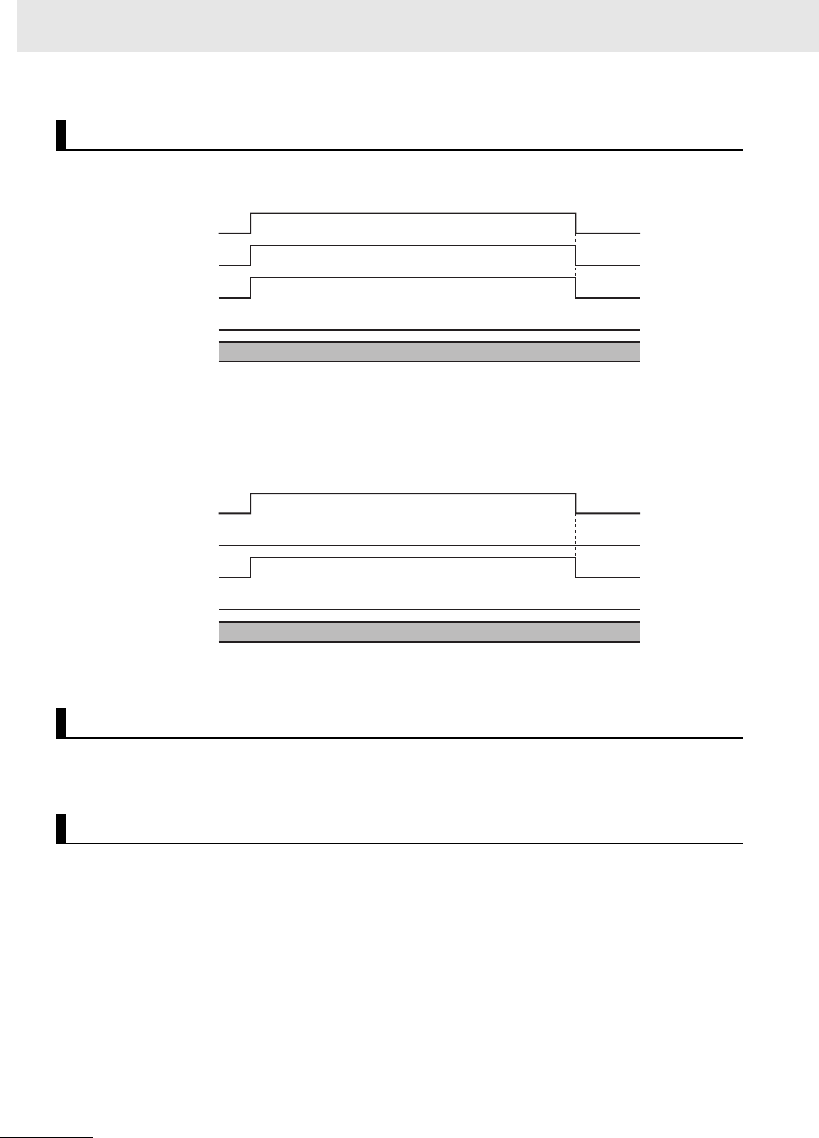
3 Axis Command Instructions
3-404
NJ/NX-series Motion Control Instructions Reference Manual (W508)
A timing chart for execution of the MC_DigitalCamSwitch (Enable Digital Cam Switch) instruction is
shown below.
The following timing chart is for when an unused axis is specified or when an MC Test Run is in prog-
ress.
For a CPU Unit with unit version 1.09 or later, the timing chart will be the same if the Count Mode is
Rotary Mode and OnCompensation (ON Time Compensation) or OffCompensation (OFF Time Com-
pensation) is set to a time that exceeds half a rotation of the axis.
Here, EnableOut in Outputs will be FALSE.
You cannot re-execute enable-type motion instructions.
Every instance of this instruction is executed independently. The restrictions for multi-execution of
motion control instructions do not apply.
For details on multi-execution of motion control instructions, refer to the NJ/NX-series CPU Unit Motion
Control User's Manual (Cat. No. W507) or NY-series Industrial Panel PC / Industrial Box PC Motion
Control User’s Manual (Cat. No. W559).
Timing Charts
Re-execution of Motion Control Instructions
Multi-execution of Motion Control Instructions
Busy
InOperation
Error
16#0000
ErrorID
Enable
Busy
InOperation
Error
16#0000
ErrorID
Enable

3-405
3 Axis Command Instructions
NJ/NX-series Motion Control Instructions Reference Manual (W508)
MC_DigitalCamSwitch
3
Function
If this instruction cannot be executed, an error occurs and Error of this instruction changes to TRUE.
You can find out the cause of the error by referring to the value output by ErrorID (Error Code).
Timing Chart When Error Occurs
Here, EnableOut in Outputs will be FALSE.
Error Codes
Refer to A-1 Error Codes for instruction errors.
Errors
Busy
Error
16#0000
ErrorID
Enable
InOperation
Error code

3 Axis Command Instructions
3-406
NJ/NX-series Motion Control Instructions Reference Manual (W508)
This section provides sample programming for the example that is given in Setting Example on page 3-
400.
The following devices are used in this sample programming.
*1 The node address is 1 and the device name is E001.
*2 The NX Unit number is 1 and the device name is N1. It is assigned to axis 1.
*3 The NX Unit number is 2 and the device name is N2. It is assigned to axis 2.
*4 The NX Unit number is 3 and the device name is N3.
The minimum settings required for this sample programming are given below.
Axis Parameters
Axis Types
Count Modes
Ring Counters
Unit of Display
Sample Programming
Configuration Devices
Device Model number
EtherCAT Coupler Unit
NX-ECC201 (Ver.1.1)
*1
Pulse Output Unit
NX-PG0122
*2
Incremental Encoder Input Unit
NX-EC0122
*3
Digital Output Unit
NX-OD2154
*4
Parameter Settings
Axis Axis type
Axis 1 Servo axis
Axis 2 Encoder axis
Axis Count Mode
Axis 1 Rotary Mode
Axis 2 Rotary Mode
Axis Modulo maximum position Modulo minimum position
Axis 1 5000 0
Axis 2 5000 0
Axis Unit of Display
Axis 1 pulse
Axis 2 pulse

3-407
3 Axis Command Instructions
NJ/NX-series Motion Control Instructions Reference Manual (W508)
MC_DigitalCamSwitch
3
Sample Programming
Main Variables
*1 You must add 0x200A:02 (Time Stamp of Synchronous Output) to the I/O entries for the EtherCAT Coupler Unit.
Sample Programming
Ladder Diagram
Name Data type Default Comment
MC_Axis000 _sAXIS_REF --- Axis Variable for axis 1.
MC_Axis001 _sAXIS_REF --- Axis Variable for axis 2.
E001_Time_Stamp_of_Synchronous_Output ULINT ---
Device variable
*1
N3_Output_Bit_00 BOOL --- Device variable
N3_Output_Bit_00_Time_Stamp ULINT --- Device variable
N3_Output_Bit_01 BOOL --- Device variable
N3_Output_Bit_01_Time_Stamp ULINT --- Device variable
Switches ARRAY[ 0..3] OF
_sCAMSWITCH_REF
--- Input parameter for Switches in-out
variable
The element numbers correspond to
the switch numbers.
Outputs ARRAY[ 0..1] OF
_sOUTPUT_REF
--- Input parameter for Outputs in-out
variable
The element numbers correspond to
the track numbers.
TrackOptions ARRAY[ 0..1] OF
_sTRACK_REF
--- Input parameter for TrackOptions in-
out variable
The element numbers correspond to
the track numbers.
EnableMask WORD 16#0003 Input parameter for EnableMask input
variable
Tracks 0 and 1 are enabled.
StartPg
Lock1
MC_Axis000.DrvStatus.Ready
PWR
Error
Axis Axis
Enable Status
Busy
MC_Power
ErrorID
Lock1
MC_Axis000 MC_Axis000
Pwr_Status
Pwr_Bsy
Pwr_Err
Pwr_ErrID
FaultHandlerMC_Axis000.MFaultLvl.Active
FaultHandlerEN
If StartPg is TRUE, check that the Servo Drive for axis 1 is ready.
If the Servo Drive for axis 1 is ready, the Servo is turned ON.
If a minor fault level error occurs for the axis composition, the error handler for the device (FaultHandler) is executed.
Program the FaultHandler according to the device.

3 Axis Command Instructions
3-408
NJ/NX-series Motion Control Instructions Reference Manual (W508)
HM
Axis Axis
Execute
Error
ErrorID
CommandAborted
MC_Home
Done
Busy
MC_Axis000 MC_Axis000
Pwr_Status
Hm_D
Hm_Bsy
Hm_Ca
Hm_Err
Hm_ErrID
If the Servo is ON for axis 1 and home is not defined, the Home instruction is executed to define home.
InitFlag
Note: The contents of the inline ST are given below.
MC_Axis000 MC_Axis000
MC_Axis000.Details.Homed Hm_D
Vel_InVel
BufferMode
VEL
Jerk
Active
Axis Axis
Execute InVelocity
Velocity Busy
Deceleration
Error
Direction
Continuous
MC_MoveVelocity
Acceleration
CommandAborted
ErrorID
Vel_Vel
Vel_Acc
Vel_Bsy
Vel_Act
Vel_Ca
Vel_Err
Vel_ErrID
Vel_Dec
Vel_Jrk
MC_Axis001 MC_Axis001
Vel.Act
InOperation
instMC_DigitalCamSwitch
EnableMask
TrackOptions
Axis Axis
Switches Switches
Outputs Outputs
Enable
Busy
ValueSource
MC_DigitalCamSwitch
TrackOptions
InOperation
Error
Outputs
TrackOptions
Outputs
TrackOptions
Switches
DCS_Busy
DCS_Error
ErrorID DCS_ErrID
Switches
EnableMask
N3_Output_Bit_00_Time_Stamp N3_Output_Bit_00_Time_Stamp
InOperation
DOut
Enable ENO
SetDOut SetDOut
SyncOutTime
TimeStamp
NX_AryDOutTimeStamp
DOut
TimeStamp
E001_Time_Stamp_of_Synchronous_Output
N3_Output_Bit_00 N3_Output_Bit_00
Outputs[0]Outputs[0]
The MC_MoveVelocity (Velocity Control) instruction is executed if home is defined for axis 1.
After the MC_MoveVelocity (Velocity Control) instruction is executed for axis 1, the MC_DigitalCamSwitch (Enable
Digital Cam Switch) instruction is executed for axis 2.
The parameters are set for the MC_MoveVelocity (Velocity Control) instruction and for the Switches variables for the
MC_DigitalCamSwitch (Enable Digital Cam Switch) instruction.
After the MC_DigitalCamSwitch (Enable Digital Cam Switch) instruction for axis 2 starts operating, the
NX_AryDOutTimeStamp (Write Digital Output Array with Specified Time Stamps) instruction is executed.
inst_NX_AryDOutTimeStamp1

3-409
3 Axis Command Instructions
NJ/NX-series Motion Control Instructions Reference Manual (W508)
MC_DigitalCamSwitch
3
Sample Programming
Contents of Inline ST
// MC_MoveVelocity parameters
Vel_Vel := LREAL#1000.0;
Vel_Acc := LREAL#0.0;
Vel_Dec := LREAL#0.0;
Vel_Jrk := LREAL#1000.0;
InitFlag := BOOL#TRUE;
// MC_DigitalCamSwitch parameters
Switches[0].TrackNumber := UINT#0;
Switches[0].FirstOnPosition := LREAL#2000.0;
Switches[0].LastOnPosition := LREAL#3000.0;
Switches[0].AxisDirection := _eMC_DIRECTION#_mcPositiveDirection;
Switches[0].CamSwitchMode := _eMC_SWITCH_MODE#_mcPositionBased;
Switches[1].TrackNumber := UINT#0;
Switches[1].FirstOnPosition := LREAL#2500.0;
Switches[1].LastOnPosition := LREAL#3000.0;
Switches[1].AxisDirection := _eMC_DIRECTION#_mcNegativeDirection;
Switches[1].CamSwitchMode := _eMC_SWITCH_MODE#_mcPositionBased;
Switches[2].TrackNumber := UINT#0;
Switches[2].FirstOnPosition := LREAL#4000.0;
Switches[2].LastOnPosition := LREAL#1000.0;
Switches[2].AxisDirection := _eMC_DIRECTION#_mcNoDirection;
Switches[2].CamSwitchMode := _eMC_SWITCH_MODE#_mcPositionBased;
Switches[3].TrackNumber := UINT#1;
Switches[3].FirstOnPosition := LREAL#3000.0;
Switches[3].Duration := T#1350ms;
Switches[3].AxisDirection := _eMC_DIRECTION#_mcNoDirection;
Switches[3].CamSwitchMode := _eMC_SWITCH_MODE#_mcTimeBased;
N3_Output_Bit_01_Time_Stamp N3_Output_Bit_01_Time_Stamp
InOperation
DOut
Enable ENO
SetDOut SetDOut
SyncOutTime
TimeStamp
NX_AryDOutTimeStamp
DOut
TimeStamp
E001_Time_Stamp_of_Synchronous_Output
N3_Output_Bit_01 N3_Output_Bit_01
Outputs[1]Outputs[1]
inst_NX_AryDOutTimeStamp2

3 Axis Command Instructions
3-410
NJ/NX-series Motion Control Instructions Reference Manual (W508)
Main Variables
*1 You must add 0x200A:02 (Time Stamp of Synchronous Output) to the I/O entries for the EtherCAT Coupler Unit.
Sample Programming
// Processing when input parameters are not set
IF InitFlag=FALSE THEN
// MC_MoveVelocity parameters
Vel_Vel := LREAL#1000.0;
Vel_Acc := LREAL#0.0;
Vel_Dec := LREAL#0.0;
Vel_Jrk := LREAL#1000.0;
// MC_DigitalCamSwitch parameters
Switches[0].TrackNumber := UINT#0;
Switches[0].FirstOnPosition := LREAL#2000.0;
Switches[0].LastOnPosition := LREAL#3000.0;
Switches[0].AxisDirection := _eMC_DIRECTION#_mcPositiveDirection;
Switches[0].CamSwitchMode := _eMC_SWITCH_MODE#_mcPositionBased;
Switches[1].TrackNumber := UINT#0;
Switches[1].FirstOnPosition := LREAL#2500.0;
Structured Text (ST)
Name Data type Default Comment
MC_Axis000 _sAXIS_REF --- Axis Variable for axis 1.
MC_Axis001 _sAXIS_REF --- Axis Variable for axis 2.
E001_Time_Stamp_of_Synchronous_Output ULINT ---
Device variable
*1
N3_Output_Bit_00 BOOL --- Device variable
N3_Output_Bit_00_Time_Stamp ULINT --- Device variable
N3_Output_Bit_01 BOOL --- Device variable
N3_Output_Bit_01_Time_Stamp ULINT --- Device variable
Pwr_En BOOL --- This variable is assigned to the
Enable input variable from the
PWR instance of the MC_Power
instruction.
Switches ARRAY[ 0..3] OF
_sCAMSWITCH_REF
--- Input parameter for Switches in-
out variable
The element numbers correspond
to the switch numbers.
Outputs ARRAY[ 0..1] OF
_sOUTPUT_REF
--- Input parameter for Outputs in-out
variable
The element numbers correspond
to the track numbers.
TrackOptions ARRAY[ 0..1] OF
_sTRACK_REF
--- Input parameter for TrackOptions
in-out variable
The element numbers correspond
to the track numbers.
EnableMask WORD 16#0003 Input parameter for EnableMask
input variable
Tracks 0 and 1 are enabled.
Hm_Ex BOOL FALSE The HM instance of MC_Home is
executed when this variable
changes to TRUE.
Vel_Ex BOOL FALSE The VEL instance of MC_MoveVe-
locity is executed when this vari-
able changes to TRUE.

3-411
3 Axis Command Instructions
NJ/NX-series Motion Control Instructions Reference Manual (W508)
MC_DigitalCamSwitch
3
Sample Programming
Switches[1].LastOnPosition := LREAL#3000.0;
Switches[1].AxisDirection := _eMC_DIRECTION#_mcNegativeDirection;
Switches[1].CamSwitchMode := _eMC_SWITCH_MODE#_mcPositionBased;
Switches[2].TrackNumber := UINT#0;
Switches[2].FirstOnPosition := LREAL#4000.0;
Switches[2].LastOnPosition := LREAL#1000.0;
Switches[2].AxisDirection := _eMC_DIRECTION#_mcNoDirection;
Switches[2].CamSwitchMode := _eMC_SWITCH_MODE#_mcPositionBased;
Switches[3].TrackNumber := UINT#1;
Switches[3].FirstOnPosition := LREAL#3000.0;
Switches[3].Duration := T#1350ms;
Switches[3].AxisDirection := _eMC_DIRECTION#_mcNoDirection;
Switches[3].CamSwitchMode := _eMC_SWITCH_MODE#_mcTimeBased;
// InitFlag is changed to TRUE after input parameters are set.
InitFlag:=TRUE;
END_IF;
// If StartPg is TRUE and the Servo Drive is ready, the Servo for axis 1 is turned ON.
// If the Servo Drive is not ready, the Servo is turned OFF.
IF (StartPg=TRUE)
AND (MC_Axis000.DrvStatus.Ready=TRUE) THEN
Pwr_En:=TRUE;
ELSE
Pwr_En:=FALSE;
END_IF;
// If a minor fault level error occurs for axis 1, the error handler for the device (FaultHandler) is exe-
cuted.
// Program the FaultHandler according to the device.
IF MC_Axis000.MFaultLvl.Active=TRUE THEN
FaultHandler();
END_IF;
// If the Servo is ON and home is not defined, the Home instruction is executed.
IF (Pwr_Status=TRUE) THEN
Hm_Ex:=TRUE;
END_IF;
// After home is defined, MC_MoveVelocity is executed.
IF MC_Axis000.Details.Homed=TRUE AND Hm_D=TRUE THEN
Vel_Ex:=TRUE;
END_IF;
//MC_Power
PWR(
Axis := MC_Axis000,
Enable := Pwr_En,
Status => Pwr_Status,
Busy => Pwr_Bsy,
Error => Pwr_Err,
ErrorID => Pwr_ErrID
);
//MC_Home
HM(
Axis := MC_Axis000,

3 Axis Command Instructions
3-412
NJ/NX-series Motion Control Instructions Reference Manual (W508)
Execute := Hm_Ex,
Done => Hm_D,
Busy => Hm_Bsy,
CommandAborted => Hm_Ca,
Error => Hm_Err,
ErrorID => Hm_ErrID
);
//MC_MoveVelocity
VEL(
Axis := MC_Axis000,
Execute := Vel_Ex,
Velocity := Vel_Vel,
Acceleration := Vel_Acc,
Deceleration := Vel_Dec,
Jerk := Vel_Jrk,
InVelocity => Vel_InVel,
Busy => Vel_Bsy,
Active => Vel_Act,
CommandAborted => Vel_Ca,
Error => Vel_Err,
ErrorID => Vel_ErrID
);
//MC_DigitalCamSwitch
instMC_DigitalCamSwitch(
Axis := MC_Axis001,
Switches := Switches,
Outputs := Outputs,
TrackOptions := TrackOptions,
Enable := Vel_Act,
EnableMask := EnableMask,
InOperation => InOperation,
Busy => DCS_Busy,
Error => DCS_Error,
ErrorID => DCS_ErrorID );
inst_NX_AryDOutTimeStamp1(
Enable := Vel_Act,
SetDOut := Outputs[0],
SyncOutTime := E001_Time_Stamp_of_Synchronous_Output,
DOut := N3_Output_Bit_00,
TimeStamp := N3_Output_Bit_00_Time_Stamp);
inst_NX_AryDOutTimeStamp2(
Enable := Vel_Act,
SetDOut := Outputs[1],
SyncOutTime := E001_Time_Stamp_of_Synchronous_Output,
DOut := N3_Output_Bit_01,
TimeStamp := N3_Output_Bit_01_Time_Stamp);

3-413
3 Axis Command Instructions
NJ/NX-series Motion Control Instructions Reference Manual (W508)
MC_TimeStampToPos
3
Variables
MC_TimeStampToPos
The MC_TimeStampToPos instruction calculates the position of the axis for the specified time stamp.
Precautions for Correct UsePrecautions for Correct Use
You can use this instruction for an axis that is assigned to an NX-series Position Interface Unit.
The applicable NX Units are as follows: NX-EC0 and NX-ECS.
Version Information
A CPU Unit with unit version 1.06 or later and Sysmac Studio version 1.07 or higher are required
to use this instruction.
Instruction Name
FB/
FUN
Graphic expression ST expression
MC_TimeStamp-
ToPo s
Time Stamp
to Axis Posi-
tion Calcula-
tion
FB MC_TimeStampToPos_instance (
Axis :=parameter,
Enable :=parameter,
TimeStamp :=parameter,
ValueSource :=parameter,
Enabled =>parameter,
Busy =>parameter,
CalcPosition =>parameter,
Error =>parameter,
ErrorID =>parameter
);
Variables
Input Variables
Name Meaning Data type Valid range Default Description
Enable Enable BOOL TRUE or FALSE FALSE The instruction is executed while Enable
is TRUE.
TimeStamp Time Stamp ULINT Non-negative
number
0 Specifies the time stamp for which to cal-
culate the position. A time stamp that is
based on the time in a Digital Input Unit,
Encoder Input Unit, or other Unit that
supports time stamp refreshing is speci-
fied.
The unit is nanoseconds.
ValueSource
(Reserved)
Input Informa-
tion
_sMC_SOURCE --- --- (Reserved)
MC_TimestampToPos_instance
Axis Axis
Enable Enabled
Timestamp Busy
Error
ErrorID
MC_TimestampToPos
ValueSource CalcPosition

3 Axis Command Instructions
3-414
NJ/NX-series Motion Control Instructions Reference Manual (W508)
*1 Refer to Unit Conversion Settings in the NJ/NX-series CPU Unit Motion Control User’s Manual (Cat. No. W507) or NY-
series Industrial Panel PC / Industrial Box PC Motion Control User’s Manual (Cat. No. W559) for information on command
units.
*2 Refer to A-1 Error Codes
Output Variable Update Timing
*1 Specify a user-defined Axis Variable that was created in the Axis Basic Settings of the Sysmac Studio (default:
MC_Axis***) or a system-defined axis variable name (_MC_AX[*], _MC1_AX[*], or _MC2_AX[*]).
*2 Specify the encoder axis that is assigned to the NX-series Encoder Input Unit.
• The MC_TimestampToPos instruction calculates the actual current position at the time stamp that is
specified by the input variable based on the actual current position and time stamp of the axis.
• For the axis, specify an NX-series Encoder Input Unit.
• If the Count Mode is set to Linear Mode in the axis parameters and an overflow or underflow occurs
in the calculated position, the calculated value will be the underflow value or the overflow value. In
this case, no error will occur.
Output Variables
Name Meaning
Data
type
Valid range Description
Enabled Enable BOOL TRUE or FALSE TRUE when the axis is being controlled.
Busy Executing BOOL TRUE or FALSE TRUE when the instruction is acknowledged.
CalcPosition Calculated
Position
LREAL Negative number,
positive number, or
0
Contains the position for the specified time stamp.
The unit is command units.
*1
Error Error BOOL TRUE or FALSE TRUE while there is an error.
ErrorID Error Code WORD
*2
Contains the error code when an error occurs. A
value of 16#0000 indicates normal execution.
Name Timing for changing to TRUE Timing for changing to FALSE
Enabled When Enable changes to TRUE. • When Enable changes to FALSE.
• When Error changes to TRUE.
Busy When Enable changes to TRUE. • When Enable changes to FALSE.
• When Error changes to TRUE.
Error When there is an error in the execution conditions
or input parameters for the instruction.
When the error is cleared.
In-Out Variables
Name Meaning Data type
Valid
range
Description
Axis Axis _sAXIS_REF ---
Specify the axis.
*1*2
Function
Position
Current position
Current time
stamp
Specified time
stamp
Time
Calculated position

3-415
3 Axis Command Instructions
NJ/NX-series Motion Control Instructions Reference Manual (W508)
MC_TimeStampToPos
3
Function
Precautions for Correct UsePrecautions for Correct Use
• This instruction requires that you use an NX-series Encoder Input Unit and that time stamping
is operating.
Time stamping is not possible in the following cases.
• An Encoder Input Unit or Servo Drive that does not support time stamping is used.
• Object 6010 hex (Time Stamp) in the NX-series Encoder Input Unit is not assigned to a
PDO.
• The distributed clock in the EtherCAT Coupler Unit is disabled.
• An error does not occur for this instruction even if the time stamp is not updated. The position
will be calculated, but the result will not be the position for the specified time stamp.
Use this instruction only after you confirm in the MC Monitor Table or Watch Tab Page of the
Sysmac Studio that the TimeStamp member of the Axis Variable is being updated.
• This instruction calculates the position for the specified time stamp based on both the current
position and current velocity of the axis. If the axis accelerates or decelerates quickly, the cal-
culation error may increase. Use this instruction when the axis is at a constant velocity.
Verify operation sufficiently to confirm safety.
• If you specify an unused axis or if the MC Test Run is in progress, Busy will change to TRUE
and Enabled and Error will change to FALSE when Enable changes to TRUE.
• Do not create two instances with the same instance name. If you do, unintentional outputs may
occur.
A timing chart for execution of the MC_TimestampToPos (Convert Time Stamp to Axis Position) instruc-
tion is shown below.
The following timing chart is for when an unused axis is specified or when an MC Test Run in progress.
Timing Charts
Busy
CalcPosition
Enabled
Error
16#0000
ErrorID
Enable
UpdatedUndefined. Undefined.
Busy
CalcPosition
Enabled
Error
16#0000
ErrorID
Enable
Undefined.

3 Axis Command Instructions
3-416
NJ/NX-series Motion Control Instructions Reference Manual (W508)
You cannot re-execute enable-type motion instructions.
This instruction is executed independently from other instructions. The restrictions for multi-execution of
motion instructions do not apply.
For details on multi-execution of motion control instructions, refer to the NJ/NX-series CPU Unit Motion
Control User's Manual (Cat. No. W507) or NY-series Industrial Panel PC / Industrial Box PC Motion
Control User’s Manual (Cat. No. W559).
If this instruction cannot be executed, an error occurs and Error of this instruction changes to TRUE.
You can find out the cause of the error by referring to the value output by ErrorID (Error Code).
Timing Chart When Error Occurs
Error Codes
Refer to A-1 Error Codes for instruction errors.
Re-execution of Motion Control Instructions
Multi-execution of Motion Control Instructions
Errors
Busy
Error
16#0000
ErrorID
Enable
Enabled
CalcPosition
Error code
Undefined.

3-417
3 Axis Command Instructions
NJ/NX-series Motion Control Instructions Reference Manual (W508)
MC_TimeStampToPos
3
Sample Programming
This section shows sample programming that measures the distances between workpieces that move
on a conveyor belt.
The following devices are used in this sample programming.
*1 The node address is 1 and the device name is E001.
*2 The NX Unit number is 1 and the device name is N1. It is assigned to axis 1.
*3 The NX Unit number is 2 and the device name is N2. It is assigned to axis 2.
*4 The NX Unit number is 3 and the device name is N3.
The minimum settings required for this sample programming are given below.
Axis Parameters
Axis Types
Count Modes
Ring Counters
Unit of Display
Sample Programming
Configuration Devices
Device Model number
EtherCAT Coupler Unit
NX-ECC201 (Ver.1.1)
*1
Pulse Output Unit
NX-PG0122
*2
Incremental Encoder Input Unit
NX-EC0122
*3
Digital Input Unit
NX-ID3344
*4
Parameter Settings
Axis Axis type
Axis 1 Servo axis
Axis 2 Encoder axis
Axis Count Mode
Axis 1 Rotary Mode
Axis 2 Rotary Mode
Axis Modulo maximum position Modulo minimum position
Axis 1 360 0
Axis 2 360 0
Axis Unit of Display
Axis 1 degree
Axis 2 degree

3 Axis Command Instructions
3-418
NJ/NX-series Motion Control Instructions Reference Manual (W508)
The sensor output turns ON when the sensor detects a workpiece. When the workpiece passes, the
sensor output turns OFF. When the sensor detects the next workpiece, the sensor output turns ON
again. The position of the encoder input is calculated based on the time stamp when the sensor output
turns ON. The difference between two positions is the distance between the workpieces.
Main Variables
Operation Example
Ladder Diagram
Name Data type Default Comment
MC_Axis000 _sAXIS_REF --- Axis Variable for axis 1.
MC_Axis001 _sAXIS_REF --- Axis Variable for axis 2.
N3_Input_Bit_00 BOOL --- Device variable
N3_Input_Bit_00_Time_Stamp ULINT --- Device variable
Position ARRAY[ 0..1] OF
LREAL
--- Stores the calculated positions.
Count ARRAY[ 0..1] OF
ULINT
--- Stores the number of rotations.
FirstPoint UINT --- A variable that is used for processing.
LastPoint UINT --- A variable that is used for processing.
Distance LREAL --- The distance between workpieces.

3-419
3 Axis Command Instructions
NJ/NX-series Motion Control Instructions Reference Manual (W508)
MC_TimeStampToPos
3
Sample Programming
Sample Programming
StartPg
Lock1
MC_Axis000.DrvStatus.Ready
PWR
Error
Axis Axis
Enable Status
Busy
MC_Power
ErrorID
Lock1
MC_Axis000 MC_Axis000
Pwr_Status
Pwr_Bsy
Pwr_Err
Pwr_ErrID
FaultHandlerMC_Axis000.MFaultLvl.Active
FaultHandlerEN
If StartPg is TRUE, check that the Servo Drive for axis 1 is ready.
If the Servo Drive for axis 1 is ready, the Servo is turned ON.
If a minor fault level error occurs for the axis composition, the error handler for the device (FaultHandler) is executed.
Program the FaultHandler according to the device.
HM
Axis Axis
Execute
Error
ErrorID
CommandAborted
MC_Home
Done
Busy
MC_Axis000 MC_Axis000
Pwr_Status
Hm_D
Hm_Bsy
Hm_Ca
Hm_Err
Hm_ErrID
If the Servo is ON for axis 1 and home is not defined, the Home instruction is executed to define home.
InitFlag
Note: The contents of inline ST 1 are given below.
The parameters are set for the MC_MoveVelocity (Velocity Control) instruction.
MC_Axis000 MC_Axis000
MC_Axis000.Details.Homed Hm_D
Vel_InVel
BufferMode
VEL
Jerk
Active
Axis Axis
Execute InVelocity
Velocity Busy
Deceleration
Error
Direction
Continuous
MC_MoveVelocity
Acceleration
CommandAborted
ErrorID
Vel_Vel
Vel_Acc
Vel_Bsy
Vel_Act
Vel_Ca
Vel_Err
Vel_ErrID
Vel_Dec
Vel_Jrk
The MC_MoveVelocity (Velocity Control) instruction is executed if home is defined for axis 1.

3 Axis Command Instructions
3-420
NJ/NX-series Motion Control Instructions Reference Manual (W508)
Note: The contents of inline ST 4 are given below.
After two workpieces are detected, the distance between the workpieces is calculated.
inst_Enabled
Note: The contents of inline ST 3 are given below.
CalcPosition (calculated position) is obtained when the sensor output turns ON. (The position is saved alternately in
Position[0] and Position[1].
MC_Axis001 MC_Axis001
Vel.Act
Finish
Note: The contents of inline ST 2 are given below.
The number of rotations of the encoder axis is counted. (If the current value is less than the previous value, it is
assumed that the modulo maximum position has been exceeded.)
N3_Input_Bit_00
inst_Enabled
instMC_TimeStampToPos
TimeStamp
Axis Axis
Enable
Busy
ValueSource
MC_TimeStampToPos
Enabled
CalcPosition
TTP_Busy
CalcPosition
Error TTP_Err
ErrorID TTP_ErrID
N3_Input_Bit_00_Time_Stamp
After the MC_MoveVelocity (Velocity Control) instruction is executed for axis 1, the MC_TimeStampToPos (Time
Stamp to Axis Position Calculation) instruction is executed for axis 2.

3-421
3 Axis Command Instructions
NJ/NX-series Motion Control Instructions Reference Manual (W508)
MC_TimeStampToPos
3
Sample Programming
Contents of Inline ST 1
// MC_MoveVelocity parameters
Vel_Vel := LREAL#1000.0;
Vel_Acc := LREAL#0.0;
Vel_Dec := LREAL#0.0;
Vel_Jrk := LREAL#1000.0;
InitFlag := BOOL#TRUE;
Contents of Inline ST 2
IF MC_Axis001.Act.Pos=LREAL#0.0 THEN
Inc(RotaryCount);
END_IF;
Contents of Inline ST 3
IF Index < USINT#2 THEN
Position[Index] := CalcPosition;
Count[Index] := RotaryCount;
Index := Index + UINT#1;
END_IF;
IF Index >= USINT#2 THEN
Finish := BOOL#TRUE;
Index := UINT#0;
END_IF;
Contents of Inline ST 4
// First comparison: Workpiece 1= Position[0] and workpiece 2 = Position[1]
// Second comparison: Workpiece 2= Position[1] and workpiece 3 = Position[0]
// Third comparison: Workpiece 3 = Position[0] and workpiece 4 = Position[1]
//…
FirstPoint := (Index+UINT#1) MOD UINT#2;
LastPoint :=Index;
DiffCount := Count[1] - Count[0];
Distance := (ABS( DiffCount) -LINT#1)* 360.0 +
(360.0 + Position[FirstPoint] - Position[LastPoint]);

3 Axis Command Instructions
3-422
NJ/NX-series Motion Control Instructions Reference Manual (W508)
Main Variables
Sample Programming
// Processing when input parameters are not set
IF InitFlag=FALSE THEN
// MC_MoveVelocity parameters
Vel_Vel := LREAL#1000.0;
Vel_Acc := LREAL#0.0;
Vel_Dec := LREAL#0.0;
Vel_Jrk := LREAL#1000.0;
// InitFlag is changed to TRUE after input parameters are set.
InitFlag:=TRUE;
END_IF;
// If StartPg is TRUE and the Servo Drive is ready, the Servo for axis 1 is turned ON.
// If the Servo Drive is not ready, the Servo is turned OFF.
IF (StartPg=TRUE)
AND (MC_Axis000.DrvStatus.Ready=TRUE) THEN
Pwr_En:=TRUE;
ELSE
Pwr_En:=FALSE;
END_IF;
// If a minor fault level error occurs for axis 1, the error handler for the device (FaultHandler) is exe-
cuted.
// Program the FaultHandler according to the device.
IF MC_Axis000.MFaultLvl.Active=TRUE THEN
FaultHandler();
END_IF;
// If the Servo is ON and home is not defined, the Home instruction is executed.
Structured Text (ST)
Name Data type Default Comment
MC_Axis000 _sAXIS_REF --- Axis Variable for axis 1.
MC_Axis001 _sAXIS_REF --- Axis Variable for axis 2.
N3_Input_Bit_00 BOOL --- Device variable
N3_Input_Bit_00_Time_Stamp ULINT --- Device variable
Hm_Ex BOOL FALSE The HM instance of MC_Home is
executed when this variable
changes to TRUE.
Vel_Ex BOOL FALSE The VEL instance of MC_MoveVe-
locity is executed when this vari-
able changes to TRUE.
PreN3InputBit00 BOOL --- The previous value of the N3_In-
put_Bit_00 device variable.
Position ARRAY[0..1] OF
LREAL
--- Stores the calculated positions.
Count ARRAY[0..1] OF ULINT --- Stores the number of rotations.
FirstPoint UINT --- A variable that is used for process-
ing.
LastPoint UINT --- A variable that is used for process-
ing.
Distance LREAL --- The distance between work-
pieces.

3-423
3 Axis Command Instructions
NJ/NX-series Motion Control Instructions Reference Manual (W508)
MC_TimeStampToPos
3
Sample Programming
IF (Pwr_Status=TRUE) THEN
Hm_Ex:=TRUE;
END_IF;
// After home is defined, MC_MoveVelocity is executed.
IF MC_Axis000.Details.Homed=TRUE AND Hm_D=TRUE THEN
Vel_Ex:=TRUE;
END_IF;
// The number of rotations of the encoder axis is counted.
// (If the current value is less than the previous value, it is assumed that the modulo maximum posi-
tion has been exceeded.)
IF MC_Axis001.Act.Pos<PreAxis001ActPos THEN
Inc(RotaryCount);
END_IF;
PreAxis001ActPos := MC_Axis001.Act.Pos;
//MC_TimeStampToPos
instMC_TimeStampToPos(
Axis := MC_Axis001,
Enable := Vel_Ex,
TimeStamp := TimeStamp,
Enabled => inst_Enabled,
Busy => TSTP_Busy,
CalcPosition => CalcPosition,
Error => TSTP_Error,
ErrorID => TSTP_ErrorID );
// CalcPosition (calculated position) is obtained when the sensor output turns ON.
// (The position is saved alternately in Position[0] and Position[1].
IF inst_Enabled THEN
IF PreN3InputBit00=FALSE AND N3_Input_Bit_00=TRUE THEN
IF Index < UINT#2 THEN
Position[Index] := CalcPosition;
Count[Index] := RotaryCount;
Index := Index + UINT#1;
END_IF;
IF Index >= UINT#2 THEN
Finish := BOOL#TRUE;
Index := UINT#0;
END_IF;
END_IF;
END_IF;
PreN3InputBit00 := N3_Input_Bit_00;
// After two workpieces are detected, the distance between the workpieces is calculated.
// First comparison: Workpiece 1= Position[0] and workpiece 2 = Position[1]
// Second comparison: Workpiece 2= Position[1] and workpiece 3 = Position[0]
// Third comparison: Workpiece 3 = Position[0] and workpiece 4 = Position[1]
//…
IF Finish THEN
FirstPoint := (Index+UINT#1) MOD UINT#2;
LastPoint :=Index;
DiffCount := Count[1] - Count[0];
Distance := (ABS( DiffCount) -LINT#1)* 360.0 +
(360.0 + Position[FirstPoint] - Position[LastPoint]);
END_IF;

3 Axis Command Instructions
3-424
NJ/NX-series Motion Control Instructions Reference Manual (W508)
//MC_Power
PWR(
Axis := MC_Axis000,
Enable := Pwr_En,
Status => Pwr_Status,
Busy => Pwr_Bsy,
Error => Pwr_Err,
ErrorID => Pwr_ErrID
);
//MC_Home
HM(
Axis := MC_Axis000,
Execute := Hm_Ex,
Done => Hm_D,
Busy => Hm_Bsy,
CommandAborted => Hm_Ca,
Error => Hm_Err,
ErrorID => Hm_ErrID
);
//MC_MoveVelocity
VEL(
Axis := MC_Axis000,
Execute := Vel_Ex,
Velocity := Vel_Vel,
Acceleration := Vel_Acc,
Deceleration := Vel_Dec,
Jerk := Vel_Jrk,
InVelocity => Vel_InVel,
Busy => Vel_Bsy,
Active => Vel_Act,
CommandAborted => Vel_Ca,
Error => Vel_Err,
ErrorID => Vel_ErrID
);

3-425
3 Axis Command Instructions
NJ/NX-series Motion Control Instructions Reference Manual (W508)
MC_PeriodicSyncVariables
3
Variables
MC_PeriodicSyncVariables
The MC_PeriodicSyncVariables instruction periodically synchronizes Axes Variables between tasks.
Precautions for Correct UsePrecautions for Correct Use
You cannot use this instruction in an NX1P2 CPU Unit and an NJ-series CPU Unit.
*Refer to A-1 Error Codes.
Output Variable Update Timing
Instruction Name FB/FUN Graphic expression ST expression
MC_Periodic
SyncVariables
Periodic Axis
Variable Syn-
chronization
between Tasks
FB
MC_PeriodicSyncVariables_instance (
Axis :=parameter,
Enable :=parameter,
ExecID :=parameter,
Enabled =>parameter,
Busy =>parameter,
Error =>parameter,
ErrorID =>parameter
);
Variables
Input Variables
Name Meaning Data type Valid range Default Description
Enable Enable BOOL TRUE or FALSE FALSE The instruction is executed when
Enable changes to TRUE.
ExecID Execution ID UINT 2 2 Gives the ID of the task with which the
value of the variable is synchronized.
2: Priority-5 periodic task
Output Variables
Name Meaning Data type Valid range Description
Enabled Enabled BOOL TRUE or FALSE TRUE while the axis is being controlled.
Busy Executing BOOL TRUE or FALSE TRUE when the instruction is acknowledged.
Error Error BOOL TRUE or FALSE TRUE while there is an error.
ErrorID Error Code WORD
*
Contains the error code when an error occurs.
A value of 16#0000 indicates normal execution.
Name Timing for changing to TRUE Timing for changing to FALSE
Enabled When Enable changes to TRUE. • After one period when Enable is FALSE.
• When Error changes to TRUE.
Busy When Enable changes to TRUE. • When Enable changes to FALSE.
• When Error changes to TRUE.
Error When there is an error in the execution conditions
or input parameters for the instruction.
When the error is cleared.
MC_PeriodicSyncVariables_instance
Axis Axis
Enable Enabled
ExecID Busy
Error
ErrorID
MC_PeriodicSyncVariables

3 Axis Command Instructions
3-426
NJ/NX-series Motion Control Instructions Reference Manual (W508)
* Specify a user-defined Axis Variable that was created in the Axis Basic Settings of the Sysmac Studio (default: MC_Axis***)
or a system-defined axis variable name (_MC_AX[*], _MC1_AX[*], or _MC2_AX[*]).
• While Enable is TRUE, an Axis Variable is periodically synchronized between the primary periodic
task and a priority-5 periodic task.
• The synchronized Axis Variable is output to the Axis Variable system-defined variable in the specified
task.
Precautions for Correct UsePrecautions for Correct Use
• This instruction supports variable synchronization only from the primary periodic task to the
priority-5 periodic task.
• Even if the value of ExecID (Execution ID) specifies the task where that axis is assigned, an
error does not occur and Busy remains TRUE.
Additional Information
If you declare an external variable in the user program for an Axis Variable of an axis that is con-
trolled in a different task, you cannot be sure of the update timing of the accessed Axis Variable,
which will depend on when execution of the user program started.
Always use the MC_PeriodicSyncVariables (Periodic Axis Variable Synchronization between
Tasks) instruction when controls are performed in different tasks for applications that have mas-
ter-slave relationships between the controlled axes, such as those for electronic cams.
In-Out Variables
Name Meaning Data type
Valid
range
Description
Axis Axis _sAXIS_REF --- Specify the axis. *
Function

3-427
3 Axis Command Instructions
NJ/NX-series Motion Control Instructions Reference Manual (W508)
MC_PeriodicSyncVariables
3
Function
This section describes the instruction in detail.
Timing of Synchronization
You can access values in the Axis Variable of an axis that is controlled in the user program for the pri-
mary periodic task from the user program for the priority-5 periodic task.
Values are never written to the Axis Variable of an axis in the primary periodic task while the program
for the priority-5 periodic task is being executed.
The user program for the priority-5 periodic task uses the execution results from the primary periodic
task from just prior to when the start of the primary periodic task and the start of the priority-5 periodic
task coincided.
The following figure shows the timing of applying the values in an Axis Variable in the primary periodic
task to the priority-5 periodic task.
This is true even if the task periods are the same.
Instruction Details
Abbreviation Description
(A) Axis Variable updated.
Regardless of where the user program execution for the priority-5 periodic task starts, the execu-
tion results from the primary periodic task from just prior to when the start of the task periods
coincided are used.
(B) The values in the Axis Variable will not be overwritten during the user program execution.
IO UPG
MC
IO UPG
MC
IO UPG
MC
IO UPG
MC
Task period (t×2)
IO UPG MC IO UPG MC IO UPG
(A)
(B)
IO UPG
MC
Servo
Execution command
Primary
periodic task
Priority-5
periodic task
Primary period (t)
IO UPG
MC
IO UPG
MC
IO UPG
MC
Task period (t)
IO UPG
MC
IO UPG
MC
Servo
Execution command
IO UPG
MC
IO UPG
MC
IO UPG
MC
IO UPG
MC
IO UPG
MC
Primary
periodic task
Priority-5
periodic task
Primary period (t)

3 Axis Command Instructions
3-428
NJ/NX-series Motion Control Instructions Reference Manual (W508)
Additional Information
If a task period is exceeded, the execution results from just prior to when the start of the task
periods coincided are not used, rather, the execution results from the period before that period
are used.
Variable Output Area
The synchronized Axis Variable is output to the Axis Variable system-defined variable in the specified
task.
For example, if the motion control axis parameters are set as shown below, the Axis Variable system-
defined variables shown in the following figure are updated.
Note The parameters that are labeled Reserved will have the default settings except for the basic settings.
If you set Axis to axis 1 and ExecID (Execution ID) to 10#2 and execute the MC_PeriodicSyncVariables
(Periodic Axis Variable Synchronization between Tasks) instruction, the area for _MC2_Ax[1] is
updated.
Abbreviation Description
(A) Axis Variable updated.
If the task period is exceeded, the values from one more period before that period are
applied.
(B) The values in the Axis Variable will not be overwritten during the user program execution.
Axis number Motion control parameters in assigned task
Axis 0 Primary periodic task
Axis 1 Primary periodic task
Axis 2 Priority-5 periodic task
Axis 3 Primary periodic task
IO UPG
MC
IO IO UPG
MC
IO UPG MC IO UPG MC
(A)
(B)
MC
IO
Task period exceeded.
Task period (t×2)
Primary
periodic task
Priority-5
periodic task
Primary period (t)
_MC1_AX[0-255]
Primary Periodic Task
[0]
[1]
Reserved
[3]
_MC2_AX[0-255]
Priority-5 Periodic Task
Reserved
Reserved
[2]
Reserved

3-429
3 Axis Command Instructions
NJ/NX-series Motion Control Instructions Reference Manual (W508)
MC_PeriodicSyncVariables
3
Function
You cannot re-execute motion instructions with enable-type inputs.
For details on multi-execution of motion control instructions, refer to the NJ/NX-series CPU Unit Motion
Control User’s Manual (Cat. No. W507).
Multi-execution of MC_PeriodicSyncVariables Instructions
If you execute a different instance of the MC_PeriodicSyncVariables (Periodic Axis Variable Synchroni-
zation between Tasks) instruction during execution of the MC_PeriodicSyncVariables (Periodic Axis
Variable Synchronization between Tasks) instruction, both instances are executed.
If an error occurs during instruction execution, Error will change to TRUE and the axis parameters are
not written. The value before the instruction was executed will be held.
You can find out the cause of the error by referring to the value output by ErrorID (Error Code).
Timing Chart When Error Occurs
Error Codes
Refer to A-1 Error Codes for instruction errors.
Re-execution of Motion Control Instructions
Multi-execution of Motion Control Instructions
Errors
_MC1_AX[0-255]
Primary Periodic Task
[0]
[1]
Reserved
[3]
_MC2_AX[0-255]
Priority-5 Periodic Task
Reserved
[2]
[1]
Reserved
Busy
Enabled
Error
ErrorID
Enable
Error code

3 Axis Command Instructions
3-430
NJ/NX-series Motion Control Instructions Reference Manual (W508)
In this sample, axis 1 is the master axis. Axis 2 is a slave axis that requires high-speed, high-precision
control. It is assigned to the primary periodic task. Axis 3 is a slave axis that does not require precision.
It is assigned to a priority-5 periodic task. The master axis (axis 1) is assigned to the primary periodic
task.
Physical Axis Configuration
Logical Axis Configuration
Programming is placed in both the primary periodic task and priority-5 periodic task to achieve the
operation for the above application.
Sample Programming
1 : 2 2 : 3
Axis 1
Axis 2 Axis 3
1 : 2
2 : 3
Axis 1:
Master axis
Axis 2:
Slave axis
Primary periodic task
Priority-5 periodic task
MC_PeriodicSyncVariables instruction
Axis 4:
Virtual axis
Axis 3:
Slave axis
Calculations
Master axis position
Master axis velocity
Target
position given
to virtual axis.

3-431
3 Axis Command Instructions
NJ/NX-series Motion Control Instructions Reference Manual (W508)
MC_PeriodicSyncVariables
3
Sample Programming
• The MC_PeriodicSyncVariables (Periodic Axis Variable Synchronization between Tasks) instruction
is executed in the primary periodic task for the master axis (Primary_MasterAxis) assigned to the pri-
mary periodic task.
• By executing the MC_PeriodicSyncVariables (Periodic Axis Variable Synchronization between Tasks)
instruction, the Axis Variable in the master axis is periodically updated in the priority-5 periodic task.
• The main variable that is used in programming is given below.
* Always assign the master axis to the primary periodic task.
Ladder Diagram
The ladder diagram programming in the primary periodic task is given below.
• By executing the MC_PeriodicSyncVariables (Periodic Axis Variable Synchronization between Tasks)
instruction, you can access the Axis Variable for the master axis (Primary_MasterAxis) that is
updated each period, in the priority-5 periodic task.
• Based on the information for the master axis, the MC_SyncMoveAbsolute (Axes Group Cyclic Syn-
chronous Absolute Positioning) instruction is executed for the virtual master axis (Secondary_Virtual-
MasterAxis) assigned to the priority-5 periodic task to follow the master axis.
• The virtual master axis (Secondary_VirtualMasterAxis) is specified as the master axis of the slave
axis (Secondary_SlaveAxis).
• By executing the MC_GearIn (Start Gear Operation) instruction or other synchronized control instruc-
tions, you can achieve synchronized control between axes assigned to different task periods.
• The main variables that are used in programming are given below.
Programming in the Primary Periodic Task
Name Data type Comment
Primary_MasterAxis _sAXIS_REF Master axis (axis 1). The Axis Variable is _MC1_AX[0].
It is assigned to the primary periodic task. *
Programming in the Priority-5 Periodic Task
Variable Data type Comment
Secondary_VirtualMasterAxis _sAXIS_REF Virtual axis. Assigned to priority-5 periodic task.
Secondary_SlaveAxis _sAXIS_REF Slave axis (axis 3). Assigned to priority-5 periodic task.
Primary_MasterAxis * _sAXIS_REF Master axis. The Axis Variable is _MC2_AX[4].
The Axis Variable is synchronized every period by exe-
cution of the MC_PeriodicSyncVariables (Periodic Axis
Variable Synchronization between Tasks) instruction.
PeriodicSyncVariablesInst
Axis Axis
Enable
ExecID
Error
ErrorID
MC_PeriodicSyncVariables
Enabled
Busy
Primary_MasterAxis
P_On P_First_Run
Primary_MasterAxis
The MC_PeriodicSyncVariables (Periodic Axis Variable Synchronization between Tasks) instruction is executed in
the primary periodic task.

3 Axis Command Instructions
3-432
NJ/NX-series Motion Control Instructions Reference Manual (W508)
* In this sample, the Primary_MasterAxis internal variable is defined with the same name as the master axis in the
primary periodic task.
Ladder Diagram
The ladder diagram programming in the priority-5 periodic task is given below.
PhaseShift LREAL Phase shift amount
VirtualMasterAxisTargetPosition LREAL Target position of the virtual master axis for each task
period
SyncExecute BOOL Synchronized control start signal for slave axis
Variable Data type Comment
SyncMoveAbs
Axis Axis
Execute
Position
Direction
BufferMode
Error
ErrorID
CommandAborted
MC_SyncMoveAbsolute
InPosition
Busy
Active
Secondary_VirtualMasterAxis
EN ENO
In1
In2
ADD
P_On P_First_RunMode
Primary_MasterAxis.Act.Pos VirtualMasterAxisTargetPosition
PhaseShift
Secondary_VirtualMasterAxis
VirtualMasterAxisTargetPosition
The current position and phase shift amount (PhaseShift) of Primary_MasterAxis are added to obtain the command
position (VirtualMasterAxisTargetPosition) for Secondary_VirtualMasterAxis.
The MC_SyncMoveAbsolute (Cyclic Synchronous Absolute Positioning) instruction is used so that
Secondary_VirtualMasterAxis always follows Primary_MasterAxis.
Secondary_VirtualMasterAxis
Secondary_SlaveAxis
SyncExecute
Jerk
BufferMode
GearIn_Instance
ReferenceType
Active
Master Master
Slave Slave
InGearExecute
Busy
RatioDenominator
ErrorAcceleration
Deceleration
MC_GearIn
RatioNumerator
CommandAborted
ErrorID
_mcLatestCommand
Secondary_VirtualMasterAxis
Secondary_SlaveAxis
A synchronized control instruction is executed for Secondary_SlaveAxis with Secondary_VirtualMasterAxis as the
virtual master axis.

3-433
3 Axis Command Instructions
NJ/NX-series Motion Control Instructions Reference Manual (W508)
MC_SyncOffsetPosition
3
Variables
MC_SyncOffsetPosition
The MC_SyncOffsetPosition instruction compensates the position of a slave axis currently in synchronized con-
trol.
Version Information
A CPU Unit with unit version 1.10 or later and Sysmac Studio version 1.12 or higher are required
to use this instruction.
*1 Refer to Unit Conversion Settings in the NJ/NX-series CPU Unit Motion Control User's Manual (Cat. No. W507) or NY-
series Industrial Panel PC / Industrial Box PC Motion Control User’s Manual (Cat. No. W559) for information on command
units.
*2 The default value for an enumeration variable is actually not the number, but the enumerator.
Instruction Name
FB/
FUN
Graphic expression ST expression
MC_SyncOffsetPosi-
tion
Cyclic Synchro-
nous Position
Offset Compen-
sation
FB
MC_SyncOffsetPosition_instance (
Axis :=parameter,
Execute :=parameter,
OffsetPosition :=parameter,
BufferMode :=parameter,
MoveMode :=parameter,
OutputtedOffsetPosition =>parameter,
Busy =>parameter,
Active =>parameter,
CommandAborted =>parameter,
Error =>parameter,
ErrorID =>parameter
);
Variables
Input Variables
Name Meaning
Data
type
Valid range Default Description
Execute Execute BOOL TRUE or FALSE FALSE The instruction is executed when Exe-
cute changes to TRUE.
OffsetPosition Position Offset LREAL Negative number,
positive number, or 0
0 Specify the position offset to add to the
command current position.
The unit is command units.
*1
BufferMode Buffer Mode
Selection
_eM-
C_BUFF
ER_-
MODE
0: _mcAborting
0
*2
Specify the behavior when executing
more than one motion instruction.
0: Aborting
MoveMode Travel Mode _eM-
C_MOV
E_MOD
E
1: _mcRelative
0
*2
Select the travel method.
1: Relative positioning
MC_SyncOffsetPosition_instance
Axis Axis
Execute
Busy
OutputtedOffsetPosition
OffsetPosition
Active
Error
ErrorID
MC_SyncOffsetPosition
BufferMode
MoveMode CommandAborted

3 Axis Command Instructions
3-434
NJ/NX-series Motion Control Instructions Reference Manual (W508)
*1 Refer to A-1 Error Codes.
Output Variable Update Timing
*1 Specify a user-defined Axis Variable that was created in the Axis Basic Settings of the Sysmac Studio (default:
MC_Axis***) or a system-defined axis variable name (_MC_AX[*], _MC1_AX[*], or _MC2_AX[*]).
*2 Specify the encoder axis that is assigned to the NX-series Encoder Input Unit.
Output Variables
Name Meaning
Data
type
Valid range Description
OutputtedOffset-
Position
Position Off-
set Output
Value
LREAL Negative number,
positive number, or
0
Contains the position offset that was added to the
command current position.
The value is updated when Active is TRUE.
Updating is stopped and the value is retained when
CommandAborted or Error is TRUE.
Busy Executing BOOL TRUE or FALSE TRUE when the instruction is acknowledged.
Active Controlling BOOL TRUE or FALSE TRUE while the axis is being controlled.
Command-
Aborted
Instruction
Aborted
BOOL TRUE or FALSE TRUE when the instruction is aborted.
Error Error BOOL TRUE or FALSE TRUE while there is an error.
ErrorID Error Code WORD
*1
Contains the error code when an error occurs.
A value of 16#0000 indicates normal execution.
Name Timing for changing to TRUE Timing for changing to FALSE
Busy When Execute changes to TRUE. • When Error changes to TRUE.
• When CommandAborted changes to TRUE.
Active When the instruction is started. • When Error changes to TRUE.
• When CommandAborted changes to TRUE.
CommandAborted • When execution of the synchronized control
instruction is stopped.
• When this instruction is aborted because
another motion control instruction was exe-
cuted with the Buffer Mode set to Aborting.
• When this instruction is canceled due to an
error in another instruction.
• When this instruction is executed while there is
an axis error.
• When you start this instruction during MC_Stop
instruction execution.
• When Execute is TRUE and changes to
FALSE.
• After one period when Execute is FALSE.
Error When there is an error in the execution conditions
or input parameters for the instruction.
When the error is cleared.
In-Out Variables
Name Meaning Data type
Valid
range
Description
Axis Axis _sAXIS_REF ---
Specify the axis.
*1, *2

3-435
3 Axis Command Instructions
NJ/NX-series Motion Control Instructions Reference Manual (W508)
MC_SyncOffsetPosition
3
Function
• The MC_SyncOffsetPosition instruction adds an offset that is calculated based on the value of the
OffsetPosition (Position Offset) input variable to the command current position and outputs the result
to the Servo Drive.
• You can change the value of the OffsetPosition (Position Offset) input variable while the Active (Con-
trolling) output variable is TRUE.
• The starting point for this instruction is used as the starting point for OffsetPosition (Position Offset)
as long as Active (Controlling) of this instruction is TRUE. Refer to Repeatedly Starting and Stopping
this Instruction on page 3-437 for details.
• Switch 1 is turned ON only once when Execute of the motion instruction is changed to TRUE.
• Switch 2 is ON while Active (Controlling) of the MC_SyncOffsetPosition instruction is TRUE.
• When switch 2 is OFF, the offset that is added to the command position is 0.
• You can execute this instruction only for a slave axis that is currently in synchronized control.
• After execution of this instruction is started, CommandAborted (Instruction Aborted) changes to
TRUE after Done, CommandAborted (Instruction Aborted), or Error of the target synchronized control
instruction changes to TRUE.
• If CommandAborted (Instruction Aborted) or Error of this instruction changes to TRUE, the offset that
was previously added to the command position is retained.
Function
MC_SyncOffsetPosition instruction
Command position
after addition of offset
Command position
before addition of offset
Offset
Motion instruction
Servo Drive
(CSP)
Position offset
Target position
First position
Switch 1
Switch 2
-
+
+
+
0
Previous position offset

3 Axis Command Instructions
3-436
NJ/NX-series Motion Control Instructions Reference Manual (W508)
• The following timing chart shows execution of this instruction while execution of the MC_GearIn (Start
Gear Operation) instruction is in progress in the primary periodic task and then CommandAborted
(Instruction Aborted) of the MC_GearIn (Start Gear Operation) instruction changes to TRUE.
CommandAborted
Active
Execute
Active
Execute
CommandAborted
Done
Execute
OffsetPosition
0 -10
-10
-10
-10
+10
+10
+20
+20
+20
10020
OutputtedOffsetPosition
0 -10 10020
0 -10 0 101000
Offset
Command position
Primary period
Solid line: After position offset is added
Dotted line: Before position offset is added
Time
MC_SyncOffsetPosition Instruction
MC_GearIn Instruction
MC_GearOut Instruction

3-437
3 Axis Command Instructions
NJ/NX-series Motion Control Instructions Reference Manual (W508)
MC_SyncOffsetPosition
3
Function
Repeatedly Starting and Stopping this Instruction
If you execute this instruction again after it is aborted, 0 is used as the starting point for the OffsetPosi-
tion (Position Offset) input variable. If you specify 0 for OffsetPosition (Position Offset) when you exe-
cute the instruction the second time, the offset that is added to the command position is 0.
If you want to use the same starting point when you re-execute a previously aborted instruction, use
OutputtedOffsetPosition (Position Offset Output Value).
As shown in this programming sample, OutputtedOffsetPosition (Position Offset Output Value) is used
to access the position offset when execution was aborted and it is subtracted from the variable for the
input parameter specified for this instruction.
CommandAborted
Active
Execute
OffsetPosition
0020
+20
+40
+60
6040
OutputtedOffsetPosition
0020 6040
020 0202000
Offset
Command position
(increased or decreased by offset)
Time
MC_SyncOffsetPosition Instruction
Execution started the second time
EN ENO
In1
In2
SUB
Execute
Busy
InputOffsetPos OffsetPosition
PreviousOffsetPos
EN ENO
In1
In2
ADD
CA
Error
OutputtedOffsetPos PreviousOffsetPos
PreviousOffsetPos
SyncOffsetPos
Axis Axis
Execute
OffsetPosition
MoveMode
BufferMode
Error
ErrorID
CommandAborted
MC_SyncOffsetPosition
OutputtedOffsetPosition
Busy
Active
MC_Axis000
Execute
Busy
MC_Axis000
OutputtedOffsetPos
CA
Error
OffsetPosition
EN ENO
OutIn
MOVE
OffsetResetFlag
0 PreviousOffsetPos

3 Axis Command Instructions
3-438
NJ/NX-series Motion Control Instructions Reference Manual (W508)
Executable Axis Status
You can execute this instruction for any axis for which Status.Synchronized (Synchronized Motion) in
the status of the axis specified for Axis is TRUE. An error will occur if the instruction is executed for an
axis in any other status.
Command Position Handling
The value after the position offset is added is managed as the command position of the axis. Therefore,
the following errors may occur depending on the value that you set for the position offset.
• Operation Settings in Axis Parameters
• Maximum Velocity
• Maximum Acceleration
• Maximum Deceleration
• Velocity Warning Value
• Acceleration Warning Value
• Deceleration Warning Value
• In-position Check Time
• Limit Settings in Axis Parameters
• Software Limits
• Following Error Over Value
• Following Error Warning Value
• Command Position Overflow
• Command Position Underflow
CommandAborted
Active
Execute
OffsetPosition
0020
+20
+40
+60
6040
PreviousOffsetPos
060
InputOffsetPosition
020 6040
OutputtedOffsetPosition
0020 6040
0020 0 20200
Offset
Command position
(increased or decreased by offset)
Time
MC_SyncOffsetPosition Instruction

3-439
3 Axis Command Instructions
NJ/NX-series Motion Control Instructions Reference Manual (W508)
MC_SyncOffsetPosition
3
Function
The following timing charts show when the position offset is applied when this instruction is executed.
When this Instruction Is Executed in the Primary Periodic Task or Priority-5
Periodic Task
The position offset that is specified for the input is output to the Servo Drive during the next task period.
The following timing chart shows an example of the operation for when this instruction is executed in the
primary periodic task. The same information applies when it is used in a priority-5 periodic task.
When this Instruction Is Executed in the Priority-16 Periodic Task
The position offset that is specified for the input is output to the Servo Drive one primary period after the
next priority-16 periodic task.
Timing Charts
Active
Execute
OffsetPosition
+10
+20
+20
+20
10 20
Command position
Primary period
Solid line: After position offset is added
Dotted line: Before position offset is added
Time
MC_SyncOffsetPosition Instruction
Active
Execute
OffsetPosition
+10
+10
+10
+10
+20
10 20
Command position
Primary period
Solid line: After position offset is added
Dotted line: Before position offset is added
Time
MC_SyncOffsetPosition Instruction
Task period

3 Axis Command Instructions
3-440
NJ/NX-series Motion Control Instructions Reference Manual (W508)
This instruction cannot be re-executed.
A Motion Control Instruction Re-execution Disabled error (error code: 543B hex) occurs if re-execution
is attempted.
Re-execution of Motion Control Instructions

3-441
3 Axis Command Instructions
NJ/NX-series Motion Control Instructions Reference Manual (W508)
MC_SyncOffsetPosition
3
Function
For details on multi-execution of motion control instructions, refer to the NJ/NX-series CPU Unit Motion
Control User’s Manual (Cat. No. W507) or NY-series Industrial Panel PC / Industrial Box PC Motion
Control User’s Manual (Cat. No. W559).
Multi-execution of Instructions for the Target Synchronized Control Instructions
If you perform multi-execution of instructions for the synchronized control instruction for which this
instruction is being executed, CommandAborted (Instruction Aborted) of this instruction changes to
TRUE. If blending is used for multi-execution of two MC_CamIn (Start Cam Operation) instructions,
CommandAborted (Instruction Aborted) of this instruction remains FALSE and processing is continued.
In this case, the value of OffsetPosition (Position Offset) is added to the initial velocity.
The following timing chart shows the operation when this instruction is executed for an MC_GearIn
(Start Gear Operation) instruction and multi-execution of instructions is performed for another instance
of MC_GearIn (Start Gear Operation) before execution of the first instance is completed.
Multi-execution of Motion Control Instructions
CommandAborted
Active
Execute
Active
Execute
CommandAborted
Done
Execute
OffsetPosition
010
Command position
After multi-execution of instructions
Solid line: When this instruction is executed
The position offset is added to the initial velocity
for multi-execution of instructions.
Dotted line: When this instruction is not executed
Time
MC_SyncOffsetPosition Instruction
MC_GearIn Instruction 1
MC_GearIn Instruction 2

3 Axis Command Instructions
3-442
NJ/NX-series Motion Control Instructions Reference Manual (W508)
Multi-execution of MC_SyncOffsetPosition Instructions
If you perform multi-execution of MC_SyncOffsetPosition instructions, CommandAborted (Instruction
Aborted) of the instance for which execution is currently in progress changes to TRUE and the next
instance is executed. The starting point for instances that are executed later is found by adding the
position offset that was output one cycle before the previous instance was aborted. There are no other
instructions for which execution is aborted when multi-execution of instructions is used for this instruc-
tion.
A timing chart for multi-execution of MC_SyncOffsetPosition instructions is shown below.
If an error occurs during instruction execution, Error will change to TRUE and the axes will stop.
You can find out the cause of the error by referring to the value output by ErrorID (Error Code).
Timing Chart When Error Occurs
Errors
Command position
Primary period
Solid line: After position offset is added
Dotted line: Before position offset is added
Time
MC_SyncOffsetPosition Instruction 2
MC_SyncOffsetPosition Instruction 1
After multi-execution of instructions
Active
Execute
+20
+20
+10
+10
+10
+10
+10
+10
+10
+10
+10
+20
+30
+30
+30
OffsetPosition
02030
CommandAborted
Active
Execute
OffsetPosition
010
Dash-dot line:
Starting point for multi-execution of instructions
Busy
CommandAborted
Error
16#0000
ErrorID
Execute
Active
Error code


3 Axis Command Instructions
3-444
NJ/NX-series Motion Control Instructions Reference Manual (W508)

4-1
NJ/NX-series Motion Control Instructions Reference Manual (W508)
4
This section describes the instructions to perform multi-axes coordinated control for the
MC Function Module.
MC_GroupEnable . . . . . . . . . . . . . . . . . . . . . . . . . . . . . . . . . . . . . . . . . . . . . . 4-2
MC_GroupDisable . . . . . . . . . . . . . . . . . . . . . . . . . . . . . . . . . . . . . . . . . . . . . 4-6
MC_MoveLinear . . . . . . . . . . . . . . . . . . . . . . . . . . . . . . . . . . . . . . . . . . . . . . 4-10
MC_MoveLinearAbsolute . . . . . . . . . . . . . . . . . . . . . . . . . . . . . . . . . . . . . . 4-36
MC_MoveLinearRelative . . . . . . . . . . . . . . . . . . . . . . . . . . . . . . . . . . . . . . . 4-39
MC_MoveCircular2D . . . . . . . . . . . . . . . . . . . . . . . . . . . . . . . . . . . . . . . . . . 4-42
MC_GroupStop . . . . . . . . . . . . . . . . . . . . . . . . . . . . . . . . . . . . . . . . . . . . . . . 4-66
MC_GroupImmediateStop . . . . . . . . . . . . . . . . . . . . . . . . . . . . . . . . . . . . . . 4-75
MC_GroupSetOverride . . . . . . . . . . . . . . . . . . . . . . . . . . . . . . . . . . . . . . . . 4-79
MC_GroupReadPosition . . . . . . . . . . . . . . . . . . . . . . . . . . . . . . . . . . . . . . . 4-83
MC_ChangeAxesInGroup . . . . . . . . . . . . . . . . . . . . . . . . . . . . . . . . . . . . . . 4-87
MC_GroupSyncMoveAbsolute . . . . . . . . . . . . . . . . . . . . . . . . . . . . . . . . . . 4-91
MC_GroupReset . . . . . . . . . . . . . . . . . . . . . . . . . . . . . . . . . . . . . . . . . . . . . . 4-97
Axes Group Instructions

4 Axes Group Instructions
4-2
NJ/NX-series Motion Control Instructions Reference Manual (W508)
MC_GroupEnable
The MC_GroupEnable instruction enables an axes group.
* Refer to A-1 Error Codes.
Instruction Name
FB/
FUN
Graphic expression ST expression
MC_GroupEnable Enable Axes
Group
FB MC_GroupEnable_instance (
AxesGroup :=parameter,
Execute :=parameter,
Done =>parameter,
Busy =>parameter,
CommandAborted
=>parameter,
Error =>parameter,
ErrorID =>parameter
);
Variables
Input Variables
Name Meaning Data type Valid range Default Description
Execute Execute BOOL TRUE or FALSE FALSE The instruction is executed when
Execute changes to TRUE.
Output Variables
Name Meaning Data type Valid range Description
Done Done BOOL TRUE or
FALSE
TRUE when the instruction is completed.
Busy Executing BOOL TRUE or
FALSE
TRUE when the instruction is acknowledged.
CommandAborted Command
Aborted
BOOL TRUE or
FALSE
TRUE when the instruction is aborted.
Error Error BOOL TRUE or
FALSE
TRUE while there is an error.
ErrorID Error Code WORD
*
Contains the error code when an error occurs. A value
of 16#0000 indicates normal execution.
MC_GroupEnable_instance
AxesGroup AxesGroup
Execute
Error
ErrorID
CommandAborted
MC_GroupEnable
Done
Busy

4-3
4 Axes Group Instructions
NJ/NX-series Motion Control Instructions Reference Manual (W508)
MC_GroupEnable
4
Function
Output Variable Update Timing
* Specify a user-defined Axes Group Variable that was created in the Axes Group Basic Settings of the Sysmac Studio
(default: MC_Group***) or a system-defined axes group variable name (_MC_GRP[*], _MC1_GRP[*], or _MC2_GRP[*]).
Before describing the function of this instruction, the different states of axes groups are explained.
• Axes groups have two states, the GroupEnable and GroupDisable states.
• To perform multi-axes coordinated control, an axes group must be in a GroupEnable state.
You can monitor the Axes Group Variables in the system-defined variables for motion control to see if
axes groups are enabled or disabled.
Here, the Axes Group Variables are described using _MC_GRP[*] as an example. The same informa-
tion applies to _MC1_GRP[*] and _MC2_GRP[*].
Note * in _MC_GRP*. is replaced by a number between 0 and 63 for NX701 CPU Units, a number between 0 and
7 for NX1P2 CPU Units, and a number between 0 and 31 for the NJ-series CPU Units and NY-series Control-
lers.
Name Timing for changing to TRUE Timing for changing to FALSE
Done When the instruction is completed. • When Execute is TRUE and changes to FALSE.
• After one period when Execute is FALSE.
Busy When Execute changes to TRUE. • When Done changes to TRUE.
• When Error changes to TRUE.
• When CommandAborted changes to TRUE.
CommandAborted When this instruction is canceled. • When Execute is TRUE and changes to FALSE.
• After one period when Execute is FALSE.
Error When there is an error in the execution con-
ditions or input parameters for the instruc-
tion.
When the error is cleared.
In-Out Variables
Name Meaning Data type Valid range Description
AxesGroup Axes Group _sGROUP_REF ---
Specify the axes group.
*
Function
State Description
GroupEnable Multi-axes coordinated control is enabled.
You can execute any multi-axes coordinated control instructions except for the
MC_ChangeAxesInGroup (Change Axes In Group) instruction.
GroupDisable Multi-axes coordinated control is disabled. You can execute only the following multi-axes
coordinated control instructions.
• MC_GroupEnable (Enable Axes Group) instruction
• MC_GroupDisable (Disable Axes Group) instruction
• MC_GroupReset (Reset Axes Group Errors) instruction
• MC_GroupSetOverride (Set Group Overrides) instruction
• MC_GroupReadPosition (Read Axes Group Position) instruction
• MC_ChangeAxesInGroup (Change Axes in Group) instruction
Name Meaning Description
_MC_GRP*.Status.Ready Axes Group
Enabled
TRUE when the axes group is stopped and preparations
to execute an axes group instruction are completed.
_MC_GRP*.Status.Disabled Axes Group Dis-
abled
TRUE when the axes group is disabled and stopped.

4 Axes Group Instructions
4-4
NJ/NX-series Motion Control Instructions Reference Manual (W508)
• The MC_GroupEnable (Enable Axes Group) instruction places the axes group specified by Axes-
Group into the GroupEnable state.
• When an axes group is in the GroupEnable state, you can execute any multi-axes coordinated control
instructions for the axes group.
• You can set only servo axes and virtual servo axes in an axes group. An error will occur if you include
other axis types.
• All axes that belong to an axes group must be in a stopped state to enable the group.
An axis is stopped if the Status.Disabled (Axis Disabled) or Status.Standstill (Standstill) in the Axis
Variable is TRUE.
• If there are axes that already belong to another axes group and the other axes group is enabled, the
MC_GroupEnable instruction is not executed and an error will occur if you attempt to execute it.
• When an axes group is enabled, the axes in the axes group change to Coordinated Motion status.
Status.Coordinated (Coordinated Motion) in the Axis Variable changes to TRUE.
• An axes group is disabled if the MC_GroupDisable (Disable Axes Group) instruction is executed, if
operation is stopped by changing to PROGRAM mode, or if a MC Test Run is started.
Precautions for Correct UsePrecautions for Correct Use
• To use an axes group, create an axes group on the Sysmac Studio and download the settings
to the CPU Unit. You cannot change the axes in an axes group from the user program.
For a CPU Unit with unit version 1.01 or later and Sysmac Studio version 1.02 or higher, you
can use the MC_ChangeAxesInGroup (Change Axes in Group) instruction to temporarily
change axes groups.
• Use the Synchronize Menu of the Sysmac Studio to download the project.
Basic Function
Timing Charts
Axes group state
Busy
Execute
CommandAborted
Done
Error
ErrorID
GroupDisable GroupEnable
16#0000

4-5
4 Axes Group Instructions
NJ/NX-series Motion Control Instructions Reference Manual (W508)
MC_GroupEnable
4
Function
If an error occurs during execution of the MC_GroupEnable instruction, Error will change to TRUE. You
can find out the cause of the error by referring to the value output by ErrorID (Error Code).
Additional Information
Errors do not occur for individual axes in an axes group even if an error occurs for the axes
group.
Error Codes
Refer to A-1 Error Codes for instruction errors.
Errors
Busy
Execute
CommandAborted
Done
Error
ErrorID
Error code

4 Axes Group Instructions
4-6
NJ/NX-series Motion Control Instructions Reference Manual (W508)
MC_GroupDisable
The MC_GroupDisable instruction disables an axes group.
* Refer to A-1 Error Codes.
Instruction Name
FB/
FUN
Graphic expression ST expression
MC_GroupDisable Disable Axes
Group
FB MC_GroupDisable_instance (
AxesGroup :=parameter,
Execute :=parameter,
Done =>parameter,
Busy =>parameter,
CommandAborted
=>parameter,
Error =>parameter,
ErrorID =>parameter
);
Variables
Input Variables
Name Meaning Data type Valid range Default Description
Execute Execute BOOL TRUE or FALSE FALSE The instruction is executed when
Execute changes to TRUE.
Output Variables
Name Meaning Data type Valid range Description
Done Done BOOL TRUE or
FALSE
TRUE when the instruction is completed.
Busy Executing BOOL TRUE or
FALSE
TRUE when the instruction is acknowledged.
CommandAborted Command
Aborted
BOOL TRUE or
FALSE
TRUE when the instruction is aborted.
Error Error BOOL TRUE or
FALSE
TRUE while there is an error.
ErrorID Error Code WORD
*
Contains the error code when an error occurs. A value
of 16#0000 indicates normal execution.
MC_GroupDisable_instance
AxesGroup AxesGroup
Execute
Error
ErrorID
CommandAborted
MC_GroupDisable
Done
Busy

4-7
4 Axes Group Instructions
NJ/NX-series Motion Control Instructions Reference Manual (W508)
MC_GroupDisable
4
Function
Output Variable Update Timing
* Specify a user-defined Axes Group Variable that was created in the Axes Group Basic Settings of the Sysmac Studio
(default: MC_Group***) or a system-defined axes group variable name (_MC_GRP[*], _MC1_GRP[*], or _MC2_GRP[*]).
• The MC_GroupDisable instruction disables an axes group. For details on the axes group states, refer
to Function on page 4-3.
• The MC_GroupDisable (Disable Axes Group) instruction places the axes group specified by Axes-
Group into the GroupDisable state. When an axes group is in the GroupDisable state, the axes group
stops acknowledging multi-axes coordinated control instructions.
• Any buffered instruction of the specified AxesGroup is cleared when the axes group state changes to
GroupDisable.
• The axes group is disabled even while operation is stopped.
When an axes group is disabled, the status of the axes in the axes group changes from TRUE for
Status.Coordinated (Coordinated Motion) to the status of each axis.
Use Status (Axis Status) in the Axis Variable to determine the status of each axis.
Name Timing for changing to TRUE Timing for changing to FALSE
Done When the axes group state is changed to
GroupDisable.
• When Execute is TRUE and changes to FALSE.
• After one period when Execute is FALSE.
Busy When Execute changes to TRUE. • When Done changes to TRUE.
• When Error changes to TRUE.
• When CommandAborted changes to TRUE.
CommandAborted Never changes to TRUE. (Reserved) • When Execute is TRUE and changes to FALSE.
• After one period when Execute is FALSE.
Error When there is an error in the execution
conditions or input parameters for the
instruction.
When the error is cleared.
In-Out Variables
Name Meaning Data type Valid range Description
AxesGroup Axes Group _sGROUP_REF ---
Specify the axes group.
*
Function
Timing Charts
Axes group state
Busy
Execute
CommandAborted
Done
Error
ErrorID
GroupEnable
16#0000
GroupDisable

4 Axes Group Instructions
4-8
NJ/NX-series Motion Control Instructions Reference Manual (W508)
If you execute the MC_GroupDisable instruction for an AxisGroup that is under multi-axes coordinated
control, CommandAborted of multi-axes coordinated control instruction will change to TRUE. Com-
mandAborted of any buffered multi-axes coordinated control instruction will also change to TRUE. If the
axes are moving, they will decelerate to a stop at the maximum deceleration rate for each axis.
Axes group state
Axes group velocity
Multi-axes Coordinated Control 1 (Example: MC_MoveLinearAbsolute)
Busy
Execute
CommandAborted
Done
Error
ErrorID
GroupEnable GroupDisable
16#0000
Active
Busy
Execute
CommandAborted
Done
Error
ErrorID
16#0000
Active
Busy
Execute
CommandAborted
Done
Error
ErrorID
16#0000
MC_GroupDisable
Multi-axes Coordinated Control 2 (Example: MC_MoveLinearAbsolute with Buffered)

4-9
4 Axes Group Instructions
NJ/NX-series Motion Control Instructions Reference Manual (W508)
MC_GroupDisable
4
Function
If an error occurs during execution of the MC_GroupDisable instruction, Error will change to TRUE. You
can find out the cause of the error by referring to the value output by ErrorID (Error Code).
Error Codes
Refer to A-1 Error Codes for instruction errors.
Errors
Error code
Busy
Execute
Done
Error
ErrorID

4 Axes Group Instructions
4-10
NJ/NX-series Motion Control Instructions Reference Manual (W508)
MC_MoveLinear
The MC_MoveLinear instruction performs linear interpolation.
Instruction Name
FB/
FUN
Graphic expression ST expression
MC_MoveLinear Linear Interpolation FB MC_MoveLinear_instance (
AxesGroup :=parameter,
Execute :=parameter,
Position :=parameter,
Velocity :=parameter,
Acceleration :=parameter,
Deceleration :=parameter,
Jerk :=parameter,
CoordSystem :=parameter,
BufferMode :=parameter,
TransitionMode
:=parameter,
MoveMode :=parameter,
Done =>parameter,
Busy =>parameter,
Active =>parameter,
CommandAborted
=>parameter,
Error =>parameter,
ErrorID =>parameter
);
Variables
Input Variables
Name Meaning Data type Valid range Default Description
Execute Execute BOOL TRUE or FALSE FALSE The instruction is executed
when Execute changes to
TRUE.
Position Target
Position
ARRAY [0..3]
OF LREAL
Negative number, positive num-
ber, or 0
0 Specify the target position
for linear interpolation. The
unit is command units.
*1
Velocity
*2
Ta rg e t
Velocity
LREAL Positive number 0 Specify the target velocity.
The unit is command
units/s.
*1
Acceleration Accelera-
tion Rate
LREAL Non-negative number 0 Specify the acceleration
rate. The unit is command
units/s
2
.
*1
Deceleration Decelera-
tion Rate
LREAL Non-negative number 0 Specify the deceleration
rate. The unit is command
units/s
2
.
*1
Jerk Jerk LREAL Non-negative number 0 Specify the jerk. The unit is
command units/s
3
.
CoordSystem Coordinate
System
_eMC_
COORD_
SYSTEM
0: _mcACS
0
*3
Specify the coordinate sys-
tem.
0: Axis coordinate system
(ACS)
BufferMode
TransitionMode
MoveMode
Acceleration
MC_MoveLinear_instance
Deceleration
AxesGroup AxesGroup
Position
Execute
Error
ErrorID
CommandAborted
Jerk
Active
CoordSystem
MC_MoveLinear
Velocity
Done
Busy

4-11
4 Axes Group Instructions
NJ/NX-series Motion Control Instructions Reference Manual (W508)
MC_MoveLinear
4
Variables
*1 Refer to Unit Conversion Settings in the NJ/NX-series CPU Unit Motion Control User's Manual (Cat. No. W507) or NY-
series Industrial Panel PC / Industrial Box PC Motion Control User’s Manual (Cat. No. W559) for information on command
units.
*2 Always set the target velocity. If the axes are moved without setting a target velocity, an error will occur.
*3 The default value for an enumeration variable is actually not the number, but the enumerator.
*Refer to A-1 Error Codes.
BufferMode Buffer Mode
Selection
_eMC_
BUFFER_
MODE
0: _mcAborting
1: _mcBuffered
2: _mcBlendingLow
3: _mcBlendingPrevious
4: _mcBlendingNext
5: _mcBlendingHigh
0
*3
Specify the behavior when
executing more than one
motion instruction.
0: Aborting
1: Buffered
2: Blending low
3: Blending previous
4: Blending next
5: Blending high
TransitionMode Transition
Mode
_eMC_
TRANSITION_
MODE
0: _mcTMNone
10: _mcTMCornerSuperimposed
0
*3
Specify the path of motion.
0: Transition disabled
10: Superimpose corners
MoveMode Travel Mode _eMC_MOVE_
MODE
0: _mcAbsolute
1: _mcRelative
0
*3
Select the travel method.
0: Absolute positioning
1: Relative positioning
Output Variables
Name Meaning Data type Valid range Description
Done Done BOOL TRUE or FALSE TRUE when the instruction is completed.
Busy Executing BOOL TRUE or FALSE TRUE when the instruction is acknowledged.
Active Controlling BOOL TRUE or FALSE TRUE when the axes group is being controlled.
CommandAborted Command
Aborted
BOOL TRUE or FALSE TRUE when the instruction is aborted.
Error Error BOOL TRUE or FALSE TRUE while there is an error.
ErrorID Error Code WORD
*
Contains the error code when an error occurs. A
value of 16#0000 indicates normal execution.
Name Meaning Data type Valid range Default Description

4 Axes Group Instructions
4-12
NJ/NX-series Motion Control Instructions Reference Manual (W508)
Output Variable Update Timing
* Specify a user-defined Axes Group Variable that was created in the Axes Group Basic Settings of the Sysmac Studio
(default: MC_Group***) or a system-defined axes group variable name (_MC_GRP[*], _MC1_GRP[*], or _MC2_GRP[*]).
• The MC_MoveLiner instruction performs linear interpolation for 2 to 4 axes.
Precautions for Correct UsePrecautions for Correct Use
• An Instruction Execution Error with Undefined Home (error code: 5466 hex) occurs if home is
undefined for any of the composition axes in the axes group.
• You cannot execute an instruction to perform linear interpolation if a limit input is ON for any of
the logical axes that belong to the axes group.
This section describes the instruction in detail.
Linear Interpolation Procedure
Use the following procedure to perform linear interpolation.
Name Timing for changing to TRUE Timing for changing to FALSE
Done When positioning is completed. • When Execute is TRUE and changes to
FALSE.
• After one period when Execute is FALSE.
Busy When Execute changes to TRUE. • When Done changes to TRUE.
• When Error changes to TRUE.
• When CommandAborted changes to TRUE.
Active When the axes move. • When Done changes to TRUE.
• When Error changes to TRUE.
• When CommandAborted changes to TRUE.
CommandAborted • When this instruction is aborted because
another motion control instruction was exe-
cuted with the Buffer Mode set to Aborting.
• When this instruction is canceled due to an
error.
• When this instruction is executed while there
is an error.
• When you start this instruction during
MC_GroupStop instruction execution.
• When Execute is TRUE and changes to
FALSE.
• After one period when Execute is FALSE.
Error When there is an error in the execution condi-
tions or input parameters for the instruction.
When the error is cleared.
In-Out Variables
Name Meaning Data type Valid range Description
AxesGroup Axes Group _sGROUP_REF ---
Specify the axes group.
*
Function
Instruction Details

4-13
4 Axes Group Instructions
NJ/NX-series Motion Control Instructions Reference Manual (W508)
MC_MoveLinear
4
Function
1
Registering Axes Groups for Interpolation
• Select the axes group to perform interpolation.
An axes group is represented by _MC_GRP[*], or by _MC1_GRP[*] and _MC2_GRP[*].
• Specify the axis composition with Composition in the Axis Group Variables. You can specify
two to four axes.
• Specify the combination of axes to perform interpolation with the Axis Selection of the Axes
Group Variables.
• Use logical axes (axis A0 to A3) for the axes, and not axis numbers.
• Specify axis numbers for the logical axes A0 to A3 in order from the lowest number with Axis
Selection.
• The Axis number is specified as follows according to the model or series.
Additional Information
For the details of the axis numbers, refer to the NJ/NX-series CPU Unit Motion Control User’s
Manual (Cat. No. W507) or NY-series Industrial Panel PC / Industrial Box PC Motion Control
User’s Manual (Cat. No. W559).
• In the Axes Group Basic Settings of the Sysmac Studio, select the axis composition to use
and assign an axis number to the logical axis. The following example shows a 3-axis axes
group that is called MC_Group000 with the following axes registered in it: MC_Axis000,
MC_Axis001, and MC_Axis002.
Precautions for Correct UsePrecautions for Correct Use
An Instruction Not Allowed for Encoder Axis Type error (543D hex) will occur and operation will
end if an encoder axis or virtual encoder axis is included in the axes group. Make sure that you
select only servo axes or virtual servo axes.
Model or series Axis number
NX701 CPU Unit Axis 0 to Axis 255
NX1P2 CPU Unit Axis 0 to Axis 11
NJ-series CPU Unit Axis 0 to Axis 63
NY-series Controller Axis 0 to Axis 63

4 Axes Group Instructions
4-14
NJ/NX-series Motion Control Instructions Reference Manual (W508)
2
Enabling the Axes Group
• Turn ON the Servo for the composition axes of the axes group, and then define home for each
of the composition axes.
• Execute the MC_GroupEnable instruction to enable the registered axes group.
Using the Linear Interpolation instruction is now enabled.
Position (Target Position)
• Set the target position in Position (Target Position) for all of the axes specified in the Axis Selection
Axes Group Variable.
• You must create a 1×4 array variable in the Sysmac Studio to assign Position (A0, A1, A2, and
A3). You can use any variable name.
Assign the target positions for the axis to the elements of that array.
Always create a 1×4 array even if there are fewer than four axes in the axes group.
An example is shown below when the Pos1 array variable is declared on the Sysmac Studio.
The following example shows assigning the target positions to Pos1 with inline ST.
In the figure, target positions (1000.0, 2000.0, 3000.0) are assigned to axes A0 to A2.
• If an axis with the Count Mode set to Rotary Mode is set as an interpolation axis and you specify
absolute position, the target value will be the same as if Direction was set to No direction specified.
For details, refer to Direction on page 3-50.
1 Pos1[0] : =LREAL#1000.0; (* A0 *)
2 Pos1[1] : =LREAL#2000.0; (* A1 *)
3 Pos1[2] : =LREAL#3000.0; (* A2 *)
EnterVariable

4-15
4 Axes Group Instructions
NJ/NX-series Motion Control Instructions Reference Manual (W508)
MC_MoveLinear
4
Function
Velocity (Target Velocity), Acceleration (Acceleration Rate), Deceleration
(Deceleration Rate), and Jerk
Set Velocity, Acceleration, Deceleration, and Jerk to specify the interpolation velocity, acceleration
rate, deceleration rate, and jerk for linear interpolation. Linear interpolation separates the interpo-
lated motion into motion on each axis. As an example, the following figure shows linear interpolation
of 2 axes from point A to point B.
For linear interpolation of four axes, the interpolation velocity and travel distance of each axis determine
the target velocities as shown below.
F: Specified interpolation feeding velocity
Fa0: Interpolation feeding velocity based on expansion of F to axis A0
Fa1: Interpolation feeding velocity based on expansion of F to axis A1
Fa2: Interpolation feeding velocity based on expansion of F to axis A2
Fa3: Interpolation feeding velocity based on expansion of F to axis A3
Ta: Interpolation acceleration time
Td: Interpolation deceleration time
L: Travel distance on the specified path
La0, La1, La2, and La3: Travel distances of axis A0, axis A1, axis A2, and axis A3.
X
Td
Ta
F
B
Y
Ta
Fa0
Fa1
Td
La0
L
La1
Axis A0 motion
Axis A1 motion
A

4 Axes Group Instructions
4-16
NJ/NX-series Motion Control Instructions Reference Manual (W508)
L, Fa0, Fa1, Fa2, and Fa3 can be expressed with the following formulas.
Velocity (Target Velocity)
• An interpolation velocity specification error will occur if Velocity (Target Velocity) is set to 0. All
axes will stop if an axis in the specified axes group is in operation.
• If any of the calculated target velocities Fa0 to Fa3 for Velocity (Target Velocity) exceed the maxi-
mum velocity, the Velocity (Target Velocity) will be automatically adjusted so that one of the axes
operates at the maximum velocity.
Jerk
The relationships between Acceleration (Acceleration Rate), Deceleration (Deceleration Rate), and
Velocity (Target Velocity) when Jerk is set to 0 and when it is set to any other value are shown below.
• Jerk Set to 0
The command value for the velocity is created with acceleration rate At and deceleration rate Dt.
Vt: Specified interpolation velocity, At: Specified acceleration rate, Dt: Specified deceleration rate.
Fa0 = F
×
L
La0
Fa1 = F
L
La1
Fa2 = F
L
La2
Fa3 = F
L
La3
L = La0
2
+ La1
2
+ La2
2
+ La3
2
×
×
×
At
Time
Time
Deceleration rate
Acceleration rate
Interpolation velocity
Vt
-Dt

4-17
4 Axes Group Instructions
NJ/NX-series Motion Control Instructions Reference Manual (W508)
MC_MoveLinear
4
Function
• Short Travel Distance When Jerk Is 0
The interpolation velocity will not reach the specified Vt (Target Velocity).
Vt: Specified interpolation velocity, At: Specified acceleration rate, Dt: Specified deceleration rate.
• Jerk Set to Value Other Than 0
The command value for the velocity is created with At as the upper acceleration limit and Dt as the
upper deceleration limit.
Vt: Specified interpolation velocity, At: Specified acceleration rate, Dt: Specified deceleration rate,
Jt: Specified jerk
Time
Time
Acceleration rate
Interpolation velocity
Deceleration rate
Vt
At
-Dt
At
-Dt
Jt
-Jt
Vt
Time
Time
Time
Jerk
Deceleration rate
Acceleration rate
Interpolation velocity

4 Axes Group Instructions
4-18
NJ/NX-series Motion Control Instructions Reference Manual (W508)
• Short Travel Distance When Jerk Is Not 0
The interpolation velocity will not reach the specified Vt (Target Velocity).
Vt: Specified interpolation velocity, At: Specified acceleration rate, Dt: Specified deceleration rate,
Jt: Specified jerk
Additional Information
• If 0 is specified for Acceleration (Acceleration Rate), the specified Velocity (Target Velocity) is
used immediately.
• If 0 is specified for Deceleration (Deceleration Rate), the axis stops immediately. However, if
the Buffer Mode is set to a blending mode, axis operation will change to the target velocity
specified by the next operation without stopping. For details, refer to BufferMode (Buffer Mode
Selection) on page 4-19.
• When the Acceleration (Acceleration Rate) or Deceleration (Deceleration Rate) is 0, the jerk
setting is disabled.
CoordSystem (Coordinate System)
CoordSystem specifies the coordinate system to use for linear interpolation. Only an axis coordinate
system (ACS) consisting of two or more axes is supported.
At
-Dt
Jt
-Jt
Vt
Time
Time
Time
Jerk
Acceleration rate
Interpolation velocity
Deceleration rate

4-19
4 Axes Group Instructions
NJ/NX-series Motion Control Instructions Reference Manual (W508)
MC_MoveLinear
4
Function
BufferMode (Buffer Mode Selection)
• BufferMode specifies how to join the axis motions for this interpolation instruction and the previous
interpolation instruction.
• There are the following six settings.
For details on BufferMode (Buffer Mode Selection), refer to the NJ/NX-series CPU Unit Motion Con-
trol User's Manual (Cat. No. W507) or NY-series Industrial Panel PC / Industrial Box PC Motion Con-
trol User’s Manual (Cat. No. W559).
TransitionMode
• TransitionMode specifies how to combine the paths created by the previous interpolation opera-
tion and the next interpolation operation.
• Set the TransitionMode to either _mcTMNone (Transition Disabled) or _mcTMCornerSuperim-
posed (Superimpose Corners).
• TransitionMode is enabled when blending is specified for BufferMode.
• An error will occur if you do not set TransitionMode to _mcTMNone (Transition Disabled) when
blending is not used.
Buffer Mode Selection Description
Aborting Aborts the instruction being executed and switches to this instruction.
If the direction of axis motion is reversed by switching instructions, the motion
will be reversed according to the Operation Selection at Reversing axis
parameter.
Buffered Buffers this instruction and executes it automatically after the current instruc-
tion is completed.
Blending Starts the buffered instruction at the velocity (transit velocity) at which the cur-
rent instruction reaches the target position. The operation of the current
instruction is changed so that the axes reach the target position at the transit
velocity. There are four methods to specify the transit velocity. These are
described below. You can also specify a Transition Mode as an option to the
Blending Mode (see below).
Blending low The lower of the target velocities of the current instruction and the buffered
instruction is used as the transit velocity.
Blending previous The target velocity of the current instruction is used as the transit velocity.
Blending next The target velocity of the buffered instruction is used as the transit velocity.
Blending high The higher of the target velocities of the current instruction and the buffered
instruction is used as the transit velocity.

4 Axes Group Instructions
4-20
NJ/NX-series Motion Control Instructions Reference Manual (W508)
Transition Disabled
The path is given priority when creating the velocity command value, so velocity command values of
the axes may change rapidly when switching from one operation to the next.
Operation Example
The Velocity (Target Velocity), BufferMode, and TransitionMode when transitioning from P1 to P2,
and from P2 to P3 are shown below.
• Motion from P1 to P2: Velocity = F, BufferMode = Aborting, TransitionMode = _mcTMNone (Tran-
sition Disabled)
• Motion from P2 to P3: Velocity = F, BufferMode = Blend with next, TransitionMode = _mcTMNone
(Transition Disabled)
• The motion starts from position P1 and goes through position P2. Linear interpolation is per-
formed to position P3.
• The linear interpolation velocity F is maintained when passing position P2. Because of this, the
velocity is discontinuous at position P2 as shown in the following figure.
Velocity of axis A0
Velocity of axis A1
Interpolation
velocity F
A1
A0
P3
P2P1
The velocity is
discontinuous.
The velocity is
discontinuous.

4-21
4 Axes Group Instructions
NJ/NX-series Motion Control Instructions Reference Manual (W508)
MC_MoveLinear
4
Function
Superimpose Corners
Use the superimpose corners specification when you want make the axes command velocities con-
tinuous.
Operation Example
The Velocity (Target Velocity), BufferMode, and TransitionMode when transitioning from P1 to P2,
and from P2 to P3 are shown below.
• Motion from P1 to P2: Velocity = F, BufferMode = Aborting, TransitionMode = _mcTMNone (Tran-
sition Disabled)
• Motion from P2 to P3: Velocity = F, BufferMode = Blend with next, TransitionMode = _mcTM-
CornerSuperimposed (Superimpose Corners)
• The motion starts from position P1 and passes near position P2. Linear interpolation is performed
to position P3.
• To make the axes command velocities continuous, the deceleration range of the previous motion
and the acceleration range of the current motion are combined to create the command velocity.
For this reason, the acceleration time of the current motion is the same as the deceleration time of
the previous motion.
The combined path passes near P2.
The distance from P2 to the path is longer when the interpolation velocity is faster or the decelera-
tion rate of the previous instruction is smaller. It is shorter when the interpolation velocity is slower or
the deceleration rate of the previous instruction is larger.
Additional Information
The Jerk settings are disabled in the region with superimposed corners.
A1
A0
P3
P2
P1
The velocity command is
made continuous by
combining the deceleration
range of the previous
motion and the acceleration
range of the current motion.
Velocity of axis A0
Velocity of axis A1
The path goes
near P2.
The velocity is
continuous.

4 Axes Group Instructions
4-22
NJ/NX-series Motion Control Instructions Reference Manual (W508)
This instruction cannot be re-executed. A Motion Control Instruction Re-execution Disabled error (error
code: 543B hex) occurs if re-execution is attempted, and all axes in the linear interpolation motion stop.
A restriction applies to the instructions that can be used while this instruction is in execution.
For details on multi-execution of motion control instructions, refer to the NJ/NX-series CPU Unit Motion
Control User’s Manual (Cat. No. W507) or NY-series Industrial Panel PC / Industrial Box PC Motion
Control User’s Manual (Cat. No. W559).
If an error occurs during instruction execution, Error will change to TRUE and the axes will stop. You
can find out the cause of the error by referring to the value output by ErrorID (Error Code).
Error Codes
Refer to A-1 Error Codes for instruction errors.
Re-execution of Motion Control Instructions
Multi-execution of Motion Control Instructions
Errors
Time
Error code
Interpolation velocity
Busy
Execute
CommandAborted
Done
Error
ErrorID
Active
16#0000
Error code
Busy
Execute
CommandAborted
Done
Error
ErrorID
Active
16#0000

4-23
4 Axes Group Instructions
NJ/NX-series Motion Control Instructions Reference Manual (W508)
MC_MoveLinear
4
Sample Programming
This section shows sample programming for linear interpolation with periodic multi-execution of instruc-
tions.
The minimum settings required for this sample programming are given below.
Setting Axis Parameters
Axis Types
Count Modes
Units of Display
Axes Group Parameter Settings
Axis Composition
Two axes are set.
Axis Selection
Axis 1 and axis 2 are set.
Sample Programming
Parameter Settings
Axis Axis Type
Axis 1 Servo axis
Axis 2 Servo axis
Axis Count Mode
Axis 1 Linear Mode
Axis 2 Linear Mode
Axis Unit of Display
Axis 1 mm
Axis 2 mm

4 Axes Group Instructions
4-24
NJ/NX-series Motion Control Instructions Reference Manual (W508)
The following is an example of operation that performs linear interpolation automatically and
then returns to home and stops. Linear interpolations (2) to (7) are executed with multi-exe-
cution of instructions while linear interpolation (1) is being executed. Set the Buffer Mode
Selection to Buffered. In this sample, multi-execution of instructions is performed for (2) to
(7) if the Active (Controlling) output variable from linear interpolation (1) is TRUE. For multi-
axes coordinated operation, multi-execution is possible for up to seven instructions.
Operation Pattern
Positioning is performed using linear interpolations in the order (Axis1, Axis2) = (50.00 mm, 5.00
mm) → (0.00 mm, 10.00 mm) → (50.00 mm, 15.00 mm) → (0.00 mm, 20.00 mm) → (50.00 mm,
25.00 mm) → (50.00 mm, 0.00 mm) → (0.00 mm, 0.00 mm), then stop.
Main Variables
Operation Example
Ladder Diagram
Name Data type Default Comment
MC_Group000 _sGROUP
_REF
--- This is the Axes Group Variable for axes group
0.
MC_Group000.MFaultLvl.Active BOOL FALSE TRUE while there is a minor fault level error for
axes group 0.
MC_Group000.Status.Disabled BOOL FALSE The value is TRUE when axes group 0 is dis-
abled.
MC_Axis000 _sAXIS_REF --- This is the Axis Variable for axis 1.
MC_Axis000.Details.Homed BOOL FALSE TRUE when home is defined for axis 1.
MC_Axis000.MFaultLvl.Active BOOL FALSE TRUE while there is a minor fault level error for
axis 1.
MC_Axis001 _sAXIS_REF --- This is the Axis Variable for axis 2.
MC_Axis001.Details.Homed BOOL FALSE TRUE when home is defined for axis 2.
MC_Axis001.MFaultLvl.Active BOOL FALSE TRUE while there is a minor fault level error for
axis 2.
Pwr1_Status BOOL FALSE This variable is assigned to the Status output
variable from the PWR1 instance of the
MC_Power instruction. This variable changes to
TRUE when the Servo is turned ON.
15.00
20.00
25.00
(1)
(2)
(3)
(4)
(5)
(6)
(7)
5.00
10.00
0.00 50.00
Positive direction
Axis 2 (mm)
Positive direction
Axis 1 (mm)

4-25
4 Axes Group Instructions
NJ/NX-series Motion Control Instructions Reference Manual (W508)
MC_MoveLinear
4
Sample Programming
Sample Programming
Pwr2_Status BOOL FALSE This variable is assigned to the Status output
variable from the PWR2 instance of the
MC_Power instruction. This variable changes to
TRUE when the Servo is turned ON.
StartPg BOOL FALSE The Servos for the axes in the axes group are
turned ON if this variable is TRUE and Ether-
CAT process data communications are estab-
lished.
InitFlag BOOL FALSE This variable indicates if it is necessary to set
the input parameters. Input parameters are set
when this variable is FALSE. When setting the
input parameters is completed, this variable
changes to TRUE.
Name Data type Default Comment
StartPg
Lock1
MC_Axis000.DrvStatus.Ready
PWR1
Error
Axis Axis
Enable Status
Busy
MC_Power
ErrorID
Lock1
MC_Axis000
Pwr1_Status
Pwr1_Bsy
Pwr1_Err
Pwr1_ErrID
FaultHandlerMC_Axis000.MFaultLvl.Active
FaultHandlerEN
MC_Axis001.MFaultLvl.Active
MC_Group000.MFaultLvl.Active
Lock2
MC_Axis001.DrvStatus.Ready
PWR2
Error
Axis Axis
Enable Status
Busy
MC_Power
ErrorID
Lock2
MC_Axis001
Pwr2_Status
Pwr2_Bsy
Pwr2_Err
Pwr2_ErrID
If StartPg is TRUE, check that the Servo Drives for each axis are ready.
If the Servo Drives are ready, the Servos are turned ON for each axis.
If a minor fault level error occurs for the axis composition, the error handler for the device (FaultHandler) is executed.
Program the FaultHandler according to the device.

4 Axes Group Instructions
4-26
NJ/NX-series Motion Control Instructions Reference Manual (W508)
HM2
Axis Axis
Execute
Error
ErrorID
CommandAborted
MC_Home
Done
Busy
MC_Axis001
Pwr2_Status
Hm2_D
Hm2_Bsy
Hm2_Ca
Hm2_Err
Hm2_ErrID
GRP_EN
AxesGroup AxesGroup
Execute
Error
ErrorID
CommandAborted
MC_GroupEnable
Done
Busy
Hm1_D Hm2_D MC_Group000.Status.Disabled
MC_Group000
Grp_En_D
Grp_En_Bsy
Grp_En_Ca
Grp_En_Err
Grp_En_ErrID
InitFlag
MC_Axis001.Details.Homed
BufferMode
TransitionMode
MoveMode
Acceleration
MV_LIN1
Deceleration
A
xesGroup
A
xesGroup
P
osition
Execute
Error
ErrorID
CommandAborted
Jerk
Active
CoordSystem
MC_MoveLinear
Velocity
Done
Busy
MC_Group000
Grp_En_D
Mv_Lin1_Bsy
Mv_Lin1_Ca
Mv_Lin1_Err
Mv_Lin1_ErrID
Mv_Lin1_Act
Mv_Lin1_Pos
Mv_Lin1_Vel
Mv_Lin1_Acc
Mv_Lin1_Dec
Mv_Lin1_Mm
Mv_Lin1_D
HM1
Axis Axis
Execute
Error
ErrorID
CommandAborted
MC_Home
Done
Busy
MC_Axis000
Pwr1_Status
Hm1_D
Hm1_Bsy
Hm1_Ca
Hm1_Err
Hm1_ErrID
MC_Axis000.Details.Homed
If the Servo is ON for axis 2 and home is not defined, the Home instruction is executed to define home.
After home is defined for axis 1 and axis 2, the axes group is enabled.
The parameters are set for linear interpolation.
If the axes group is enabled, linear interpolation (1) is executed.
If the Servo is ON for axis 1 and home is not defined, the Home instruction is executed to define home.
Note: The contents of the inline
ST are given below.

4-27
4 Axes Group Instructions
NJ/NX-series Motion Control Instructions Reference Manual (W508)
MC_MoveLinear
4
Sample Programming
BufferMode
TransitionMode
MoveMode
Acceleration
MV_LIN3
Deceleration
A
xesGroup
A
xesGroup
P
osition
Execute
Error
ErrorID
CommandAborted
Jerk
Active
CoordSystem
MC_MoveLinear
Velocity
Done
Busy
MC_Group000
Mv_Lin1_Act
Mv_Lin3_Bsy
Mv_Lin3_Ca
Mv_Lin3_Err
Mv_Lin3_ErrID
Mv_Lin3_Act
Mv_Lin3_Pos
Mv_Lin3_Vel
Mv_Lin3_Acc
Mv_Lin3_Dec
Mv_Lin3_Bm
Mv_Lin3_Mm
Mv_Lin3_D
BufferMode
TransitionMode
MoveMode
Acceleration
MV_LIN4
Deceleration
A
xesGroup
A
xesGroup
P
osition
Execute
Error
ErrorID
CommandAborted
Jerk
Active
CoordSystem
MC_MoveLinear
Velocity
Done
Busy
MC_Group000
Mv_Lin1_Act
Mv_Lin4_Bsy
Mv_Lin4_Ca
Mv_Lin4_Err
Mv_Lin4_ErrID
Mv_Lin4_Act
Mv_Lin4_Pos
Mv_Lin4_Vel
Mv_Lin4_Acc
Mv_Lin4_Dec
Mv_Lin4_Bm
Mv_Lin4_Mm
Mv_Lin4_D
BufferMode
TransitionMode
MoveMode
Acceleration
MV_LIN2
Deceleration
A
xesGroup
A
xesGroup
P
osition
Execute
Error
ErrorID
CommandAborted
Jerk
Active
CoordSystem
MC_MoveLinear
Velocity
Done
Busy
MC_Group000
Mv_Lin1_Act
Mv_Lin2_Bsy
Mv_Lin2_Ca
Mv_Lin2_Err
Mv_Lin2_ErrID
Mv_Lin2_Act
Mv_Lin2_Pos
Mv_Lin2_Vel
Mv_Lin2_Acc
Mv_Lin2_Dec
Mv_Lin2_Bm
Mv_Lin2_Mm
Mv_Lin2_D
Linear interpolation (3) is executed with multi-execution of instructions after linear interpolation (1) is started.
Linear interpolation (4) is executed with multi-execution of instructions after linear interpolation (1) is started.
Linear interpolation (2) is executed with multi-execution of instructions after linear interpolation (1) is started.

4 Axes Group Instructions
4-28
NJ/NX-series Motion Control Instructions Reference Manual (W508)
Contents of Inline ST
// MV_LIN1 parameters
Mv_Lin1_Pos[0] := LREAL#50.0;
Mv_Lin1_Pos[1] := LREAL#5.0;
Mv_Lin1_Vel := LREAL#100.0;
Mv_Lin1_Acc := LREAL#100.0;
Mv_Lin1_Dec := LREAL#100.0;
Mv_Lin1_Mm := _eMC_MOVE_MODE#_mcAbsolute;
// MV_LIN2 parameters
Mv_Lin2_Pos[0] := LREAL#0.0;
Mv_Lin2_Pos[1] := LREAL#10.0;
Mv_Lin2_Vel := LREAL#100.0;
Mv_Lin2_Acc := LREAL#100.0;
MC_Group000
Mv_Lin1_Act
Mv_Lin6_Bsy
Mv_Lin6_Ca
Mv_Lin6_Err
Mv_Lin6_ErrID
Mv_Lin6_Act
Mv_Lin6_Pos
Mv_Lin6_Vel
Mv_Lin6_Acc
Mv_Lin6_Dec
Mv_Lin6_Bm
Mv_Lin6_D
BufferMode
TransitionMode
MoveMode
Acceleration
MV_LIN6
Deceleration
A
xesGroup
A
xesGroup
P
osition
Execute
Error
ErrorID
CommandAborted
Jerk
Active
CoordSystem
MC_MoveLinear
Velocity
Done
Busy
Mv_Lin6_Mm
BufferMode
TransitionMode
MoveMode
Acceleration
MV_LIN7
Deceleration
A
xesGroup
A
xesGroup
P
osition
Execute
Error
ErrorID
CommandAborted
Jerk
Active
CoordSystem
MC_MoveLinear
Velocity
Done
Busy
MC_Group000
Mv_Lin1_Act
Mv_Lin7_Bsy
Mv_Lin7_Ca
Mv_Lin7_Err
Mv_Lin7_ErrID
Mv_Lin7_Act
Mv_Lin7_Pos
Mv_Lin7_Vel
Mv_Lin7_Acc
Mv_Lin7_Dec
Mv_Lin7_Bm
Mv_Lin7_Mm
Mv_Lin7_D
MC_Group000
Mv_Lin1_Act
Mv_Lin5_Bsy
Mv_Lin5_Ca
Mv_Lin5_Err
Mv_Lin5_ErrID
Mv_Lin5_Act
Mv_Lin5_Pos
Mv_Lin5_Vel
Mv_Lin5_Acc
Mv_Lin5_Dec
Mv_Lin5_Bm
Mv_Lin5_D
BufferMode
TransitionMode
MoveMode
Acceleration
MV_LIN5
Deceleration
A
xesGroup
A
xesGroup
P
osition
Execute
Error
ErrorID
CommandAborted
Jerk
Active
CoordSystem
MC_MoveLinear
Velocity
Done
Busy
Mv_Lin5_Mm
Linear interpolation (6) is executed with multi-execution of instructions after linear interpolation (1) is started.
Linear interpolation (7) is executed with multi-execution of instructions after linear interpolation (1) is started.
Linear interpolation (5) is executed with multi-execution of instructions after linear interpolation (1) is started.

4-29
4 Axes Group Instructions
NJ/NX-series Motion Control Instructions Reference Manual (W508)
MC_MoveLinear
4
Sample Programming
Mv_Lin2_Dec := LREAL#100.0;
Mv_Lin2_Bm := _eMC_BUFFER_MODE#_mcBuffered;
Mv_Lin2_Mm := _eMC_MOVE_MODE#_mcAbsolute;
// MV_LIN3 parameters
Mv_Lin3_Pos[0] := LREAL#50.0;
Mv_Lin3_Pos[1] := LREAL#15.0;
Mv_Lin3_Vel := LREAL#100.0;
Mv_Lin3_Acc := LREAL#100.0;
Mv_Lin3_Dec := LREAL#100.0;
Mv_Lin3_Bm := _eMC_BUFFER_MODE#_mcBuffered;
Mv_Lin3_Mm := _eMC_MOVE_MODE#_mcAbsolute;
// MV_LIN4 parameters
Mv_Lin4_Pos[0] := LREAL#0.0;
Mv_Lin4_Pos[1] := LREAL#20.0;
Mv_Lin4_Vel := LREAL#100.0;
Mv_Lin4_Acc := LREAL#100.0;
Mv_Lin4_Dec := LREAL#100.0;
Mv_Lin4_Bm := _eMC_BUFFER_MODE#_mcBuffered;
Mv_Lin4_Mm := _eMC_MOVE_MODE#_mcAbsolute;
// MV_LIN5 parameters
Mv_Lin5_Pos[0] := LREAL#50.0;
Mv_Lin5_Pos[1] := LREAL#25.0;
Mv_Lin5_Vel := LREAL#100.0;
Mv_Lin5_Acc := LREAL#100.0;
Mv_Lin5_Dec := LREAL#100.0;
Mv_Lin5_Bm := _eMC_BUFFER_MODE#_mcBuffered;
Mv_Lin5_Mm := _eMC_MOVE_MODE#_mcAbsolute;
// MV_LIN6 parameters
Mv_Lin6_Pos[0] := LREAL#50.0;
Mv_Lin6_Pos[1] := LREAL#0.0;
Mv_Lin6_Vel := LREAL#100.0;
Mv_Lin6_Acc := LREAL#100.0;
Mv_Lin6_Dec := LREAL#100.0;
Mv_Lin6_Bm := _eMC_BUFFER_MODE#_mcBuffered;
Mv_Lin6_Mm := _eMC_MOVE_MODE#_mcAbsolute;
// MV_LIN7 parameters
Mv_Lin7_Pos[0] := LREAL#0.0;
Mv_Lin7_Pos[1] := LREAL#0.0;
Mv_Lin7_Vel := LREAL#100.0;
Mv_Lin7_Acc := LREAL#100.0;
Mv_Lin7_Dec := LREAL#100.0;
Mv_Lin7_Bm := _eMC_BUFFER_MODE#_mcBuffered;
Mv_Lin7_Mm := _eMC_MOVE_MODE#_mcAbsolute;
// InitFlag is changed to TRUE after input parameters are set.
InitFlag := TRUE;

4 Axes Group Instructions
4-30
NJ/NX-series Motion Control Instructions Reference Manual (W508)
Main Variables
Sample Programming
// Processing when input parameters are not set
IF InitFlag=FALSE THEN
// MV_LIN1 parameters
Mv_Lin1_Pos[0] := LREAL#50.0;
Mv_Lin1_Pos[1] := LREAL#5.0;
Mv_Lin1_Vel := LREAL#100.0;
Mv_Lin1_Acc := LREAL#100.0;
Mv_Lin1_Dec := LREAL#100.0;
Mv_Lin1_Mm := _eMC_MOVE_MODE#_mcAbsolute;
Structured Text (ST)
Name Data type Default Comment
MC_Group000 _sGROUP
_REF
--- This is the Axes Group Variable for axes group
0.
MC_Group000.MFaultLvl.Active BOOL FALSE TRUE while there is a minor fault level error for
axes group 0.
MC_Group000.Status.Disabled BOOL FALSE The value is TRUE when axes group 0 is dis-
abled.
MC_Axis000 _sAXIS_REF --- This is the Axis Variable for axis 1.
MC_Axis000.Details.Homed BOOL FALSE TRUE when home is defined for axis 1.
MC_Axis000.MFaultLvl.Active BOOL FALSE TRUE while there is a minor fault level error for
axis 1.
MC_Axis001 _sAXIS_REF --- This is the Axis Variable for axis 2.
MC_Axis001.Details.Homed BOOL FALSE TRUE when home is defined for axis 2.
MC_Axis001.MFaultLvl.Active BOOL FALSE TRUE while there is a minor fault level error for
axis 2.
Pwr1_Status BOOL FALSE This variable is assigned to the Status output
variable from the PWR1 instance of the
MC_Power instruction. This variable changes to
TRUE when the Servo is turned ON.
Pwr2_Status BOOL FALSE This variable is assigned to the Status output
variable from the PWR2 instance of the
MC_Power instruction. This variable changes to
TRUE when the Servo is turned ON.
StartPg BOOL FALSE The Servos for the axes in the axes group are
turned ON if this variable is TRUE and Ether-
CAT process data communications are estab-
lished.
InitFlag BOOL FALSE This variable indicates if it is necessary to set
the input parameters. Input parameters are set
when this variable is FALSE. When setting the
input parameters is completed, this variable
changes to TRUE.

4-31
4 Axes Group Instructions
NJ/NX-series Motion Control Instructions Reference Manual (W508)
MC_MoveLinear
4
Sample Programming
// MV_LIN2 parameters
Mv_Lin2_Pos[0] := LREAL#0.0;
Mv_Lin2_Pos[1] := LREAL#10.0;
Mv_Lin2_Vel := LREAL#100.0;
Mv_Lin2_Acc := LREAL#100.0;
Mv_Lin2_Dec := LREAL#100.0;
Mv_Lin2_Bm := _eMC_BUFFER_MODE#_mcBuffered;
Mv_Lin2_Mm := _eMC_MOVE_MODE#_mcAbsolute;
// MV_LIN3 parameters
Mv_Lin3_Pos[0] := LREAL#50.0;
Mv_Lin3_Pos[1] := LREAL#15.0;
Mv_Lin3_Vel := LREAL#100.0;
Mv_Lin3_Acc := LREAL#100.0;
Mv_Lin3_Dec := LREAL#100.0;
Mv_Lin3_Bm := _eMC_BUFFER_MODE#_mcBuffered;
Mv_Lin3_Mm := _eMC_MOVE_MODE#_mcAbsolute;
// MV_LIN4 parameters
Mv_Lin4_Pos[0] := LREAL#0.0;
Mv_Lin4_Pos[1] := LREAL#20.0;
Mv_Lin4_Vel := LREAL#100.0;
Mv_Lin4_Acc := LREAL#100.0;
Mv_Lin4_Dec := LREAL#100.0;
Mv_Lin4_Bm := _eMC_BUFFER_MODE#_mcBuffered;
Mv_Lin4_Mm := _eMC_MOVE_MODE#_mcAbsolute;
// MV_LIN5 parameters
Mv_Lin5_Pos[0] := LREAL#50.0;
Mv_Lin5_Pos[1] := LREAL#25.0;
Mv_Lin5_Vel := LREAL#100.0;
Mv_Lin5_Acc := LREAL#100.0;
Mv_Lin5_Dec := LREAL#100.0;
Mv_Lin5_Bm := _eMC_BUFFER_MODE#_mcBuffered;
Mv_Lin5_Mm := _eMC_MOVE_MODE#_mcAbsolute;
// MV_LIN6 parameters
Mv_Lin6_Pos[0] := LREAL#50.0;
Mv_Lin6_Pos[1] := LREAL#0.0;
Mv_Lin6_Vel := LREAL#100.0;
Mv_Lin6_Acc := LREAL#100.0;
Mv_Lin6_Dec := LREAL#100.0;
Mv_Lin6_Bm := _eMC_BUFFER_MODE#_mcBuffered;
Mv_Lin6_Mm := _eMC_MOVE_MODE#_mcAbsolute;
// MV_LIN7 parameters
Mv_Lin7_Pos[0] := LREAL#0.0;
Mv_Lin7_Pos[1] := LREAL#0.0;
Mv_Lin7_Vel := LREAL#100.0;
Mv_Lin7_Acc := LREAL#100.0;
Mv_Lin7_Dec := LREAL#100.0;
Mv_Lin7_Bm := _eMC_BUFFER_MODE#_mcBuffered;
Mv_Lin7_Mm := _eMC_MOVE_MODE#_mcAbsolute;
// Change InitFlag to TRUE after setting the input parameters.
InitFlag := TRUE;
END_IF;
// If StartPg is TRUE and the Servo Drive is ready, the Servo for axis 1 is turned ON.
// If the Servo Drive is not ready, the Servo is turned OFF.
IF (StartPg=TRUE)
AND (MC_Axis000.DrvStatus.Ready=TRUE) THEN

4 Axes Group Instructions
4-32
NJ/NX-series Motion Control Instructions Reference Manual (W508)
Pwr1_En:=TRUE; // Turn ON the Servo for axis 1.
ELSE
Pwr1_En:=FALSE; // Turn OFF the Servo for axis 1.
END_IF;
// If StartPg is TRUE and the Servo Drive is ready, the Servo for axis 2 is turned ON.
// If the Servo Drive is not ready, the Servo is turned OFF.
IF (StartPg=TRUE)
AND (MC_Axis001.DrvStatus.Ready=TRUE) THEN
Pwr2_En:=TRUE; // Turn ON the Servo for axis 2.
ELSE
Pwr2_En:=FALSE; // Turn OFF the Servo for axis 2.
END_IF;
// Processing for a minor fault level error
// Program the FaultHandler according to the device.
IF (MC_Axis000.MFaultLvl.Active=TRUE) OR (MC_Axis001.MFaultLvl.Active=TRUE) OR
(MC_Group000.MFaultLvl.Active=TRUE)THEN
FaultHandler();
END_IF;
// If the Servo is ON for axis 1 and home is not defined, the Home instruction is executed.
IF (Pwr1_Status=TRUE) AND (MC_Axis000.Details.Homed=FALSE) THEN
Hm1_Ex:=TRUE;
END_IF;
// If the Servo is ON for axis 2 and home is not defined, the Home instruction is executed.
IF (Pwr2_Status=TRUE) AND (MC_Axis001.Details.Homed=FALSE) THEN
Hm2_Ex:=TRUE;
END_IF;
// If axes group 0 is disabled while home is defined for axis 1 and axis 2, it is enabled.
IF (Hm1_D=TRUE) AND (Hm2_D=TRUE) AND (MC_Group000.Status.Disabled=TRUE) THEN
Grp_En_Ex:= TRUE;
END_IF;
// After the MC_GroupEnable (Enable Axes Group) instruction is completed, linear interpolation (1) is executed.
IF Grp_En_D=TRUE THEN
Mv_Lin1_Ex:=TRUE;
END_IF;
// Linear interpolations (2) to (7) are executed with multi-execution of instructions while the Active output
variable for linear interpolation (1) is TRUE.
IF Mv_Lin1_Act=TRUE THEN
Mv_Lin2_Ex:=TRUE;
Mv_Lin3_Ex:=TRUE;
Mv_Lin4_Ex:=TRUE;
Mv_Lin5_Ex:=TRUE;
Mv_Lin6_Ex:=TRUE;
Mv_Lin7_Ex:=TRUE;
END_IF;
// MC_Power for axis 1
PWR1(
Axis := MC_Axis000,
Enable := Pwr1_En,
Status => Pwr1_Status,
Busy => Pwr1_Bsy,
Error => Pwr1_Err,
ErrorID => Pwr1_ErrID
);
// MC_Power for axis 2
PWR2(
Axis := MC_Axis001,

4-33
4 Axes Group Instructions
NJ/NX-series Motion Control Instructions Reference Manual (W508)
MC_MoveLinear
4
Sample Programming
Enable := Pwr2_En,
Status => Pwr2_Status,
Busy => Pwr2_Bsy,
Error => Pwr2_Err,
ErrorID => Pwr2_ErrID
);
// MC_Home for axis 1
HM1(
Axis := MC_Axis000,
Execute := Hm1_Ex,
Done => Hm1_D,
Busy => Hm1_Bsy,
CommandAborted => Hm1_Ca,
Error => Hm1_Err,
ErrorID => Hm1_ErrID
);
// MC_Home for axis 2
HM2(
Axis := MC_Axis001,
Execute := Hm2_Ex,
Done => Hm2_D,
Busy => Hm2_Bsy,
CommandAborted => Hm2_Ca,
Error => Hm2_Err,
ErrorID => Hm2_ErrID
);
// Axes group 0 is enabled.
GRP_EN(
AxesGroup := MC_Group000,
Execute := Grp_En_Ex,
Done => Grp_En_D,
Busy => Grp_En_Bsy,
CommandAborted => Grp_En_Ca,
Error => Grp_En_Err,
ErrorID => Grp_En_ErrID
);
// Linear interpolation (1)
MV_LIN1(
AxesGroup := MC_Group000,
Execute := Mv_Lin1_Ex,
Position := Mv_Lin1_Pos,
Velocity := Mv_Lin1_Vel,
Acceleration := Mv_Lin1_Acc,
Deceleration := Mv_Lin1_Dec,
MoveMode := Mv_Lin1_Mm,
Done => Mv_Lin1_D,
Busy => Mv_Lin1_Bsy,
Active => Mv_Lin1_Act,
CommandAborted => Mv_Lin1_Ca,
Error => Mv_Lin1_Err,
ErrorID => Mv_Lin1_ErrID
);
// Linear interpolation (2)
MV_LIN2(
AxesGroup := MC_Group000,
Execute := Mv_Lin2_Ex,
Position := Mv_Lin2_Pos,
Velocity := Mv_Lin2_Vel,
Acceleration := Mv_Lin2_Acc,

4 Axes Group Instructions
4-34
NJ/NX-series Motion Control Instructions Reference Manual (W508)
Deceleration := Mv_Lin2_Dec,
BufferMode := Mv_Lin2_Bm,
MoveMode := Mv_Lin2_Mm,
Done => Mv_Lin2_D,
Busy => Mv_Lin2_Bsy,
Active => Mv_Lin2_Act,
CommandAborted => Mv_Lin2_Ca,
Error => Mv_Lin2_Err,
ErrorID => Mv_Lin2_ErrID
);
// Linear interpolation (3)
MV_LIN3(
AxesGroup := MC_Group000,
Execute := Mv_Lin3_Ex,
Position := Mv_Lin3_Pos,
Velocity := Mv_Lin3_Vel,
Acceleration := Mv_Lin3_Acc,
Deceleration := Mv_Lin3_Dec,
BufferMode := Mv_Lin3_Bm,
MoveMode := Mv_Lin3_Mm,
Done => Mv_Lin3_D,
Busy => Mv_Lin3_Bsy,
Active => Mv_Lin3_Act,
CommandAborted => Mv_Lin3_Ca,
Error => Mv_Lin3_Err,
ErrorID => Mv_Lin3_ErrID
);
// Linear interpolation (4)
MV_LIN4(
AxesGroup := MC_Group000,
Execute := Mv_Lin4_Ex,
Position := Mv_Lin4_Pos,
Velocity := Mv_Lin4_Vel,
Acceleration := Mv_Lin4_Acc,
Deceleration := Mv_Lin4_Dec,
BufferMode := Mv_Lin4_Bm,
MoveMode := Mv_Lin4_Mm,
Done => Mv_Lin4_D,
Busy => Mv_Lin4_Bsy,
Active => Mv_Lin4_Act,
CommandAborted => Mv_Lin4_Ca,
Error => Mv_Lin4_Err,
ErrorID => Mv_Lin4_ErrID
);
// Linear interpolation (5)
MV_LIN5(
AxesGroup := MC_Group000,
Execute := Mv_Lin5_Ex,
Position := Mv_Lin5_Pos,
Velocity := Mv_Lin5_Vel,
Acceleration := Mv_Lin5_Acc,
Deceleration := Mv_Lin5_Dec,
BufferMode := Mv_Lin5_Bm,
MoveMode := Mv_Lin5_Mm,
Done => Mv_Lin5_D,
Busy => Mv_Lin5_Bsy,
Active => Mv_Lin5_Act,
CommandAborted => Mv_Lin5_Ca,
Error => Mv_Lin5_Err,
ErrorID => Mv_Lin5_ErrID
);

4-35
4 Axes Group Instructions
NJ/NX-series Motion Control Instructions Reference Manual (W508)
MC_MoveLinear
4
Sample Programming
// Linear interpolation (6)
MV_LIN6(
AxesGroup := MC_Group000,
Execute := Mv_Lin6_Ex,
Position := Mv_Lin6_Pos,
Velocity := Mv_Lin6_Vel,
Acceleration := Mv_Lin6_Acc,
Deceleration := Mv_Lin6_Dec,
BufferMode := Mv_Lin6_Bm,
MoveMode := Mv_Lin6_Mm,
Done => Mv_Lin6_D,
Busy => Mv_Lin6_Bsy,
Active => Mv_Lin6_Act,
CommandAborted => Mv_Lin6_Ca,
Error => Mv_Lin6_Err,
ErrorID => Mv_Lin6_ErrID
);
// Linear interpolation (7)
MV_LIN7(
AxesGroup := MC_Group000,
Execute := Mv_Lin7_Ex,
Position := Mv_Lin7_Pos,
Velocity := Mv_Lin7_Vel,
Acceleration := Mv_Lin7_Acc,
Deceleration := Mv_Lin7_Dec,
BufferMode := Mv_Lin7_Bm,
MoveMode := Mv_Lin7_Mm,
Done => Mv_Lin7_D,
Busy => Mv_Lin7_Bsy,
Active => Mv_Lin7_Act,
CommandAborted => Mv_Lin7_Ca,
Error => Mv_Lin7_Err,
ErrorID => Mv_Lin7_ErrID
);

4 Axes Group Instructions
4-36
NJ/NX-series Motion Control Instructions Reference Manual (W508)
MC_MoveLinearAbsolute
The MC_MoveLinearAbsolute instruction performs linear interpolation for a specified absolute position.
Instruction Name
FB/
FUN
Graphic expression ST expression
MC_MoveLinearAbsolute Absolute
Linear
Interpolation
FB MC_MoveLinearAbsolute_
instance (
AxesGroup :=parameter,
Execute :=parameter,
Position :=parameter,
Velocity :=parameter,
Acceleration :=parameter,
Deceleration :=parameter,
Jerk :=parameter,
CoordSystem :=parameter,
BufferMode :=parameter,
TransitionMode :=parameter,
Done =>parameter,
Busy =>parameter,
Active =>parameter,
CommandAborted
=>parameter,
Error =>parameter,
ErrorID =>parameter
);
Variables
Input Variables
Name Meaning Data type Valid range Default Description
Execute Execute BOOL TRUE or FALSE FALSE The instruction is exe-
cuted when Execute
changes to TRUE.
Position Target
Position
ARRAY [0..3]
OF LREAL
Negative number, positive num-
ber, or 0
0 Specify the target position
for linear interpolation.
The unit is command
units.
*1
Velocity
*2
Ta rg e t
Velocity
LREAL Positive number 0 Specify the target velocity.
The unit is command
units/s.
*1
Acceleration Acceleration
Rate
LREAL Non-negative number 0 Specify the acceleration
rate. The unit is command
units/s
2
.
*1
Deceleration Deceleration
Rate
LREAL Non-negative number 0 Specify the deceleration
rate. The unit is command
units/s
2
.
*1
Jerk Jerk LREAL Non-negative number 0 Specify the jerk. The unit
is command units/s
3
.
*1
BufferMode
TransitionMode
Acceleration
MC_MoveLinearAbsolute_instance
Deceleration
AxesGroup AxesGroup
Position
Execute
Error
ErrorID
CommandAborted
Jerk
Active
CoordSystem
MC_MoveLinearAbsolute
Velocity
Done
Busy

4-37
4 Axes Group Instructions
NJ/NX-series Motion Control Instructions Reference Manual (W508)
MC_MoveLinearAbsolute
4
Variables
*1 Refer to Unit Conversion Settings in the NJ/NX-series CPU Unit Motion Control User's Manual (Cat. No. W507) or NY-
series Industrial Panel PC / Industrial Box PC Motion Control User’s Manual (Cat. No. W559) for information on command
units.
*2 Always set the target velocity. If the axes are moved without setting a target velocity, an error will occur.
*3 The default value for an enumeration variable is actually not the number, but the enumerator.
*Refer to A-1 Error Codes.
CoordSystem Coordinate
System
_eMC_
COORD_
SYSTEM
0: _mcACS
0
*3
Specify the coordinate
system.
0: Axis coordinate sys-
tem (ACS)
BufferMode Buffer Mode
Selection
_eMC_
BUFFER_
MODE
0: _mcAborting
1: _mcBuffered
2: _mcBlendingLow
3: _mcBlendingPrevious
4: _mcBlendingNext
5: _mcBlendingHigh
0
*3
Specify the behavior
when executing more
than one motion instruc-
tion.
0: Aborting
1: Buffered
2: Blending low
3: Blending previous
4: Blending next
5: Blending high
TransitionMode Transition
Mode
_eMC_
TRANSITION_
MODE
0: _mcTMNone
10: _mcTMCornerSuperimposed
0
*3
Specify the path of
motion.
0: Transition disabled
10: Superimpose corners
Output Variables
Name Meaning Data type Valid range Description
Done Done BOOL TRUE or
FALSE
TRUE when the instruction is completed.
Busy Executing BOOL TRUE or
FALSE
TRUE when the instruction is acknowledged.
Active Controlling BOOL TRUE or
FALSE
TRUE when the axes group is being controlled.
CommandAborted Command
Aborted
BOOL TRUE or
FALSE
TRUE when the instruction is aborted.
Error Error BOOL TRUE or
FALSE
TRUE while there is an error.
ErrorID Error Code WORD
*
Contains the error code when an error occurs. A value
of 16#0000 indicates normal execution.
Name Meaning Data type Valid range Default Description

4 Axes Group Instructions
4-38
NJ/NX-series Motion Control Instructions Reference Manual (W508)
Output Variable Update Timing
* Specify a user-defined Axes Group Variable that was created in the Axes Group Basic Settings of the Sysmac Studio
(default: MC_Group***) or a system-defined axes group variable name (_MC_GRP[*], _MC1_GRP[*], or _MC2_GRP[*]).
• The MC_MoveLinearAbsolute instruction performs linear interpolation for 2 to 4 axes.
• The target position is specified as an absolute position.
Other specifications are the same as those for the MC_MoveLinear (Linear Interpolation) instruction.
For details, refer to Function on page 4-12.
Precautions for Correct UsePrecautions for Correct Use
• An Instruction Execution Error with Undefined Home (error code: 5466 hex) occurs if home is
undefined for any of the composition axes in the axes group.
• You cannot execute an instruction to perform linear interpolation if a limit input is ON for any of
the logical axes that belong to the axes group.
Name Timing for changing to TRUE Timing for changing to FALSE
Done When positioning is completed. • When Execute is TRUE and changes to
FALSE.
• After one period when Execute is FALSE.
Busy When Execute changes to TRUE. • When Done changes to TRUE.
• When Error changes to TRUE.
• When CommandAborted changes to TRUE.
Active When the axis starts moving. • When Done changes to TRUE.
• When Error changes to TRUE.
• When CommandAborted changes to TRUE.
CommandAborted • When this instruction is aborted because
another motion control instruction was exe-
cuted with the Buffer Mode set to Aborting.
• When this instruction is canceled due to an
error.
• When this instruction is executed while there
is an error.
• When you start this instruction during
MC_GroupStop instruction execution.
• When Execute is TRUE and changes to
FALSE.
• After one period when Execute is FALSE.
Error When there is an error in the execution condi-
tions or input parameters for the instruction.
When the error is cleared.
In-Out Variables
Name Meaning Data type Valid range Description
AxesGroup Axes Group _sGROUP_REF ---
Specify the axes group.
*
Function

4-39
4 Axes Group Instructions
NJ/NX-series Motion Control Instructions Reference Manual (W508)
MC_MoveLinearRelative
4
Variables
MC_MoveLinearRelative
The MC_MoveLinearRelative instruction performs linear interpolation for a specified relative position.
Instruction Name
FB/
FUN
Graphic expression ST expression
MC_MoveLinearRelative Relative
Linear
Interpolation
FB MC_MoveLinearRelative_
instance (
AxesGroup :=parameter,
Execute :=parameter,
Distance :=parameter,
Velocity :=parameter,
Acceleration :=parameter,
Deceleration :=parameter,
Jerk :=parameter,
CoordSystem :=parameter,
BufferMode :=parameter,
TransitionMode
:=parameter,
Done =>parameter,
Busy =>parameter,
Active =>parameter,
CommandAborted
=>parameter,
Error =>parameter,
ErrorID =>parameter
);
Variables
Input Variables
Name Meaning Data type Valid range Default Description
Execute Execute BOOL TRUE or FALSE FALSE The instruction is exe-
cuted when Execute
changes to TRUE.
Distance Travel
Distance
ARRAY [0..3]
OF LREAL
Negative number, positive num-
ber, or 0
0 Specify the target
position for linear
interpolation. The unit
is command units.
*1
Velocity
*2
Target
Velocity
LREAL Positive number 0 Specify the target
velocity. The unit is
command units/s.
*1
Acceleration Accelera-
tion Rate
LREAL Non-negative number 0 Specify the accelera-
tion rate. The unit is
command units/s
2
.
*1
Deceleration Decelera-
tion Rate
LREAL Non-negative number 0 Specify the decelera-
tion rate. The unit is
command units/s
2
.
*1
Jerk Jerk LREAL Non-negative number 0 Specify the jerk. The
unit is command
units/s
3
.
*1
BufferMode
TransitionMode
Acceleration
MC_MoveLinearRelative_instance
Deceleration
AxesGroup AxesGroup
Distance
Execute
Error
ErrorID
CommandAborted
Jerk
Active
CoordSystem
MC_MoveLinearRelative
Velocity
Done
Busy

4 Axes Group Instructions
4-40
NJ/NX-series Motion Control Instructions Reference Manual (W508)
*1 Refer to Unit Conversion Settings in the NJ/NX-series CPU Unit Motion Control User's Manual (Cat. No. W507) or NY-
series Industrial Panel PC / Industrial Box PC Motion Control User’s Manual (Cat. No. W559) for information on command
units.
*2 Always set the target velocity. If the axes are moved without setting a target velocity, an error will occur.
*3 The default value for an enumeration variable is actually not the number, but the enumerator.
* Refer to A-1 Error Codes.
CoordSystem Coordinate
System
_eMC_
COORD_
SYSTEM
0: _mcACS
0
*3
Specify the coordinate
system.
0: Axis coordinate
system (ACS)
BufferMode Buffer Mode
Selection
_eMC_
BUFFER_
MODE
0: _mcAborting
1: _mcBuffered
2: _mcBlendingLow
3: _mcBlendingPrevious
4: _mcBlendingNext
5: _mcBlendingHigh
0
*3
Specify the behavior
when executing more
than one motion
instruction.
0: Aborting
1: Buffered
2: Blending low
3: Blending previous
4: Blending next
5: Blending high
TransitionMode Transition
Mode
_eMC_
TRANSITION_
MODE
0: _mcTMNone
10: _mcTMCornerSuperimposed
0
*3
Specify the path of
motion.
0: Transition disabled
10: Superimpose cor-
ners
Output Variables
Name Meaning Data type Valid range Description
Done Done BOOL TRUE or
FALSE
TRUE when the instruction is completed.
Busy Executing BOOL TRUE or
FALSE
TRUE when the instruction is acknowledged.
Active Controlling BOOL TRUE or
FALSE
TRUE when the axes group is being controlled.
CommandAborted Command
Aborted
BOOL TRUE or
FALSE
TRUE when the instruction is aborted.
Error Error BOOL TRUE or
FALSE
TRUE while there is an error.
ErrorID Error Code WORD
*
Contains the error code when an error occurs. A value
of 16#0000 indicates normal execution.
Name Meaning Data type Valid range Default Description

4-41
4 Axes Group Instructions
NJ/NX-series Motion Control Instructions Reference Manual (W508)
MC_MoveLinearRelative
4
Function
Output Variable Update Timing
* Specify a user-defined Axes Group Variable that was created in the Axes Group Basic Settings of the Sysmac Studio
(default: MC_Group***) or a system-defined axes group variable name (_MC_GRP[*], _MC1_GRP[*], or _MC2_GRP[*]).
• The MC_MoveLinearRelative instruction performs linear interpolation for 2 to 4 axes.
• The target position is specified as a relative position.
Other specifications are the same as those for the MC_MoveLinear (Linear Interpolation) instruction.
For details, refer to Function on page 4-12.
Precautions for Correct UsePrecautions for Correct Use
• An Instruction Execution Error with Undefined Home (error code: 5466 hex) occurs if home is
undefined for any of the composition axes in the axes group.
• You cannot execute an instruction to perform linear interpolation if a limit input is ON for any of
the logical axes that belong to the axes group.
Name Timing for changing to TRUE Timing for changing to FALSE
Done When positioning is completed. • When Execute is TRUE and changes to
FALSE.
• After one period when Execute is FALSE.
Busy When Execute changes to TRUE. • When Done changes to TRUE.
• When Error changes to TRUE.
• When CommandAborted changes to TRUE.
Active When the axis starts moving. • When Done changes to TRUE.
• When Error changes to TRUE.
• When CommandAborted changes to TRUE.
CommandAborted • When this instruction is aborted because
another motion control instruction was exe-
cuted with the Buffer Mode set to Aborting.
• When this instruction is canceled due to an
error.
• When this instruction is executed while there
is an error.
• When you start this instruction during
MC_GroupStop instruction execution.
• When Execute is TRUE and changes to
FALSE.
• After one period when Execute is FALSE.
Error When there is an error in the execution condi-
tions or input parameters for the instruction.
When the error is cleared.
In-Out Variables
Name Meaning Data type Valid range Description
AxesGroup Axes Group _sGROUP_REF ---
Specify the axes group.
*
Function

4 Axes Group Instructions
4-42
NJ/NX-series Motion Control Instructions Reference Manual (W508)
MC_MoveCircular2D
The MC_MoveCircular2D instruction performs circular interpolation for two axes.
Instruction Name
FB/
FUN
Graphic expression ST expression
MC_MoveCircular2D Circular 2D
Interpolation
FB MC_MoveCircular2D_instance (
AxesGroup :=parameter,
Execute :=parameter,
CircAxes :=parameter,
CircMode :=parameter,
AuxPoint :=parameter,
EndPoint :=parameter,
PathChoice :=parameter,
Velocity :=parameter,
Acceleration :=parameter,
Deceleration :=parameter,
Jerk :=parameter,
CoordSystem :=parameter,
BufferMode :=parameter,
TransitionMode :=parameter,
MoveMode :=parameter,
Done =>parameter,
Busy =>parameter,
Active =>parameter,
CommandAborted
=>parameter,
Error =>parameter,
ErrorID =>parameter
);
Variables
Input Variables
Name Meaning Data type Valid range Default Description
Execute Execute BOOL TRUE or FALSE FALSE The instruction is exe-
cuted when Execute
changes to TRUE.
CircAxes Circular
Axes
ARRAY [0,1] OF
UINT
0 to 3 0 Specify the axes for
circular interpolation.
0: Axis A0
1: Axis A1
2: Axis A2
3: Axis A3
CircMode Circular
Interpolation
Mode
_eMC_CIRC_
MODE
0: _mcBorder
1: _mcCenter
2: _mcRadius
0
*1
Specify the method
for circular interpola-
tion.
0:
Border point
1: Center
2: Radius
Acceleration
Deceleration
Jerk
CoordSystem
BufferMode
MC_MoveCircular2D_instance
EndPoint
AxesGroup AxesGroup
Execute
CircAxes
AuxPoint
Error
ErrorID
CommandAborted
PathChoice
Active
Velocity
MC_MoveCircular2D
CircMode
Done
Busy
TransitionMode
MoveMode

4-43
4 Axes Group Instructions
NJ/NX-series Motion Control Instructions Reference Manual (W508)
MC_MoveCircular2D
4
Variables
*1 The default value for an enumeration variable is actually not the number, but the enumerator.
*2 Refer to Unit Conversion Settings in the NJ/NX-series CPU Unit Motion Control User's Manual (Cat. No. W507) or NY-
series Industrial Panel PC / Industrial Box PC Motion Control User’s Manual (Cat. No. W559) for information on command
units.
*3 Always set the target velocity. If the axes are moved without setting a target velocity, an error will occur.
AuxPoint Auxiliary
Point
ARRAY [0,1] OF
LREAL
Negative number, positive number,
or 0
0 Specify the border
point, center, or
radius. The unit is
command units.
*2
EndPoint End Point ARRAY [0,1] OF
LREAL
Negative number, positive number,
or 0
0 Specify the target
position. The unit is
command units.
*2
PathChoice Path Choice _eMC_CIRC_
PATHCHOICE
0: _mcCW
1: _mcCCW
0
*1
Specify the path
direction.
0: CW
1: CCW
Velocity
*3
Target
Velocity
LREAL Positive number 0 Specify the target
velocity. The unit is
command units/s.
*2
Acceleration Acceleration
Rate
LREAL Non-negative number 0 Specify the accelera-
tion rate. The unit is
command units/s
2
.
*2
Deceleration Decelera-
tion Rate
LREAL Non-negative number 0 Specify the decelera-
tion rate. The unit is
command units/s
2
.
*2
Jerk Jerk LREAL Non-negative number 0 Specify the jerk. The
unit is command
units/s
3
.
*2
CoordSystem Coordinate
System
_eMC_
COORD_
SYSTEM
0: _mcACS
0
*1
Specify the coordi-
nate system.
0: Axis coordinate
system (ACS)
BufferMode Buffer Mode
Selection
_eMC_
BUFFER_
MODE
0: _mcAborting
1: _mcBuffered
2: _mcBlendingLow
3: _mcBlendingPrevious
4: _mcBlendingNext
5: _mcBlendingHigh
0
*1
Specify the behavior
when executing more
than one motion
instruction.
0: Aborting
1: Buffered
2: Blending low
3: Blending previous
4: Blending next
5: Blending high
TransitionMode Transition
Mode
_eMC_
TRANSITION_-
MODE
0: _mcTMNone
10: _mcTMCornerSuperimposed
0
*1
Specify the path of
motion.
0: Transition disabled
10: Superimpose cor-
ners
MoveMode Travel Mode _eMC_MOVE_-
MODE
0: _mcAbsolute
1: _mcRelative
0
*1
0: Absolute position-
ing
1: Relative positioning
Name Meaning Data type Valid range Default Description

4 Axes Group Instructions
4-44
NJ/NX-series Motion Control Instructions Reference Manual (W508)
* Refer to A-1 Error Codes.
Output Variable Update Timing
* Specify a user-defined Axes Group Variable that was created in the Axes Group Basic Settings of the Sysmac Studio
(default: MC_Group***) or a system-defined axes group variable name (_MC_GRP[*], _MC1_GRP[*], or _MC2_GRP[*]).
Output Variables
Name Meaning Data type Valid range Description
Done Done BOOL TRUE or
FALSE
TRUE when the instruction is completed.
Busy Executing BOOL TRUE or
FALSE
TRUE when the instruction is acknowledged.
Active Controlling BOOL TRUE or
FALSE
TRUE when the axes group is being controlled.
CommandAborted Command
Aborted
BOOL TRUE or
FALSE
TRUE when the instruction is aborted.
Error Error BOOL TRUE or
FALSE
TRUE while there is an error.
ErrorID Error Code WORD
*
Contains the error code when an error occurs. A value
of 16#0000 indicates normal execution.
Name Timing for changing to TRUE Timing for changing to FALSE
Done When positioning is completed. • When Execute is TRUE and changes to
FALSE.
• After one period when Execute is FALSE.
Busy When Execute changes to TRUE. • When Done changes to TRUE.
• When Error changes to TRUE.
• When CommandAborted changes to TRUE.
Active When the axis starts moving. • When Done changes to TRUE.
• When Error changes to TRUE.
• When CommandAborted changes to TRUE.
CommandAborted • When this instruction is aborted because
another motion control instruction was exe-
cuted with the Buffer Mode set to Aborting.
• When this instruction is canceled due to an
error.
• When this instruction is executed while there
is an error.
• When you start this instruction during
MC_GroupStop instruction execution.
• When Execute is TRUE and changes to
FALSE.
• After one period when Execute is FALSE.
Error When there is an error in the execution condi-
tions or input parameters for the instruction.
When the error is cleared.
In-Out Variables
Name Meaning Data type Valid range Description
AxesGroup Axes Group _sGROUP_REF ---
Specify the axes group.
*

4-45
4 Axes Group Instructions
NJ/NX-series Motion Control Instructions Reference Manual (W508)
MC_MoveCircular2D
4
Function
• The MC_MoveCircular2D instruction performs 2D circular interpolation for two axes.
Precautions for Correct UsePrecautions for Correct Use
• An Instruction Execution Error with Undefined Home (error code: 5466 hex) occurs if home is
undefined for any of the composition axes in the axes group.
• You cannot execute an instruction to perform circular 2D interpolation if a limit input is ON for
any of the logical axes that belong to the axes group.
This section describes the instruction in detail.
Circular Interpolation Procedure
Use the following procedure to perform circular interpolation.
1
Registering Axes Groups for Interpolation
• Determine the axes group to perform interpolation.
An axes group is represented by _MC_GRP[*], _MC1_GRP[*], or _MC2_GRP[*].
• Specify the axis composition with the Composition of the Axes Group Variables.
• Specify the combination of axes to perform interpolation with the Axis Selection of the Axes
Group Variables.
• Use logical axes (axis A0 to A3) for the axes, and not axis numbers.
• Specify axis numbers for the logical axes A0 to A3 in order from the lowest number with Axis
Selection.
• The Axis number is specified as follows according to the model or series.
Example: The following specifications are used to specify axis numbers 0 and 1 for axes A0 and
A1 with a 2-axis composition.
Precautions for Correct UsePrecautions for Correct Use
An Instruction Not Allowed for Encoder Axis Type error (543D hex) will occur and operation will
end if an encoder axis or virtual encoder axis is included in the axes group. Make sure that you
select only servo axes or virtual servo axes.
Function
Instruction Details
Model or series Axis number
NX701 CPU Unit Axis 0 to Axis 255
NX1P2 CPU Unit Axis 0 to Axis 11
NJ-series CPU Unit Axis 0 to Axis 63
NY-series Controller Axis 0 to Axis 63
Logical axis Axis number Description
Axis A0 Axis 0 Specify axis numbers to the logical axes from axis A0
in order from the lowest number.
Axis A1 Axis 1

4 Axes Group Instructions
4-46
NJ/NX-series Motion Control Instructions Reference Manual (W508)
Additional Information
For the details of the axis numbers, refer to the NJ/NX-series CPU Unit Motion Control User’s
Manual (Cat. No. W507) or NY-series Industrial Panel PC / Industrial Box PC Motion Control
User’s Manual (Cat. No. W559).
2
Enabling the Axes Group
• Turn ON the Servo for the composition axes of the axes group, and then define home for each
of the composition axes.
• Execute MC_GroupEnable (Enable Axes Group) instruction to enable the registered axes
group.
Using the Circular Interpolation instruction is now enabled.
CircAxes (Circular Axes)
Circular interpolation uses the X axis and Y axis.
Specify the axes to use as the X axis and Y axis with CircAxes (Circular Axes). Use logical axes
(axis A0 to A3) for the axes, and not axis numbers.
Precautions for Correct UsePrecautions for Correct Use
Specify the Count Mode to Linear Mode for the axes that you use for the X axis and Y axis. If you
specify Rotary Mode, an Instruction Execution Error Caused by Count Mode Setting (error code:
544A hex) will occur at execution.
CircMode (Circular Interpolation Mode)
There are three methods of circular interpolation: border point, center, and radius. You can specify
one of these methods with CircMode (Circular Interpolation Mode). Absolute positioning or relative
positioning can be used to specify the position with these methods. You can specify absolute or rel-
ative positioning with MoveMode (Travel Mode).
CW
CCW
X
Y
CCW: Counterclockwise rotation
CW: Clockwise rotation

4-47
4 Axes Group Instructions
NJ/NX-series Motion Control Instructions Reference Manual (W508)
MC_MoveCircular2D
4
Function
The difference between absolute positioning and relative positioning using a border point is
described below as an example.
The following sections describe the operation assuming that absolute positioning has been specified
as the MoveMode (Travel Mode).
Border point
The current position is the starting point. Circular
interpolation is performed through the border point
AuxPoint(X,Y) to the end point EndPoint(X,Y).
If the start point, border point, and end point are along
the same line, if the border point and the end point are
at the same point, or if the start point and the border
point are the same point, linear interpolation is per-
formed from the start point to the end point.
MoveMode Description
Absolute positioning The border point for a border point specification or the center point and end point for a
center point specification are specified as absolute positions from home in the axis
coordinate system.
Relative positioning The border point for a border point specification or the center point and end point for a
center point specification are specified as relative positions from the start point.
X
Y
EndPoint(X, Y)
AuxPoint(X, Y)
X
Y
EndPoint(X, Y)
AuxPoint(X, Y)
Start pointStart point
Circular Interpolation Method: Border Point Specification
with Relative Positioning
Circular Interpolation Method: Border Point Specification
with Absolute Positioning
X
Y
EndPoint(X, Y)
AuxPoint(X, Y)
Start point
X
Y
EndPoint(X, Y)
AuxPoint(X, Y)
Start point

4 Axes Group Instructions
4-48
NJ/NX-series Motion Control Instructions Reference Manual (W508)
Precautions for Correct UsePrecautions for Correct Use
• The points are considered to be on a straight line if the distance between the border point and
the line that connects the start and end point is less than one pulse for both the X and Y coor-
dinates.
• An error occurs if the start point, border point, and end point are the same point.
The start point, border point, and end point are considered to be the same point if the com-
mand positions are the same for the command unit. If the command positions in the command
unit are different, the points are not considered to be the same point and an error does not
occur even if the positions are the same when they are converted to pulses.
If the start point and the end point are the same point,
a complete circle is drawn with the start point and the
border point as the diameter. PathChoice is specified
as the circular interpolation direction.
Center
The current position is the starting point. Circular
interpolation is performed for circle specified by the
center point AuxPoint(X,Y) to the end point End-
Point(X,Y). PathChoice is used to specify the circular
interpolation direction. A complete circle is drawn
when the start point and end point are at the same
point. If the radius from the specified center to the
start point is different to the radius to the end point,
the average of the two radiuses is used to perform
circular interpolation. In this case, the center is calcu-
lated in the same way as specifying the radius, and
the calculated radius and center are used.
Precautions for Correct UsePrecautions for Correct Use
If the Correction Allowance Ratio axes group parameter is set to any value other than 0 and the
specified center point exceeds the circle that is calculated with the following formula, a Circular
Interpolation Center Specification Position Out of Range error (error code: 5449 hex) will occur.
The radius of the circle in which the center point must be positioned is the calculated radius
multiplied by the percentage that is set for the center point specification check method
divided by 100. (The radius calculated from the corrected center point is taken as 100%.)
X
Y
AuxPoint(X, Y)
Start point, EndPoint(X, Y)
X
Y
EndPoint(X, Y)
AuxPoint(X, Y)
Start point

4-49
4 Axes Group Instructions
NJ/NX-series Motion Control Instructions Reference Manual (W508)
MC_MoveCircular2D
4
Function
Radius
The current position is the starting point. Circular
interpolation is performed for the circle specified by
the radius AuxPoint(X,Y) to the end point End-
Point(X,Y). The radius is specified by the first element
in AuxPoint(X,Y). The second element is not used.
For example, for a radius of 100, set AuxPoint(X,Y) to
AuxPoint(100,0). If the sign of the radius is negative,
a circle with a long arc will be drawn. If the sign is
positive, a circle with a short arc will be drawn. Path-
Choice is used to specify the circular interpolation
direction.
Precautions for Correct UsePrecautions for Correct Use
• If the start point and the end point are the same, a same circular interpolation start and end
point error will occur and operation will stop for all axes in the group.
• If the specified radius is less than half the length of the distance between the start point and
end point, a circle is impossible and an error will occur.
Velocity (Target Velocity), Acceleration (Acceleration Rate), Deceleration
(Deceleration Rate), and Jerk
Set Velocity, Acceleration, Deceleration, and Jerk to specify the interpolation velocity, acceleration
rate, deceleration rate, and jerk for circular interpolation. If you set the interpolation velocity for circu-
lar interpolation to 0, a velocity specification error will occur and operation will stop for all axes in the
group. If the specified interpolation velocity exceeds the maximum velocity of an axis, the following
operation is executed.
If only one axis exceeds the maximum velocity:
This axis moves at the maximum velocity and the interpolation velocity is adjusted accordingly.
If both axes exceed the maximum velocity:
The interpolation velocity is automatically adjusted so that the axes move at the maximum velocity of
the two axes that is slower.
X
Y
EndPoint(X, Y)
Start point
Positive radius
Negative radius

4 Axes Group Instructions
4-50
NJ/NX-series Motion Control Instructions Reference Manual (W508)
Jerk
The relationships between Acceleration (Acceleration Rate), Deceleration (Deceleration Rate), and
Velocity (Target Velocity) when Jerk is set to 0 and when it is set to any other value are shown below.
• Jerk Set to 0
The command value for the velocity is created with acceleration rate At and deceleration rate Dt.
Vt: Specified interpolation velocity, At: Specified acceleration rate, Dt: Specified deceleration rate.
• Short Travel Distance When Jerk Is 0
The interpolation velocity will not reach the specified Vt (Target Velocity).
Vt: Specified interpolation velocity, At: Specified acceleration rate, Dt: Specified deceleration rate.
Vt
At
-Dt
Time
Time
Deceleration rate
Acceleration rate
Interpolation velocity
Vt
-Dt
Time
Time
Deceleration rate
Acceleration rate
Interpolation velocity
At

4-51
4 Axes Group Instructions
NJ/NX-series Motion Control Instructions Reference Manual (W508)
MC_MoveCircular2D
4
Function
• Jerk Set to Value Other Than 0
The command value for the velocity is created with At as the upper acceleration limit and Dt as the
upper deceleration limit.
Vt: Specified interpolation velocity, At: Specified acceleration rate, Dt: Specified deceleration rate,
Jt: Specified jerk
• Short Travel Distance When Jerk Is Other Than 0
The interpolation velocity will not reach the specified Vt (Target Velocity).
Vt: Specified interpolation velocity, At: Specified acceleration rate, Dt: Specified deceleration rate,
Jt: Specified jerk
At
-Dt
Jt
-Jt
Vt
Time
Time
Time
Jerk
Deceleration rate
Acceleration rate
Interpolation velocity
At
-Dt
Jt
-Jt
Vt
Time
Time
Time
Jerk
Deceleration rate
Acceleration rate
Interpolation velocity

4 Axes Group Instructions
4-52
NJ/NX-series Motion Control Instructions Reference Manual (W508)
Precautions for Correct UsePrecautions for Correct Use
• If 0 is specified for Acceleration (Acceleration Rate), the specified interpolation velocity is used
immediately.
• If 0 is specified for Deceleration (Deceleration Rate), the axis stops immediately. However, if
the Buffer Mode is set to Blending, axis operation will change to the interpolation velocity spec-
ified by the next operation without stopping. For details, refer to BufferMode (Buffer Mode
Selection) on page 4-52.
• When the Acceleration (Acceleration Rate) or Deceleration (Deceleration Rate) is 0, the set-
ting of Jerk is disabled.
CoordSystem (Coordinate System)
• CoordSystem specifies the coordinate system to use for circular interpolation.
• Only an axis coordinate system (ACS) consisting of two or more axes is supported.
BufferMode (Buffer Mode Selection)
• BufferMode specifies how to join the axis motions for this interpolation instruction and the previous
interpolation instruction.
• There are the following six settings.
For details on BufferMode (Buffer Mode Selection), refer to the NJ/NX-series CPU Unit Motion Con-
trol User's Manual (Cat. No. W507) or NY-series Industrial Panel PC / Industrial Box PC Motion Con-
trol User’s Manual (Cat. No. W559).
TransitionMode
• TransitionMode specifies how to join the motions for this interpolation instruction and the previous
interpolation instruction.
• If BufferMode (Buffer Mode Selection) is set to Blending, TransitionMode is enabled.
• An error will occur if you do not set TransitionMode to _mcTMNone (Transition Disabled) when
blending is not used.
For details, refer to TransitionMode on page 4-19.
Buffer Mode Selection Description
Aborting Aborts the instruction being executed and switches to this instruction.
If the direction of axis motion is reversed by switching instructions, the motion will
be reversed according to the Operation Selection at Reversing axis parameter.
Buffered Buffers this instruction and executes it automatically after the current instruction
is completed.
Blending Starts the buffered instruction at the velocity (transit velocity) at which the current
instruction reaches the target position. The operation of the current instruction is
changed so that the axes reach the target position at the transit velocity. There
are four methods to specify the transit velocity. These are described below. You
can also specify a Transition Mode as an option to the Blending Mode (see
below).
Blending low The lower of the target velocities of the current instruction and the buffered
instruction is used as the transit velocity.
Blending previous The target velocity of the current instruction is used as the transit velocity.
Blending next The target velocity of the buffered instruction is used as the transit velocity.
Blending high The higher of the target velocities of the current instruction and the buffered
instruction is used as the transit velocity.

4-53
4 Axes Group Instructions
NJ/NX-series Motion Control Instructions Reference Manual (W508)
MC_MoveCircular2D
4
Function
This instruction cannot be re-executed.
A Motion Control Instruction Re-execution Disabled error (error code: 543B hex) occurs if re-execution
is attempted, and all axes in the circular interpolation motion stop.
A restriction applies to the instructions that can be used while this instruction is in execution. For details
on multi-execution of motion control instructions, refer to the NJ/NX-series CPU Unit Motion Control
User’s Manual (Cat. No. W507) or NY-series Industrial Panel PC / Industrial Box PC Motion Control
User’s Manual (Cat. No. W559).
If an error occurs during instruction execution, Error will change to TRUE and the axes will stop. You
can find out the cause of the error by referring to the value output by ErrorID (Error Code).
Error Codes
Refer to A-1 Error Codes for instruction errors.
Re-execution of Motion Control Instructions
Multi-execution of Motion Control Instructions
Errors
Time
Error code
Interpolation velocity
Busy
Execute
CommandAborted
Done
Error
ErrorID
Active
16#0000
Error code
Busy
Execute
CommandAborted
Done
Error
ErrorID
Active
16#0000

4 Axes Group Instructions
4-54
NJ/NX-series Motion Control Instructions Reference Manual (W508)
This section shows sample programming for circular interpolation with multi-execution of instructions.
The minimum settings required for this sample programming are given below.
Setting Axis Parameters
Axis Types
Count Modes
Units of Display
Axes Group Parameter Settings
Axis Composition
Two axes are set.
Axis Selection
Axis 1 and axis 2 are set.
The following is an example of operation where the axes automatically perform positioning by using lin-
ear interpolation and circular interpolation. The axes move to the final target position (20.00 mm, 20.00
mm) using linear interpolation and circular interpolation. The Buffer Mode is set to Buffered and multi-
execution of instructions is used. In this sample, multi-execution of instructions is performed for (2) to
(4) if the Active output variable from linear interpolation (1) is TRUE. For multi-axes coordinated opera-
tion, multi-execution is possible for up to seven instructions.
Sample Programming
Parameter Settings
Axis Axis Type
Axis 1 Servo axis
Axis 2 Servo axis
Axis Count Mode
Axis 1 Linear Mode
Axis 2 Linear Mode
Axis Unit of Display
Axis 1 mm
Axis 2 mm
Operation Example

4-55
4 Axes Group Instructions
NJ/NX-series Motion Control Instructions Reference Manual (W508)
MC_MoveCircular2D
4
Sample Programming
Operation Pattern
1
Execution
When you turn ON the operation start switch at home, the axes move to the point (10.00 mm,
5.00 mm) via linear interpolation.
2
Continuous Motion
The axes continue to move to the point (15.00 mm, 10.00 mm) via circular interpolation, to the
point (15.00 mm, 15.00 mm) via linear interpolation, and to the point (20.00 mm, 20.00 mm) via
circular interpolation. Here, the velocity is 10.00 mm/s.
Main Variables
Ladder Diagram
Name Data type Default Comment
MC_Group000 _sGROUP
_REF
--- This is the Axes Group Variable for axes group
0.
MC_Group000.MFaultLvl.Active BOOL FALSE TRUE while there is a minor fault level error for
axes group 0.
MC_Group000.Status.Disabled BOOL FALSE The value is TRUE when axes group 0 is dis-
abled.
MC_Axis000 _sAXIS_REF --- This is the Axis Variable for axis 1.
MC_Axis000.Details.Homed BOOL FALSE TRUE when home is defined for axis 1.
MC_Axis000.MFaultLvl.Active BOOL FALSE TRUE while there is a minor fault level error for
axis 1.
MC_Axis001 _sAXIS_REF --- This is the Axis Variable for axis 2.
MC_Axis001.Details.Homed BOOL FALSE TRUE when home is defined for axis 2.
MC_Axis001.MFaultLvl.Active BOOL FALSE TRUE while there is a minor fault level error for
axis 2.
Pwr1_Status BOOL FALSE This variable is assigned to the Status output
variable from the PWR1 instance of the
MC_Power instruction. This variable changes to
TRUE when the Servo is turned ON.
Axis 2 (mm)
Axis 1 (mm)
10.00 15.00 20.00
15.00
10.00
5.00
20.00
0
(1)
(2)
(3)
(4)

4 Axes Group Instructions
4-56
NJ/NX-series Motion Control Instructions Reference Manual (W508)
Pwr2_Status BOOL FALSE This variable is assigned to the Status output
variable from the PWR2 instance of the
MC_Power instruction. This variable changes to
TRUE when the Servo is turned ON.
StartPg BOOL FALSE The Servos for the axes in the axes group are
turned ON if this variable is TRUE and Ether-
CAT process data communications are estab-
lished.
InitFlag BOOL FALSE This variable indicates if it is necessary to set
the input parameters. Input parameters are set
when this variable is FALSE. When setting the
input parameters is completed, this variable
changes to TRUE.
Name Data type Default Comment

4-57
4 Axes Group Instructions
NJ/NX-series Motion Control Instructions Reference Manual (W508)
MC_MoveCircular2D
4
Sample Programming
Sample Programming
PWR1
Error
Axis Axis
Enable Status
Busy
MC_Power
ErrorID
Lock1
MC_Axis000
Pwr1_Status
Pwr1_Bsy
Pwr1_Err
Pwr1_ErrID
HM1
Axis Axis
Execute
Error
ErrorID
CommandAborted
MC_Home
Done
Busy
MC_Axis000
Pwr1_Status
Hm1_D
Hm1_Bsy
Hm1_Ca
Hm1_Err
Hm1_ErrID
StartPg
Lock1
MC_Axis000.DrvStatus.Ready
MC_Axis000.Details.Homed
Lock2
MC_Axis001.DrvStatus.Ready
PWR2
Error
Axis Axis
Enable Status
Busy
MC_Power
ErrorID
Lock2
MC_Axis001
Pwr2_Status
Pwr2_Bsy
Pwr2_Err
Pwr2_ErrID
FaultHandlerMC_Axis000.MFaultLvl.Active
FaultHandlerEN
MC_Axis001.MFaultLvl.Active
MC_Group000.MFaultLvl.Active
HM2
Axis Axis
Execute
Error
ErrorID
CommandAborted
MC_Home
Done
Busy
MC_Axis001
Pwr2_Status
Hm2_D
Hm2_Bsy
Hm2_Ca
Hm2_Err
Hm2_ErrID
MC_Axis001.Details.Homed
If StartPg is TRUE, check that the Servo Drives for each axis are ready.
If the Servo Drive is ready, the Servo is turned ON.
If a minor fault level error occurs for the axis composition, the error handler for the device (FaultHandler) is executed.
Program the FaultHandler according to the device.
If the Servo is ON for axis 1 and home is not defined, the Home instruction is executed.
If the Servo is ON for axis 2 and home is not defined, the Home instruction is executed.

4 Axes Group Instructions
4-58
NJ/NX-series Motion Control Instructions Reference Manual (W508)
GRP_EN
AxesGroup AxesGroup
Execute
Error
ErrorID
CommandAborted
MC_GroupEnable
Done
Busy
Hm1_D Hm2_D
MC_Group000.Status.Disabled
MC_Group000
Grp_En_D
Grp_En_Bsy
Grp_En_Ca
Grp_En_Err
Grp_En_ErrID
InitFlag
BufferMode
TransitionMode
MoveMode
Acceleration
MV_LIN1
Deceleration
A
xesGroup
A
xesGroup
P
osition
Execute
Error
ErrorID
CommandAborted
Jerk
Active
CoordSystem
MC_MoveLinear
Velocity
Done
Busy
MC_Group000
Grp_En_D
Mv_Lin1_Bsy
Mv_Lin1_Ca
Mv_Lin1_Err
Mv_Lin1_ErrID
Mv_Lin1_Act
Mv_Lin1_Pos
Mv_Lin1_Vel
Mv_Lin1_Acc
Mv_Lin1_Dec
Mv_Lin1_Mm
Mv_Lin1_D
Acceleration
Deceleration
Jerk
CoordSystem
BufferMode
MV_CIRC1
EndPoint
AxesGroup AxesGroup
Execute
CircAxes
AuxPoint
Error
ErrorID
CommandAborted
PathChoice
Active
Velocity
MC_MoveCircular2D
CircMode
Done
Busy
TransitionMode
MoveMode
MC_Group000
Mv_Circ1_D
Mv_Lin1_Act
Mv_Circ1_CircAxes
Mv_Circ1_CircMode
Mv_Circ1_AuxPoint
Mv_Circ1_EndPoint
Mv_Circ1_Pc
Mv_Circ1_Vel
Mv_Circ1_Acc
Mv_Circ1_Dec
Mv_Circ1_Bm
Mv_Circ1_Mm
Mv_Circ1_Bsy
Mv_Circ1_Ca
Mv_Circ1_Err
Mv_Circ1_ErrID
Mv_Circ1_Act
After home is defined for axis 1 and axis 2, the axes group is enabled.
The parameters are set for linear interpolation and circular interpolation.
If the axes group is enabled, linear interpolation (1) is executed.
Circular interpolation (2) is executed with multi-execution of instructions after linear interpolation (1) is started.
Note: The contents of the inline ST
are given below.

4-59
4 Axes Group Instructions
NJ/NX-series Motion Control Instructions Reference Manual (W508)
MC_MoveCircular2D
4
Sample Programming
Contents of Inline ST
// MV_CIRC1 parameters
Mv_Circ1_CircAxes[0] := UINT#0;
Mv_Circ1_CircAxes[1] := UINT#1;
Mv_Circ1_CircMode := _eMC_CIRC_MODE#_mcRadius;
Mv_Circ1_AuxPoint[0] := LREAL#5.0;
Mv_Circ1_AuxPoint[1] := LREAL#0.0;
Mv_Circ1_EndPoint[0] := LREAL#15.0;
Mv_Circ1_EndPoint[1] := LREAL#10.0;
Mv_Circ1_Pc := _eMC_CIRC_PATHCHOICE#_mcCCW;
Mv_Circ1_Vel := LREAL#100.0;
Mv_Circ1_Acc := LREAL#20.0;
Mv_Circ1_Dec := LREAL#20.0;
Mv_Circ1_Bm := _eMC_BUFFER_MODE#_mcBuffered;
Mv_Circ1_Mm := _eMC_MOVE_MODE#_mcAbsolute;
// MV_CIRC2 parameters
Mv_Circ2_CircAxes[0] := UINT#0;
Mv_Circ2_CircAxes[1] := UINT#1;
Mv_Circ2_CircMode := _eMC_CIRC_MODE#_mcCenter;
Mv_Circ2_AuxPoint[0] := LREAL#15.0;
Mv_Circ2_AuxPoint[1] := LREAL#20.0;
Mv_Circ2_EndPoint[0] := LREAL#20.0;
Mv_Circ2_EndPoint[1] := LREAL#20.0;
Mv_Circ2_Pc := _eMC_CIRC_PATHCHOICE#_mcCW;
Mv_Circ2_Vel := LREAL#100.0;
Mv_Circ2_Acc := LREAL#20.0;
Acceleration
Deceleration
Jerk
CoordSystem
BufferMode
MV_CIRC2
EndPoint
AxesGroup AxesGroup
Execute
CircAxes
AuxPoint
Error
ErrorID
CommandAborted
PathChoice
Active
Velocity
MC_MoveCircular2D
CircMode
Done
Busy
TransitionMode
MoveMode
MC_Group000
Mv_Circ2_D
Mv_Lin1_Act
Mv_Circ2_CircAxes
Mv_Circ2_CircMode
Mv_Circ2_AuxPoint
Mv_Circ2_EndPoint
Mv_Circ2_Pc
Mv_Circ2_Vel
Mv_Circ2_Acc
Mv_Circ2_Dec
Mv_Circ2_Bm
Mv_Circ2_Mm
Mv_Circ2_Bsy
Mv_Circ2_Ca
Mv_Circ2_Err
Mv_Circ2_ErrID
Mv_Circ2_Act
BufferMode
TransitionMode
MoveMode
Acceleration
MV_LIN2
Deceleration
A
xesGroup
A
xesGroup
P
osition
Execute
Error
ErrorID
CommandAborted
Jerk
Active
CoordSystem
MC_MoveLinear
Velocity
Done
Busy
MC_Group000
Mv_Lin2_Bsy
Mv_Lin2_Ca
Mv_Lin2_Err
Mv_Lin2_ErrID
Mv_Lin2_Act
Mv_Lin2_Pos
Mv_Lin2_Vel
Mv_Lin2_Acc
Mv_Lin2_Dec
Mv_Lin2_Bm
Mv_Lin2_Mm
Mv_Lin2_D
Mv_Lin1_Act
Circular interpolation (4) is executed with multi-execution of instructions after linear interpolation (1) is started.
Linear interpolation (3) is executed with multi-execution of instructions after linear interpolation (1) is started.

4 Axes Group Instructions
4-60
NJ/NX-series Motion Control Instructions Reference Manual (W508)
Mv_Circ2_Dec := LREAL#20.0;
Mv_Circ2_Bm := _eMC_BUFFER_MODE#_mcBuffered;
Mv_Circ2_Mm := _eMC_MOVE_MODE#_mcAbsolute;
// MV_LIN1 parameters
Mv_Lin1_Pos[0] := LREAL#10.0;
Mv_Lin1_Pos[1] := LREAL#5.0;
Mv_Lin1_Vel := LREAL#100.0;
Mv_Lin1_Acc := LREAL#20.0;
Mv_Lin1_Dec := LREAL#20.0;
Mv_Lin1_Mm := _eMC_MOVE_MODE#_mcAbsolute;
// MV_LIN2 parameters
Mv_Lin2_Pos[0] := LREAL#15.0;
Mv_Lin2_Pos[1] := LREAL#15.0;
Mv_Lin2_Vel := LREAL#100.0;
Mv_Lin2_Acc := LREAL#20.0;
Mv_Lin2_Dec := LREAL#20.0;
Mv_Lin2_Bm := _eMC_BUFFER_MODE#_mcBuffered;
Mv_Lin2_Mm := _eMC_MOVE_MODE#_mcAbsolute;
// Change InitFlag to TRUE after setting the input parameters.
InitFlag := TRUE;
Main Variables
Structured Text (ST)
Name Data type Default Comment
MC_Group000 _sGROUP
_REF
--- This is the Axes Group Variable for axes group
0.
MC_Group000.MFaultLvl.Active BOOL FALSE TRUE while there is a minor fault level error for
axes group 0.
MC_Group000.Status.Disabled BOOL FALSE The value is TRUE when axes group 0 is dis-
abled.
MC_Axis000 _sAXIS_REF --- This is the Axis Variable for axis 1.
MC_Axis000.Details.Homed BOOL FALSE TRUE when home is defined for axis 1.
MC_Axis000.MFaultLvl.Active BOOL FALSE TRUE while there is a minor fault level error for
axis 1.
MC_Axis001 _sAXIS_REF --- This is the Axis Variable for axis 2.
MC_Axis001.Details.Homed BOOL FALSE TRUE when home is defined for axis 2.
MC_Axis001.MFaultLvl.Active BOOL FALSE TRUE while there is a minor fault level error for
axis 2.
Pwr1_Status BOOL FALSE This variable is assigned to the Status output
variable from the PWR1 instance of the
MC_Power instruction. This variable changes to
TRUE when the Servo is turned ON.
Pwr2_Status BOOL FALSE This variable is assigned to the Status output
variable from the PWR2 instance of the
MC_Power instruction. This variable changes to
TRUE when the Servo is turned ON.
StartPg BOOL FALSE The Servos for the axes in the axes group are
turned ON if this variable is TRUE and Ether-
CAT process data communications are estab-
lished.

4-61
4 Axes Group Instructions
NJ/NX-series Motion Control Instructions Reference Manual (W508)
MC_MoveCircular2D
4
Sample Programming
Sample Programming
// Processing when input parameters are not set
IF InitFlag=FALSE THEN
// MV_CIRC1 parameters
Mv_Circ1_CircAxes[0] := UINT#0;
Mv_Circ1_CircAxes[1] := UINT#1;
Mv_Circ1_CircMode := _eMC_CIRC_MODE#_mcRadius;
Mv_Circ1_AuxPoint[0] := LREAL#5.0;
Mv_Circ1_AuxPoint[1] := LREAL#0.0;
Mv_Circ1_EndPoint[0] := LREAL#15.0;
Mv_Circ1_EndPoint[1] := LREAL#10.0;
Mv_Circ1_Pc := _eMC_CIRC_PATHCHOICE#_mcCCW;
Mv_Circ1_Vel := LREAL#100.0;
Mv_Circ1_Acc := LREAL#20.0;
Mv_Circ1_Dec := LREAL#20.0;
Mv_Circ1_Bm := _eMC_BUFFER_MODE#_mcBuffered;
Mv_Circ1_Mm := _eMC_MOVE_MODE#_mcAbsolute;
// MV_CIRC2 parameters
Mv_Circ2_CircAxes[0] := UINT#0;
Mv_Circ2_CircAxes[1] := UINT#1;
Mv_Circ2_CircMode := _eMC_CIRC_MODE#_mcCenter;
Mv_Circ2_AuxPoint[0] := LREAL#15.0;
Mv_Circ2_AuxPoint[1] := LREAL#20.0;
Mv_Circ2_EndPoint[0] := LREAL#20.0;
Mv_Circ2_EndPoint[1] := LREAL#20.0;
Mv_Circ2_Pc := _eMC_CIRC_PATHCHOICE#_mcCW;
Mv_Circ2_Vel := LREAL#100.0;
Mv_Circ2_Acc := LREAL#20.0;
Mv_Circ2_Dec := LREAL#20.0;
Mv_Circ2_Bm := _eMC_BUFFER_MODE#_mcBuffered;
Mv_Circ2_Mm := _eMC_MOVE_MODE#_mcAbsolute;
// MV_LIN1 parameters
Mv_Lin1_Pos[0] := LREAL#10.0;
Mv_Lin1_Pos[1] := LREAL#5.0;
Mv_Lin1_Vel := LREAL#100.0;
Mv_Lin1_Acc := LREAL#20.0;
InitFlag BOOL FALSE This variable indicates if it is necessary to set
the input parameters. Input parameters are set
when this variable is FALSE. When setting the
input parameters is completed, this variable
changes to TRUE.
Hm1_Ex BOOL FALSE The HM1 instance of MC_Home is executed
when this variable changes to TRUE.
Hm2_Ex BOOL FALSE The HM2 instance of MC_Home is executed
when this variable changes to TRUE.
Grp_En_Ex BOOL FALSE The GRP_EN instance of MC_GroupEnable is
executed when this variable changes to TRUE.
Mv_Lin1_Ex BOOL FALSE The MV_LIN1 instance of MC_MoveLinear is
executed when this variable changes to TRUE.
Mv_Lin2_Ex BOOL FALSE The MV_LIN2 instance of MC_MoveLinear is
executed when this variable changes to TRUE.
Mv_Circ1_Ex BOOL FALSE The MV_CIRC1 instance of MC_MoveCircular
is executed when this variable changes to
TRUE.
Mv_Circ2_Ex BOOL FALSE The MV_CIRC2 instance of MC_MoveCircular
is executed when this variable changes to
TRUE.
Name Data type Default Comment

4 Axes Group Instructions
4-62
NJ/NX-series Motion Control Instructions Reference Manual (W508)
Mv_Lin1_Dec := LREAL#20.0;
Mv_Lin1_Mm := _eMC_MOVE_MODE#_mcAbsolute;
// MV_LIN2 parameters
Mv_Lin2_Pos[0] := LREAL#15.0;
Mv_Lin2_Pos[1] := LREAL#15.0;
Mv_Lin2_Vel := LREAL#100.0;
Mv_Lin2_Acc := LREAL#20.0;
Mv_Lin2_Dec := LREAL#20.0;
Mv_Lin2_Bm := _eMC_BUFFER_MODE#_mcBuffered;
Mv_Lin2_Mm := _eMC_MOVE_MODE#_mcAbsolute;
// Change InitFlag to TRUE after setting the input parameters.
InitFlag := TRUE;
END_IF;
// If StartPg is TRUE and the Servo Drive is ready, the Servo for axis 1 is turned ON.
// If the Servo Drive is not ready, the Servo is turned OFF.
IF (StartPg=TRUE)
AND (MC_Axis000.DrvStatus.Ready=TRUE) THEN
Pwr1_En:=TRUE; // Turn ON the Servo for axis 1.
ELSE
Pwr1_En:=FALSE; // Turn OFF the Servo for axis 1.
END_IF;
// If StartPg is TRUE and the Servo Drive is ready, the Servo for axis 2 is turned ON.
// If the Servo Drive is not ready, the Servo is turned OFF.
IF (StartPg=TRUE)
AND (MC_Axis001.DrvStatus.Ready=TRUE) THEN
Pwr2_En:=TRUE; // Turn ON the Servo for axis 2.
ELSE
Pwr2_En:=FALSE; // Turn OFF the Servo for axis 2.
END_IF;
// Processing for a minor fault level error
// Program the FaultHandler according to the device.
IF (MC_Axis000.MFaultLvl.Active=TRUE) OR (MC_Axis001.MFaultLvl.Active=TRUE) OR
(MC_Group000.MFaultLvl.Active=TRUE) THEN
FaultHandler();
END_IF;
// If the Servo is ON for axis 1 and home is not defined, the Home instruction is executed.
IF (Pwr1_Status=TRUE) AND (MC_Axis000.Details.Homed=FALSE) THEN
Hm1_Ex:=TRUE;
END_IF;
// If the Servo is ON for axis 2 and home is not defined, the Home instruction is executed.
IF (Pwr2_Status=TRUE) AND (MC_Axis001.Details.Homed=FALSE) THEN
Hm2_Ex:=TRUE;
END_IF;
// If axes group 0 is disabled after homing is completed for axis 1 and axis 2, it is enabled.
IF (Hm1_D=TRUE) AND (Hm2_D=TRUE) AND (MC_Group000.Status.Disabled=TRUE) THEN
Grp_En_Ex:= TRUE;
END_IF;
// If axes group 0 is enabled, linear interpolation (1) is executed.
IF Grp_En_D=TRUE THEN
Mv_Lin1_Ex:=TRUE;
END_IF;
// The rest of the instructions are executed with multi-execution of instructions when the Active output variable
for linear interpolation (1) changes to TRUE.

4-63
4 Axes Group Instructions
NJ/NX-series Motion Control Instructions Reference Manual (W508)
MC_MoveCircular2D
4
Sample Programming
IF Mv_Lin1_Act=TRUE THEN
Mv_Circ1_Ex:=TRUE;
Mv_Lin2_Ex:=TRUE;
Mv_Circ2_Ex:=TRUE;
END_IF;
// MC_Power for axis 1
PWR1(
Axis := MC_Axis000,
Enable := Pwr1_En,
Status => Pwr1_Status,
Busy => Pwr1_Bsy,
Error => Pwr1_Err,
ErrorID => Pwr1_ErrID
);
// MC_Power for axis 2
PWR2(
Axis := MC_Axis001,
Enable := Pwr2_En,
Status => Pwr2_Status,
Busy => Pwr2_Bsy,
Error => Pwr2_Err,
ErrorID => Pwr2_ErrID
);
// MC_Home for axis 1
HM1(
Axis := MC_Axis000,
Execute := Hm1_Ex,
Done => Hm1_D,
Busy => Hm1_Bsy,
CommandAborted => Hm1_Ca,
Error => Hm1_Err,
ErrorID => Hm1_ErrID
);
// MC_Home for axis 2
HM2(
Axis := MC_Axis001,
Execute := Hm2_Ex,
Done => Hm2_D,
Busy => Hm2_Bsy,
CommandAborted => Hm2_Ca,
Error => Hm2_Err,
ErrorID => Hm2_ErrID
);
// Axes Group 0 is enabled.
GRP_EN(
AxesGroup := MC_Group000,
Execute := Grp_En_Ex,
Done => Grp_En_D,
Busy => Grp_En_Bsy,
CommandAborted => Grp_En_Ca,
Error => Grp_En_Err,
ErrorID => Grp_En_ErrID
);
// Linear interpolation 1
MV_LIN1(
AxesGroup := MC_Group000,
Execute := Mv_Lin1_Ex,

4 Axes Group Instructions
4-64
NJ/NX-series Motion Control Instructions Reference Manual (W508)
Position := Mv_Lin1_Pos,
Velocity := Mv_Lin1_Vel,
Acceleration := Mv_Lin1_Acc,
Deceleration := Mv_Lin1_Dec,
MoveMode := Mv_Lin1_Mm,
Done => Mv_Lin1_D,
Busy => Mv_Lin1_Bsy,
Active => Mv_Lin1_Act,
CommandAborted => Mv_Lin1_Ca,
Error => Mv_Lin1_Err,
ErrorID => Mv_Lin1_ErrID
);
// Circular interpolation (2)
MV_CIRC1(
AxesGroup := MC_Group000,
Execute := Mv_Circ1_Ex,
CircAxes := Mv_Circ1_CircAxes,
CircMode := Mv_Circ1_CircMode,
AuxPoint := Mv_Circ1_AuxPoint,
EndPoint := Mv_Circ1_EndPoint,
PathChoice := Mv_Circ1_Pc,
Velocity := Mv_Circ1_Vel,
Acceleration := Mv_Circ1_Acc,
Deceleration := Mv_Circ1_Dec,
BufferMode := Mv_Circ1_Bm,
MoveMode := Mv_Circ1_Mm,
Done => Mv_Circ1_D,
Busy => Mv_Circ1_Bsy,
Active => Mv_Circ1_Act,
CommandAborted => Mv_Circ1_Ca,
Error => Mv_Circ1_Err,
ErrorID => Mv_Circ1_ErrID
);
// Linear interpolation (3)
MV_LIN2(
AxesGroup := MC_Group000,
Execute := Mv_Lin2_Ex,
Position := Mv_Lin2_Pos,
Velocity := Mv_Lin2_Vel,
Acceleration := Mv_Lin2_Acc,
Deceleration := Mv_Lin2_Dec,
BufferMode := Mv_Lin2_Bm,
MoveMode := Mv_Lin2_Mm,
Done => Mv_Lin2_D,
Busy => Mv_Lin2_Bsy,
Active => Mv_Lin2_Act,
CommandAborted => Mv_Lin2_Ca,
Error => Mv_Lin2_Err,
ErrorID => Mv_Lin2_ErrID
);
// Circular interpolation (4)
MV_CIRC2(
AxesGroup := MC_Group000,
Execute := Mv_Circ2_Ex,
CircAxes := Mv_Circ2_CircAxes,
CircMode := Mv_Circ2_CircMode,
AuxPoint := Mv_Circ2_AuxPoint,
EndPoint := Mv_Circ2_EndPoint,
PathChoice := Mv_Circ2_Pc,
Velocity := Mv_Circ2_Vel,
Acceleration := Mv_Circ2_Acc,
Deceleration := Mv_Circ2_Dec,

4-65
4 Axes Group Instructions
NJ/NX-series Motion Control Instructions Reference Manual (W508)
MC_MoveCircular2D
4
Sample Programming
BufferMode := Mv_Circ2_Bm,
MoveMode := Mv_Circ2_Mm,
Done => Mv_Circ2_D,
Busy => Mv_Circ2_Bsy,
Active => Mv_Circ2_Act,
CommandAborted => Mv_Circ2_Ca,
Error => Mv_Circ2_Err,
ErrorID => Mv_Circ2_ErrID
);

4 Axes Group Instructions
4-66
NJ/NX-series Motion Control Instructions Reference Manual (W508)
MC_GroupStop
The MC_GroupStop instruction decelerates all of the axes in an interpolated motion to a stop.
*1 Refer to Unit Conversion Settings in the NJ/NX-series CPU Unit Motion Control User's Manual (Cat. No. W507) or NY-
series Industrial Panel PC / Industrial Box PC Motion Control User’s Manual (Cat. No. W559) for information on command
units.
*2 The default value for an enumeration variable is actually not the number, but the enumerator.
Instruction Name
FB/
FUN
Graphic expression ST expression
MC_GroupStop Group Stop FB MC_GroupStop_instance (
AxesGroup :=parameter,
Execute :=parameter,
Deceleration :=parameter,
Jerk :=parameter,
BufferMode :=parameter,
Done =>parameter,
Busy =>parameter,
Active =>parameter,
CommandAborted =>parameter,
Error =>parameter,
ErrorID =>parameter
);
Variables
Input Variables
Name Meaning Data type Valid range Default Description
Execute Execute BOOL TRUE or FALSE FALSE The instruction is executed
when Execute changes to
TRUE.
Deceleration Deceleration
Rate
LREAL Non-negative number 0 Specify the deceleration rate.
The unit is command
units/s
2
.
*1
Jerk Jerk LREAL Non-negative number 0 Specify the jerk. The unit is
command units/s
3
.
*1
BufferMode Buffer Mode
Selection
_eMC_
BUFFER_
MODE
0: _mcAborting
0
*2
Specify the behavior when exe-
cuting more than one motion
instruction.
0: Aborting
BufferMode
MC_GroupStop_instance
AxesGroup AxesGroup
Execute
Deceleration
Error
ErrorID
CommandAborted
Active
MC_GroupStop
Jerk
Done
Busy

4-67
4 Axes Group Instructions
NJ/NX-series Motion Control Instructions Reference Manual (W508)
MC_GroupStop
4
Variables
*Refer to A-1 Error Codes.
Output Variable Update Timing
* Specify a user-defined Axes Group Variable that was created in the Axes Group Basic Settings of the Sysmac Studio
(default: MC_Group***) or a system-defined axes group variable name (_MC_GRP[*], _MC1_GRP[*], or _MC2_GRP[*]).
Output Variables
Name Meaning Data type Valid range Description
Done Done BOOL TRUE or FALSE TRUE when the instruction is completed.
Busy Executing BOOL TRUE or FALSE TRUE when the instruction is acknowledged.
Active Controlling BOOL TRUE or FALSE TRUE when the axes group is being controlled.
CommandAborted Command
Aborted
BOOL TRUE or FALSE TRUE when the instruction is aborted.
Error Error BOOL TRUE or FALSE TRUE while there is an error.
ErrorID Error Code WORD
*
Contains the error code when an error occurs. A value
of 16#0000 indicates normal execution.
Name Timing for changing to TRUE Timing for changing to FALSE
Done When the instruction is completed. • When Execute is TRUE and changes to FALSE.
• After one period when Execute is FALSE.
Busy When Execute changes to TRUE. • When Done changes to TRUE.
• When Error changes to TRUE.
• When CommandAborted changes to TRUE.
Active When the instruction is started. • When Done changes to TRUE.
• When Error changes to TRUE.
• When CommandAborted changes to TRUE.
CommandAborted • When this instruction is aborted because
another motion control instruction was
executed with the Buffer Mode set to
Aborting.
• When this instruction is canceled due to
an error.
• When this instruction is executed while
there is an error.
• When Execute is TRUE and changes to FALSE.
• After one period when Execute is FALSE.
Error When there is an error in the execution
conditions or input parameters for the
instruction.
When the error is cleared.
In-Out Variables
Name Meaning Data type Valid range Description
AxesGroup Axes Group _sGROUP_REF ---
Specify the axes group.
*

4 Axes Group Instructions
4-68
NJ/NX-series Motion Control Instructions Reference Manual (W508)
• This instruction stops all of the axes that are in motion for an axes group instruction (i.e., all of the
axes in the axes group that is specified with AxesGroup), and then disables the axes group instruc-
tion. The following instructions use Deceleration (Deceleration Rate) to decelerate the axis to a stop:
MC_MoveLinear (Linear Interpolation), MC_MoveLinearAbsolute (Absolute Linear Interpolation),
MC_MoveLinearRelative (Relative Linear Interpolation), and MC_MoveCircular2D (Circular 2D Inter-
polation). The MC_GroupSyncMoveAbsolute (Axes Group Cyclic Synchronous Absolute Positioning)
instruction uses an immediate stop to stop the axis. It is not affected by Deceleration.
• CommandAborted for the interpolation instruction that is currently in operation will change to TRUE
when this instruction is executed.
• If you execute this instruction while an interpolation instruction is in execution, the axes will deceler-
ate to a stop along the linear interpolation or circular interpolation path.
• The deceleration stop operation starts when Execute changes to TRUE.
Precautions for Correct UsePrecautions for Correct Use
This instruction is not executed if Status.ErrorStop (Error Deceleration Stopping) in the Axes
Group Variable is TRUE.
Use the MC_GroupImmediateStop instruction to stop the motion of an axes group that is decel-
erating to a stop for an error.
This section describes the instruction in detail.
Deceleration (Deceleration Rate) and Jerk
Set the input variables Deceleration and Jerk to set the deceleration rate and jerk when decelerating
to a stop. When this instruction is executed, Deceleration (Deceleration Rate) and Jerk specified for
this instruction are used for the interpolation velocity.
Jerk
The relationships between the deceleration rate and interpolation velocity when Jerk is set to 0 and
when it is set to any other value are shown below.
• Jerk Set to 0
The command value for the velocity is created with deceleration rate Dt.
Vt: Velocity when deceleration starts, Dt: Specified deceleration rate
Function
Instruction Details
Vt
-Dt
Time
Time
Deceleration rate
Interpolation velocity

4-69
4 Axes Group Instructions
NJ/NX-series Motion Control Instructions Reference Manual (W508)
MC_GroupStop
4
Function
• Jerk Set to Value Other Than 0
The command value for the velocity is created based on the current velocity with Dt as the upper
limit to the deceleration rate.
Vt: Velocity when deceleration starts, Dt: Specified deceleration rate, Jt: Specified jerk
Additional Information
• If 0 is specified for the deceleration rate, an immediate stop is performed and the axis stops
immediately.
• An immediate stop occurs regardless of the setting of the Acceleration/Deceleration Over Limit
Selection axis parameter only when the deceleration rate is set to 0.
BufferMode (Buffer Mode Selection)
BufferMode specifies how to join the axis motions for this interpolation instruction and the previous
interpolation instruction. There is only the following setting.
For details on BufferMode (Buffer Mode Selection), refer to the NJ/NX-series CPU Unit Motion Con-
trol User's Manual (Cat. No. W507) or NY-series Industrial Panel PC / Industrial Box PC Motion Con-
trol User’s Manual (Cat. No. W559).
In-position Check
An in-position check is not performed when stopping for this instruction.
Buffer Mode Selection Description
Aborting Aborts the instruction being executed and executes this instruction.
Vt
-Dt
Jt
-Jt
Time
Time
Time
Jerk
Deceleration rate
Interpolation velocity

4 Axes Group Instructions
4-70
NJ/NX-series Motion Control Instructions Reference Manual (W508)
• Busy (Executing) changes to TRUE at the same time as Execute changes to TRUE. Active (Con-
trolling) changes to TRUE in the next period.
• Done changes to TRUE when a velocity of 0 is reached.
• If another instruction aborts this instruction, CommandAborted changes to TRUE and Busy (Execut-
ing) and Active (Controlling) change to FALSE.
The following chart shows decelerating to a stop for linear interpolation. CommandAborted for the inter-
polation instruction that is currently in operation will change to TRUE when this instruction is executed.
Timing Charts
Time
Previous operation
Interpolation velocity
Current Instruction
Previous Instruction: MC_MoveLinear
Busy
Execute
CommandAborted
Done
Active
Busy
Execute
CommandAborted
Done
Active

4-71
4 Axes Group Instructions
NJ/NX-series Motion Control Instructions Reference Manual (W508)
MC_GroupStop
4
Function
The deceleration rate changes if Execute changes to TRUE again while this instruction is being exe-
cuted. The Jerk setting is not changed when a motion control instruction is re-executed.
Jerk Set to Value Other Than 0
The velocity command value is created with Dt2 as the upper limit of the deceleration rate after it has
changed based on the actual velocity and actual deceleration rate.
Vt: Velocity when deceleration starts, Dt: Specified deceleration rate, Jt: Specified jerk
There are restrictions to execution of this instruction, and to other instructions executed during execu-
tion of this instruction. For details on multi-execution of motion control instructions, refer to the NJ/NX-
series CPU Unit Motion Control User’s Manual (Cat. No. W507) or NY-series Industrial Panel PC /
Industrial Box PC Motion Control User’s Manual (Cat. No. W559).
Execution during Execution of Other Instructions
When Axes Group Is Disabled
An error occurs for the axes group if the MC_GroupStop instruction is executed for a disable axes
group. However, this will not affect the axes.
Re-execution of Motion Control Instructions
Multi-execution of Motion Control Instructions
Re-execute
Time
Time
Time
Execute
Jerk
Deceleration rate
Interpolation velocity
Vt
-Dt2
Jt
-Jt
-Dt1

4 Axes Group Instructions
4-72
NJ/NX-series Motion Control Instructions Reference Manual (W508)
When the Status.Stopping (Axes Group Deceleration Stopping) in the Axes
Group Variable Is TRUE
Status.Stopping (Deceleration Stopping) in the Axis Variable changes to TRUE in the following
cases.
• While the axes group is decelerating for the MC_GroupStop Instruction
• While Execute is TRUE for one or more MC_GroupStop instructions
If you execute one of the following instructions for an axes group that is decelerating to a stop, Com-
mandAborted of the executed instruction changes to TRUE.
• MC_MoveLinear (Linear Interpolation) instruction
• MC_MoveLinearAbsolute (Absolute Linear Interpolation) instruction
• MC_MoveLinearRelative (Relative Linear Interpolation) instruction
• MC_MoveCircular2D (Circular 2D Interpolation) instruction
When the MC_GroupStop instruction is in execution, you can execute another MC_GroupStop
instruction with multi-execution of instructions. Done from the MC_GroupStop instruction that is in
execution changes to TRUE.
When the Status.ErrorStop (Axes Group Error Deceleration Stopping) in the
Axes Group Variable Is TRUE
Status.ErrorStop (Error Deceleration Stopping) in the axes group status is TRUE while there is an
error for the axes group.
If the MC_GroupStop instruction is executed when Status.ErrorStop (Error Deceleration Stopping) is
TRUE, CommandAborted changes to TRUE.
Use the MC_GroupImmediateStop (Axes Group Stop) instruction instead.

4-73
4 Axes Group Instructions
NJ/NX-series Motion Control Instructions Reference Manual (W508)
MC_GroupStop
4
Function
If an error occurs during instruction execution, Error will change to TRUE and the axes will stop. You
can find out the cause of the error by referring to the value output by ErrorID (Error Code).
Errors
Time
Previous operation
Error code
Interpolation velocity
Current Instruction
Previous Instruction: MC_MoveLinear
Busy
Execute
CommandAborted
Done
Active
Busy
Execute
Done
Error
ErrorID
Active
16#0000

4 Axes Group Instructions
4-74
NJ/NX-series Motion Control Instructions Reference Manual (W508)
Version Information
Operation when an error is reset depends on the unit version of the CPU Unit as follows:
Note that you must reset errors only after the axis has stopped. Do not reset errors during axis
motion.
• A CPU Unit with unit version 1.10 or later:
If you clear the error for this instruction, the instruction will not start until Execute changes to
TRUE again.
• A CPU Unit with unit version 1.09 or earlier:
If an error occurs for this instruction and the error is reset while Execute is TRUE, operation
will be performed as follows.
• If the cause of the error has already been removed, Error changes to FALSE and Done
changes to TRUE. Status.Stopping (Deceleration Stopping) in the Axis Variable changes
to TRUE in the same way as for normal execution of the deceleration stop.
• If the cause of the error has not been removed, Error changes to TRUE again for this
instruction and an axis error occurs.
In the following timing chart, the cause of the error is removed.
Error Codes
Refer to A-1 Error Codes for instruction errors.
16#0000
Execute
Busy
Active
Done
CommandAborted
Error
ErrorID
Error reset.
Error code
Ver. 1.10 or Later
Busy
Done
CommandAborted
Active
Error
16#0000
ErrorID
Execute
16#0000
Ver. 1.09 or Earlier
Error code
Error reset.

4-75
4 Axes Group Instructions
NJ/NX-series Motion Control Instructions Reference Manual (W508)
MC_GroupImmediateStop
4
Variables
MC_GroupImmediateStop
The MC_GroupImmediateStop instruction stops all axes in an interpolated motion.
If the specified axes group is enabled, all of the composition axes are stopped according to the stop
mode that is specified in Immediate Stop Input Stop Method Selection regardless of the current status
of the axes.
*Refer to A-1 Error Codes.
Instruction Name
FB/
FUN
Graphic expression ST expression
MC_GroupImmediateStop Axes Group
Immediate
Stop
FB MC_GroupImmediateStop_
instance (
AxesGroup :=parameter,
Execute :=parameter,
Done =>parameter,
Busy =>parameter,
CommandAborted
=>parameter,
Error =>parameter,
ErrorID =>parameter
);
Variables
Input Variables
Name Meaning Data type Valid range Default Description
Execute Execute BOOL TRUE or FALSE FALSE The instruction is executed
when Execute changes to
TRUE.
Output Variables
Name Meaning Data type Valid range Description
Done Done BOOL TRUE or FALSE TRUE when the instruction is completed.
Busy Executing BOOL TRUE or FALSE TRUE when the instruction is acknowledged.
CommandAborted Command
Aborted
BOOL TRUE or FALSE TRUE when the instruction is aborted.
Error Error BOOL TRUE or FALSE TRUE while there is an error.
ErrorID Error Code WORD
*
Contains the error code when an error occurs.
A value of 16#0000 indicates normal execution.
MC_GroupImmediateStop_instance
AxesGroup AxesGroup
Execute
Error
ErrorID
CommandAborted
MC_GroupImmediateStop
Done
Busy

4 Axes Group Instructions
4-76
NJ/NX-series Motion Control Instructions Reference Manual (W508)
Output Variable Update Timing
* Specify a user-defined Axes Group Variable that was created in the Axes Group Basic Settings of the Sysmac Studio
(default: MC_Group***) or a system-defined axes group variable name (_MC_GRP[*], _MC1_GRP[*], or _MC2_GRP[*]).
• You can execute the MC_GroupImmediateStop instruction for an entire axes group that is in motion
for an axes group instruction (i.e., the axes in the axes group that is specified with AxesGroup) or for
an axes group that is stopping for the MC_GroupStop instruction or error.
• When this instruction is executed, the axis stops immediately according to the setting of the Immedi-
ate Stop Input Stop Method axis parameter. CommandAborted changes to TRUE for the instruction
that is currently in operation.
• When the instruction is executed, Status.ErrorStop (Error Deceleration Stopping) in the axis status
changes to TRUE and an Axes Group Immediate Stop Instruction Executed error (error code: 5486
hex) occurs when the instruction is executed.
For details on the Axes Group Immediate Stop Instruction Executed error (error code: 5486 hex),
refer to the NJ/NX-series CPU Unit Motion Control User’s Manual (Cat. No. W507) or NY-series
Industrial Panel PC / Industrial Box PC Motion Control User’s Manual (Cat. No. W559).
Name Timing for changing to TRUE Timing for changing to FALSE
Done When the immediate stop is completed. • When Execute is TRUE and changes to FALSE.
• After one period when Execute is FALSE.
Busy When Execute changes to TRUE. • When Done changes to TRUE.
• When Error changes to TRUE.
• When CommandAborted changes to TRUE.
CommandAborted • When this instruction is canceled
because another MC_GroupStop
instruction was executed with the Buffer
Mode set to Aborting.
• When this instruction is canceled due to
an error.
• When Execute is TRUE and changes to FALSE.
• After one period when Execute is FALSE.
Error When there is an error in the execution
conditions or input parameters for the
instruction.
When the error is cleared.
In-Out Variables
Name Meaning Data type Valid range Description
AxesGroup Axes Group _sGROUP_REF ---
Specify the axes group.
*
Function
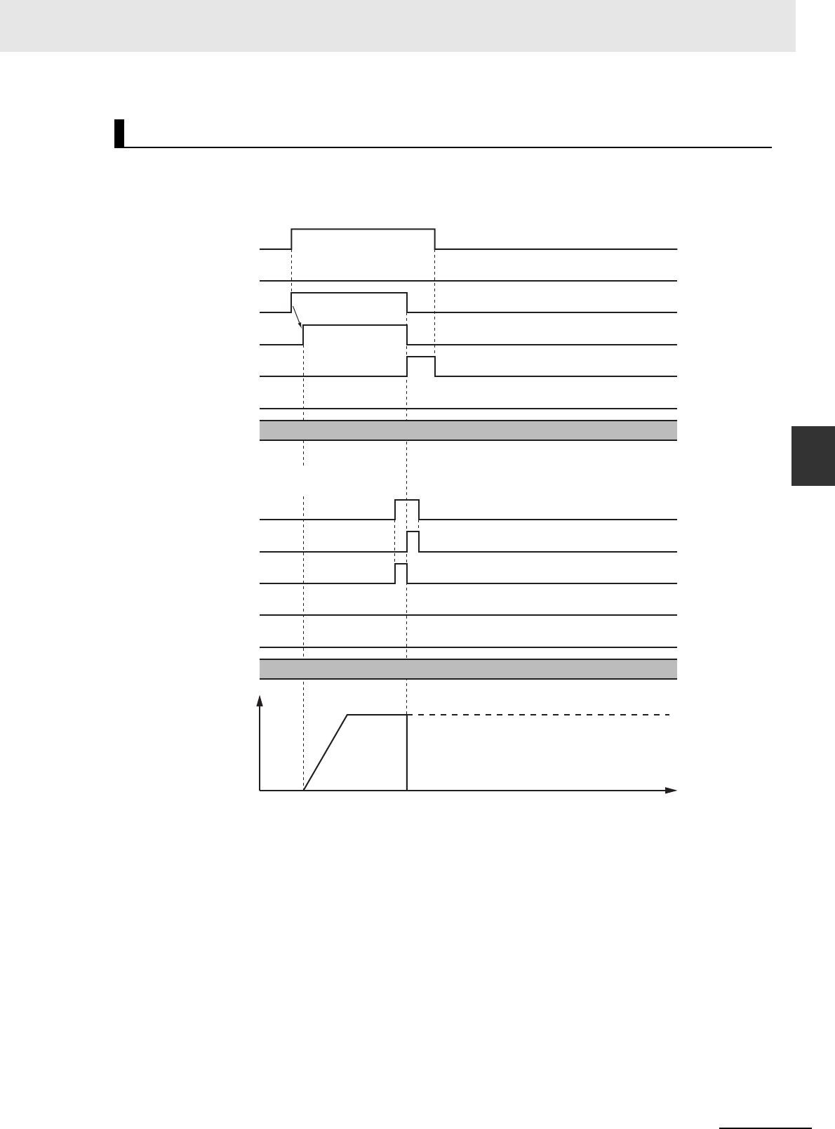
4-77
4 Axes Group Instructions
NJ/NX-series Motion Control Instructions Reference Manual (W508)
MC_GroupImmediateStop
4
Function
• Busy (Executing) changes to TRUE when Execute changes to TRUE.
• Done changes to TRUE when processing of this instruction is completed.
Timing Charts
Busy
Done
CommandAborted
Active
Error
16#0000
ErrorID
Execute
Busy
Done
CommandAborted
Error
16#0000
ErrorID
Execute
Interpolation velocity
Time
MC_MoveLiner Instruction
MC_GroupImmediateStop Instruction

4 Axes Group Instructions
4-78
NJ/NX-series Motion Control Instructions Reference Manual (W508)
This instruction cannot be re-executed.
A Motion Control Instruction Re-execution Disabled error (error code: 543B hex) occurs if re-execution
is attempted, and the axis stops.
For details on multi-execution of motion control instructions, refer to the NJ/NX-series CPU Unit Motion
Control User’s Manual (Cat. No. W507) or NY-series Industrial Panel PC / Industrial Box PC Motion
Control User’s Manual (Cat. No. W559).
Execution during Execution of Other Instructions
When the Axes Group Is Disabled
An axes group error will occur if this instruction is executed for a disabled axes group. However, this
will not affect the axes.
When the Status.Stopping (Deceleration Stopping) in the Axes Group
Variable Is TRUE
Status.Stopping (Deceleration Stopping) in the Axes Group Variable changes to TRUE in the follow-
ing cases.
• While the axis is decelerating for the MC_GroupStop Instruction
• While Execute is TRUE for one or more MC_GroupStop instructions
You can execute this instruction for an axes group that is currently decelerating to a stop.
When this instruction is executed, CommandAborted for the MC_GroupStop instruction that is in
operation will change to TRUE.
When the Status.ErrorStop (Error Deceleration Stopping) in the Axes Group
Variable Is TRUE
Status.ErrorStop (Error Deceleration Stopping) in the axes group status is TRUE while there is an
error for the axes group. You can also execute this instruction for an axes group that is decelerating
to a stop for an error.
If an error occurs during instruction execution, Error will change to TRUE and the axis will stop.
You can find out the cause of the error by referring to the value output by ErrorID (Error Code).
Error Codes
Refer to A-1 Error Codes for instruction errors.
Re-execution of Motion Control Instructions
Multi-execution of Motion Control Instructions
Errors

4-79
4 Axes Group Instructions
NJ/NX-series Motion Control Instructions Reference Manual (W508)
MC_GroupSetOverride
4
Variables
MC_GroupSetOverride
The MC_GroupSetOverride instruction changes the combined target velocity during an interpolated
motion.
Instruction Name
FB/
FUN
Graphic expression ST expression
MC_GroupSetOverride Set Group
Overrides
FB MC_GroupSetOverride_
instance (
AxesGroup :=parameter,
Enable :=parameter,
VelFactor :=parameter,
AccFactor :=parameter,
JerkFactor :=parameter,
Enabled =>parameter,
Busy =>parameter,
Error =>parameter,
ErrorID =>parameter
);
Variables
Input Variables
Name Meaning Data type Valid range Default Description
Enable Enable BOOL TRUE or FALSE FALSE The override factors are
enabled when Enable is TRUE.
The override factors return to
100% when Enable changes to
FALSE.
VelFactor Velocity
Override
Factor
LREAL 0 to 500 100 Specify the velocity override fac-
tor. The valid range of the over-
ride factor is between 0.01and
500.00.
Values above 500.00 are
treated as 500 and values less
than 0.01 (including negative
values) are treated as 0.01.
The override factor will be 0 only
when 0 is specified.
The unit is %.
AccFactor
(Reserved)
Acceleration/
Deceleration
Override
Factor
LREAL 0 to 500 100 (Reserved)
JerkFactor
(Reserved)
Jerk Override
Factor
LREAL 0 to 500 100 (Reserved)
MC_GroupSetOverride_instance
AxesGroup AxesGroup
Enable Enabled
VelFactor
JerkFactor
Error
ErrorID
MC_GroupSetOverride
AccFactor
Busy

4 Axes Group Instructions
4-80
NJ/NX-series Motion Control Instructions Reference Manual (W508)
* Refer to A-1 Error Codes.
Output Variable Update Timing
* Specify a user-defined Axes Group Variable that was created in the Axes Group Basic Settings of the Sysmac Studio
(default: MC_Group***) or a system-defined axes group variable name (_MC_GRP[*], _MC1_GRP[*], or _MC2_GRP[*]).
• This instruction changes the override factors related to the interpolation target velocity for the group
controlled by the next instruction. Changes the target velocity of the axes in operation by changing
the override.
The override factors apply to the following instructions.
• The following is the new target velocity.
Target velocity after the change = Interpolation velocity of the current instruction × Override factor (%)
• The unit for override factors is %. A setting of 100 indicates 100%.
• If the interpolation velocity that results from the override exceeds the maximum interpolation velocity
set in the Axes Group Variables, the maximum interpolation velocity is used.
• The axis will accelerate or decelerate to the interpolation velocity that results from the override.
• If the velocity override factor is set to 0, the target velocity will be 0. Axes group operation will deceler-
ate to a velocity of 0, and operation will continue. Status.Moving in the Axes Group Variable is TRUE
during axes group motion. If you want to pause the axis motion while keeping the operation status,
set the override factor to 0.
• The override factors will return to 100% when Enable changes to FALSE.
Output Variables
Name Meaning Data type Valid range Description
Enabled Enabled BOOL TRUE or
FALSE
TRUE when the axes group is being controlled.
Busy Executing BOOL TRUE or
FALSE
TRUE when the instruction is acknowledged.
Error Error BOOL TRUE or
FALSE
TRUE while there is an error.
ErrorID Error Code WORD
*
Contains the error code when an error occurs. A value
of 16#0000 indicates normal execution.
Name Timing for changing to TRUE Timing for changing to FALSE
Enabled When this instruction is started. • After one period when Enable is FALSE.
• When Error changes to TRUE.
Busy When Enable changes to TRUE. • When Error changes to TRUE.
Error When there is an error in the execution condi-
tions or input parameters for the instruction.
When the error is cleared.
In-Out Variables
Name Meaning Data type Valid range Description
AxesGroup Axes Group _sGROUP_REF ---
Specify the axes group.
*
Function
MC_MoveLinear (Linear Interpolation) instruc-
tion
MC_MoveLinearRelative (Relative Linear Interpolation)
instruction
MC_MoveLinearAbsolute (Absolute Linear
Interpolation) instruction
MC_MoveCircular2D (Circular 2D Interpolation) instruction

4-81
4 Axes Group Instructions
NJ/NX-series Motion Control Instructions Reference Manual (W508)
MC_GroupSetOverride
4
Function
• If an axes group error occurs during MC_GroupSetOverride execution, the value of Enabled for
MC_GroupSetOverride is maintained.
Precautions for Correct UsePrecautions for Correct Use
When Enable to this instruction changes to FALSE, Enabled and Busy from this instruction
change to FALSE.
The axis will accelerate or decelerate to a velocity with a 100% override factor.
Additional Information
Influence on Other Instructions
Use this instruction to temporarily change the target velocities of other instructions. This instruc-
tion does nothing for instructions to which a target velocity is not input. However, Enabled
remains TRUE even if the MC_GroupSetOverride instruction is executed for an instruction to
which it does not apply.
Using this Instruction for the MC_MoveLinear (Linear Interpolation)
Instruction
Timing Charts
Time
Override factor: 50%
Override factor: 100%
Override factor: 200%
Interpolation velocity
Current Instruction
Previous Instruction: MC_MoveLinear
Busy
Execute
CommandAborted
Done
Active
Enabled
Enable
VelFactor
Busy
100 200 50
When overrides are disabled with
MC_GroupSetOverride, the target
velocity returns to 100%.

4 Axes Group Instructions
4-82
NJ/NX-series Motion Control Instructions Reference Manual (W508)
You cannot re-execute enable-type motion control instructions.
For details on multi-execution of motion control instructions, refer to the NJ/NX-series CPU Unit Motion
Control User’s Manual (Cat. No. W507) or NY-series Industrial Panel PC / Industrial Box PC Motion
Control User’s Manual (Cat. No. W559).
Execution of Other Instructions during Instruction Execution
If another instance of the MC_GroupSetOverride instruction is executed during MC_GroupSetOver-
ride execution for the same axes group, the last instance that is executed takes priority in process-
ing.
Enabled will be TRUE for both instructions.
Concretely, the override values of the instance that was executed last are valid. If Enable to the
instance that was executed last changes to FALSE, the overrides are disabled.
If an error occurs during instruction execution, Error will change to TRUE. If an axes group minor fault
occurs, the axes group will stop. You can find out the cause of the error by referring to the value output
by ErrorID (Error Code).
Error Codes
Refer to A-1 Error Codes for instruction errors.
Re-execution of Motion Control Instructions
Multi-execution of Motion Control Instructions
Errors
Error code
Override factor: 200%
Override factor: 100%
Velocity
Time
Enabled
VelFactor
Busy
Enable
200
Error
ErrorID
16#0000

4-83
4 Axes Group Instructions
NJ/NX-series Motion Control Instructions Reference Manual (W508)
MC_GroupReadPosition
4
Variables
MC_GroupReadPosition
The MC_GroupReadPosition instruction gets the command current positions and the actual current
positions of an axes group.
Version Information
A CPU Unit with unit version 1.01 or later and Sysmac Studio version 1.02 or higher are required
to use this instruction.
* The default value for an enumeration variable is actually not the number, but the enumerator.
Instruction Name FB/FUN Graphic expression ST expression
MC_GroupRead
Position
Read Axes
Group
Position
FB MC_GroupReadPosition_instance (
AxesGroup :=parameter,
Enable :=parameter,
CoordSystem :=parameter,
Valid =>parameter,
Busy =>parameter,
Error =>parameter,
ErrorID =>parameter,
CommandPosition =>parameter,
ActualPosition =>parameter,
);
Variables
Input Variables
Name Meaning Data type Valid range Default Description
Enable Enable BOOL TRUE or FALSE FALSE The instruction is executed when
Enable changes to TRUE.
CoordSystem Coordinate
System
_eMC_COOR-
D_SYSTEM
0: _mcACS
0
*
Specify the coordinate system.
0: Axis coordinate system (ACS)
MC_GroupReadPosition_instance
AxesGroup AxesGroup
Enable Valid
CoordSystem
CommandPosition
ActualPosition
ErrorID
MC_GroupReadPosition
Busy
Error

4 Axes Group Instructions
4-84
NJ/NX-series Motion Control Instructions Reference Manual (W508)
*1 Refer to A-1 Error Codes.
*2 Refer to Unit Conversion Settings in the NJ/NX-series CPU Unit Motion Control User’s Manual (Cat. No. W507) or NY-
series Industrial Panel PC / Industrial Box PC Motion Control User’s Manual (Cat. No. W559) for information on command
units.
Note 1 When the axis composition of the axes group contains two or three axes, the values in CommandPosition (Command
Current Position) and ActualPosition (Actual Current Position) for the composition axes that are not used are not
defined.
2 When Enable changes to FALSE, the values in CommandPosition (Command Current Position) and ActualPosition
(Actual Current Position) are not defined.
Output Variable Update Timing
* Specify a user-defined Axes Group Variable that was created in the Axes Group Basic Settings of the Sysmac Studio
(default: MC_Group***) or a system-defined axes group variable name (_MC_GRP[*], _MC1_GRP[*], or _MC2_GRP[*]).
Output Variables
Name Meaning Data type Valid range Description
Valid Enabled BOOL TRUE or
FALSE
TRUE when the axis group is being controlled.
Busy Executing BOOL TRUE or
FALSE
TRUE when the instruction is acknowledged.
Error Error BOOL TRUE or
FALSE
TRUE while there is an error.
ErrorID Error Code WORD
*1
Contains the error code when an error occurs. A value
of 16#0000 indicates normal execution.
CommandPosition Command
Current Posi-
tion
ARRAY
[0..3]OF
LREAL
Negative
number,
positive
number, or 0
Contains the current value of the command position.
The unit is command units.
*2
ActualPosition Actual Current
Position
ARRAY
[0..3]OF
LREAL
Negative
number,
positive
number, or 0
Contains the actual current position.
The unit is command units.
*1
Name Timing for changing to TRUE Timing for changing to FALSE
Valid When Enable changes to TRUE. • When Enable changes to FALSE.
• When Error changes to TRUE.
Busy When Enable changes to TRUE. When Error changes to TRUE.
Error When there is an error in the execution condi-
tions or input parameters for the instruction.
When the error is cleared.
In-Out Variables
Name Meaning Data type Valid range Description
AxesGroup Axes Group _sGROUP_REF ---
Specify the axes group.
*

4-85
4 Axes Group Instructions
NJ/NX-series Motion Control Instructions Reference Manual (W508)
MC_GroupReadPosition
4
Function
• While Valid (Enabled) is TRUE, the MC_GroupReadPosition instruction gets the command current
positions and the actual current positions of the composition axes in the axes group each control
period.
• The following table lists the position types that can be used for each axis type.
* For a virtual servo axis, the actual position is the same as the command position. However, there is sometimes
calculation error because processing is performed with long reals in the MC Function Module.
• You can execute this instruction even if home is not defined.
• You can execute this instruction regardless of whether the axes group is enabled or disabled.
Precautions for Correct UsePrecautions for Correct Use
Before you use this instruction in a task to which the axes group is not assigned, declare Axis
Variables as external variables for the configuration axes that are specified in Axes (Axes Group
Composition Axes) in the task.
• When Enable changes to TRUE, Busy (Executing) and Valid (Enabled) change to TRUE.
When Enable changes to FALSE, Busy (Executing) and Valid (Enabled) change to FALSE.
You cannot re-execute enable-type motion instructions.
Function
Axis type
Types of positions
Command current position Actual current position
Servo axis Applicable Applicable
Virtual servo axis Applicable
Applicable
*
Encoder axis Not applicable Applicable
Virtual encoder axis Not applicable Applicable
Timing Charts
Re-execution of Motion Control Instructions
MC_GroupReadPosition
Enable
Valid
Busy
Error
Error ID
CommandPosition
/ActualPosition
10 20 30 40 40 40 30 20 20
UndefinedUndefined
16#0000

4 Axes Group Instructions
4-86
NJ/NX-series Motion Control Instructions Reference Manual (W508)
This instruction is executed independently from other instructions. The restrictions for multi-execution of
instructions do not apply.
For details on multi-execution of motion control instructions, refer to the NJ/NX-series CPU Unit Motion
Control User’s Manual (Cat. No. W507) or NY-series Industrial Panel PC / Industrial Box PC Motion
Control User’s Manual (Cat. No. W559).
If an error occurs during instruction execution, Error will change to TRUE.
You can find out the cause of the error by referring to the value output by ErrorID (Error Code).
Error Codes
Refer to A-1 Error Codes for instruction errors.
Multi-execution of Motion Control Instructions
Errors
MC_GroupReadPosition
Enable
Busy
Valid
Error
ErrorID
16#0000 Error Code

4-87
4 Axes Group Instructions
NJ/NX-series Motion Control Instructions Reference Manual (W508)
MC_ChangeAxesInGroup
4
Variables
MC_ChangeAxesInGroup
The MC_ChangeAxesInGroup instruction temporarily changes the Composition Axes axes group
parameter.
Precautions for Correct UsePrecautions for Correct Use
The values that are written by this instruction are not saved in non-volatile memory in the CPU
Unit. Any values that are written are lost when the power supply to the Controller is turned OFF,
when settings are downloaded, or when the MC Function Module is restarted. They return to the
values that were set from the Sysmac Studio. Use the Sysmac Studio and transfer the parame-
ters to save them to non-volatile memory.
Additional Information
Use the Synchronize Menu of the Sysmac Studio to download the project.
Version Information
A CPU Unit with unit version 1.01 or later and Sysmac Studio version 1.02 or higher are required
to use this instruction.
Instruction Name FB/FUN Graphic expression ST expression
MC_Change
AxesInGroup
Change
Axes in
Group
FB MC_ChangeAxesInGroup_instance (
AxesGroup :=parameter,
Axes :=parameter,
Execute :=parameter,
Done =>parameter,
Busy =>parameter,
CommandAborted =>parameter,
Error =>parameter,
ErrorID =>parameter,
);
Variables
Input Variables
Name Meaning Data type Valid range Default Description
Execute Execute BOOL TRUE or FALSE FALSE The instruction is executed when
Execute changes to TRUE.
MC_ChangeAxesInGroup_instance
AxesGroup AxesGroup
Axes Axes
Execute
Error
ErrorID
CommandAborted
MC_ChangeAxesInGroup
Done
Busy

4 Axes Group Instructions
4-88
NJ/NX-series Motion Control Instructions Reference Manual (W508)
* Refer to A-1 Error Codes.
Output Variable Update Timing
*1 Specify a user-defined Axes Group Variable that was created in the Axes Group Basic Settings of the Sysmac Studio
(default: MC_Group***) or a system-defined axes group variable name (_MC_GRP[*], _MC1_GRP[*], or _MC2_GRP[*]).
*2 Set only servo axes or virtual servo axes as the composition axes. Specify the same number of composition axes as the
number before the composition axes are changed.
Output Variables
Name Meaning Data type Valid range Description
Done Done BOOL TRUE or
FALSE
TRUE when instruction execution is completed.
Busy Executing BOOL TRUE or
FALSE
TRUE when the instruction is acknowledged.
CommandAborted Instruction
Aborted
BOOL TRUE or
FALSE
TRUE when the instruction is aborted.
Error Error BOOL TRUE or
FALSE
TRUE while there is an error.
ErrorID Error Code WORD
*
Contains the error code when an error occurs.
A value of 16#0000 indicates normal execution.
Name Timing for changing to TRUE Timing for changing to FALSE
Done When the instruction is completed. • When Execute is TRUE and changes to
FALSE.
• After one period when Execute is FALSE.
Busy When Execute changes to TRUE. • When Done changes to TRUE.
• When Error changes to TRUE.
• When CommandAborted changes to TRUE.
CommandAborted When another instruction causes an error and
aborts this instruction.
• When Execute is TRUE and changes to
FALSE.
• After one period when Execute is FALSE.
Error When there is an error in the execution condi-
tions or input parameters for the instruction.
When the error is cleared.
In-Out Variables
Name Meaning Data type Valid range Description
Axes Group Axes Group _sGROUP_REF --- Specify the axes group for which to
change the axes.
*1
Axes Axes Group
Composition
Axes
ARRAY [0..3]OF UINT --- Specify the axis numbers of the new
composition axes.
*2

4-89
4 Axes Group Instructions
NJ/NX-series Motion Control Instructions Reference Manual (W508)
MC_ChangeAxesInGroup
4
Function
• When Execute changes to TRUE, the MC_ChangeAxesInGroup instruction writes the composition
axes that are specified in Axes (Axes Group Composition Axes) to the Axes Group parameter for the
axes group that is specified in AxesGroup (Axes Group).
• When execution of the instruction is completed, Axis[ ] in the Kinematics (Kinematics Transformation
Settings) axes group variable will indicate the specified composition axes.
• You cannot use this instruction to change the axis composition (i.e., the number of axes). For exam-
ple, if you execute this instruction for an axes group with an axis composition of three axes, the axis
composition will still contain three axes.
• The operation for changing the axes numbers of the composition axes from 0, 1, 2, and 3 to 7, 6, 5,
and 4 is illustrated below.
• You can execute this instruction regardless of whether home is defined.
• You can execute this instruction only when the axes group is disabled.
Precautions for Correct UsePrecautions for Correct Use
• The values that are written by this instruction are not saved in non-volatile memory in the CPU
Unit. Any values that are written are lost when the power supply to the Controller is turned
OFF, when settings are downloaded, or when the MC Function Module is restarted. They
return to the values that were set from the Sysmac Studio. Use the Sysmac Studio and trans-
fer the parameters to save them to non-volatile memory.
• If you use an NX-series CPU Unit, you must assign all of the composition axes specified in
Axes (Axes Group Composition Axes) to the same task as the Axes Group for which to exe-
cute the instruction. If you specify an axis that is assigned to a different task, an Axes Group
Composition Axis Setting Out of Range error (error code 549D hex) occurs.
• When Execute changes to TRUE, Busy (Executing) changes to TRUE.
• Done changes to TRUE when changing the composition axes is completed.
Function
Timing Charts
Execute
Done
Axes[0]
Axes[1]
Axes[2]
Axes[3]
Kinematics.Axes[0]
Kinematics.Axes[1]
Kinematics.Axes[2]
Kinematics.Axes[3]
UINT#7
UINT#6
UINT#5
UINT#4
UINT#1
UINT#2
UINT#3
UINT#0 UINT#7
UINT#6
UINT#5
UINT#4

4 Axes Group Instructions
4-90
NJ/NX-series Motion Control Instructions Reference Manual (W508)
This instruction cannot be re-executed.
A Motion Control Instruction Re-execution Disabled error (error code: 543B hex) occurs if re-execution
is attempted.
For details on multi-execution of motion control instructions, refer to the NJ/NX-series CPU Unit Motion
Control User’s Manual (Cat. No. W507) or NY-series Industrial Panel PC / Industrial Box PC Motion
Control User’s Manual (Cat. No. W559).
If an error occurs during instruction execution, Error will change to TRUE.
The parameter is not changed, i.e., the previous values are retained.
You can find out the cause of the error by referring to the value output by ErrorID (Error Code).
Timing Chart When Error Occurs
Error Codes
Refer to A-1 Error Codes for instruction errors.
Re-execution of Motion Control Instructions
Multi-execution of Motion Control Instructions
Errors
Done
Busy
CommandAborted
Error
ErrorID
Execute
16#0000
MC_ChangeAxesInGroup Instruction
Busy
Execute
CommandAborted
Done
Error
ErrorID
Error code

4-91
4 Axes Group Instructions
NJ/NX-series Motion Control Instructions Reference Manual (W508)
MC_GroupSyncMoveAbsolute
4
Variables
MC_GroupSyncMoveAbsolute
The MC_GroupSyncMoveAbsolute instruction cyclically outputs the specified target positions for the
axes.
Version Information
A CPU Unit with unit version 1.01 or later and Sysmac Studio version 1.02 or higher are required
to use this instruction.
*1 Refer to Unit Conversion Settings in the NJ/NX-series CPU Unit Motion Control User’s Manual (Cat. No. W507) or NY-
series Industrial Panel PC / Industrial Box PC Motion Control User’s Manual (Cat. No. W559) for information on command
units.
*2 The default value for an enumeration variable is actually not the number, but the enumerator.
Instruction Name FB/FUN Graphic expression ST expression
MC_GroupSyn-
cMoveAbsolute
Axes Group
Cyclic Syn-
chronous
Absolute
Positioning
FB MC_GroupSyncMoveAbsolute
_instance (
AxesGroup :=parameter,
Execute :=parameter,
Position :=parameter,
CoordSystem :=parameter,
BufferMode :=parameter,
InPosition =>parameter,
Busy =>parameter,
Active =>parameter,
CommandAborted
=>parameter,
Error =>parameter,
ErrorID =>parameter,
);
Variables
Input Variables
Name Meaning Data type Valid range Default Description
Execute Execute BOOL TRUE or FALSE FALSE The instruction is executed when
Execute changes to TRUE.
Position Target Posi-
tion
ARRAY [0..3]
OFLREAL
Negative number,
positive number, or 0
0 Specify the absolute target posi-
tions.
The unit is command units.
*1
CoordSystem Coordinate
System
_eMC_COOR-
D_SYSTEM
0: _mcACS
0
*2
Specify the coordinate system.
0: Axis coordinate system (ACS)
BufferMode Buffer Mode
Selection
_eM-
C_BUFFER_-
MODE
0: _mcAborting 0 Specify the behavior when exe-
cuting more than one motion
instruction.
0: Aborting
MC_GroupSyncMoveAbsolute_instance
AxesGroup AxesGroup
Execute InPosition
Position
BufferMode
Error
ErrorID
CommandAborted
Active
MC_GroupSyncMoveAbsolute
CoordSystem
Busy

4 Axes Group Instructions
4-92
NJ/NX-series Motion Control Instructions Reference Manual (W508)
* Refer to A-1 Error Codes.
Output Variable Update Timing
* Specify a user-defined Axes Group Variable that was created in the Axes Group Basic Settings of the Sysmac Studio
(default: MC_Group***) or a system-defined axes group variable name (_MC_GRP[*], _MC1_GRP[*], or _MC2_GRP[*]).
Output Variables
Name Meaning Data type Valid range Description
InPosition In Position BOOL TRUE or
FALSE
TRUE when the actual current positions for all composi-
tion axes are within the in-position range of their target
positions.
Busy Executing BOOL TRUE or
FALSE
TRUE when the instruction is acknowledged.
Active Controlling BOOL TRUE or
FALSE
TRUE when the axis is being controlled.
CommandAborted Instruction
Aborted
BOOL TRUE or
FALSE
TRUE when the instruction is aborted.
Error Error BOOL TRUE or
FALSE
TRUE while there is an error.
ErrorID Error Code WORD
*
Contains the error code when an error occurs.
A value of 16#0000 indicates normal execution.
Name Timing for changing to TRUE Timing for changing to FALSE
InPosition When the actual current positions for all com-
position axes are within the in-position range of
their target positions.
• When an actual current position is outside of
the in-position range.
• When Error changes to TRUE.
• When CommandAborted changes to TRUE.
Busy When Execute changes to TRUE. • When Error changes to TRUE.
• When CommandAborted changes to TRUE.
Active When the instruction is started. • When Error changes to TRUE.
• When CommandAborted changes to TRUE.
CommandAborted • When this instruction is aborted because
another motion control instruction was exe-
cuted with the Buffer Mode set to Aborting.
• When this instruction is canceled due to an
error in another instruction.
• When this instruction is executed while there
is an axis error.
• When you start this instruction during
MC_GroupStop instruction execution.
• When Execute is TRUE and changes to
FALSE.
• After one period when Execute is FALSE.
Error When there is an error in the execution condi-
tions or input parameters for the instruction.
When the error is cleared.
In-Out Variables
Name Meaning Data type Valid range Description
Axes Group Axes Group _sGROUP_REF ---
Specify the axes group.
*

4-93
4 Axes Group Instructions
NJ/NX-series Motion Control Instructions Reference Manual (W508)
MC_GroupSyncMoveAbsolute
4
Function
• The MC_GroupSyncMoveAbsolute instruction outputs the target position from the user program
every task period to the Servo Drive or other device in Cyclic Synchronous Position (CSP) Control
Mode. The target positions are given as absolute positions.
• The upper limit of the velocity is the value that is set in the Maximum Velocity axis parameter. The
maximum acceleration and deceleration rates are not used.
• If this instruction is executed in the primary periodic task or priority-5 periodic task, the target position
that is specified in the input parameters is output to the Servo Drive in the next task period.
The following timing charts show an example of the operation for when this instruction is executed in
the primary periodic task. The same information applies when it is used in a priority-5 periodic task.
• If this instruction is executed in the priority-16 periodic task, the target positions that are specified in
the input parameters are output to the Servo Drive in the next periodic task.
Precautions for Correct UsePrecautions for Correct Use
• An Instruction Execution Error with Undefined Home (error code: 5466 hex) occurs if home is
undefined for any of the composition axes in the axes group.
• Specify the target positions so that the travel distances to the target positions do not cause the
velocity to exceed the value that is specified in the Maximum Velocity axis parameter. If target
positions are specified that cause the maximum velocity to be exceeded, the command veloc-
ity will become saturated and the travel distances will be output so that the maximum velocity
is not exceeded. If this occurs, any insufficient travel distances to the target positions are out-
put in the next period or later. Details.VelLimit (Command Velocity Saturation) in the axis con-
trol status changes to TRUE at this time.
Function
M
E
MC_GroupSyncMoveAbsolute Executed
in Primary Periodic Task
Command
positions
Time
Primary period
Command position
Position
Servo Drive
Target positions (black
dots) specified with the
input parameters
M
E
MC_GroupSyncMoveAbsolute Executed
in Priority-16 Periodic Task
Command
positions
Time
Primary period
Command position
Position
Servo Drive
Target positions (black
dots) specified with the
input parameters
Task period

4 Axes Group Instructions
4-94
NJ/NX-series Motion Control Instructions Reference Manual (W508)
This section describes the instruction in detail.
In-position Check
If Position (Target Position) is not changed, InPosition changes to TRUE when the difference between
the target position and the actual position is within the range that is set for the In-position Range axis
parameter.
Even if the target position is changed while InPosition is TRUE, it will remain TRUE for the remainder of
the period and change to FALSE the next period.
The setting of the In-position Check Time axis parameter is disabled.
Stop Processing
This section describes the methods that are used to stop axes group operations.
Use the MC_GroupStop instruction or the MC_GroupImmediateStop instruction to stop axes group
operation. If one of these instructions is executed, CommandAborted for this instruction will change
to TRUE.
Stopping with the MC_GroupStop Instruction
An immediate stop is performed.
Stopping with the MC_GroupImmediateStop Instruction
An immediate stop is performed according to the setting of the Immediate Stop Input Stop Method
axis parameter for each axis.
Stopping Due to Errors
If an error that causes the axes to stop occurs, an immediate stop is performed regardless of any
settings.
Applicable Axes
• You can use this instruction for a servo axis.
To use this instruction, change Enable for the MC_Power instruction to TRUE (Servo ON).
• A virtual servo axis will acknowledge this instruction at any time.
Start Condition
• Set the Count Mode axis parameters to Linear Mode.
• Define home for all of the composition axes.
• Execute the MC_GroupEnable instruction to enable the axes group.
Axis Variable Status
Status.Moving in the Axes Group Variable is TRUE during axes group motion.
The Axes Group Control Status is not affected.
Override Factors
Overrides are disabled for this instruction.
Instruction Details

4-95
4 Axes Group Instructions
NJ/NX-series Motion Control Instructions Reference Manual (W508)
MC_GroupSyncMoveAbsolute
4
Function
• Busy (Executing) changes to TRUE at the same time as Execute changes to TRUE. Active (Con-
trolling) changes to TRUE in the next period.
• InPosition changes to TRUE when the actual current positions for all composition axes are within the
in-position range from Positions (Target Positions).
• If another instruction aborts this instruction, CommandAborted changes to TRUE and Busy (Execut-
ing), Active (Controlling), and InPosition change to FALSE.
• The MC_GroupStop instruction is used to stop this instruction.
The following timing charts show operation for when this instruction is executed in the primary periodic
task.
Additional Information
The MC Function Module sends a command to the Servo Drive to change the Control Mode as
shown in the above timing chart. The timing of implementing the change in the Servo Drive
depends on Servo Drive specifications.
Timing Charts
Busy
InPosition
Position
CommandAborted
Active
Error
ErrorID
Execute
Busy
Done
Active
60
50
40
30
20
0
Execute
20 30 40 50 60 40
16#0000
Command position
Time
MC_GroupSyncMoveAbsolute Instruction
MC_GroupStop Instruction

4 Axes Group Instructions
4-96
NJ/NX-series Motion Control Instructions Reference Manual (W508)
This instruction cannot be re-executed.
A Motion Control Instruction Re-execution Disabled error (error code: 543B hex) occurs if re-execution
is attempted.
For details on multi-execution of motion control instructions, refer to the NJ/NX-series CPU Unit Motion
Control User’s Manual (Cat. No. W507) or NY-series Industrial Panel PC / Industrial Box PC Motion
Control User’s Manual (Cat. No. W559).
Execution during Execution of Other Instructions
BufferMode can be set only to Aborting for this instruction.
Execution of Other Instructions during Instruction Execution
If you execute another instruction during execution of this instruction, you can specify only aborting.
If an error occurs during instruction execution, Error will change to TRUE and the axes will stop.
You can find out the cause of the error by referring to the value output by ErrorID (Error Code).
Timing Chart When Error Occurs
Error Codes
Refer to A-1 Error Codes for instruction errors.
Re-execution of Motion Control Instructions
Multi-execution of Motion Control Instructions
Errors
Busy
CommandAborted
InPosition
Error
16#0000
ErrorID
Execute
Active
Error code

4-97
4 Axes Group Instructions
NJ/NX-series Motion Control Instructions Reference Manual (W508)
MC_GroupReset
4
Variables
MC_GroupReset
The MC_GroupReset instruction clears axes group errors and axis errors.
*Refer to A-1 Error Codes.
Instruction Name FB/FUN Graphic expression ST expression
MC_GroupReset Group Reset FB MC_GroupReset_instance (
AxesGroup :=parameter,
Execute :=parameter,
Done =>parameter,
Busy =>parameter,
Failure =>parameter,
Error =>parameter,
ErrorID =>parameter
);
Variables
Input Variables
Name Meaning Data type Valid range Default Description
Execute Execute BOOL TRUE or FALSE FALSE The instruction is executed when
Execute changes to TRUE.
Output Variables
Name Meaning Data type Valid range Description
Done Done BOOL TRUE or
FALSE
TRUE when the instruction is completed.
Busy Executing BOOL TRUE or
FALSE
TRUE when the instruction is acknowledged.
Failure Failure End BOOL TRUE or
FALSE
TRUE when the instruction was not executed correctly.
Error Error BOOL TRUE or
FALSE
TRUE while there is an error.
ErrorID Error Code WORD
*
Contains the error code when an error occurs. A value
of 16#0000 indicates normal execution.
MC_GroupReset_instance
Failure
AxesGroup AxesGroup
Execute
Error
ErrorID
MC_GroupReset
Done
Busy

4 Axes Group Instructions
4-98
NJ/NX-series Motion Control Instructions Reference Manual (W508)
Output Variable Update Timing
* Specify a user-defined Axes Group Variable that was created in the Axes Group Basic Settings of the Sysmac Studio
(default: MC_Group***) or a system-defined axes group variable name (_MC_GRP[*], _MC1_GRP[*], or _MC2_GRP[*]).
• When Execute changes to TRUE, the error of the axes group specified by AxesGroup in the
GroupEnable state and axis errors of axes belonging to the axes group are cleared.
The following are reset: minor faults or observations that occur for axes or axes groups and drive
errors.
• Error clear processing is performed regardless of whether the Servo is ON or OFF for the axes.
• If there is a drive error for an axis, the drive error is cleared first. Error clear processing is then per-
formed.
• Reset processing for the drive error is continued until the drive error is cleared or continues for the
Drive Error Reset Monitoring Time in the axis parameters. The drive error reset process is executed
for all axes belonging to the axes group at the same time.
• Only errors that existed when Execute changed to TRUE are reset. Errors that occur while clearing
errors are not cleared.
• If this instruction is executed while the axes group is decelerating to a stop for an axes group error
and the instruction is not executed, Failure will change to TRUE. This is so that the error cannot be
reset before the axis stops. Failure will also change to TRUE if an axis error that results from an axis
common error cannot be cleared by this instruction.
Name Timing for changing to TRUE Timing for changing to FALSE
Done When error clear processing is completed nor-
mally.
• When Execute is TRUE and changes to
FALSE.
• After one period when Execute is FALSE.
Busy When Execute changes to TRUE. • When Done changes to TRUE.
• When Error changes to TRUE.
• When Failure changes to TRUE.
Failure • When an instruction is executed while an
axis or axes group is decelerating to a stop
caused by an error.
• When an instruction is executed while there
is an axes group error that is caused by an
axis common error.
• When Execute is TRUE and changes to
FALSE.
• After one period when Execute is FALSE.
Error When there is an error in the execution condi-
tions or input parameters for the instruction.
When the error is cleared.
In-Out Variables
Name Meaning Data type Valid range Description
AxesGroup Axes Group _sGROUP_REF ---
Specify the axes group.
*
Function

4-99
4 Axes Group Instructions
NJ/NX-series Motion Control Instructions Reference Manual (W508)
MC_GroupReset
4
Function
Precautions for Correct UsePrecautions for Correct Use
• The error clear processing that is performed by this instruction sometimes requires more than
one control period.
• The Failure output variable from the instruction will change to TRUE if the axis is in motion.
Remove the cause of the error, and then retry the process until Done changes to TRUE.
• After you remove the cause of the error, execute the instruction only after you confirm that the
axes have stopped completely.
• If you use this instruction for an OMRON G5-series Servo Drive, perform exclusive control of
instructions so that the ResetECError (Reset EtherCAT Error) instruction is not executed at the
same time.
• If this instruction is used for an NX-series Pulse Output Unit, the error in the Servo Drive that is
connected to the Pulse Output Unit is not reset. Refer to the NX-series Position Interface Units
User’s Manual (Cat. No. W524) for details.
Additional Information
• You can clear axis errors only when the axes group is enabled.
• The following errors cannot be cleared with this instruction.
All axis common errors
To clear axis common errors, execute the ResetMcError (Reset All Errors) instruction sepa-
rately.
• If you execute this instruction on an axes group for which there is no error, the instruction is
completed normally and the current status is continued.
Timing Charts
Error code
Instruction Output Parameters during Errors
Busy
Execute
Failure
Done
Busy
Error
ErrorID
16#0000
Active

4 Axes Group Instructions
4-100
NJ/NX-series Motion Control Instructions Reference Manual (W508)
The instruction is aborted if it is not possible to clear errors that occur when the axes group is decelerat-
ing to a stop for an error or errors that occur during axes group errors resulting from axis common
errors.
If the instruction is re-executed by changing Execute to TRUE again, the re-executed instruction is
ignored and error clear processing is continued.
For details on multi-execution of motion control instructions, refer to the NJ/NX-series CPU Unit Motion
Control User’s Manual (Cat. No. W507) or NY-series Industrial Panel PC / Industrial Box PC Motion
Control User’s Manual (Cat. No. W559).
Execution of Other Instructions during Instruction Execution
If another instance of the MC_GroupReset instruction is executed for the same axes group, both
instructions are executed. If a slave error occurs, processing may wait until the Drive Error Reset
Monitoring Time that is set for the axis expires. The elapsed time is counted for each instruction
instance. If MC_Reset (Reset Axis Error) is executed for the axes belonging to the specified axes
group while this instruction is in execution, both instructions are executed.
Aborting the Instruction
Re-execution of Motion Control Instructions
Multi-execution of Motion Control Instructions
Busy
Execute
Failure
Done
The command from re-executing the instruction is not
acknowledged and the current processing is continued.
Busy
Execute
Failure
Done
AxesGroup1
Error
ErrorID
Failure
Execute Done
Busy
MC_GroupReset
Reset A
AxesGroupAxesGroup
Error
ErrorID
Failure
Execute Done
Busy
MC_GroupReset
Reset B
AxesGroupAxesGroup
A
B
Executes multiple
MC_GroupReset instructions
for the same axes group.
AxesGroup1


4 Axes Group Instructions
4-102
NJ/NX-series Motion Control Instructions Reference Manual (W508)

5-1
NJ/NX-series Motion Control Instructions Reference Manual (W508)
5
This section describes the instructions that are used for both axes and axes groups.
MC_SetCamTableProperty . . . . . . . . . . . . . . . . . . . . . . . . . . . . . . . . . . . . . . 5-2
MC_SaveCamTable . . . . . . . . . . . . . . . . . . . . . . . . . . . . . . . . . . . . . . . . . . . . 5-8
MC_Write . . . . . . . . . . . . . . . . . . . . . . . . . . . . . . . . . . . . . . . . . . . . . . . . . . . . 5-12
MC_GenerateCamTable . . . . . . . . . . . . . . . . . . . . . . . . . . . . . . . . . . . . . . . . 5-18
MC_WriteAxisParameter . . . . . . . . . . . . . . . . . . . . . . . . . . . . . . . . . . . . . . . 5-47
MC_ReadAxisParameter . . . . . . . . . . . . . . . . . . . . . . . . . . . . . . . . . . . . . . . 5-62
Common Command Instructions

5 Common Command Instructions
5-2
NJ/NX-series Motion Control Instructions Reference Manual (W508)
MC_SetCamTableProperty
The MC_SetCamTableProperty instruction changes the end point index of the cam table that is speci-
fied in an in-out parameter.
* Refer to A-1 Error Codes.
Instruction Name
FB/
FUN
Graphic expression ST expression
MC_SetCamTableProperty Set Cam
Table Prop-
erties
FB MC_SetCamTableProperty_
instance (
CamTable :=parameter,
Execute :=parameter,
Done =>parameter,
EndPointIndex =>parameter,
MaxDataNumber =>parameter,
Busy =>parameter,
CommandAborted =>parameter,
Error =>parameter,
ErrorID =>parameter
);
Variables
Input Variables
Name Meaning Data type Valid range Default Description
Execute Execute BOOL TRUE or FALSE FALSE The instruction is executed when
Execute changes to TRUE.
Output Variables
Name Meaning Data type Valid range Description
Done Done BOOL TRUE or FALSE TRUE when the instruction is completed.
EndPointIndex End Point
Index
UINT Non-negative
number
Contains the cam table end point index.
MaxDataNumber Maximum
Number of
Cam Data
UINT Positive number Contains the maximum number of cam data.
Busy Executing BOOL TRUE or FALSE TRUE when the instruction is acknowledged.
CommandAborted Command
Aborted
BOOL TRUE or FALSE TRUE when the instruction is aborted.
Error Error BOOL TRUE or FALSE TRUE while there is an error.
ErrorID Error Code WORD
*
Contains the error code when an error occurs. A
value of 16#0000 indicates normal execution.
MC_SetCamTableProperty_instance
MaxDataNumber
CamTable CamTable
EndPointIndex
Execute
Error
ErrorID
CommandAborted
MC_SetCamTableProperty
Done
Busy

5-3
5 Common Command Instructions
NJ/NX-series Motion Control Instructions Reference Manual (W508)
MC_SetCamTableProperty
5
Function
Output Variable Update Timing
* N in the array variable is set automatically by the Sysmac Studio. Specify a cam data variable that was created on Cam Edi-
tor of the Sysmac Studio.
• The MC_SetCamTableProperty instruction changes the end point index of the cam table that is spec-
ified in an in-out parameter.
• The end point is the data located one cam data before the first cam data with a phase of 0 after the
start point in the cam table.
• The array number of the end point is output to EndPointIndex.
• Any data that is detected after the 0 phase is detected is treated as invalid cam data, and the
phase/displacement values are ignored.
• The maximum number of cam data is the value that was specified when the structure array is
declared with the Sysmac Studio.
• When the user program changes the cam data end point index, the end point must be updated. Use
this instruction to update the number of valid cam data.
For details on cam tables, refer to the NJ/NX-series CPU Unit Motion Control User's Manual (Cat. No.
W507) or NY-series Industrial Panel PC / Industrial Box PC Motion Control User’s Manual (Cat. No.
W559).
Name Timing for changing to TRUE Timing for changing to FALSE
Done When overwriting cam table data is completed. • When Execute is TRUE and changes to FALSE.
• After one period when Execute is FALSE.
Busy When Execute changes to TRUE. • When Done changes to TRUE.
• When Error changes to TRUE.
• When CommandAborted changes to TRUE.
CommandAborted When there is a reason to abort this instruction. • When Execute is TRUE and changes to FALSE.
• After one period when Execute is FALSE.
Error When there is an error in the execution condi-
tions or input parameters for the instruction.
When the error is cleared.
In-Out Variables
Name Meaning Data type Valid range Description
CamTable Cam Table ARRAY[0..N] OF
_sMC_CAM_REF
--- Specify the cam data structure _sMC_CAM_REF
array variable as the cam table.
*
Function

5 Common Command Instructions
5-4
NJ/NX-series Motion Control Instructions Reference Manual (W508)
Precautions for Correct UsePrecautions for Correct Use
• When searching the cam table, an error will occur if the phases are not in ascending order
before the 0 phase is found.
• You cannot change the maximum number of cam data from the user program.
• Execute this instruction after changing the end point in the can data or overwriting values in
the cam data.
If the end point index is not changed or the phases are not in ascending order, the cam opera-
tion and the operation of the EndOfProfile (End of Cam Cycle) of the MC_CamIn (Start Cam
Operation) instruction may not be as expected.
• If the cam table is changed while this instruction is being processed, the update process will
not be performed correctly. Wait for execution of this instruction to be completed before you
change the cam data from the user program.
• Cam data variables are global variables. You can therefore access or change the values of
cam data variables from more than one task. If you change the values of cam data variables
from more than one task, program the changes so that there is no competition in writing the
value from more than one task.
• If you use exclusive control of global variables between tasks for a cam data variable, do not
use the cam data variable for motion control instructions while exclusive control is in effect for
the cam data variable. An Incorrect Cam Table Specification error (error code: 5439 hex) will
occur.
For example, refer to the following cam table. The EndPointIndex is 999 and the MaxDataNumber
(Maximum Number of Cam Data) is 5,000.
Instruction Details
Phase
Displacement
Maximum number
of data: 5,000
Invalid data
End point
Valid data
Start point
Cam data structure array
MyCam1 [0]
MyCam1 [997]
MyCam1 [998]
MyCam1 [999]
MyCam1 [1000]
MyCam1 [4999]
.
.
.
.
.
.
.
.
.
.
.
.
.
.
.
.
.
.
359.8
359.9
360.0
0
0
0
2
1
0
0
0
0

5-5
5 Common Command Instructions
NJ/NX-series Motion Control Instructions Reference Manual (W508)
MC_SetCamTableProperty
5
Function
The following tables show the relationship between overwriting of the cam data and the EndPointIndex.
If this instruction is executed with a cam table in which the phases for MyCam1[1000] on are 0, End-
PointIndex will be 999.
If this instruction is executed for a cam table after the phase for MyCam1[997] is changed to 0, End-
PointIndex will be 996.
Phase
Phase
End point
Invalid data
End point
Cam data structure array
MyCam1 [0]
MyCam1 [995]
MyCam1 [996]
MyCam1 [997]
MyCam1 [998]
MyCam1 [999]
MyCam1 [1000]
MyCam1 [4999]
.
.
.
.
.
.
.
.
.
.
.
.
.
.
.
.
.
.
359.6
359.7
359.8
359.9
360.0
0
0
0
5
4
2
1
0
0
0
0
.
.
.
.
.
.
.
.
.
.
.
.
359.6
360.0
0
359.9
360.0
0
0
0
5
0
0
1
0
0
0
0
Displacement
Displacement

5 Common Command Instructions
5-6
NJ/NX-series Motion Control Instructions Reference Manual (W508)
If this instruction is executed for a cam table after the phases for MyCam1[1000] to MyCam1[4997] are
changed anything other than 0, EndPointIndex will be 4997.
If this instruction is not executed even though the phases for MyCam1[1000] to MyCam1[4997] were
overwritten to values other than 0, cam operation will be executed between MyCam1[0] to MyC-
am1[999]. The cam table is overwritten, but the EndPointIndex does not change.
For information on the cam table data structure, refer to MC_CamIn on page 3-165.
The following chart shows two ways to execute the instruction. A normal end is indicated for either
method.
The first time, Execute is changed to TRUE and then it is changed to FALSE before execution of the
instruction is completed.
The second time, the value of Execute is held.
This instruction cannot be re-executed.
A Motion Control Instruction Re-execution Disabled error (error code: 543B hex) occurs if re-execution
is attempted.
Timing Charts
Re-execution of Motion Control Instructions
Phase Phase
Invalid data
End point
Invalid
data
End point
Cam data structure array
MyCam1 [0]
MyCam1 [998]
MyCam1 [999]
MyCam1 [1000]
MyCam1 [4996]
MyCam1 [4997]
MyCam1 [4998]
MyCam1 [4999]
.
.
.
.
.
.
.
.
.
.
.
.
.
.
.
.
.
.
359.9
360.0
0
0
0
0
0
0
1
0
0
0
.
.
.
.
.
.
.
.
.
.
.
.
100.3
100.4
100.5
359.99
360.00
0
0
0
20.3
20.4
20.5
0
0.01
0.0
0
0
0
0
0
0
Displacement
Displacement
Busy
Execute
CommandAborted
Done
Error
ErrorID
16#0000

5-7
5 Common Command Instructions
NJ/NX-series Motion Control Instructions Reference Manual (W508)
MC_SetCamTableProperty
5
Function
Execution during Execution of Other Instructions
Multi-execution of instructions cannot be used for this instruction if the cam table specified by Cam-
Table is used by another instruction such as MC_SaveCamTable, MC_SetCamTableProperty, or
MC_GenerateCamTable
Execution of Other Instructions during Instruction Execution
Multi-execution of instructions cannot be used for other instructions such as MC_SaveCamTable,
MC_SetCamTableProperty, or MC_GenerateCamTable if the same cam table is specified with Cam-
Table for this instruction.
If an error occurs during instruction execution, Error will change to TRUE. You can find out the cause of
the error by referring to the value output by ErrorID (Error Code).
Error Codes
Refer to A-1 Error Codes for instruction errors.
Multi-execution of Motion Control Instructions
Errors
Error code
Busy
Execute
CommandAborted
Done
Error
ErrorID

5 Common Command Instructions
5-8
NJ/NX-series Motion Control Instructions Reference Manual (W508)
MC_SaveCamTable
The MC_SaveCamTable instruction saves the cam table specified with the input parameter to non-vola-
tile memory.
* Refer to A-1 Error Codes.
Output Variable Update Timing
Instruction Name
FB/
FUN
Graphic expression ST expression
MC_SaveCamTable Save Cam
Table
FB MC_SaveCamTable_instance (
CamTable :=parameter,
Execute :=parameter,
Done =>parameter,
Busy =>parameter,
CommandAborted =>parameter,
Error =>parameter,
ErrorID =>parameter
);
Variables
Input Variables
Name Meaning Data type Valid range Default Description
Execute Execute BOOL TRUE or FALSE FALSE The instruction is executed when
Execute changes to TRUE.
Output Variables
Name Meaning Data type Valid range Description
Done Done BOOL TRUE or FALSE TRUE when the instruction is completed.
Busy Executing BOOL TRUE or FALSE TRUE when the instruction is acknowledged.
CommandAborted Command
Aborted
BOOL TRUE or FALSE TRUE when the instruction is aborted.
Error Error BOOL TRUE or FALSE TRUE while there is an error.
ErrorID Error Code WORD
*
Contains the error code when an error occurs. A
value of 16#0000 indicates normal execution.
Name Timing for changing to TRUE Timing for changing to FALSE
Done When saving cam table data is completed. • When Execute is TRUE and changes to FALSE.
• After one period when Execute is FALSE.
Busy When Execute changes to TRUE. • When Done changes to TRUE.
• When Error changes to TRUE.
• When CommandAborted changes to TRUE.
CommandAborted When there is a reason to abort this instruction. • When Execute is TRUE and changes to FALSE.
• After one period when Execute is FALSE.
Error When there is an error in the execution condi-
tions or input parameters for the instruction.
When the error is cleared.
MC_SaveCamTable_instance
CamTable CamTable
Execute
Error
ErrorID
CommandAborted
MC_SaveCamTable
Done
Busy

5-9
5 Common Command Instructions
NJ/NX-series Motion Control Instructions Reference Manual (W508)
MC_SaveCamTable
5
Function
* N in the array variable is set automatically by the Sysmac Studio. Specify a cam data variable that was created on Cam Edi-
tor of the Sysmac Studio.
• The MC_SaveCamTable instruction saves the cam table specified with the in-out variable to non-vol-
atile memory.
• _MC_COM.Status.CamTableBusy (Cam Table File Save Busy) in the system-defined variables for
motion control is TRUE while the cam table is saved.
For information on the cam table data, refer to MC_CamIn on page 3-165.
Precautions for Correct UsePrecautions for Correct Use
• Use this instruction to save the cam data after it is overwritten before you turn OFF the Con-
troller. If you turn OFF the Controller without saving the cam data, the overwritten data will be
lost.
• If the cam table is changed while this instruction is being processed, the update process will
not be performed correctly. Do not write to the cam table while this instruction is being pro-
cessed when changing the cam table from the user program.
• This instruction has a considerably longer processing time compared with other instructions.
The processing time is greatly affected by the processing load on the CPU Unit. If the next
instruction is executed taking the completion of this instruction as a trigger, take care with the
timing of execution of the next instruction.
• Do not turn OFF the Controller while this instruction is being processed. The data is not saved
correctly if the Controller is turned OFF. The cam data in non-volatile memory may become
corrupted.
• You cannot upload cam data, download cam data, start online operation, perform online edit-
ing, or start data traces during execution of this instruction. If this instruction is executed during
a cam data upload, cam data download, or online editing, a Cannot Execute Save Cam Table
Instruction error (error code 743C hex) occurs. Perform retry processing until the cam data is
saved normally. Use the Synchronize Menu of the Sysmac Studio to upload and download the
data.
• There is a limit to the number of times that you can write non-volatile memory. The life of the
non-volatile memory will expire faster if this instruction is executed frequently. Do not execute
it any more than is necessary.
• Cam data variables are global variables. You can therefore access or change the values of
cam data variables from more than one task. If you change the values of cam data variables
from more than one task, program the changes so that there is no competition in writing the
value from more than one task.
• If you use exclusive control of global variables between tasks for a cam data variable, do not
use the cam data variable for motion control instructions while exclusive control is in effect for
the cam data variable. An Incorrect Cam Table Specification error (error code: 5439 hex) will
occur.
• Do not execute this instruction while online edits are being saved.* Otherwise the online edits
may not be saved correctly.
In-Out Variables
Name Meaning Data type Valid range Description
CamTable Cam Table ARRAY[0..N] OF
_sMC_CAM_REF
--- Specify the start of a cam data structure _sMC_-
CAM_REF array variable as the cam table.
*
Function

5 Common Command Instructions
5-10
NJ/NX-series Motion Control Instructions Reference Manual (W508)
* Online edits are saved from when you click the Yes Button in the confirmation dialog box until the Online
Editing Pane closes (for a CPU Unit with unit version 1.04 or later and Sysmac Studio version 1.05 or
higher, saving continues until the dialog box that indicates saving data to built-in non-volatile memory
closes).
Relation to CPU Unit Operating Modes
Cam data save processing for this instruction continues even if the operating mode of the CPU Unit
changes to PROGRAM mode.
To see if cam data save processing is in progress in PROGRAM mode, place the Sysmac Studio
online and monitor the _MC_COM.Status.CamTableBusy system-defined variable for motion con-
trol.
Deleting Instruction with Online Editing
Cam data save processing for this instruction continues even if this instruction is deleted with online
editing.
The following chart shows two ways to execute the instruction. A normal end is indicated for either
method.
The first time, Execute is changed to TRUE and then it is changed to FALSE before execution of the
instruction is completed.
The second time, the value of Execute is held.
This instruction cannot be re-executed.
A Motion Control Instruction Re-execution Disabled error (error code: 543B hex) occurs if re-execution
is attempted.
For details on multi-execution of motion control instructions, refer to the NJ/NX-series CPU Unit Motion
Control User’s Manual (Cat. No. W507) or NY-series Industrial Panel PC / Industrial Box PC Motion
Control User’s Manual (Cat. No. W559).
Execution during Execution of Other Instructions
Multi-execution of instructions cannot be used for this instruction if the cam table specified by Cam-
Table is used by another instruction, such as MC_SetCamTableProperty.
This instruction also cannot be executed during execution of another instance of the instruction.
Timing Charts
Re-execution of Motion Control Instructions
Multi-execution of Motion Control Instructions
Busy
Execute
CommandAborted
Done
Error
ErrorID
16#0000

5-11
5 Common Command Instructions
NJ/NX-series Motion Control Instructions Reference Manual (W508)
MC_SaveCamTable
5
Function
Execution of Other Instructions during Instruction Execution
Multi-execution of instructions cannot be used for other instructions, such as MC_SetCam-
TableProperty, if the same cam table is specified with CamTable for this instruction.
This instruction also cannot be executed during execution of another instance of this instruction.
If an error occurs during instruction execution, Error will change to TRUE. You can find out the cause of
the error by referring to the value output by ErrorID (Error Code).
Error Codes
Refer to A-1 Error Codes for instruction errors.
Errors
Error code
Busy
Execute
CommandAborted
Done
Error
ErrorID
16#0000

5 Common Command Instructions
5-12
NJ/NX-series Motion Control Instructions Reference Manual (W508)
MC_Write
The MC_Write instruction writes parts of the motion control parameters in the MC Function Module.
Precautions for Correct UsePrecautions for Correct Use
The values that are written by this instruction are not saved in non-volatile memory in the CPU
Unit. Any values that are written are lost when the power supply to the Controller is turned OFF,
when settings are downloaded, or when the MC Function Module is restarted. They return to the
values that were set from the Sysmac Studio. Use the Sysmac Studio and transfer the parame-
ters to save them to non-volatile memory.
Additional Information
Use the Synchronize Menu of the Sysmac Studio to download the project.
Instruction Name FB/FUN Graphic expression ST expression
MC_Write Write MC
Setting
FB MC_Write_instance (
Target :=parameter,
SettingValue :=parameter,
Execute :=parameter,
ParameterNumber :=parameter,
Done =>parameter,
Busy =>parameter,
CommandAborted =>parameter,
Error =>parameter,
ErrorID =>parameter
);
MC_Write_instance
Target Target
SettingValue SettingValue
Execute
Error
ErrorID
CommandAborted
MC_Write
ParameterNumber
Done
Busy

5-13
5 Common Command Instructions
NJ/NX-series Motion Control Instructions Reference Manual (W508)
MC_Write
5
Variables
*1 This parameter is enabled only for torque control.
*2 A CPU Unit with unit version 1.01 or later and Sysmac Studio version 1.02 or higher are required to set this value.
*3 A CPU Unit with unit version 1.10 or later and Sysmac Studio version 1.12 or higher are required to use this variable.
*4 The default value for an enumeration variable is actually not the number, but the enumerator.
Variables
Input Variables
Name Meaning Data type Valid range Default Description
Execute Execute BOOL TRUE or FALSE FALSE The instruction is executed when
Execute changes to TRUE.
Parameter
Number
Parameter
Number
_eMC_
PARAMETER_
NUMBER
0: _mcChkVel
1: _mcChkAcc
2: _mcChkDec
3: _mcPosiChkTrq
*1
4: _mcNegaChkTrq
*1
5: _mcFELmt
6: _mcChkFELmt
7: _mcSwLmtMode
8: _mcPosiSwLmt
9: _mcNegaSwLmt
10: _mcInPosTime
11: _mcInPosRange
*2
12: _mcStartVel
*3
0
*4
Specify the parameter to write.
0: Velocity Warning Value/Interpo-
lation Velocity Warning Value
1: Acceleration Warning
Value/Interpolation Acceleration
Warning Value
2: Deceleration Warning
Value/Interpolation Deceleration
Warning Value
3: Positive Torque Warning Value
4: Negative Torque Warning Value
5: Following Error Over Value
6: Following Error Warning Value
7: Software Limits
8: Positive Software Limit
9: Negative Software Limit
10: In-position Check Time
11: In-position Range
12: Start Velocity

5 Common Command Instructions
5-14
NJ/NX-series Motion Control Instructions Reference Manual (W508)
Parameter Data Types and Valid Ranges
*1 This parameter is enabled only for torque control.
*2 Refer to Unit Conversion Settings in the NJ/NX-series CPU Unit Motion Control User’s Manual (Cat. No. W507) or NY-
series Industrial Panel PC / Industrial Box PC Motion Control User’s Manual (Cat. No. W559) for information on command
units.
Parameter
Data
type
Valid range Comments
0 Velocity Warning
Value/Interpola-
tion Velocity
Warning Value
UINT 0 to 100 The unit is %.
1 Acceleration
Warning
Value/Interpola-
tion Acceleration
Warning Value
UINT 0 to 100 The unit is %.
2 Deceleration
Warning
Value/Interpola-
tion Deceleration
Warning Value
UINT 0 to 100 The unit is %.
3 Positive Torque
Warning Value
*1
UINT 0 to 1000 The unit is %.
4 Negative Torque
Warning Value
*1
UINT 0 to 1000 The unit is %.
5 Following Error
Over Value
LREAL Positive number
The unit is command units.*
2
6 Following Error
Warning Value
LREAL Positive number Set a value that is less than the value of the Following
Error Over Value.
The unit is command units.*
2
7 Software Limits _eM-
C_SWL
MT_-
MODE
0: _mcNonSwLmt
1: _mcCmdDecelerationStop
2: _mcCmdImmediateStop
3: _mcActDecelerationStop
4: _mcActImmediateStop
0: Disabled
1: Deceleration stopping enabled for command posi-
tion
2: Immediate stopping enabled for command position
(stop using remaining pulses)
3: Deceleration stopping enabled for actual position
4: Immediate stopping enabled for actual position
(stop using remaining pulses)
8 Positive Soft-
ware Limit
LREAL Negative number, positive
number, or 0
The unit is command units.*
2
9 Negative Soft-
ware Limit
LREAL Negative number, positive
number, or 0
The unit is command units.*
2
10 In-position Check
Time
UINT 0 to 10,000 The unit is milliseconds.
11 In-position Range LREAL Non-negative number
The unit is command units.*
2
12 Start Velocity LREAL Non-negative number
The unit is command units/s.*
2

5-15
5 Common Command Instructions
NJ/NX-series Motion Control Instructions Reference Manual (W508)
MC_Write
5
Variables
* Refer to A-1 Error Codes.
Output Variable Update Timing
*1 Specify a user-defined Axis Variable that was created in the Axis Basic Settings of the Sysmac Studio or a user-defined
Axes Group Variable that was created in the Axes Group Basic Settings of the Sysmac Studio. (The default axis variable
names are MC_Axis***. The default axes group variable names are MC_Group***.) You can also specify the system-
defined variables for any of these:_MC_AX[*], _MC1_AX[*], _MC2_AX[*], _MC_GRP[*], _MC1_GRP[*], or
_MC2_GRP[*].
*2 For details on the data types of variables, refer to Parameter Data Types and Valid Ranges on page 5-14.
Output Variables
Name Meaning Data type Valid range Description
Done Done BOOL TRUE or FALSE TRUE when the instruction is completed.
Busy Executing BOOL TRUE or FALSE TRUE when the instruction is acknowledged.
CommandAborted Command
Aborted
BOOL TRUE or FALSE TRUE when the instruction is aborted.
Error Error BOOL TRUE or FALSE TRUE while there is an error.
ErrorID Error Code WORD
*
Contains the error code when an error occurs. A
value of 16#0000 indicates normal execution.
Name Timing for changing to TRUE Timing for changing to FALSE
Done When the instruction is completed. • When Execute is TRUE and changes to
FALSE.
• After one period when Execute is FALSE.
Busy When Execute changes to TRUE. • When Done changes to TRUE.
• When Error changes to TRUE.
• When CommandAborted changes to TRUE.
CommandAborted When another instruction causes an error and
aborts this instruction.
• When Execute is TRUE and changes to
FALSE.
• After one period when Execute is FALSE.
Error When there is an error in the execution condi-
tions or input parameters for the instruction.
When the error is cleared.
In-Out Variables
Name Meaning Data type Valid range Description
Target Write Target _sAXIS_
REF
or
_sGROUP_
REF
--- Specify the axis or axes group for which to write a
parameter.*
1
SettingValue Setting Value Depends on
the data type
of the speci-
fied vari-
able.*
2
--- Specify the value to write.
The valid range follows the motion control parameter
that is specified by ParameterNumber.
Default: 0

5 Common Command Instructions
5-16
NJ/NX-series Motion Control Instructions Reference Manual (W508)
In-Out Variable Update Timing
• The MC_Write instruction writes the SettingValue to the system-defined variable for motion control
specified by Target (Write Target) and ParameterNumber when Execute changes to TRUE.
• The parameters that are specified with the input variables are used if motion starts when Sta-
tus.Standby in the Axes Group Variable or Status.Standstill in the Axis Variable is TRUE, and for
multi-execution of instructions when the Buffer Mode is set to Aborting.
Therefore these parameters are not applied when operation is continued after restarting or for multi-
execution of instructions with Buffer Mode set to any value other than Aborting.
Precautions for Correct UsePrecautions for Correct Use
The values that are written by this instruction are not saved in non-volatile memory in the CPU
Unit. Any values that are written are lost when the power supply to the Controller is turned OFF,
when settings are downloaded, or when the MC Function Module is restarted. They return to the
values that were set from the Sysmac Studio. Use the Sysmac Studio and transfer the parame-
ters to save them to non-volatile memory.
The following timing chart shows the operation for when 20 is written to _mcChkDec (Deceleration
Warning Value) in the axis parameter settings.
If Execute for the same instance of this instruction changes to TRUE while Busy is TRUE, the instruc-
tion is re-executed. When that happens, the instruction overwrites the previous values of the Target
(Write Target), ParameterNumber, and SettingValue with the values that are specified when Execute
changes to TRUE while Busy is TRUE.
For details on multi-execution of motion control instructions, refer to the NJ/NX-series CPU Unit Motion
Control User’s Manual (Cat. No. W507) or NY-series Industrial Panel PC / Industrial Box PC Motion
Control User’s Manual (Cat. No. W559).
Name Write Timing
SettingValue When Done changes to TRUE.
Function
Timing Charts
Re-execution of Motion Control Instructions
Multi-execution of Motion Control Instructions
Busy
Execute
CommandAborted
Done
Error
Value of _mcChkDec
ErrorID
1 20
16#0000

5-17
5 Common Command Instructions
NJ/NX-series Motion Control Instructions Reference Manual (W508)
MC_Write
5
Function
If an error occurs during instruction execution, Error will change to TRUE and parameters are not writ-
ten. The value before the instruction was executed will be held. You can find out the cause of the error
by referring to the value output by ErrorID (Error Code).
Timing Chart When Error Occurs
Error Codes
Refer to A-1 Error Codes for instruction errors.
Errors
Error code
Busy
Execute
CommandAborted
Done
Error
ErrorID

5 Common Command Instructions
5-18
NJ/NX-series Motion Control Instructions Reference Manual (W508)
MC_GenerateCamTable
The MC_GenerateCamTable instruction creates a cam table for the cam properties and cam nodes specified in
the I/O parameters.
Precautions for Correct UsePrecautions for Correct Use
You must create the cam table specified for this instruction with the Cam Editor on the Sysmac
Studio and download it to the CPU Unit in advance.
Use the Synchronize Menu of the Sysmac Studio to download the project.
Version Information
A CPU Unit with unit version 1.08 or later and Sysmac Studio version 1.09 or higher are required
to use this instruction.
Instruction Name
FB/
FUN
Graphic expression ST expression
MC_GenerateCam-
Table
Generate
Cam Table
FB
MC_GenerateCamTable_instance
(CamTable :=parameter,
CamProperty :=parameter,
CamNodes :=parameter,
Execute :=parameter,
Done =>parameter,
EndPointIndex =>parameter,
Busy =>parameter,
CommandAborted =>parameter,
Error =>parameter,
ErrorID =>parameter,
ErrorParameterCode =>parameter,
ErrorNodePointIndex =>parameter);
Variables
Input Variables
Name Meaning
Data
type
Valid
range
Default Description
Execute Execute BOOL TRUE or
FALSE
FALSE The instruction is executed when Execute
changes to TRUE.
MC_GenerateCamTable_instance
CamTable CamTable
CamProperty CamProperty
CamNodes
Busy
CommandAborted
Error
ErrorID
ErrorParameterCode
ErrorNodePointIndex
EndPointIndex
MC_GenerateCamTable
Execute
CamNodes
Done

5-19
5 Common Command Instructions
NJ/NX-series Motion Control Instructions Reference Manual (W508)
MC_GenerateCamTable
5
Variables
* Refer to A-1 Error Codes.
Output Variable Update Timing
Output Variables
Name Meaning
Data
type
Valid range Description
Done Done BOOL TRUE or
FALSE
TRUE when the instruction is completed.
EndPointIndex End Point
Index
UINT Non-negative
number
Contains the cam table end point index after the instruc-
tion is executed.
Busy Executing BOOL TRUE or
FALSE
TRUE when the instruction is acknowledged.
CommandAborted Command
Aborted
BOOL TRUE or
FALSE
TRUE when the instruction is aborted.
Error Error BOOL TRUE or
FALSE
TRUE while there is an error.
ErrorID Error Code WORD * Contains the error code when an error occurs.
A value of 16#0000 indicates normal execution.
ErrorParameter-
Code
Parameter
Detail Code
WORD * Contains the attached information for some error codes.
If the information is saved, the detail code of the parame-
ter for which the error occurred is output.
ErrorNodePointIn-
dex
Node Point
Element
Number
UINT * Contains the attached information for some error codes.
If the information is saved, the element number of the
node point for which the error occurred is output.
Name Timing for changing to TRUE Timing for changing to FALSE
Done When creating cam table data is completed. • When Execute is TRUE and changes to
FALSE.
• After one period when Execute is FALSE.
Busy When Execute changes to TRUE. • When Done changes to TRUE.
• When Error changes to TRUE.
• When CommandAborted changes to TRUE.
CommandAborted When there is a reason to abort this instruction. • When Execute is TRUE and changes to
FALSE.
• After one period when Execute is FALSE.
Error When there is an error in the execution conditions
or input parameters for the instruction.
When the error is cleared.

5 Common Command Instructions
5-20
NJ/NX-series Motion Control Instructions Reference Manual (W508)
*1 N in the array variable is set automatically by the Sysmac Studio.
*2 If you use a user-defined variable, create an array variable with a starting element number of 0 and a maximum of 358
array elements N.
In-Out Variables
Name Meaning Data type
Valid
range
Description
CamTable Cam Table ARRAY[0..N] OF
_sMC_CAM_REF
--- Specify an array variable of _sMC_CAM_REF cam
data structure as the cam table.
*1
Specify a cam data variable that was created on
the Cam Editor of the Sysmac Studio.
CamProperty Cam Properties _sMC_CAM_PROP-
ERTY
--- Specify a variable of _sMC_CAM_PROPERTY
cam property structures.
Specify a user-defined variable with a data type of
_sMC_CAM_PROPERTY or a cam property vari-
able created on the Sysmac Studio.
CamNodes Cam Nodes ARRAY[0..N] OF
_sMC_CAM_NODE
--- Specify an array variable of _sMC_CAM_NODE
cam node structures.
Specify a user-defined variable with a data type of
_sMC_CAM_NODE or a cam node variable cre-
ated on the Sysmac Studio.
*2

5-21
5 Common Command Instructions
NJ/NX-series Motion Control Instructions Reference Manual (W508)
MC_GenerateCamTable
5
Function
• The MC_GenerateCamTable instruction calculates cam data based on CamProperty (Cam Proper-
ties) and CamNodes (Cam Nodes) that are specified for the in-out variables when Execute changes
to TRUE.
• The calculated cam data values are written to CamTable specified for the in-out variable.
• The items in CamProperty (Cam Properties) and CamNodes correspond to the items that are set with
the Cam Editor of the Sysmac Studio.
• When writing the cam table is completed, the end point index of the cam table is updated and the
number of the last cam element is output to EndPointIndex.
It is not necessary to execute the MC_SetCamTableProperty (Set Cam Table Properties) instruction
after completion of the MC_GenerateCamTable instruction.
• While the cam table creation process is in progress, _MC_COM.Status.GenerateCamBusy (Cam
Table Creation Busy) in the MC Common variable of the motion control system variables will be
TRUE.
Function
1
0
0.0
0.0
... ...
179 0.0
180 0.0
181 0.0
...
0.0
0.0
...
0.0
0.0
0.0
... ...
1
0
1.0
0.0
... ...
179 199.0
180 200.0
181 0.0
...
1.0
0.0
...
179.0
180.0
0.0
... ...
Cam table before instruction execution
Element No.
Phase
Displacement
Cam table after instruction execution
Element No.
Phase
Displacement
MC_GenerateCamTable_instance
CamTable CamTable
CamProperty CamPropertyCam table properties
Cam nodes (Curve definitions)
“180” is output after instruction execution.
CamNodes
Busy
CommandAborted
Error
ErrorID
ErrorParameterCode
ErrorNodePointIndex
EndPointIndex
MC_GenerateCamTable
Execute
CamNodes
Done
The cam data is
calculated and written
to the table when the
instruction is executed.
Cam end point

5 Common Command Instructions
5-22
NJ/NX-series Motion Control Instructions Reference Manual (W508)
Precautions for Correct UsePrecautions for Correct Use
• Set the maximum number of cam data to a value that is equal to or higher than the number of
data in the cam table that will be created by the instruction.
• Although you can specify a free curve as the curve shape on the Cam Editor of the Sysmac
Studio, you cannot specify a free curve with this instruction.
• This instruction has a considerably longer processing time compared with other instructions.
The processing time is greatly affected by the processing load on the CPU Unit. If the next
instruction is executed taking the completion of this instruction as a trigger, take care with the
timing of execution of the next instruction.
• Even if the same setting items are set for the Cam Editor of the Sysmac Studio and this
instruction, differences in internal processing may create differences in the values of the cam
data that is created.
• Cam data variables are global variables. You can therefore access or change the values of
cam data variables from more than one task. If you change the values of cam data variables
from more than one task, program the changes so that there is no competition in writing the
value from more than one task.
• If you use exclusive control of global variables between tasks for a cam data variable, do not
use the cam data variable for motion control instructions while exclusive control is in effect for
the cam data variable. An Incorrect Cam Table Specification error (error code: 5439 hex) will
occur.
• If you create the variables that you specify for CamProperty (Cam Properties) and CamNodes
as user-defined variables, set the initial values of the Retain attributes of the variables to not
retain their values. If change the values of the variables and use them again after you change
to PROGRAM mode or after you cycle the power supply, set the Retain attributes of the vari-
ables to retain their values.
The Retain attributes of Cam Properties variables and Cam Nodes variables created on the
Sysmac Studio are always set to retain the values of the variables.
• The cam data variables that are created with this instruction are not saved in the non-volatile
memory of the CPU Unit. To save them in non-volatile memory, execute the MC_SaveCam-
Table instruction.
• Do not change the values in the array variable that is specified for CamNodes during execu-
tion of the instruction. The instruction may cause unintended operation.
• If the CamNodes array is large, the instruction execution time increases and the task period
may be exceeded. If the task period is exceeded, a Task Period Exceeded error (error code:
6001 hex) will occur. Adjust the array size or change the task period.
• The creation process for the cam table continues even if the operating mode is changed from
RUN mode to PROGRAM mode during execution of the instruction. If you then change back to
RUN mode and execute the instruction for the same cam table, a Motion Control Instruction
Multi-execution Disabled error (error code: 543C hex) will occur.

5-23
5 Common Command Instructions
NJ/NX-series Motion Control Instructions Reference Manual (W508)
MC_GenerateCamTable
5
Function
Additional Information
• You can check the maximum number of cam data in the cam table with the data type of the
global variable on the Sysmac Studio or by executing the SizeOfAry (Get Number of Array Ele-
ments) instruction in the user program.
• You can calculate the number of cam data in the cam table that is created by this instruction
with the following formula.
• Do not use this instruction to create a cam table with more than 65,535 cam data.
• You can check the number of cam data in the created cam table with EndPointIndex. You can
use an HMI to display the value of EndPointIndex to improve the resolution of the cam table,
add node points, or make other adjustments.
• Refer to information on the MC_CamIn (Start Cam Operation) instruction for details on the
cam data in cam tables.
• Refer to information on the MC_SetCamTableProperty (Set Cam Table Properties) instruction
for information on the end point index.
• Refer to the NJ-Series Sysmac Studio Version 1 Operation Manual (Cat. No. W504-E1-10 or
higher) for information on the setting items for CamProperty (Cam Properties) and CamNodes.
• Refer to the Sysmac Studio Version 1 Operation Manual (Cat. No. W504-E1-10 or higher) for
information on the relationship between curve shapes, connecting velocities, and connecting
accelerations.
Relation to CPU Unit Operating Modes
The cam table creation process for this instruction continues even if the operating mode of the CPU
Unit changes to PROGRAM mode.
Deleting the Instruction with Online Editing
The cam table creation process for this instruction continues even if you delete the instruction in online
editing.
Execution of an MC Test Run
The CommandAborted output variable from the instruction changes to TRUE if you execute an MC Test
Run during the cam table creation process for this instruction, but the creation process continues.
T
cd
: Number of cam data in cam table
k: Element number in cam node array variable
M
k
: Phase (Master Axis Phase) of element number k in cam node array
variable (However, Phase (Master Axis Phase) of M
-1
is taken as 0.)
P
k
: PhasePitch (Phase Pitch) of element number k in cam node array
variable
n: Number of node points
Note: If Phase (Master Axis Phase) cannot be divided evenly by PhasePi-
tch, the value is rounded up at the first decimal place.
T
cd
M
k
M
k1–
–
P
k
------------------------------- 1+
k0=
n1–
=

5 Common Command Instructions
5-24
NJ/NX-series Motion Control Instructions Reference Manual (W508)
This section describes the instruction in detail.
Cam Property Structure (_sMC_CAM_PROPERTY Data Type)
The cam property structure (_sMC_CAM_PROPERTY) is used to specify the properties. Some of the
members correspond to the cam table properties that are set with the Cam Editor of the Sysmac Studio.
This cam property structure is used for the CamProperty (Cam Properties) in-out variable that is speci-
fied for this instruction.
The members of the cam property structure are described in the following table.
*1 Specify a value that has an absolute value of 0.001 or greater. The value is rounded to the forth decimal place.
Cam Node Structure (_sMC_CAM_NODE Data Type)
The cam node structure (_sMC_CAM_NODE) is used to define the curve shapes. Some of the mem-
bers correspond to the cam node items that are set with the Cam Editor of the Sysmac Studio.
This cam node structure is used for the CamNodes in-out variable that is specified for this instruction.
An element in the cam node array variable is called a node point. The number of elements in the array
variable must be equal to or greater than the number of node points that is set.
The node point that is the start point of the cam profile curve (phase = 0, displacement = 0) is called the
start node. Except for the start node, the node points in the array variable are in the order of the ele-
ment numbers.
If you specify a positive number that is 0.001 or higher for Phase (Master Axis Phase), the node is valid.
If you specify 0, that node and all following nodes are invalid. However, if you set Phase (Master Axis
Phase) for element number 0 to 0, an error occurs.
The following example shows five valid nodes and 10 elements in an array variable.
Instruction Details
Name Meaning Data type Valid range Description
InitVel Initial Velocity REAL
Negative number,
*1
positive
number,
*1
or 0
Set the velocity when operation is started
at the start node (phase = 0 and displace-
ment = 0).
The initial velocity is valid when the curve
shape for the next cam node after the start
node is set to polynomic 3 or polynomic 5.
The unit is command units/s.
InitAcc Initial Accel-
eration
REAL
Negative number,
*1
positive
number,
*1
or 0
Set the acceleration when operation is
started at the start node (phase = 0 and
displacement = 0).
The initial acceleration is valid when the
curve shape for the next cam node after
the start node is set to polynomic 5.
The unit is command units/s
2
.
CycleTime Cycle Time REAL
Positive number
*1
Specify the time for one cam operation
cycle.
The unit is s.
Cam nodes
CamNodes[0]
Start node
CamNodes[1]

5-25
5 Common Command Instructions
NJ/NX-series Motion Control Instructions Reference Manual (W508)
MC_GenerateCamTable
5
Function
Specify the values of Phase (Master Axis Phase) so that they increase in the order of the array element
numbers. (The previous value must be less than the current value.)
The following table shows the members of the cam node structure.
Name Meaning Data type Valid range Description
Phase Master Axis
Phase
REAL
Non-negative number
*1*2
Set the phase of the master axis at the
node point.
The unit is command units.
Distance Slave Axis
Displace-
ment
REAL
Negative number,
*1*2
posi-
tive number,
*1*2
or 0
Set the displacement of the slave axis at
the node point.
The unit is command units.
Curve Curve Shape _eMC_-
CAM_CUR
VE
0: _mcConstantLine
1: _mcStraightLine
2: _mcParabolic
3: _mcModifiedConstantVel
4: _mcModifiedTrapezoid
5: _mcModifiedSine
6: _mcCycloidal
7: _mcTrapecloid
8: _mcReverseTrapecloid
9: _mcSimpleHarmonic
10: _mcDoubleHarmonic
11: _mcReverseDouble
Harmonic
12: _mcNC2Curve
13: _mcPolynomic3
14: _mcPolynomic5
Specify the shape of the cam curve to the
node point.
0: Constant
*3
1: Straight line
2: Parabolic
3: Modified constant velocity
4: Modified trapezoid
5: Modified sine
6: Cycloidal
7: Trapecloid
8: Reverse trapecloid
9: Simple harmonic
10: Double harmonic
11: Reverse double harmonic
12: NC2 curve
13: Polynomic 3
14: Polynomic 5
ConnectingVe-
lEnable
Connecting
Velocity
Enable
BOOL TRUE or FALSE Set to TRUE to enable the specified con-
necting velocity when the specified curve
shape is polynomic 3 or polynomic 5.
Set to FALSE to disable the connecting
velocity.
ConnectingVel Connecting
Velocity
REAL
Negative number,
*1
positive
number,
*1
or 0
If the specified curve shape is polynomic 3
or polynomic 5, you can specify the veloc-
ity of the connecting section to the next
curve.
Use this setting for smooth connections
between curves.
The unit is command units/s.
0
...
4
5
6
...
9
0
...
...
Positive number
Positive number
Any value
Any value
Valid nodes
Invalid nodes
Element No.
Phase (Master Axis Phase)

5 Common Command Instructions
5-26
NJ/NX-series Motion Control Instructions Reference Manual (W508)
*1 Specify a value that has an absolute value of 0.001 or greater. The value is rounded to the forth decimal place.
*2 Phase (Master Axis Phase) and Distance (Slave Axis Displacement) are effective to seven digits. If you enter more than
seven digits, the digits that are not effective are truncated. If a truncated value is the same as the value of another value
in Phase, a Cam Node Master Axis Phase Not in Ascending Order error (error code: 5740 hex) occurs. Enter values in
ascending order for seven digits or less.
*3 If you specify a straight line with constant displacement, Distance (Slave Axis Displacement) is disabled and the value
that is specified for the previous node point is used for processing. If the array element number is 0 and you specify a
straight line with constant displacement, Distance (Slave Axis Displacement) is treated as 0.
*4 Make the settings so that the total of all cam data that is created for each node point is 65,535 or less.
Example of Creating a Cam Table
This section provides an example of creating a cam table with this instruction.
There are four elements in the array variable that is specified for CamNodes. _mcStraightLine (Straight
Line) is specified for Curve (Curve Shape). ConnectingVel (Connecting Velocity) and ConnectingAcc
(Connecting Acceleration) are disabled, as are InitVel (Initial Velocity) and InitAcc (Initial Acceleration)
in CamProperty (Cam Properties), so they are not given here. The values of Phase (Master Axis
Phase) and Distance (Slave Axis Displacement) are given in the following table.
This example uses a cam data variable with 4,000 elements that was created in advance with the Cam
Editor of the Sysmac Studio. All phases and displacements are set to “undefined.”
The cam data variable for the cam table is as shown in the following table before the instruction is exe-
cuted.
ConnectingAc-
cEnable
Connecting
Acceleration
Enable
BOOL TRUE or FALSE Set to TRUE to enable the specified con-
necting acceleration when the specified
curve shape is polynomic 5.
Set to FALSE to disable the connecting
acceleration.
ConnectingAcc Connecting
Acceleration
REAL
Negative number,
*1
positive
number,
*1
or 0
If the specified curve shape is polynomic 5,
you can specify the acceleration of the
connecting section to the next curve.
Use this setting for smooth connections
between curves.
The unit is command units/s
2
.
PhasePitch Phase Pitch REAL
Positive number
*1
The phase between node points is divided
by the specified pitch width.
*4
The unit is command units.
Element number in Cam-
Nodes array variable
Phase (Master
Axis Phase)
Distance (Slave
Axis Displace-
ment)
Curve (Curve Shape) PhasePitch
0 180.000 180.000 _mcStraightLine 0.100
1 360.000 0.000 _mcStraightLine 0.100
2 0.00 --- --- ---
3 --- --- --- ---
Element No. Phase (Phase)
Distance (Displace-
ment)
0 (Undefined) (Undefined)
1 (Undefined) (Undefined)
...
1799 (Undefined) (Undefined)
1800 (Undefined) (Undefined)
Name Meaning Data type Valid range Description

5-27
5 Common Command Instructions
NJ/NX-series Motion Control Instructions Reference Manual (W508)
MC_GenerateCamTable
5
Function
Next, we describe the sequence of changes that occur in the cam data variable as the instruction is
executed. The locations that changed are showed by filled backgrounds.
When the MC_GenerateCamTable instruction is executed, 0 is written to the phase and displacement
of element 0 of the cam data variable.
Next, the number of cam data and the phase and displacement for each cam data are calculated from
the start node to the node point according to the specified values for element 0 in CamNodes. The
number of cam data calculates as 1,800, so the phases and displacements of element 1 to 1,800 are
written to the cam data variable.
1801 (Undefined) (Undefined)
...
3599 (Undefined) (Undefined)
3600 (Undefined) (Undefined)
3601 (Undefined) (Undefined)
...
3999 (Undefined) (Undefined)
Element No. Phase (Phase)
Distance (Displace-
ment)
0 0.0 0.0
1 (Undefined) (Undefined)
...
1799 (Undefined) (Undefined)
1800 (Undefined) (Undefined)
1801 (Undefined) (Undefined)
...
3599 (Undefined) (Undefined)
3600 (Undefined) (Undefined)
3601 (Undefined) (Undefined)
...
3999 (Undefined) (Undefined)
Element No. Phase (Phase)
Distance (Displace-
ment)
00.00.0
1 0.1 0.1
...
1799 179.9 179.9
1800 180.0 180.0
1801 (Undefined) (Undefined)
...
3599 (Undefined) (Undefined)
3600 (Undefined) (Undefined)
Element No. Phase (Phase)
Distance (Displace-
ment)

5 Common Command Instructions
5-28
NJ/NX-series Motion Control Instructions Reference Manual (W508)
In the same way, the number of cam data and the phase and displacement for each cam data are cal-
culated between node points according to the specified values for element 1 in CamNodes. The num-
ber of cam data calculates as 1,800, so the phases and displacements of element 1801 to 3600 are
written to the cam data variable.
Next, calculations are ended because element 2 in CamNodes has an invalid node. The cam data in
elements 3601 and higher in the cam data variable are invalid, so 0 is written as the phases.
However, if there were only 3601 elements in the cam data variable that was created with the Cam Edi-
tor of the Sysmac Studio, no invalid cam data would exist, so 0 would not be written as the value of the
phase of element 3601.
3601 (Undefined) (Undefined)
...
3999 (Undefined) (Undefined)
Element No. Phase (Phase)
Distance (Displace-
ment)
00.00.0
10.10.1
...
1799 179.9 179.9
1800 180.0 180.0
1801 180.1 179.9
...
3599 359.9 0.1
3600 360.0 0.0
3601 (Undefined) (Undefined)
...
3999 (Undefined) (Undefined)
Element No. Phase (Phase)
Distance (Displace-
ment)
00.00.0
10.10.1
...
1799 179.9 179.9
1800 180.0 180.0
1801 180.1 179.9
...
3599 359.9 0.1
3600 360.0 0.0
3601 0.0 (Undefined)
...
3999 (Undefined) (Undefined)
Element No. Phase (Phase)
Distance (Displace-
ment)

5-29
5 Common Command Instructions
NJ/NX-series Motion Control Instructions Reference Manual (W508)
MC_GenerateCamTable
5
Function
The number of the last element in the cam data variable that was written is output to the EndPointIndex
output variable of the instruction as the end point index. In this example, 3600 would be output. This
completes execution of the instruction.
Cam Table Displacement Overflow
A Cam Table Displacement Overflow error (error code: 5742 hex) will occur if the value of Distance
(Displacement) in the cam data calculated by the instruction exceeds the valid range of REAL data. The
value of the relevant Distance (Displacement) will not change and creating the cam table will be
aborted.
A Cam Table Displacement Overflow error can occur only when Curve (Curve Shape) is set to poly-
nomic 3 or polynomic 5. If this error occurs, refer to the following calculation methods for displacements
for polynomic 3 or polynomic 5 and correct the values in the CamProperty (Cam Properties) and Cam-
Nodes in-out variables.
Displacement Calculation Method for Polynomic 3
The element number in the array variable specified for CamNodes is “m.”
When polynomic 3 is specified for Curve (Curve Shape) of element m, Phase of element m-1 is set as
the initial value P
init
of the master axis phase. In the same way, Distance is set to the initial value d
init
of
the slave axis displacement. When m = 0, calculations are performed with P
init
and d
init
set to 0. Also,
Phase of element m is set to the final value P
final
of the master axis phase. In the same way, Distance
for element m is set to the final value d
final
of the slave axis displacement.
d(n) is calculated as shown below when d(n) is Distance (Displacement) of the nth cam data from d
init
.
When 0 ≤ n < N,
When n = N,
However, when (P
final
−
P
phase
) / pitch is an integer,
Element No. Phase (Phase)
Distance (Displace-
ment)
00.00.0
10.10.1
...
1799 179.9 179.9
1800 180.0 180.0
1801 180.1 179.9
...
3599 359.9 0.1
3600 360.0 0.0
dn() d
init
d
final
d
init
–()a
i
pitch
P
final
P
init
–()
----------------------------------------
n
⋅
i
⋅
i1=
3
⋅
+=
dn() d
final
=
N
P
final
P
phase
–
pitch
--------------------------------------------=

5 Common Command Instructions
5-30
NJ/NX-series Motion Control Instructions Reference Manual (W508)
When (P
final
−
P
phase
) / pitch is not an integer,
pitch: PhasePitch of element m in CamNodes
CycleTime: CycleTime (Cycle Time) in CamProperty (Cam Properties)
P
max
: Largest value of Phase (Master Axis Phase) in valid nodes of CamNodes
V
init
: Initial velocity of cam profile curve [command units/s]
However, when m = 0,
V
init
= InitVel (Initial Velocity) in CamProperty (Cam Properties)
When m ≥ 1 and Curve (Curve Shape) of element m-1 in CamNodes is a straight line (_mcStraight-
Line),
When m ≥ 1 and Curve (Curve Shape) of element m-1 in CamNodes is polynomic 3 or polynomic 5,
• ConnectingVelEnable (Connecting Velocity Enable) of element m-1 in CamNodes is TRUE
V
init
= ConnectingVel (Connecting Velocity) of element m-1 in CamNodes
• ConnectingVelEnable (Connecting Velocity Enable) of element m-1 in CamNodes is FALSE
V
init
= 0
When m ≥ 1 and the Curve Shape is other than the above
V
init
= 0
V
fin
: Final velocity of cam curve [command units/s]
However, when ConnectingVelEnable (Connecting Velocity Enable) of element m in CamNodes is
TRUE,
V
fin
= ConnectingVel (Connecting Velocity) of element m in CamNodes
When ConnectingVelEnable (Connecting Velocity Enable) of element m in CamNodes is FALSE
• Curve (Curve Shape) of element m+1 in CamNodes is a straight line (_mcStraightLine)
N floor
P
final
P
phase
–
pitch
--------------------------------------------
1+=
a
1
V
init
T
⋅
d
final
d
init
–()
---------------------------------------=
a
2
32V
init
⋅
V
fin
+()
T
d
final
d
init
–()
---------------------------------------
⋅
–=
a
3
V
init
V
fin
+()
T
d
final
d
init
–()
---------------------------------------2–
⋅
=
T CycleTime
P
final
P
init
–()
P
max
----------------------------------------
⋅
=
V
init
d
final
of element m-1 d
init
of element m-1–()
P
final
of element m-1 P
init
of element m-1–()
----------------------------------------------------------------------------------------------------------------------------
P
max
CycleTime
-------------------------------
⋅=

5-31
5 Common Command Instructions
NJ/NX-series Motion Control Instructions Reference Manual (W508)
MC_GenerateCamTable
5
Function
• Curve (Curve Shape) of element m+1 in CamNodes is not a straight line (_mcStraightLine)
V
fin
= 0
Displacement Calculation Method for Polynomic 5
The element number in the array variable specified for CamNodes is “m.”
When polynomic 5 is specified for Curve (Curve Shape) of element m, Phase of element m-1 is set as
the initial value P
init
of the master axis phase. In the same way, Distance is set to the initial value d
init
of
the slave axis displacement. When m = 0, calculations are performed with P
init
and d
init
set to 0. Also,
Phase of element m is set to the final value P
final
of the master axis phase. In the same way, Distance
for element m is set to the final value d
final
of the slave axis displacement.
d(n) is calculated as shown below when d(n) is Distance (Displacement) of the nth cam data from d
init
.
When 0 ≤ n < N,
When n = N,
However, when (P
final
−
P
phase
) / pitch is an integer,
When (P
final
−
P
phase
) / pitch is not an integer,
V
fin
d
final
of element m+1 d
init
of element m+1–()
P
final
of element m+1 P
init
of element m+1–()
-------------------------------------------------------------------------------------------------------------------------------
P
max
CycleTime
-------------------------------
⋅=
dn() d
init
d
final
d
init
–()a
i
pitch
P
final
P
init
–()
----------------------------------------
n⋅
i
⋅
i1=
5
⋅
+=
dn() d
final
=
N
P
final
P
phase
–
pitch
--------------------------------------------=
N floor
P
final
P
phase
–
pitch
--------------------------------------------
1+=
a
1
V
init
T
⋅
d
final
d
init
–()
---------------------------------------=
a
2
A
init
T
2
⋅
2d
final
d
init
–()
⋅
-----------------------------------------------=
a
3
3A
init
A
fin
–()
T
2
d
final
d
init
–()
---------------------------------------
⋅
8V
fin
12V
init
+()
T
d
final
d
init
–()
---------------------------------------20–
⋅
+
–
2
---------------------------------------------------------------------------------------------------------------------------------------------------------------------------------------------------------=
a
4
1.5A
init
A
fin
–()
T
2
d
final
d
init
–()
---------------------------------------
⋅
7V
fin
8V
init
+()
T
d
final
d
init
–()
---------------------------------------
⋅
15–+
=

5 Common Command Instructions
5-32
NJ/NX-series Motion Control Instructions Reference Manual (W508)
pitch: PhasePitch of element m in CamNodes
CycleTime: CycleTime (Cycle Time) in CamProperty (Cam Properties)
P
max
: Largest value of Phase (Master Axis Phase) in valid nodes of CamNodes
A
init
: Initial acceleration of cam profile curve [command units/s
2
]
However, when m = 0,
A
init
= InitAcc (Initial Acceleration) in CamProperty (Cam Properties)
When m ≥ 1 and Curve (Curve Shape) of element m-1 in CamNodes is polynomic 5,
• ConnectingVelEnable (Connecting Velocity Enable) of element m-1 in CamNodes is TRUE
A
init
= ConnectingAcc (Connecting Acceleration) of element m-1 in CamNodes
• ConnectingVelEnable (Connecting Velocity Enable) of element m-1 in CamNodes is FALSE
A
init
= 0
When m ≥ 1 and Curve (Curve Shape) of element m-1 in CamNodes is not polynomic 5,
A
init
= 0
A
fin
: Final acceleration of cam curve [command units/s
2
]
However, when ConnectingAccEnable (Connecting Acceleration Enable) of element m in Cam-
Nodes is TRUE,
A
fin
= ConnectingAcc (Connecting Acceleration) of element m in CamNodes
When ConnectingAccEnable (Connecting Acceleration Enable) of element m in CamNodes is
FALSE,
A
fin
= 0
Refer to Displacement Calculation Method for Polynomic 3 on page 5-29 for information on V
init
(initial
velocity of cam profile curve [command units/s]) and V
fin
(final velocity of cam curve [command
units/s]).
a
5
A
init
A
fin
–()
T
2
d
final
d
init
–()
---------------------------------------
⋅
6V
fin
6V
init
+()
T
d
final
d
init
–()
---------------------------------------12–
⋅
+
–
2
-------------------------------------------------------------------------------------------------------------------------------------------------------------------------------------------------=
T CycleTime
P
final
P
init
–()
P
max
----------------------------------------
⋅
=

5-33
5 Common Command Instructions
NJ/NX-series Motion Control Instructions Reference Manual (W508)
MC_GenerateCamTable
5
Function
Busy (Executing) changes to TRUE at the same time as Execute changes to TRUE. _MC_COM.Sta-
tus.GenerateCamBusy (Cam Table Creation Busy) changes to TRUE in the next period.
This instruction cannot be re-executed.
A Motion Control Instruction Re-execution Disabled error (error code: 543B hex) occurs if re-execution
is attempted. However, creation of the cam table will continue.
Execution during Execution of Other Instructions
Multi-execution of instructions cannot be used for this instruction if the cam table specified by Cam-
Table is used by another instruction, such as MC_CamIn, MC_SaveCamTable, or MC_SetCam-
TableProperty.
Execution of Other Instructions during Instruction Execution
Multi-execution of instructions cannot be used for other instructions, such as MC_CamIn, MC_Save-
CamTable, or MC_SetCamTableProperty if the same cam table is specified with CamTable for this
instruction.
Execution during Execution of This Instruction
You cannot execute another instance of this instruction while this instruction is being executed. You
also cannot execute this instruction while _MC_COM.Status.GenerateCamBusy (Cam Table Creation
Busy) is TRUE. Perform exclusive control with _MC_COM.Status.GenerateCamBusy (Cam Table Cre-
ation Busy) or with the output variables from the instruction. If more than one instance of this instruction
is executed during the same period, _MC_COM.Status.GenerateCamBusy (Cam Table Creation Busy)
will be FALSE during that period. Perform exclusive control with Busy (Executing) from a different
instance.
Timing Charts
Re-execution of Motion Control Instructions
Multi-execution of Motion Control Instructions
Busy
Execute
CommandAborted
Done
Error
ErrorID
16#0000
_MC_COM.Status.GenerateCamBusy

5 Common Command Instructions
5-34
NJ/NX-series Motion Control Instructions Reference Manual (W508)
If an error occurs during instruction execution, Error will change to TRUE.
You can find out the cause of the error by referring to the value output by ErrorID (Error Code).
Depending on ErrorID (Error Code), attached information is output to ErrorParameterCode (Parameter
Detail Code) and ErrorNodePointIndex (Node Point Element Number).
Even if an error occurs during execution of the instruction, the cam data variable that is specified for
CamTable retains the values from before execution of the instruction.
However, the values in the cam data variable are not retained in the following cases.
• When the parameter specified for CamNodes is changed after Execute changes to TRUE.
• The value of a cam data Distance (Displacement) calculated by this instruction exceeds the valid
range of REAL data.
If the values in the cam data variable are not retained, the cam table will be in an illegal state. An error
will occur if you specify a cam table that is an illegal state for the MC_CamIn, MC_SaveCamTable, or
MC_SetCamTableProperty instruction.
To recover a cam table from an illegal state, reset the error that occurred for the instruction and then
perform one of the following actions.
• Execute this instruction for the cam table that is in an illegal state again and complete creation of
the cam table.
• Downloaded the cam table from the Sysmac Studio.
• Cycle the power supply to the Controller.
An error code is not output to ErrorID (Error Code) if an error occurs for this instruction in PROGRAM
mode or during an MC Test Run. If that occurs, check the cause of the error in the event log or in the
_MC_COM.MFaultLvl.Code (MC Common Minor Fault Code) system-defined variables for motion con-
trol.
Error Codes
Refer to A-1 Error Codes for instruction errors.
Errors
Busy
Execute
CommandAborted
Done
Error
ErrorID
ErrorParameterCode
ErrorNodePointIndex
Error code
Parameter detail code
Node point element number

5-35
5 Common Command Instructions
NJ/NX-series Motion Control Instructions Reference Manual (W508)
MC_GenerateCamTable
5
Sample Programming
This sample programming writes data to a cam data variable in the cam table that was created on Cam
Editor of the Sysmac Studio.
The minimum settings required for this sample programming are given below.
Axis Parameters
Axis Type
Count Modes
Ring Counter
Unit of Display
Sample Programming
Parameter Settings
Axis Axis type
Axis 1 Servo axis
Axis 2 Servo axis
Axis Count mode
Axis 1 Rotary Mode
Axis 2 Rotary Mode
Axis
Modulo maximum
position
Modulo minimum
position
Axis 1 360 0
Axis 2 360 0
Axis Unit of Display
Axis 1 degree
Axis 2 degree

5 Common Command Instructions
5-36
NJ/NX-series Motion Control Instructions Reference Manual (W508)
This section describes the initial values of the cam property variable and cam node variable that were
created in advanced with the Cam Editor of the Sysmac Studio and the values that are written with this
sample programming.
Cam Properties
The initial values of the cam property variable are given in the following table.
The sample programming changes CycleTime (Cycle Time) to 0.8.
Cam Nodes
The initial values of the cam node variable are given in the following table.
The sample programming changes the curve shape for element 0 and adds a node point to element 1.
Data That Is Written
InitVel (Initial Velocity) InitAcc (Initial Acceleration) CycleTime (Cycle Time)
0.000 0.000 1.000
InitVel (Initial Velocity) InitAcc (Initial Acceleration) CycleTime (Cycle Time)
0.000 0.000
0.800
Ele-
ment
No.
Phase
(Master
Axis
Phase)
Distance
(Slave
Axis Dis-
place-
ment)
Curve (Curve
Shape)
ConnectingVe-
lEnable (Con-
necting
Velocity
Enable)
Connect-
ingVel
(Connect-
ing Veloc-
ity)
Connectin-
gAccEn-
able
(Connect-
ing Accel-
eration
Enable)
ConnectingAcc
(Connecting
Acceleration)
PhasePitch
0 180.000 -100.000 _mcModifiedSine FALSE 0.000 FALSE 0.000 0.010
1 360.000 0.000 _mcPolynomic5 FALSE 0.000 FALSE 0.000 0.010
2 0.0 0.0 _mcConstantLine FALSE 0.000 FALSE 0.0 0.0
3 0.0 0.0 _mcConstantLine FALSE 0.000 FALSE 0.0 0.0
Ele-
ment
No.
Phase
(Master
Axis
Phase)
Distance
(Slave
Axis Dis-
place-
ment)
Curve (Curve
Shape)
ConnectingVe-
lEnable (Con-
necting
Velocity
Enable)
Connect-
ingVel
(Connect-
ing Veloc-
ity)
Connectin-
gAccEn-
able
(Connect-
ing Accel-
eration
Enable)
ConnectingAcc
(Connecting
Acceleration)
PhasePitch
0 180.000 -100.000
_mcPolynomic5 FALSE 0.000 FALSE 0.000 0.010
1
200.000 -102.000 _mcStraightLine FALSE 0.000 FALSE 0.000 0.010
2 360.000 0.000 _mcPolynomic5 FALSE 0.000 FALSE 0.000 0.010
3 0.0 0.0 _mcConstantLine FALSE 0.000 FALSE 0.0 0.0

5-37
5 Common Command Instructions
NJ/NX-series Motion Control Instructions Reference Manual (W508)
MC_GenerateCamTable
5
Sample Programming
Main Variables
Ladder Diagram
Name Data type Default Comment
MC_Axis000 _sAXIS_REF --- Axis Variable for the master axis, axis
1.
MC_Axis001 _sAXIS_REF --- Axis Variable for the slave axis, axis
2.
CamProfile0 ARRAY[0..36000] OF
_sMC_CAM_REF
--- This is the cam data variable.
The cam data variable is created in
advance on the Cam Editor of the
Sysmac Studio.
Pwr1_Status BOOL --- This variable is assigned to the Status
output variable from the PWR1
instance of the MC_Power instruction.
This variable changes to TRUE when
the Servo is turned ON.
Pwr2_Status BOOL --- This variable is assigned to the Status
output variable from the PWR2
instance of the MC_Power instruction.
This variable changes to TRUE when
the Servo is turned ON.
StartPg BOOL --- The Servo is turned ON if this variable
is TRUE and EtherCAT process data
communications are established.
WriteCamDefinition BOOL --- The values in the cam property vari-
able and cam node variable are writ-
ten when this variable is TRUE.
CamProperty0 _sMC_CAM_PROPERTY --- This is the cam property variable.
CamNode0 ARRAY[0..3] OF _sMC_-
CAM_NODE
--- This is the cam node variable.
_MC_COM.Status.GenerateCamBusy BOOL --- This is a system-defined variable for
motion control. It is TRUE while the
cam table creation is in progress.

5 Common Command Instructions
5-38
NJ/NX-series Motion Control Instructions Reference Manual (W508)
Timing Charts
WriteCamDefinition
WriteCamDefinitionDone
360000
_MC_COM.Status.GenerateCamBusy
Gene_D
Gene_EPI
CamIn_InCam
CamIn_Bsy
CamIn_Act
Gene_Bsy
Gene_Ca
Gene_Err
CamIn_Ca
CamIn_Err
Command current position for master axis (axis 1)
Command current position for slave axis (axis 2)

5-39
5 Common Command Instructions
NJ/NX-series Motion Control Instructions Reference Manual (W508)
MC_GenerateCamTable
5
Sample Programming
Sample Programming
PWR1
Error
Axis Axis
Enable Status
Busy
MC_Power
ErrorID
Lock1
MC_Axis000
Pwr1_Status
Pwr1_Bsy
Pwr1_Err
Pwr1_ErrID
PWR2
Error
Axis Axis
Enable Status
Busy
MC_Power
ErrorID
Lock2
MC_Axis001
Pwr2_Status
Pwr2_Bsy
Pwr2_Err
Pwr2_ErrID
StartPg
Lock1
MC_Axis000.DrvStatus.Ready
Lock2
MC_Axis001.DrvStatus.Ready
FaultHandlerMC_Axis000.MFaultLvl.Active
FaultHandlerEN
MC_Axis001.MFaultLvl.Active
_MC_COM.MFaultLvl.Active
HM1
Axis Axis
Execute
Error
ErrorID
CommandAborted
MC_Home
Done
Busy
MC_Axis000
Pwr1_Status
Hm1_D
Hm1_Bsy
Hm1_Ca
Hm1_Err
Hm1_ErrID
HM2
Axis Axis
Execute
Error
ErrorID
CommandAborted
MC_Home
Done
Busy
MC_Axis001
Pwr2_Status
Hm2_D
Hm2_Bsy
Hm2_Ca
Hm2_Err
Hm2_ErrID
MC_Axis000.Details.Homed
MC_Axis001.Details.Homed
If the Servo Drives are ready, the Servos are turned ON for each axis.
If StartPg is TRUE, check that the Servo Drives for each axis are ready.
If a minor fault level error occurs in the MC Common Error Status variable or for any of the axes, the error handler
for the device (FaultHandler) is executed. The FaultHandler is programmed according to the device.
If the Servo is ON for the master axis (axis 1) and home is not defined, the Home instruction is executed to define home.
If the Servo is ON for the slave axis (axis 2) and home is not defined, the Home instruction is executed to define home.

5 Common Command Instructions
5-40
NJ/NX-series Motion Control Instructions Reference Manual (W508)
_MC_COM.Status.GenerateCamBusy
_MC_COM
MasterScaling
SlaveScaling
MasterOffset
SlaveOffset
ReferenceType
CAM_IN
StartMode
InCam
Master Master
Slave Slave
CamTable CamTable
Periodic
EndOfProfile
CommandAborted
Error
Active
StartPosition
BusyMasterStartDistance
MC_CamIn
Execute
InSync
Index
Direction
BufferMode
CamTransition
ErrorID
MC_Axis000
MC_Axis001
CamProfile0
Gene_D Vel_InVel
_eMC_DIRECTION#_mcNoDirection
_eMC_REFERENCE_TYPE#_mcCommand
_eMC_START_MODE#_mcRelativePosition
BOOL#TRUE
LREAL#0.0
LREAL#0.0
LREAL#1.0
LREAL#1.0
LREAL#0.0
LREAL#0.0
CamIn_InCam
Camin_Bsy
Camin_Act
Camin_Ca
Camin_Err
Camin_ErrID
Camin_InSync
Camin_Eop
Camin_Index
_MC_COM.Status.GenerateCamBusy
_MC_COM
MC_Axis000
Hm1_D
Vel_InVel
BufferMode
VEL
Jerk
Active
Axis Axis
Execute InVelocity
Velocity Busy
Deceleration
Error
Direction
Continuous
MC_MoveVelocity
Acceleration
CommandAborted
ErrorID_eMC_DIRECTION#_mcPositiveDirection
LREAL#90.0
LREAL#90.0
Vel_Bsy
Vel_Act
Vel_Ca
Vel_Err
Vel_ErrID
LREAL#90.0
LREAL#0.0
GENE_CAM
Done
CamTable CamTable
CamProperty CamProperty
CamNodes CamNodes
Busy
ErrorParameterCode
ErrorNodePointIndex
ErrorID
Error
MC_GenerateCamTable
Execute
EndPointIndex
CommandAborted
CamProfile0
CamProperty0
CamNode0
WriteCamDefinitionDone
Gene_D
Gene_Err
Gene_ErrID
Gene_ErrPC
Gene_ErrNPI
Gene_EPI
Gene_Bsy
Gene_Ca
WriteCamDefinition
If WriteCamDefinitionDone is TRUE and cam table creation processing is not in progress,
the MC_GenerateCamTable (Generate Cam Table) instruction is executed.
If WriteCamDefinition is TRUE and the MC_GenerateCamTable (Generate Cam Table) instruction is not yet executed,
the cam properties and cam nodes are written. After the data is written, WriteCamDefinitionDone is changed to TRUE.
After homing is completed for the master axis (axis 1), the MC_MoveVelocity (Velocity Control) instruction is executed.
If cam table creation processing is completed and the master axis (axis 1) has reached the target velocity,
the MC_CamIn (Start Cam Operation) instruction is executed.
Note: The contents of the inline
ST are given below.
Gene_Bsy

5-41
5 Common Command Instructions
NJ/NX-series Motion Control Instructions Reference Manual (W508)
MC_GenerateCamTable
5
Sample Programming
Contents of Inline ST
CamProperty0.CycleTime := REAL#0.800;
CamNode0[0].Curve := _eMC_CAM_CURVE#_mcPolynomic5;
CamNode0[0].ConnectingVelEnable := FALSE;
CamNode0[0].ConnectingVel := REAL#0.000;
CamNode0[0].ConnectingAccEnable := FALSE;
CamNode0[0].ConnectingAcc := REAL#0.000;
CamNode0[1].Phase := REAL#200.000;
CamNode0[1].Distance := REAL#-102.000;
CamNode0[1].Curve := _eMC_CAM_CURVE#_mcStraightLine;
CamNode0[1].ConnectingVelEnable := FALSE;
CamNode0[1].ConnectingVel := REAL#0.000;
CamNode0[1].ConnectingAccEnable := FALSE;
CamNode0[1].ConnectingAcc := REAL#0.000;
CamNode0[2].Phase := REAL#360.000;
CamNode0[2].Distance := REAL#0.000;
CamNode0[2].Curve := _eMC_CAM_CURVE#_mcPolynomic5;
CamNode0[2].ConnectingVelEnable := FALSE;
CamNode0[2].ConnectingVel := REAL#0.000;
CamNode0[2].ConnectingAccEnable := FALSE;
CamNode0[2].ConnectingAcc := REAL#0.000;
CamNode0[2].PhasePitch := REAL#0.010;
CamNode0[3].Phase := REAL#0.000;
WriteCamDefinitionDone := TRUE;

5 Common Command Instructions
5-42
NJ/NX-series Motion Control Instructions Reference Manual (W508)
Main Variables
Structured text (ST)
Name Data type Default Comment
MC_Axis000 _sAXIS_REF --- Axis Variable for the master axis, axis
1.
MC_Axis001 _sAXIS_REF --- Axis Variable for the slave axis, axis 2.
CamProfile0 ARRAY[0..36000] OF
_sMC_CAM_REF
--- This is the cam data variable.
The cam profile curve is created in
advance on the Cam Editor of the Sys-
mac Studio.
Pwr1_Status BOOL --- This variable is assigned to the Status
output variable from the PWR1
instance of the MC_Power instruction.
This variable changes to TRUE when
the Servo is turned ON.
Pwr2_Status BOOL --- This variable is assigned to the Status
output variable from the PWR2
instance of the MC_Power instruction.
This variable changes to TRUE when
the Servo is turned ON.
StartPg BOOL --- The Servo is turned ON if this variable
is TRUE and EtherCAT process data
communications are established.
WriteCamDefinition BOOL --- The values in the cam property vari-
able and cam node variable are written
when this variable is TRUE.
CamProperty0 _sMC_CAM_PROPERTY --- This is the cam property variable.
CamNode0 ARRAY[0..3] OF _sMC_-
CAM_NODE
--- This is the cam node variable.
_MC_COM.Status.GenerateCamBusy BOOL --- This is a system-defined variable for
motion control. It is TRUE while the
cam table creation is in progress.

5-43
5 Common Command Instructions
NJ/NX-series Motion Control Instructions Reference Manual (W508)
MC_GenerateCamTable
5
Sample Programming
Timing Charts
Sample Programming
// If StartPg is TRUE and the Servo Drive is ready, the Servo for axis 1 is turned ON.
// If the Servo Drive is not ready, the Servo is turned OFF.
IF (StartPg=TRUE)
AND (MC_Axis000.DrvStatus.Ready=TRUE) THEN
Pwr1_En:=TRUE;
ELSE
Pwr1_En:=FALSE;
END_IF;
// If StartPg is TRUE and the Servo Drive is ready, the Servo for axis 2 is turned ON.
// If the Servo Drive is not ready, the Servo is turned OFF.
IF (StartPg=TRUE)
AND (MC_Axis001.DrvStatus.Ready=TRUE) THEN
Pwr2_En:=TRUE;
ELSE
Pwr2_En:=FALSE;
END_IF;
//
If a minor fault level error occurs in the MC Common Error Status variable or for any of the axes,
WriteCamDefinition
WriteCamDefinitionDone
360000
_MC_COM.Status.GenerateCamBusy
Gene_D
Gene_EPI
Gene_Exe
CamIn_InCam
CamIn_Exe
CamIn_Bsy
CamIn_Act
Gene_Bsy
Gene_Ca
Gene_Err
CamIn_Ca
CamIn_Err
Command current position for master axis (axis 1)
Command current position for slave axis (axis 2)

5 Common Command Instructions
5-44
NJ/NX-series Motion Control Instructions Reference Manual (W508)
// the error handler for the device (FaultHandler) is executed.
// The FaultHandler is programmed according to the device.
IF (MC_Axis000.MFaultLvl.Active=TRUE)
OR (MC_Axis001.MFaultLvl.Active=TRUE)
OR (_MC_COM.MFaultLvl.Active=TRUE) THEN
FaultHandler();
END_IF;
//
If the Servo is ON for axis 1 and home is not defined, the Home instruction is executed.
IF (Pwr1_Status=TRUE) AND (MC_Axis000.Details.Homed=FALSE) THEN
Hm1_Ex:=TRUE;
END_IF;
//
If the Servo is ON for axis 2 and home is not defined, the Home instruction is executed.
IF (Pwr2_Status=TRUE) AND (MC_Axis001.Details.Homed=FALSE) THEN
Hm2_Ex:=TRUE;
END_IF;
// After homing is completed for axis 1, the MC_MoveVelocity instruction is executed.
IF Hm1_D=TRUE THEN
Vel_Ex := TRUE;
END_IF;
//
If WriteCamDefinition is TRUE and the MC_GenerateCamTable (Generate Cam Table)
// instruction is not yet executed, the cam properties and cam nodes are written.
// After the data is written, WriteCamDefinitionDone is changed to TRUE.
IF(WriteCamDefinition = TRUE) THEN
//
The cam properties are written.
CamProperty0.CycleTime := REAL#0.800;
//
The cam nodes are written.
CamNode0[0].Curve := _eMC_CAM_CURVE#_mcPolynomic5;
CamNode0[0].ConnectingVelEnable := FALSE;
CamNode0[0].ConnectingVel := REAL#0.000;
CamNode0[0].ConnectingAccEnable := FALSE;
CamNode0[0].ConnectingAcc := REAL#0.000;
CamNode0[1].Phase := REAL#200.000;
CamNode0[1].Distance := REAL#-102.000;
CamNode0[1].Curve := _eMC_CAM_CURVE#_mcStraightLine;
CamNode0[1].ConnectingVelEnable := FALSE;
CamNode0[1].ConnectingVel := REAL#0.000;
CamNode0[1].ConnectingAccEnable := FALSE;
CamNode0[1].ConnectingAcc := REAL#0.000;
CamNode0[2].Phase := REAL#360.000;
CamNode0[2].Distance := REAL#0.000;
CamNode0[2].Curve := _eMC_CAM_CURVE#_mcPolynomic5;
CamNode0[2].ConnectingVelEnable := FALSE;
CamNode0[2].ConnectingVel := REAL#0.000;
CamNode0[2].ConnectingAccEnable := FALSE;
CamNode0[2].ConnectingAcc := REAL#0.000;
CamNode0[2].PhasePitch := REAL#0.010;
CamNode0[3].Phase := REAL#0.000;
//
WriteCamDefinitionDone is changed to TRUE.
WriteCamDefinitionDone := TRUE;
END_IF;
//
If WriteCamDefinitionDone is TRUE and cam table creation processing is not in progress,
// the MC_GenerateCamTable (Generate Cam Table) instruction is executed.
IF(WriteCamDefinitionDone = TRUE)
AND(_MC_COM.Status.GenerateCamBusy = FALSE) THEN
Gene_Exe := TRUE;
END_IF;
//
If cam table creation processing is completed and the master axis (axis 1) has reached the

5-45
5 Common Command Instructions
NJ/NX-series Motion Control Instructions Reference Manual (W508)
MC_GenerateCamTable
5
Sample Programming
// target velocity, the MC_CamIn (Start Cam Operation) instruction is executed.
IF (Gene_D=TRUE)
AND(_MC_COM.Status.GenerateCamBusy = FALSE)
AND (Vel_InVel=TRUE) THEN
Camin_Ex := TRUE;
END_IF;
// MC_GenerateCamTable
GENE_CAM(
CamTable := CamProfile0,
CamProperty := CamProperty0,
CamNodes := CamNode0,
execute := Gene_Exe,
Done => Gene_D,
EndPointIndex => Gene_EPI,
Busy => Gene_Bsy,
CommandAborted => Gene_CA,
Error => Gene_Err,
ErrorID => Gene_ErrID,
ErrorParameterCode => Gene_ErrPC,
ErrorNodePointIndex => Gene_ErrNPI
);
//
MC_Power for master axis (axis 1)
PWR1(
Axis := MC_Axis000,
Enable := Pwr1_En,
Status => Pwr1_Status,
Busy => Pwr1_Bsy,
Error => Pwr1_Err,
ErrorID => Pwr1_ErrID
);
//
MC_Power for slave axis (axis 2)
PWR2(
Axis := MC_Axis001,
Enable := Pwr2_En,
Status => Pwr2_Status,
Busy => Pwr2_Bsy,
Error => Pwr2_Err,
ErrorID => Pwr2_ErrID
);
//
MC_Home for master axis (axis 1)
HM1(
Axis := MC_Axis000,
Execute := Hm1_Ex,
Done => Hm1_D,
Busy => Hm1_Bsy,
CommandAborted => Hm1_Ca,
Error => Hm1_Err,
ErrorID => Hm1_ErrID
);
//
MC_Home for slave axis (axis 2)
HM2(
Axis := MC_Axis001,
Execute := Hm2_Ex,
Done => Hm2_D,
Busy => Hm2_Bsy,
CommandAborted => Hm2_Ca,
Error => Hm2_Err,
ErrorID => Hm2_ErrID
);

5 Common Command Instructions
5-46
NJ/NX-series Motion Control Instructions Reference Manual (W508)
//MC_MoveVelocity
VEL(
Axis := MC_Axis000,
Execute := Vel_Ex,
Velocity := Vel_Vel,
Acceleration := Vel_Acc,
Deceleration := Vel_Dec,
Direction := Vel_Dir,
InVelocity => Vel_InVel,
Busy => Vel_Bsy,
Active => Vel_Act,
CommandAborted => Vel_Ca,
Error => Vel_Err,
ErrorID => Vel_ErrID
);
//MC_CamIn
CAM_IN(
Master := MC_Axis000,
Slave := MC_Axis001,
CamTable := CamProfile0,
Execute := Camin_Ex,
Periodic := Camin_P,
StartMode := Camin_Sm,
StartPosition := Camin_Sp,
MasterStartDistance := Camin_Msd,
MasterScaling := Camin_Ms,
SlaveScaling := Camin_Ss,
MasterOffset := Camin_Mo,
SlaveOffset := Camin_So,
ReferenceType := Camin_Rt,
Direction := Camin_Dir,
InCam => Camin_InCam,
InSync => Camin_InSync,
EndOfProfile => Camin_Eop,
Index => Camin_Index,
Busy => Camin_Bsy,
Active => Camin_Act,
CommandAborted => Camin_Ca,
Error => Camin_Err,
ErrorID => Camin_ErrID
);

5-47
5 Common Command Instructions
NJ/NX-series Motion Control Instructions Reference Manual (W508)
MC_WriteAxisParameter
5
Variables
MC_WriteAxisParameter
The MC_WriteAxisParameter instruction writes axis parameters in the MC Function Module.
Version Information
A CPU Unit with unit version 1.08 or later and Sysmac Studio version 1.09 or higher are required
to use this instruction.
Instruction Name
FB/
FUN
Graphic expression ST expression
MC_WriteAxis-
Parameter
Write Axis
Parameters
FB MC_WriteAxisParameter_instance
(Axis :=parameter,
AxisParameter :=parameter,
Execute :=parameter,
Done =>parameter,
Busy =>parameter,
CommandAborted =>parameter,
Error =>parameter,
ErrorID =>parameter,
ErrorParameterCode =>parameter);
Variables
Input Variables
Name Meaning
Data
type
Valid
range
Default Description
Execute Execute BOOL TRUE or
FALSE
FALSE The instruction is executed when Execute
changes to TRUE.
Output Variables
Name Meaning
Data
type
Valid range Description
Done Done BOOL TRUE or
FALSE
TRUE when the instruction is completed.
Busy Executing BOOL TRUE or
FALSE
TRUE when the instruction is acknowledged.
CommandAborted Command
Aborted
BOOL TRUE or
FALSE
TRUE when the instruction is aborted.
MC_WriteAxisParameter_instance
Axis Axis
AxisParameter AxisParameter
Execute
Error
ErrorID
ErrorParameterCode
CommandAborted
MC_WriteAxisParameter
Done
Busy

5 Common Command Instructions
5-48
NJ/NX-series Motion Control Instructions Reference Manual (W508)
* Refer to A-1 Error Codes.
Output Variable Update Timing
*1 Specify a user-defined Axis Variable that was created in the Axis Basic Settings of the Sysmac Studio (default:
MC_Axis***) or a system-defined axis variable name (_MC_AX[*], _MC1_AX[*], or _MC2_AX[*]).
*2 Define a user-defined variable with a data type of _sAXIS_PARAM.
Error Error BOOL TRUE or
FALSE
TRUE while there is an error.
ErrorID Error Code WORD * Contains the error code when an error occurs.
A value of 16#0000 indicates normal execution.
ErrorParameterCode Parameter
Detail Code
WORD * Contains the attached information for some error
codes. If the information is saved, the detail code of the
parameter for which the error occurred is output.
Name Timing for changing to TRUE Timing for changing to FALSE
Done When the instruction is completed. • When Execute is TRUE and changes to
FALSE.
• After one period when Execute is FALSE.
Busy When Execute changes to TRUE. • When Done changes to TRUE.
• When Error changes to TRUE.
• When CommandAborted changes to TRUE.
CommandAborted When this instruction is canceled due to an error. • When Execute is TRUE and changes to
FALSE.
• After one period when Execute is FALSE.
Error When there is an error in the execution conditions
or input parameters for the instruction.
When the error is cleared.
In-Out Variables
Name Meaning Data type
Valid
range
Description
Axis Axis _sAXIS_REF * Specify the axis for which to write the parameters.
*1
AxisParameter Axis Parame-
ters
_sAXIS_PARAM *
Specify the values to write.
*2
Name Meaning
Data
type
Valid range Description

5-49
5 Common Command Instructions
NJ/NX-series Motion Control Instructions Reference Manual (W508)
MC_WriteAxisParameter
5
Function
• When Execute changes to TRUE, the MC_WriteAxisParameter instruction writes the values specified
in AxisParameter (Axis Parameters) to the axis parameters for the axis specified with Axis.
• You can write data only when the specified axis is an unused axis. If the instruction is executed for
any other condition, an execution error occurs and the axis parameters are not written. The values
before the instruction was executed will be held.
• If you execute this instruction after you change axis usage with the MC_ChangeAxisUse instruction,
make sure that the Done output variable from the MC_ChangeAxisUse instruction is TRUE before
you execute this instruction.
• If there is an illegal value in AxisParameter (Axis Parameters) or if there is an inconsistency within the
axis parameters, an execution error occurs and the axis parameters are not written. The values
before the instruction was executed will be held.
For information on the setting ranges of the axis parameters or the consistency check within the axis
parameters, refer to the NJ/NX-series CPU Unit Motion Control User’s Manual (Cat. No. W507) or NY-
series Industrial Panel PC / Industrial Box PC Motion Control User’s Manual (Cat. No. W559).
Precautions for Correct UsePrecautions for Correct Use
• The values that are written by this instruction are not saved in non-volatile memory in the CPU
Unit. Any values that are written are lost when the power supply to the Controller is turned
OFF, when settings are downloaded, or when the MC Function Module is restarted. They
return to the values that were set from the Sysmac Studio.
• You cannot upload the values that are written with this instruction to the Sysmac Studio.
• You must set all of the axis parameters for the axis that you are writing, not just the axis
parameters that you want to change with this instruction. Refer to Axis Parameters That Are
Written and Read on page 5-58 for the applicable parameters. For axis parameters that do not
need to be changed, set the same values as those that were set from the Sysmac Studio or
the values that are read by the MC_ReadAxisParameter (Read Axis Parameters) instruction.
• An illustration of combining this instruction with the MC_ReadAxisParameter (Read Axis
Parameters) instruction is provided below.
Function
MC_WriteAxisParameter
AxisParamter
Axis
DoneExecute
MC_ReadAxisParameter
AxisParamter
Axis
DoneExecute
axisParam.xxx.yyy :=(Write_value_1);
axisParam.xxx.zzz :=(Write_value_2);
Overwrite the values of axis
parameters that you need to
change in the axis parameters
that were read.
Detect when Done from MC_ReadAxisParameter
changes to TRUE and then execute
MC_WriteAxisParameter.

5 Common Command Instructions
5-50
NJ/NX-series Motion Control Instructions Reference Manual (W508)
• An example that uses this instruction with the MC_ChangeAxisUse (Change Axis Use)
instruction is given. Execute this instruction only after confirming that Done from the
MC_ChangeAxisUse (Change Axis Use) instruction changes to TRUE.
• If you use this instruction to change the unit conversion settings or position count settings for
an axis whose encoder type is set to Absolute encoder (ABS), the relationship between the
physical position of the machine and the axis position in the MC Function Module will change.
In this case, use the MC_ChangeAxisUse (Change Axis Use) instruction to change the axis to
an used axis, and then execute the Home instruction to define the home again.
If an Absolute Encoder Current Position Calculation Failed (error code: 6458 hex) occurred
after the axis was changed to an used axis, clear the axis error and then execute the Home
instruction to define the home again.
• Do not set the reserved parameters in the axis parameters to any value other than 0.
This section describes the instruction in detail.
_sAXIS_PARAM
The _sAXIS_PARAM data type is used to specify the values of axis parameter. The axis parameters
are configured in members with a structure data type for each type of axis parameters.
This data type is used for the variable that is specified for the AxisParameter (Axis Parameters) in-out
variable.
Each member is described in the following table.
Instruction Details
Member
Parameter
name
Data type Description
UnitConversion Unit Conver-
sion Settings
_sAXIS_UNIT_CONVERSION_SETTINGS Specify the values to write for the
member variables for the unit conver-
sion settings.
Operation Operation Set-
tings
_sAXIS_OPERATION_SETTINGS Specify the values to write for the
member variables for the operation
settings.
OtherOperation Other Opera-
tion Settings
_sAXIS_OTHER_OPERATION_SETTINGS Specify the values to write for the
member variables for the other opera-
tion settings.
Limit Limit Settings _sAXIS_LIMIT_SETTINGS Specify the values to write for the
member variables for the limit set-
tings.
MC_ChangeAxisUse
MC_WriteAxisParameter
Axis
Axis
AxisParameter
Execute ExecuteDone Done

5-51
5 Common Command Instructions
NJ/NX-series Motion Control Instructions Reference Manual (W508)
MC_WriteAxisParameter
5
Function
_sAXIS_UNIT_CONVERSION_SETTINGS (Unit Conversion Settings)
The _sAXIS_UNIT_CONVERSION_SETTINGS structure data type is used to specify the values of the
unit conversion settings in the axis parameters.
Each member is described in the following table.
*1 A CPU Unit with unit version 1.11 or later and Sysmac Studio version 1.15 or higher are required to use this parameter.
*2 This parameter is enabled when you set to use the reducer.
*3 The setting is possible only when the Count Mode is Linear Mode. When the Count Mode is Rotary Mode, the parameter
value is calculated from the modulo maximum position setting value and modulo minimum position setting value.
*4 For a CPU Unit with unit version 1.10 or earlier, the data type is ARRAY [0..31] OF BYTE.
PosCount Position Count
Settings
_sAXIS_POSITION_COUNT_SETTINGS Specify the values to write for the
member variables for the position
count settings.
Homing Homing Set-
tings
_sAXIS_HOMING_SETTINGS Specify the values to write for the
member variables for the homing set-
tings.
Reserved (Reserved
area)
ARRAY[0..255] OF BYTE ---
Member
Parameter
name
Data type Valid range Description
UnitDisplay Unit of Display _eMC_
UNITS
0: _mcPls
1: _mcMm
2: _mcUm
3: _mcNm
4: _mcDeg
5: _mcInch
Set the unit for command positions.
0: pulse
1: mm
2: μm
3: nm
4: degree
5: inch
CmdPlsCount
PerMotor
Rotation
Command
Pulse Count Per
Motor Rotation
UDINT 1 to 4,294,967,295 Set the number of pulses per motor
rotation for command positions accord-
ing to the encoder resolution.
The command value is converted to the
equivalent number of pulses based on
the electronic gear ratio.
WorkTravel
DistancePer
MotorRotation
Work Travel
Distance Per
Motor Rotation
LREAL 0.000000001 to
4,294,967,295
Set the workpiece travel distance per
motor rotation for command positions.
ReducerUse
*1
Reducer Use BOOL TRUE or FALSE Specify whether to use the reducer set-
ting or not.
TRUE: Used.
FALSE: Not used.
WorkTravel
DistancePer
WorkSide
Rotation
*1*2*3
Work Travel
Distance Per
Rotation
LREAL Positive long reals Set the work travel distance per rotation.
WorkSideGear
Ratio
*1*2
Work Gear
Ratio
UDINT 1 to 4,294,967,295 Set the gear ratio for the workpiece.
MotorSideGear-
Ratio
*1*2
Motor Gear
Ratio
UDINT 1 to 4,294,967,295 Set the gear ratio of the motor.
Reserved (Reserved area) ARRAY
[0..7] OF
BYTE
*4
--- ---
Member
Parameter
name
Data type Description

5 Common Command Instructions
5-52
NJ/NX-series Motion Control Instructions Reference Manual (W508)
_sAXIS_OPERATION_SETTINGS (Operation Settings)
The _sAXIS_OPERATION_SETTINGS structure data type is used to specify the values of axis param-
eter operation settings.
Each member is described in the following table.
Member
Parameter
name
Data type Valid range Description
MaxVel Maximum
Velocity
LREAL Positive long reals Set the maximum velocity for each axis.
Do not set a value that exceeds the
maximum speed of the motor that you
are using.
StartVel Start Velocity LREAL 0.0 to Upper limit of positive
long reals
Set the start velocity for the axis.
Set a value that does not exceed the
maximum velocity.
MaxJogVel Maximum Jog
Velocity
LREAL Positive long reals Set the maximum jog velocity for the
axis.
Set a value that does not exceed the
maximum velocity.
MaxAcc Maximum
Acceleration
LREAL Non-negative long reals Set the maximum acceleration rate for
an axis operation command.
There will be no limit to the acceleration
rate if 0 is set.
MaxDec Maximum
Deceleration
LREAL Non-negative long reals Set the maximum deceleration rate for
an axis operation command.
There will be no limit to the deceleration
rate if 0 is set.
AccDecOver Accelera-
tion/Decelera-
tion Over
_eMC_
ACCDE-
COVER
0: _mcAccDecOverBuffer
1: _mcAccDecOverRapid
2: _mcAccDecOverError
Stop
Set the operation for when the maxi-
mum acceleration/deceleration rate
would be exceeded after excessive
acceleration/deceleration during accel-
eration/deceleration control of the axis
because stopping at the target position
is given priority.
0: Use rapid acceleration/deceleration.
(Blending is changed to Buffered.)
*1
1: Use rapid acceleration/deceleration.
2: Minor fault stop
*2
ReverseMode Operation
Selection at
Reversing
_eMC_
REVERSE
_MODE
0: _mcReverseMode
DecelerationStop
1: _mcReverseMode
ImmediateStop
Specify the operation for reversing rota-
tion for multi-execution of instructions,
re-execution of instructions, and inter-
rupt feeding.
0: Deceleration stop
1: Immediate stop
VelWarningVal Velocity Warn-
ing Value
UINT 0 or 1 to 100 Set the percentage of the maximum
velocity at which to output a velocity
warning for the axis.
No velocity warning is output if 0 is set.
AccWarningVal Acceleration
Warning Value
UINT 0 or 1 to 100 Set the percentage of the maximum
acceleration rate at which to output an
acceleration warning for the axis.
No acceleration warning is output if 0 is
set.

5-53
5 Common Command Instructions
NJ/NX-series Motion Control Instructions Reference Manual (W508)
MC_WriteAxisParameter
5
Function
*1 For a CPU Unit with unit version 1.10 or later, blending is not changed to Buffered. For details, refer to the NJ/NX-series
CPU Unit Motion Control User's Manual (Cat. No. W507) or NY-series Industrial Panel PC / Industrial Box PC Motion
Control User’s Manual (Cat. No. W559).
*2 For a CPU Unit with unit version 1.10 or later, the axis does not stop with an error and operation continues if blending
operation is used. For details, refer to the NJ/NX-series CPU Unit Motion Control User's Manual (Cat. No. W507) or NY-
series Industrial Panel PC / Industrial Box PC Motion Control User’s Manual (Cat. No. W559).
*3 This parameter is enabled only for torque control.
DecWarningVal Deceleration
Warning Value
UINT 0 or 1 to 100 Set the percentage of the maximum
deceleration rate at which to output a
deceleration warning for the axis.
No deceleration warning is output if 0 is
set.
PosiTrq
WarningVal
*3
Positive Torque
Warning Value
UINT 0 or 1 to 1,000 Set the torque command value at which
to output a positive torque warning.
No positive torque warning is output if 0
is set.
NegaTrq
WarningVal
*3
Negative Torque
Warning Value
UINT 0 or 1 to 1,000 Set the torque command value at which
to output a negative torque warning.
No negative torque warning is output if 0
is set.
InPosRange In-position
Range
LREAL Non-negative long reals Set the in-position width.
InPosCheck
Time
In-position
Check Time
UINT 0 or 1 to 10,000 Set the in-position check time in milli-
seconds.
Set 0 to check for the end of positioning
only when you define the home position
during homing. No check is made for
the end of positioning at other times.
ActVelFilter
TimeConstant
Actual Velocity
Filter Time Con-
stant
UINT 0 or 1 to 100 Set the time period to calculate the
average travel of the actual velocity in
milliseconds. The average travel is not
calculated if 0 is set.
ZeroPosRange Zero Position
Range
LREAL Non-negative long reals Set the home position detection width.
Reserved (Reserved area) ARRAY
[0..31] OF
BYTE
--- ---
Member
Parameter
name
Data type Valid range Description

5 Common Command Instructions
5-54
NJ/NX-series Motion Control Instructions Reference Manual (W508)
_sAXIS_OTHER_OPERATION_SETTINGS (Other Operation Settings)
The _sAXIS_OTHER_OPERATION_SETTINGS structure data type is used to specify the values of
other axis parameter operation settings.
Each member is described in the following table.
Member
Parameter
name
Data type Valid range Description
ImmediateStop
InputStopMode
Immediate Stop
Input Stop
Method
_eM-
C_STOP_-
MODE
1: _mcImmediateStop
2: _mcImmediateStopFE
Reset
3: _mcFreeRunStop
Set the stopping method in the MC
Function Module when the immediate
stop input is enabled.
1: Immediate stop
2: Immediate stop and error reset
3: Immediate stop and Servo OFF
LimitInputStop-
Mode
Limit Input Stop
Method
_eM-
C_STOP_-
MODE
0: _mcDeccelerationStop
1: _mcImmediateStop
2: _mcImmediateStopFE
Reset
3: _mcFreeRunStop
Set the stopping method in the MC
Function Module when the positive limit
input or negative limit input is enabled.
0: Deceleration stop
1: Immediate stop
2: Immediate stop and error reset
3: Immediate stop and Servo OFF
DriveErrorReset
MonitoringTime
Drive Error
Reset Monitor-
ing Time
UINT 1 to 1,000 Set the monitor time for a drive error
reset. (Unit: ms)
After the monitor time has elapsed,
reset processing will end even if the
drive error is not yet reset.
MaxPosiTrq
Limit
Maximum Posi-
tive Torque Limit
LREAL 0.0 to 1,000.0 Set the maximum value of the positive
torque limit.
MaxNegaTrq
Limit
Maximum Nega-
tive Torque Limit
LREAL 0.0 to 1,000.0 Set the maximum value of the negative
torque limit.
ImmediateStop
InputLogic
Inversion
Immediate Stop
Input Logic
Inversion
BOOL TRUE or FALSE Set whether to reverse the logic of the
immediate stop input signal.
TRUE: Reverse turn.
FALSE: No reverse turn.
PosiLimitInput
LogicInversion
Positive Limit
Input Logic
Inversion
BOOL TRUE or FALSE Set whether to reverse the logic of the
positive limit input signal.
TRUE: Reverse turn.
FALSE: No reverse turn.
NegaLimitInput-
LogicInversion
Negative Limit
Input Logic
Inversion
BOOL TRUE or FALSE Set whether to reverse the logic of the
negative limit input signal.
TRUE: Reverse turn.
FALSE: No reverse turn.
HomeProximity
InputLogic
Inversion
Home Proximity
Input Logic
Inversion
BOOL TRUE or FALSE Set whether to reverse the logic of the
home proximity input signal.
TRUE: Reverse turn.
FALSE: No reverse turn.
Reserved (Reserved area) ARRAY
[0..31] OF
BYTE
--- ---

5-55
5 Common Command Instructions
NJ/NX-series Motion Control Instructions Reference Manual (W508)
MC_WriteAxisParameter
5
Function
_sAXIS_LIMIT_SETTINGS (Limit Settings)
The _sAXIS_LIMIT_SETTINGS structure data type is used to specify the values of the limit settings in
the axis parameters.
Each member is described in the following table.
_sAXIS_POSITION_COUNT_SETTINGS (Position Count Settings)
The _sAXIS_POSITION_COUNT_SETTINGS structure data type is used to specify the values of the
position count settings in the axis parameters.
Each member is described in the following table.
Member
Parameter
name
Data type Valid range Description
SwLimitMode Software Limits _eMC_
SWLMT_-
MODE
0: _mcNonSwLmt
1: _mcCmdDeceleration
Stop
2: _mcCmdImmediateStop
3: _mcActDecelerationStop
4: _mcActImmediateStop
Select the software limit function.
0: Disabled
1: Deceleration stop for command posi-
tion
2: Immediate stop for command position
3: Deceleration stop for actual position
4: Immediate stop for actual position
PosiSwLimit Positive Soft-
ware Limit
LREAL Long reals Set the software limit in the positive
direction.
NegaSwLimit Negative Soft-
ware Limit
LREAL Long reals Set the software limit in the negative
direction.
FollowingError
OverVal
Following Error
Over Value
LREAL Non-negative long reals Set the excessive following error check
value.
Set 0 to disable the excessive following
error check.
FollowingError-
WarningVal
Following Error
Warning Value
LREAL Non-negative long reals Set the following error warning check
value.
Set 0 to disable the following error warn-
ing check.
Reserved (Reserved area) ARRAY
[0..31] OF
BYTE
--- ---
Member
Parameter
name
Data type Valid range Description
CountMode Count Mode _eMC_
COUNT_-
MODE
0: _mcCountModeLinear
1: _mcCountModeRotary
Set the count mode for the position.
0: Linear Mode (finite length)
1: Rotary Mode (infinite length)
ModuloMax-
PosVal
Modulo Maxi-
mum Position
Setting Value
LREAL Long reals Set the modulo maximum position when
the Count Mode is set to Rotary Mode.
ModuloMin-
PosVal
Modulo Mini-
mum Position
Setting Value
LREAL Long reals Set the modulo minimum position when
the Count Mode is set to Rotary Mode.
Reserved (Reserved area) ARRAY
[0..31] OF
BYTE
--- ---

5 Common Command Instructions
5-56
NJ/NX-series Motion Control Instructions Reference Manual (W508)
_sAXIS_HOMING_SETTINGS (Homing Settings)
The _sAXIS_HOMING_SETTINGS structure data type is used to specify the values of the homing set-
tings in the axis parameters.
Each member is described in the following table.
Member
Parameter
name
Data type Valid range Description
Mode Homing Method _eMC_
HOMING_-
MODE
0: _mcHomeSwTurnHome
SwOff
1: _mcHomeSwTurnHome
SwOn
4: _mcHomeSwOff
5: _mcHomeSwOn
8: _mcLimitInputOff
9: _mcHomeSwTurnHome
Mask
11: _mcLimitInputOnly
12: _mcHomeSwTurn
HoldingTime
13: _mcNoHomeSw
HoldingHomeInput
14: _mcHomePreset
Set the homing operation.
0: Proximity reverse turn/home proxim-
ity input OFF
1: Proximity reverse turn/home proxim-
ity input ON
4: Home proximity input OFF
5: Home proximity input ON
8: Limit input OFF
9: Proximity reverse turn/home input
mask distance
11: Limit inputs only
12: Proximity reverse turn/holding time
13: No home proximity input/holding
home input
14: Zero position preset
HomeInput
Signal
Home Input Sig-
nal
_eMC_
HOME_
INPUT
0: _mcZPhase
1: _mcExternalSignal
Select the input to use for the home
input signal.
0: Use Z-phase input as home
1: Use external home input
StartDirection Homing Start
Direction
_eMC_DI-
RECTION
0: _mcPositiveDirection
2: _mcNegativeDirection
Set the start direction for when homing
is started.
0: Positive direction
2: Negative direction
HomeInput
Detection
Direction
Home Input
Detection Direc-
tion
_eMC_DI-
RECTION
0: _mcPositiveDirection
2: _mcNegativeDirection
Set the home input detection direction
for homing.
0: Positive direction
2: Negative direction
PosiLimitInput
Mode
Operation
Selection at
Positive Limit
Input
_eMC_
LIMIT_
REVERSE
_MODE
0: _mcErrorStop
1: _mcRevImmediateStop
2: _mcRevDeceleration
Stop
Set the stopping method when the posi-
tive limit input turns ON during homing.
0: No reverse turn/minor fault stop (Stop
according to Limit Input Stop Method
parameter.)
1: Reverse turn/immediate stop
2: Reverse turn/deceleration stop
NegaLimitInput-
Mode
Operation
Selection at
Negative Limit
Input
_eMC_
LIMIT_
REVERSE
_MODE
0: _mcErrorStop
1: _mcRevImmediateStop
2: _mcRevDeceleration
St
op
Set the
stopping method when the neg-
ative limit input turns ON during homing.
0: No reverse turn/minor fault stop (Stop
according to Limit Input Stop Method
parameter.)
1: Reverse turn/immediate stop
2: Reverse turn/deceleration stop
Vel Homing Velocity LREAL Positive long reals Set the homing velocity.
ApproachVel Homing
Approach Veloc-
ity
LREAL Positive long reals Set the velocity to use after the home
proximity input turns ON.

5-57
5 Common Command Instructions
NJ/NX-series Motion Control Instructions Reference Manual (W508)
MC_WriteAxisParameter
5
Function
Acc Homing Accel-
eration
LREAL Non-negative long reals Set the acceleration rate for homing.
If the homing acceleration is set to 0,
the homing velocity or other target
velocity is used without any accelera-
tion.
Dec Homing Decel-
eration
LREAL Non-negative long reals Set the deceleration rate for homing.
If the homing deceleration is set to 0,
the homing approach velocity or other
target velocity is used without any
deceleration.
Jerk Homing Jerk LREAL Non-negative long reals Set the jerk for homing.
Set 0 for no jerk.
HomeInput
MaskDistance
Home Input
Mask Distance
LREAL Non-negative long reals Set the home input mask distance when
you set the Homing Operation Mode to
the proximity reverse turn/home input
mask distance.
HomeOffset Home Offset LREAL Long reals Preset the actual position for the value
that is set after homing.
HoldingTime Homing Hold-
ing Time
UINT 0 to 10,000 Set the holding time in milliseconds
when you set the Homing Operation
Mode to the proximity reverse turn/hold-
ing time.
Compensation
Val
Homing Com-
pensation Value
LREAL Long reals Set the homing compensation value that
is applied after the home is defined.
Compensation
Vel
Homing Com-
pensation
Velocity
LREAL Positive long reals Set the velocity to use for homing com-
pensation.
Reserved (Reserved area) ARRAY
[0..31] OF
BYTE
--- ---
Member
Parameter
name
Data type Valid range Description

5 Common Command Instructions
5-58
NJ/NX-series Motion Control Instructions Reference Manual (W508)
The axis parameters that you can write with this instruction are given in the following table.
The same axis parameters can be read with the MC_ReadAxisParameter (Read Axis Parameter)
instruction.
Axis Parameters That Are Written and Read
Axis parameter type Axis parameter name
OK: Can be read and
written.
---: Cannot be read and
written.
Axis Basic Settings Axis Number ---
Motion Control
*1
---
Axis Use ---
Axis Type ---
Control Function
*2
---
Input Device/Output Device ---
Unit Conversion Settings Unit of Display OK
Command Pulse Count Per Motor Rotation OK
Work Travel Distance Per Motor Rotation OK
Reducer Use
*3
OK
Work Travel Distance Per Rotation
*3
OK
*4
Work Gear Ratio
*3
OK
Motor Gear Ratio
*3
OK
Operation Settings Maximum Velocity
OK
*5
Start Velocity
OK
*5
Maximum Jog Velocity
OK
*5
Maximum Acceleration
OK
*5
Maximum Deceleration
OK
*5
Acceleration/Deceleration Over
OK
*5
Operation Selection at Reversing
OK
*5
Velocity Warning Value
OK
*5
Acceleration Warning Value
OK
*5
Deceleration Warning Value
OK
*5
Positive Torque Warning Value
*6
OK
*5
Negative Torque Warning Value
*6
OK
*5
In-position Range
OK
*5
In-position Check Time
OK
*5
Actual Velocity Filter Time Constant OK
Zero Position Range
OK
*5

5-59
5 Common Command Instructions
NJ/NX-series Motion Control Instructions Reference Manual (W508)
MC_WriteAxisParameter
5
Function
*3 A CPU Unit with unit version 1.11 or later and Sysmac Studio version 1.15 or higher are required to use this
parameter.
Other Operation Settings Immediate Stop Input Stop Method
OK
*5
Limit Input Stop Method
OK
*5
Drive Error Reset Monitoring Time
OK
*5
Maximum Positive Torque Limit
OK
*5
Maximum Negative Torque Limit
OK
*5
Immediate Stop Input Logic Inversion
OK
*5
Positive Limit Input Logic Inversion
OK
*5
Negative Limit Input Logic Inversion
OK
*5
Home Proximity Input Logic Inversion
OK
*5
Limit Settings Software Limits
OK
*5
Positive Software Limit
OK
*5
Negative Software Limit
OK
*5
Following Error Over Value
OK
*5
Following Error Warning Value
OK
*5
Position Count Settings Count Mode OK
Modulo Maximum Position Setting Value OK
Modulo Minimum Position Setting Value OK
Encoder Type ---
Servo Drive Settings Modulo Maximum Position Setting Value ---
Modulo Minimum Position Setting Value ---
PDS State Control Method
*7
---
Homing Settings Homing Method
OK
*5
Home Input Signal
OK
*5
Homing Start Direction
OK
*5
Home Input Detection Direction
OK
*5
Operation Selection at Positive Limit Input
OK
*5
Operation Selection at Negative Limit Input
OK
*5
Homing Velocity
OK
*5
Homing Approach Velocity
OK
*5
Homing Acceleration
OK
*5
Homing Deceleration
OK
*5
Homing Jerk
OK
*5
Home Input Mask Distance
OK
*5
Home Offset
OK
*5
Homing Holding Time
OK
*5
Homing Compensation Value
OK
*5
Homing Compensation Velocity
OK
*5
*1 You can use this parameter only with NX701 CPU Units.
*2 You can use this parameter only with NX1P2 CPU Units.
Axis parameter type Axis parameter name
OK: Can be read and
written.
---: Cannot be read and
written.

5 Common Command Instructions
5-60
NJ/NX-series Motion Control Instructions Reference Manual (W508)
*4 If ReducerUse of an axis for which to write a parameter is set to Used and the Count Mode of the axis is Rotary
Mode, the value of Work Travel Distance Per Rotation is not written. The value of Work Travel Distance Per
Rotation is determined by subtracting the modulo minimum position from the modulo maximum position. If
ReducerUse of an axis for which to read a parameter is set to Used and the Count Mode of the axis is Rotary
Mode, the value obtained by subtracting the modulo minimum position from the modulo maximum position is
read as Work Travel Distance Per Rotation.
*5 If the axis specified for writing is an encoder axis or a virtual encoder axis, the axis parameters are not written.
Also, if the axis specified for reading is an encoder axis or a virtual encoder axis, the default values of the axis
parameters are read. For the default values of the axis parameters, refer to the NJ/NX-series CPU Unit Motion
Control User’s Manual (Cat. No. W507) or NY-series Industrial Panel PC / Industrial Box PC Motion Control
User’s Manual (Cat. No. W559).
*6 This parameter is enabled only for torque control.
*7 A CPU Unit with unit version 1.10 or later and Sysmac Studio version 1.12 or higher are required to use this
parameter.
A timing chart for execution of the MC_WriteAxisParameter (Write Axis Parameters) instruction is
shown below.
For details on re-execution of motion control instructions, refer to the NJ/NX-series CPU Unit Motion
Control User’s Manual (Cat. No. W507) or NY-series Industrial Panel PC / Industrial Box PC Motion
Control User’s Manual (Cat. No. W559).
For details on multi-execution of motion control instructions, refer to the NJ/NX-series CPU Unit Motion
Control User’s Manual (Cat. No. W507) or NY-series Industrial Panel PC / Industrial Box PC Motion
Control User’s Manual (Cat. No. W559).
Timing Charts
Re-execution of Motion Control Instructions
Multi-execution of Motion Control Instructions
Busy
Execute
CommandAborted
Done
Error
ErrorID
16#0000

5-61
5 Common Command Instructions
NJ/NX-series Motion Control Instructions Reference Manual (W508)
MC_WriteAxisParameter
5
Function
If an error occurs during instruction execution, Error will change to TRUE and the axis parameters are
not written. The values before the instruction was executed will be held.
You can find out the cause of the error by referring to the value output by ErrorID (Error Code). Depend-
ing on ErrorID (Error Code), attached information is output to ErrorParameterCode (Parameter Detail
Code).
Error Codes
Refer to A-1 Error Codes for instruction errors.
Errors
Busy
Execute
CommandAborted
Done
Error
ErrorID
ErrorParameterCode
Error code
Parameter detail code

5 Common Command Instructions
5-62
NJ/NX-series Motion Control Instructions Reference Manual (W508)
MC_ReadAxisParameter
The MC_ReadAxisParameter instruction reads axis parameters in the MC Function Module.
Version Information
A CPU Unit with unit version 1.08 or later and Sysmac Studio version 1.09 or higher are required
to use this instruction.
* Refer to A-1 Error Codes.
Instruction Name
FB/
FUN
Graphic expression ST expression
MC_ReadAxisPa-
rameter
Read Axis
Parameters
FB MC_ReadAxisParameter (
Axis :=parameter,
AxisParameter :=parameter,
Execute :=parameter,
Done =>parameter,
Busy =>parameter,
CommandAborted =>parameter,
Error =>parameter,
ErrorID =>parameter);
Variables
Input Variables
Name Meaning
Data
type
Valid
range
Default Description
Execute Execute BOOL TRUE or
FALSE
FALSE The instruction is executed when Execute
changes to TRUE.
Output Variables
Name Meaning
Data
type
Valid range Description
Done Done BOOL TRUE or
FALSE
TRUE when the instruction is completed.
Busy Executing BOOL TRUE or
FALSE
TRUE when the instruction is acknowledged.
CommandAborted Command
Aborted
BOOL TRUE or
FALSE
TRUE when the instruction is aborted.
Error Error BOOL TRUE or
FALSE
TRUE while there is an error.
ErrorID Error Code WORD * Contains the error code when an error occurs.
A value of 16#0000 indicates normal execution.
MC_ReadAxisParameter_instance
Axis Axis
AxisParameter AxisParameter
Execute
Error
ErrorID
CommandAborted
MC_ReadAxisParameter
Done
Busy

5-63
5 Common Command Instructions
NJ/NX-series Motion Control Instructions Reference Manual (W508)
MC_ReadAxisParameter
5
Variables
Output Variable Update Timing
*1 Specify a user-defined Axis Variable that was created in the Axis Basic Settings of the Sysmac Studio (default:
MC_Axis***) or a system-defined axis variable name (_MC_AX[*], _MC1_AX[*], or _MC2_AX[*]).
*2 Define a user-defined variable with a data type of _sAXIS_PARAM.
_sAXIS_PARAM
*1 Refer to Instruction Details on page 5-50 for details on the data types.
Variables Timing for changing to TRUE Timing for changing to FALSE
Done When the instruction is completed. When Execute is TRUE and changes to FALSE.
After one period when Execute is FALSE.
Busy When Execute changes to TRUE. When Done changes to TRUE.
When Error changes to TRUE.
When CommandAborted changes to TRUE.
CommandAborted When this instruction is canceled due to an error. When Execute is TRUE and changes to FALSE.
After one period when Execute is FALSE.
Error When there is an error in the execution conditions
or input parameters for the instruction.
When the error is cleared.
In-Out Variables
Name Meaning Data type
Valid
range
Description
Axis Axis _sAXIS_REF ---
Specify the axis for which to read the parame-
ters.
*1
AxisParameter Axis Parame-
ters
_sAXIS_PARAM ---
Stores the read values.
*2
Member
Parameter
name
Data type
*1
Function
UnitConversion Unit Conver-
sion Settings
_sAXIS_UNIT_CONVERSION_SETTINGS The values that are read for the unit
conversion settings are stored in the
member variables.
Operation Operation Set-
tings
_sAXIS_OPERATION_SETTINGS The values that are read for the opera-
tion settings are stored in the member
variables.
OtherOperation Other Opera-
tion Settings
_sAXIS_OTHER_OPERATION_SETTINGS The values that are read for the other
operation settings are stored in the
member variables.
Limit Limit Settings _sAXIS_LIMIT_SETTINGS The values that are read for the limit
settings are stored in the member vari-
ables.
PosCount Position Count
Settings
_sAXIS_POSITION_COUNT_SETTINGS The values that are read for the posi-
tion count settings are stored in the
member variables.
Homing Homing Set-
tings
_sAXIS_HOMING_SETTINGS The values that are read for the hom-
ing settings are stored in the member
variables.
Reserved (Reserved
area)
ARRAY[0..255] OF BYTE ---

5 Common Command Instructions
5-64
NJ/NX-series Motion Control Instructions Reference Manual (W508)
• When Execute changes to TRUE, the MC_ReadAxisParameter instruction reads the axis parameters
of the axis specified with Axis and outputs them to AxisParameter (Axis Parameters).
• You can use this instruction to read the axis parameters regardless of the status of the Cfg.AxEnable
(Axis Use) axis variable.
Precautions for Correct UsePrecautions for Correct Use
• This instruction reads the values of the axis parameters that are valid when the instruction is
executed, and not the values that are saved in the non-volatile memory of the CPU Unit.
For example, if you write the axis parameters with the MC_Write (Write MC Setting) instruc-
tion, the written axis parameters are read.
• If you use this instruction together with the MC_WriteAxisParameter (Write Axis Parameters)
instruction, check Done from the MC_WriteAxisParameter (Write Axis Parameters) before you
read the axis parameters.
• The values of the axis parameters are output to AxisParameter (Axis Parameters) only at the
completion of instruction execution. They are not written to AxisParameter (Axis Parameters)
after that. Therefore, if you write values to AxisParameter (Axis Parameters), the previous val-
ues are overwritten.
Refer to Axis Parameters That Are Written and Read on page 5-58 for the parameters that are read by
this instruction.
A timing chart for execution of the MC_ReadAxisParameter (Read Axis Parameters) instruction is
shown below.
For details on re-execution of motion control instructions, refer to the NJ/NX-series CPU Unit Motion
Control User’s Manual (Cat. No. W507) or NY-series Industrial Panel PC / Industrial Box PC Motion
Control User’s Manual (Cat. No. W559).
Function
Axis Parameters That Are Read
Timing Charts
Re-execution of Motion Control Instructions
Busy
Execute
CommandAborted
Done
Error
ErrorID
16#0000

5-65
5 Common Command Instructions
NJ/NX-series Motion Control Instructions Reference Manual (W508)
MC_ReadAxisParameter
5
Function
For details on multi-execution of motion control instructions, refer to the NJ/NX-series CPU Unit Motion
Control User’s Manual (Cat. No. W507) or NY-series Industrial Panel PC / Industrial Box PC Motion
Control User’s Manual (Cat. No. W559).
If an error occurs during instruction execution, Error will change to TRUE and the axis parameters are
not read.
You can find out the cause of the error by referring to the value output by ErrorID (Error Code).
Error Codes
Refer to A-1 Error Codes for instruction errors.
Multi-execution of Motion Control Instructions
Errors
Busy
Execute
CommandAborted
Done
Error
ErrorID
Error code

5 Common Command Instructions
5-66
NJ/NX-series Motion Control Instructions Reference Manual (W508)

A-1
NJ/NX-series Motion Control Instructions Reference Manual (W508)
A
The appendices describe the error codes that are generated by the instructions.
A-1 Error Codes . . . . . . . . . . . . . . . . . . . . . . . . . . . . . . . . . . . . . . . . . . . . . . . . . . A-2
A-2 Error Code Details . . . . . . . . . . . . . . . . . . . . . . . . . . . . . . . . . . . . . . . . . . . . A-25
A-3 Instructions for Which Multi-execution Is Supported . . . . . . . . . . . . . . . A-108
A-3-1 Axis and Axes Group Status . . . . . . . . . . . . . . . . . . . . . . . . . . . . . . . . . . . . A-109
A-3-2 State Transitions and Instructions for which Multi-execution Is Supported . . . A-111
A-4 Version Information . . . . . . . . . . . . . . . . . . . . . . . . . . . . . . . . . . . . . . . . . . A-117
Appendices

Appendices
A-2
NJ/NX-series Motion Control Instructions Reference Manual (W508)
A-1 Error Codes
The following table lists the error codes that are output to ErrorID when errors occur in execution of the
instructions.
The upper four digits of the event codes that are given in the following table are output as the error code
to ErrorID.
Refer to A-2 Error Code Details for details on the error codes.
Maj: Major fault level
Prt: Partial fault level
Min: Minor fault level
Obs: Observation
Info: Information
A version in parentheses in the Event code column is the unit version of the CPU Unit when the event
occurs for only specific unit versions of the CPU Unit.
Refer to the NJ/NX-series Troubleshooting Manual (Cat. No. W503) for all of the event codes that may
occur in an NJ/NX-series Controller.
Event code Event name Meaning Assumed cause
Level
Reference
Maj Prt Min Obs Info
34610000 hex Process Data
Object Set-
ting Missing
The PDO mapping
is not correct.
• The PDOs that are required for
the motion control instruction
are not mapped.
• The relevant instruction was
executed for a device that does
not have an object that sup-
ports the instruction.
• A motion control instruction that
specifies phase Z (_mcEnco-
derMark) as the trigger condi-
tions was executed for an axis
that is mapped to an OMRON
GX-EC02 EtherCAT
Encoder slave.
√ page A-26
54200000 hex Electronic
Gear Ratio
Numerator
Setting Out of
Range
The parameter
specified for the
RatioNumerator
input variable to a
motion control
instruction is out of
range.
• Instruction input parameter
exceeded the valid range of the
input variable.
√ page A-27
54210000 hex Electronic
Gear Ratio
Denominator
Setting Out of
Range
The parameter
specified for the
RatioDenominator
input variable to a
motion control
instruction is out of
range.
• Instruction input parameter
exceeded the valid range of the
input variable.
√ page A-27
54220000 hex Target Veloc-
ity Setting
Out of Range
The parameter
specified for the
Velocity input vari-
able to a motion
control instruction is
out of range.
• Instruction input parameter
exceeded the valid range of the
input variable.
√ page A-28

A-3
Appendices
NJ/NX-series Motion Control Instructions Reference Manual (W508)
A-1 Error Codes
A
54230000 hex Acceleration
Setting Out of
Range
The parameter
specified for the
Acceleration input
variable to a motion
control instruction is
out of range.
• Instruction input parameter
exceeded the valid range of the
input variable.
√ page A-28
54240000 hex Deceleration
Setting Out of
Range
The parameter
specified for the
Deceleration input
variable to a motion
control instruction is
out of range.
• Instruction input parameter
exceeded the valid range of the
input variable.
√ page A-29
54250000 hex Jerk Setting
Out of Range
The parameter
specified for the
Jerk input variable
to a motion control
instruction is out of
range.
• Instruction input parameter
exceeded the valid range of the
input variable.
√ page A-29
54270000 hex Torque Ramp
Setting Out of
Range
The parameter
specified for the
TorqueRamp input
variable to a motion
control instruction is
out of range.
• Instruction input parameter
exceeded the valid range of the
input variable.
√ page A-30
54280000 hex Master Coef-
ficient Scal-
ing Out of
Range
The parameter
specified for the
MasterScaling input
variable to a motion
control instruction is
out of range.
• Instruction input parameter
exceeded the valid range of the
input variable.
√ page A-30
54290000 hex Slave Coeffi-
cient Scaling
Out of Range
The parameter
specified for the
SlaveScaling input
variable to a motion
control instruction is
out of range.
• Instruction input parameter
exceeded the valid range of the
input variable.
√ page A-30
542A0000 hex Feeding
Velocity Set-
ting Out of
Range
The parameter
specified for the
FeedVelocity input
variable to a motion
control instruction is
out of range.
• The Feed Velocity (input vari-
able FeedVelocity
) is still at the
def
ault (0).
√ page A-31
542B
0000 hex Buffer Mode
Selection Out
of Range
The parameter
specified for the
BufferMode input
variable to a motion
control instruction is
out of range.
• Instruction input parameter
exceeded the valid range of the
input variable.
√ page A-31
542C0000 hex Coordinate
System
Selection Out
of Range
The parameter
specified for the
CoordSystem input
variable to a motion
control instruction is
out of range.
• Instruction input parameter
exceeded the valid range of the
input variable.
√ page A-32
542D0000 hex Circular Inter-
polation
Mode Selec-
tion Out of
Range
The parameter
specified for the
CircMode input
variable to a motion
control instruction is
out of range.
• Instruction input parameter
exceeded the valid range of the
input variable.
√ page A-32
Event code Event name Meaning Assumed cause
Level
Reference
Maj Prt Min Obs Info

Appendices
A-4
NJ/NX-series Motion Control Instructions Reference Manual (W508)
542E0000 hex Direction
Selection Out
of Range
The parameter
specified for the
Direction input vari-
able to a motion
control instruction is
out of range.
• Instruction input parameter
exceeded the valid range of the
input variable.
√ page A-32
542F0000 hex Path Selec-
tion Out of
Range
The parameter
specified for the
PathChoice input
variable to a motion
control instruction is
out of range.
• Instruction input parameter
exceeded the valid range of the
input variable.
√ page A-33
54300000 hex Position Type
Selection Out
of Range
The parameter
specified for the
ReferenceType
input variable to a
motion control
instruction is out of
range.
• Instruction input parameter
exceeded the valid range of the
input variable.
√ page A-33
54310000 hex Travel Mode
Selection Out
of Range
The parameter
specified for the
MoveMode input
variable to a motion
control instruction is
out of range.
• Instruction input parameter
exceeded the valid range of the
input variable.
√ page A-34
54320000 hex Transition
Mode Selec-
tion Out of
Range
The parameter
specified for the
TransitionMode
input variable to a
motion control
instruction is out of
range.
• Instruction input parameter
exceeded the valid range of the
input variable.
• _mcAborting or _mcBuffered
was specified for BufferMode
and _mcTMCornerSuperim-
posed was specified for Transi-
tionMode.
√ page A-34
54330000 hex Continue
Method
Selection Out
of Range
The value of the
reserved input vari-
able Continuous to
a motion control
instruction
changed.
• The value of the reserved input
variable Continuous
changed.
√ page A-35
54
34
0000 hex Combine
Mode Selec-
tion Out of
Range
The parameter
specified for the
CombineMode
input variable to a
motion control
instruction is out of
range.
• Instruction input parameter
exceeded the valid range of the
input variable.
√ page A-35
54350000 hex Synchroniza-
tion Start
Condition
Selection Out
of Range
The parameter
specified for the
LinkOption input
variable to a motion
control instruction is
out of range.
• Instruction input parameter
exceeded the valid range of the
input variable.
√ page A-35
54360000 hex Master and
Slave
Defined as
Same Axis
The same axis is
specified for the
Master and Slave
input variables to a
motion control
instruction.
• The parameter is the same for
the Master and Slave input vari-
ables to the instruction.
√ page A-36
54370000 hex Master and
Auxiliary
Defined as
Same Axis
The same axis is
specified for the
Master and Auxil-
iary input variables
to a motion control
instruction.
• The parameter is the same for
the Master and Auxiliary input
variables to the instruction.
√ page A-36
Event code Event name Meaning Assumed cause
Level
Reference
Maj Prt Min Obs Info

A-5
Appendices
NJ/NX-series Motion Control Instructions Reference Manual (W508)
A-1 Error Codes
A
54380000 hex Master/Slave
Axis Num-
bers Not in
Ascending
Order
The axis numbers
specified for the
Master and Slave
input variables to a
motion control
instruction are not
in ascending order.
• The parameters for the Master
and Slave input variables to the
instruction were not in ascend-
ing order when _mcLatestCom-
mand was specified for the
ReferenceType input variable to
the instruction.
√ page A-37
54390000 hex Incorrect
Cam Table
Specification
The parameter
specified for the
CamTable input
variable to a motion
control instruction is
out of range.
• Something other than a cam
data variable was specified for
the CamTable input variable to
the instruction.
√ page A-37
543A0000 hex Synchroniza-
tion Stopped
A synchronized
control motion con-
trol instruction was
executed, but con-
ditions required for
execution were not
met.
• The MC_CamOut (End Cam
Operation) instruction was exe-
cuted even though the MC_-
CamIn (Start Cam Operation)
instruction is not being exe-
cuted.
• The MC_GearOut (End Gear
Operation) instruction was exe-
cuted even though the
MC_GearIn (Start Gear Opera-
tion) or the MC_GearInPos
(Positioning Gear Operation)
instruction is not being exe-
cuted.
• The MC_Phasing (Shift Master
Axis Phase) instruction was
executed even though the MC_-
CamIn (Start Cam Operation),
MC_GearIn (Start Gear Opera-
tion), MC_GearInPos (Start
Gear Operation), or
MC_MoveLink (Synchronous
Positioning) instruction is not
being executed.
√ page A-38
543B0000 hex Motion Con-
trol Instruc-
tion Re-
execution
Disabled
An attempt was
made to re-execute
a motion control
instruction that can-
not be re-executed.
• A motion control instruction that
cannot be re-executed was re-
executed.
√ page A-39
543C0000 hex Motion Con-
trol Instruc-
tion Multi-
execution
Disabled
Multiple functions
that cannot be exe-
cuted simultane-
ously were
executed for the
same target (MC
common, axis, or
axes group).
•
Multiple functions that cannot
be e
xecuted sim
ultaneously
were executed for the same tar-
get (MC common or axis).
√ page A-40
543D0000 hex Instruction
Not Allowed
for Encoder
Axis Type
An operation
instruction was exe-
cuted for an
encoder axis.
• An operation instruction was
executed for an encoder axis.
√ page A-40
Event code Event name Meaning Assumed cause
Level
Reference
Maj Prt Min Obs Info

Appendices
A-6
NJ/NX-series Motion Control Instructions Reference Manual (W508)
543E0000 hex Instruction
Cannot Be
Executed
during Multi-
axes Coordi-
nated Control
• An operation
instruction was
executed for an
axis or an axes
group that was in
a coordinated
multi-axes
motion.
• A robot instruc-
tion that you can-
not use for an
axes group in a
GroupEnable
state was exe-
cuted.
• An operation instruction was
executed for an axis or an axes
group that was in a coordinated
multi-axes motion.
• The MC_SetKinTransform
instruction was executed for an
axes group in a GroupEnable
state.
√ page A-41
543F0000 hex Multi-axes
Coordinated
Control
Instruction
Executed for
Disabled
Axes Group
A multi-axes coordi-
nated control
instruction was exe-
cuted for an axes
group that was in
the Axes Group
Disabled state.
• A multi-axes coordinated con-
trol instruction was executed for
an axes group that was in the
Axes Group Disabled state.
• One of the following instructions
was executed for an axes group
that was in a GroupDisable
state.
MC_MoveTimeAbsolute
MC_SyncLinearConveyor
MC_SyncOut
MC_RobotJog
√ page A-41
54400000 hex Axes Group
Cannot Be
Enabled
Execution of the
MC_GroupEnable
(Enable Axes
Group) instruction
failed.
• When the MC_GroupEnable
(Enable Axes Group) instruc-
tion was executed, there was a
composition axis that was not
stopped.
• When the MC_GroupEnable
(Enable Axes Group) instruc-
tion was executed, there was a
composition axis for which the
MC_TouchProbe (Enable Exter-
nal Latch) instruction was being
executed.
√ page A-42
54410000 hex Impossible
Axis Opera-
tion Speci-
fied when the
Servo is OFF
An operation
instruction was exe-
cuted for an axis for
which the Servo is
OFF.
• An operation instruction was
executed for an axis for which
the Servo is OFF.
• Home was preset with the
MC_Home or MC_HomeWith-
Parameter instruction for an
axis for which EtherCAT pro-
cess data communications are
not established.
√ page A-43
54420000 hex Composition
Axis Stopped
Error
A motion instruction
w
as e
xecuted for an
axes group while
the MC_Stop
instruction was
being executed for
a composition axis.
• A motion instruction was exe-
cuted for an axes group while
the MC_Stop instruction was
being executed for a composi-
tion axis.
√ page A-43
Event code Event name Meaning Assumed cause
Level
Reference
Maj Prt Min Obs Info

A-7
Appendices
NJ/NX-series Motion Control Instructions Reference Manual (W508)
A-1 Error Codes
A
54430000 hex Motion Con-
trol Instruc-
tion Multi-
execution
Buffer Limit
Exceeded
The number of
motion control
instructions that is
buffered for Buff-
ered or Blending
Buffer Modes
exceeded the buf-
fer limit.
• An axis instruction was exe-
cuted when there was already a
current instruction and a buff-
ered instruction for the same
axis.
• An axes group instruction was
executed when there was
already eight current instruc-
tions and buffered instructions
for the same axis.
√ page A-44
54440000 hex Insufficient
Tra v e l D i s -
tance
The specified
motion cannot be
executed for the
deceleration rate or
acceleration rate
that was specified
for multi-execution
or re-execution of a
positioning instruc-
tion.
• Stopping at the target position
was not possible for the speci-
fied acceleration/deceleration
rate for multi-execution or re-
execution of a positioning
instruction when the Accelera-
tion/Deceleration Over parame-
ter was set to generate a minor
fault and stop.
√ page A-45
54450000 hex Insufficient
Tra v e l D i s -
tance to
Achieve
Blending
Transit Veloc-
ity
There is not suffi-
cient travel distance
to accelerate or
decelerate to the
transit velocity.
• There was not sufficient travel
distance to accelerate the cur-
rent command to the transit
velocity when the Accelera-
tion/Deceleration Over parame-
ter was set to generate a minor
fault and stop.
√ page A-45
54460000 hex Move Link
Constant
Velocity
Insufficient
Tra v e l D i s -
tance
The constant-veloc-
ity travel distance of
the master axis is
less than zero.
• The constant velocity travel dis-
tance of the master axis is
below 0 for the MC_MoveLink
(Synchronous Positioning)
instruction.
√ page A-46
54470000 hex Positioning
Gear Opera-
tion Insuffi-
cient Target
Velocity
For the
MC_GearInPos
(Positioning Gear
Operation) instruc-
tion, the target
velocity of the slave
axis is too small to
achieve the
required velocity.
• For the MC_GearInPos (Posi-
tioning Gear Operation) instruc-
tion, the value of the Velocity
(Target Velocity) input variable
is smaller than the master axis
velocity multiplied by the gear
ratio when the instruction was
executed.
√ page A-46
54480000 hex Same Start
Point and
End Point for
Circular Inter-
polation
The start point and
end point were the
same when the
radius method was
specified f
or the
MC_Mo
veCircu-
lar2D (Circular 2D
Interpolation)
instruction. Or, the
start point, end
point, and border
point were the
same when the bor-
der point method
was specified.
• The start point and end point
were the same when the radius
method was specified for the
MC_MoveCircular2D (Circular
2D Interpolation) instruction.
• The start point, end point, and
border point were the same
when the border point method
was specified for the
MC_MoveCircular2D (Circular
2D Interpolation) instruction.
√ page A-47
Event code Event name Meaning Assumed cause
Level
Reference
Maj Prt Min Obs Info

Appendices
A-8
NJ/NX-series Motion Control Instructions Reference Manual (W508)
54490000 hex Circular Inter-
polation Cen-
ter
Specification
Position Out
of Range
The position speci-
fied for the center
point exceeded the
allowed range when
the center method
was specified for
the MC_MoveCircu-
lar2D (Circular 2D
Interpolation)
instruction.
• The difference between the dis-
tance from the start point to the
center point and the distance
between the end point to the
center point exceeded the per-
mitted value specified for the
correction allowance ratio in the
axes group settings when the
center designation method was
specified for the MC_MoveCir-
cular2D (Circular 2D Interpola-
tion) instruction.
√ page A-47
544A0000 hex Instruction
Execution
Error Caused
by Count
Mode Setting
An instruction that
cannot be used
when the Count
Mode is set to
Rotary Mode was
executed for an axis
that was set to
Rotary Mode.
• An instruction that cannot be
used when the Count Mode is
set to Rotary Mode was exe-
cuted for an axis that was set to
Rotary Mode.
√ page A-48
544C0000 hex Parameter
Selection Out
of Range
The parameter
specified for the
ParameterNumber
input variable to a
motion control
instruction is out of
range.
• Instruction input parameter
exceeded the valid range of the
input variable.
√ page A-48
544D0000 hex Stop Method
Selection Out
of Range
The parameter
specified for the
StopMode input
variable to a motion
control instruction is
out of range.
• Instruction input parameter
exceeded the valid range of the
input variable.
√ page A-48
544E0000 hex Latch ID
Selection Out
of Range for
Trigger Input
Condition
The parameter
specified for the
TriggerIn-
put::LatchID input
variable to a motion
control instruction is
out of range.
• Instruction input parameter
exceeded the valid range of the
input variable.
√ page A-49
544F0000 hex Setting Out of
Range for
Writing MC
Setting
The parameter
specified for the
SettingValue input
variable to a motion
control instruction is
out of range.
• Instruction input parameter
exceeded the valid range of the
input variable.
• The parameter specification
and the data type of the setting
value do not agree.
√ page A-49
54
50
0000 hex Trigger Input
Condition
Mode Selec-
tion Out of
Range
The parameter
specified for the
TriggerInput:: Mode
input variable to a
motion control
instruction is out of
range.
• Instruction input parameter
exceeded the valid range of the
input variable.
√ page A-50
54510000 hex Drive Trigger
Signal Selec-
tion Out of
Range for
Trigger Input
Condition
The parameter
specified for the
TriggerInput::Input-
Drive input variable
to a motion control
instruction is out of
range.
• Instruction input parameter
exceeded the valid range of the
input variable.
√ page A-50
Event code Event name Meaning Assumed cause
Level
Reference
Maj Prt Min Obs Info

A-9
Appendices
NJ/NX-series Motion Control Instructions Reference Manual (W508)
A-1 Error Codes
A
54530000 hex Motion Con-
trol Instruc-
tion Re-
execution
Disabled
(Axis Specifi-
cation)
An attempt was
made to change the
parameter for the
Axis input variable
when re-executing
a motion control
instruction. (This
input variable can-
not be changed
when re-executing
an instruction.)
• A parameter for an input vari-
able that cannot be changed for
re-execution was changed.
√ page A-51
54540000 hex Motion Con-
trol Instruc-
tion Re-
execution
Disabled
(Buffer Mode
Selection)
An attempt was
made to change the
parameter for the
BufferMode input
variable when re-
executing a motion
control instruction.
(This input variable
cannot be changed
when re-executing
an instruction.)
• A parameter for an input vari-
able that cannot be changed for
re-execution was changed.
√ page A-51
54550000 hex Motion Con-
trol Instruc-
tion Re-
execution
Disabled
(Direction
Selection)
An attempt was
made to change the
parameter for the
Direction input vari-
able when re-exe-
cuting a motion
control instruction.
(This input variable
cannot be changed
when re-executing
an instruction.)
• An input variable that cannot be
changed for re-execution was
changed.
√ page A-52
54560000 hex Motion Con-
trol Instruc-
tion Re-
execution
Disabled
(Execution
Mode)
An attempt was
made to change the
parameter for the
Periodic input vari-
able when re-exe-
cuting a motion
control instruction.
(This input variable
cannot be changed
when re-executing
an instruction.)
• A parameter for an input vari-
able that cannot be changed for
re-execution was changed.
√ page A-52
54570000 hex Motion Con-
trol Instruc-
tion Re-
execution
Disabled
(Axes Group
Specification)
An attempt was
made to change the
parameter for the
AxesGroup input
variable when re-
executing a motion
control instruction.
(This input variable
cannot be changed
when re-executing
an instruction.)
• A parameter for an input vari-
able that cannot be changed for
re-execution was changed.
√ pa
ge A-53
54580000 he
x Motion Con-
trol Instruc-
tion Re-
execution
Disabled
(Jerk Setting)
An attempt was
made to change the
parameter for the
Jerk input variable
when re-executing
a motion control
instruction. (This
input variable can-
not be changed
when re-executing
an instruction.)
• A parameter for an input vari-
able that cannot be changed for
re-execution was changed.
√ page A-53
Event code Event name Meaning Assumed cause
Level
Reference
Maj Prt Min Obs Info

Appendices
A-10
NJ/NX-series Motion Control Instructions Reference Manual (W508)
54590000 hex Motion Con-
trol Instruc-
tion Re-
execution
Disabled
(Master Axis)
An attempt was
made to change the
parameter for the
Master input vari-
able when re-exe-
cuting a motion
control instruction.
(This input variable
cannot be changed
when re-executing
an instruction.)
• A parameter for an input vari-
able that cannot be changed for
re-execution was changed.
√ page A-54
545A0000 hex Motion Con-
trol Instruc-
tion Re-
execution
Disabled
(MasterOff-
set)
An attempt was
made to change the
parameter for the
MasterOffset input
variable when re-
executing a motion
control instruction.
(This input variable
cannot be changed
when re-executing
an instruction.)
• A parameter for an input vari-
able that cannot be changed for
re-execution was changed.
√ page A-54
545B0000 hex Motion Con-
trol Instruc-
tion Re-
execution
Disabled
(MasterScal-
ing)
An attempt was
made to change the
parameter for the
MasterScaling input
variable when re-
executing a motion
control instruction.
(This input variable
cannot be changed
when re-executing
an instruction.)
• A parameter for an input vari-
able that cannot be changed for
re-execution was changed.
√ page A-55
545C0000 hex Motion Con-
trol Instruc-
tion Re-
execution
Disabled
(MasterStart-
Distance)
An attempt was
made to change the
parameter for the
MasterStartDis-
tance input variable
when re-executing
a motion control
instruction. (This
input variable can-
not be changed
when re-executing
an instruction.)
• A parameter for an input vari-
able that cannot be changed for
re-execution was changed.
√ page A-55
545D0000 hex Motion Con-
trol Instruc-
tion Re-
execution
Disabled
(Continuous)
An attempt was
made to change the
parameter for the
Continuous input
variable when re-
executing a motion
control instruction.
(This input variable
cannot be changed
when re-executing
an instruction.)
• A parameter for an input vari-
able that cannot be changed for
re-execution was changed.
√ page A-56
Event code Event name Meaning Assumed cause
Level
Reference
Maj Prt Min Obs Info

A-11
Appendices
NJ/NX-series Motion Control Instructions Reference Manual (W508)
A-1 Error Codes
A
545E0000 hex Motion Con-
trol Instruc-
tion Re-
execution
Disabled
(MoveMode)
An attempt was
made to change the
parameter for the
MoveMode input
variable when re-
executing a motion
control instruction.
(This input variable
cannot be changed
when re-executing
an instruction.)
• A parameter for an input vari-
able that cannot be changed for
re-execution was changed.
√ page A-56
545F0000 hex Illegal Auxil-
iary Axis
Specification
The axis specified
for the Auxiliary
input variable to a
motion control
instruction does not
exist.
• An axis does not exist for the
variable specified for the Auxil-
iary input variable to the
instruction.
√ page A-57
54600000 hex Illegal Axis
Specification
The axis specified
for the Axis input
variable to a motion
control instruction
does not exist.
• An axis does not exist for the
variable specified for the Axis
input variable to the instruction.
√ page A-57
54610000 hex Illegal Axes
Group Speci-
fication
The axes group
specified for the
AxesGroup input
variable to a motion
control instruction
does not exist or is
not a used group.
• An axes group does not exist
for the variable specified for the
AxesGroup input variable to the
instruction.
• The axes group specified for
the AxesGroup input variable to
the instruction is not specified
as a used group.
√ page A-58
54620000 hex Illegal Mas-
ter Axis
Specification
The axis that is
specified for the
Master input vari-
able to a motion
control instruction is
not correct.
• An axis does not exist for the
variable specified for the Master
input variable to the instruction.
• The axis that was specified for
the Master input variable to the
MC_Phasing (Shift Master Axis
Phase) instr
uction is not the
master axis f
or syncing.
• The master axis and a slave
axis are not assigned to the
same task.
√ page A-58
54630000 hex Motion Con-
trol Instruc-
tion Re-
execution
Disabled
(SlaveOffset)
An attempt was
made to change the
SlaveOffset input
variable when re-
executing a motion
control instruction.
(This input variable
cannot be changed
when re-executing
an instruction.)
• A parameter for an input vari-
able that cannot be changed for
re-execution was changed.
√ page A-59
54640000 hex Motion Con-
trol Instruc-
tion Re-
execution
Disabled
(SlaveScal-
ing)
An attempt was
made to change the
SlaveScaling input
variable when re-
executing a motion
control instruction.
(This input variable
cannot be changed
when re-executing
an instruction.)
• A parameter for an input vari-
able that cannot be changed for
re-execution was changed.
√ page A-59
Event code Event name Meaning Assumed cause
Level
Reference
Maj Prt Min Obs Info

Appendices
A-12
NJ/NX-series Motion Control Instructions Reference Manual (W508)
54650000 hex Motion Con-
trol Instruc-
tion Re-
execution
Disabled
(StartPosi-
tion)
An attempt was
made to change the
StartPosition input
variable when re-
executing a motion
control instruction.
(This input variable
cannot be changed
when re-executing
an instruction.)
• A parameter for an input vari-
able that cannot be changed for
re-execution was changed.
√ page A-60
54660000 hex Instruction
Execution
Error with
Undefined
Home
High-speed hom-
ing or an interpola-
tion instruction was
executed when
home was unde-
fined.
• High-speed homing was exe-
cuted when home was unde-
fined.
• An interpolation instruction was
executed for an axes group that
includes an axis with no defined
home.
• One of the following robot
instructions was executed for
an axes group that includes a
logical axis with no defined
home.
MC_SetKinTransform
MC_MoveTimeAbsolute
MC_SyncLinearConveyor
MC_SyncOut
MC_GroupMon
MC_RobotJog
√ page A-61
54670000 hex Motion Con-
trol Instruc-
tion Re-
execution
Disabled
(Position
Type)
An attempt was
made to change the
ReferenceType
input variable when
re-executing a
motion control
instruction. (This
input variable can-
not be changed
when re-executing
an instruction.)
• A parameter for an input vari-
able that cannot be changed for
re-execution was changed.
√ page A-62
54680000 hex Unused Axis
Specification
for Master
Axis
The master axis
specified for a
motion control
instruction is an
unused axis.
• The master axis specified for a
motion control instruction is an
unused axis.
√ page A-62
54690000 hex First Position
Setting Out of
Range
The parameter
specified for the
FirstPosition input
variable to a motion
control instruction is
out of range.
• Instruction input parameter
exceeded the valid range of the
input variable.
√ page A-63
546A0000 hex Last Position
Setting Out of
Range
The parameter
specified for the
LastPosition input
var
iable to a motion
control instruction is
out of range.
• Instruction input parameter
exceeded the valid range of the
input variable.
√ page A-63
Event code Event name Meaning Assumed cause
Level
Reference
Maj Prt Min Obs Info

A-13
Appendices
NJ/NX-series Motion Control Instructions Reference Manual (W508)
A-1 Error Codes
A
546B0000 hex Illegal
First/Last
Position Size
Relationship
(Linear
Mode)
The parameter
specified for the
LastPosition input
variable to a motion
control instruction is
smaller than the
parameter speci-
fied for the FirstPo-
sition input variable.
• The value of the LastPosition
input parameter is less than the
value of the FirstPosition input
variable for the instruction when
the Count Mode is set to Linear
Mode.
√ page A-64
546C0000 hex Master Sync
Start Posi-
tion Setting
Out of Range
The parameter
specified for the
MasterSyncPosi-
tion input variable to
a motion control
instruction is out of
range.
• Instruction input parameter
exceeded the valid range of the
input variable.
√ page A-64
546D0000 hex Slave Sync
Start Posi-
tion Setting
Out of Range
The parameter
specified for the
SlaveSyncPosition
input variable to a
motion control
instruction is out of
range.
• Instruction input parameter
exceeded the valid range of the
input variable.
√ page A-65
546E0000 hex Duplicate
Latch ID for
Trigger Input
Condition
The same latch ID
was specified for
more than one
motion control
instruction.
• The same latch ID is used
simultaneously for more than
one of the following instruc-
tions: MC_TouchProbe (Enable
External Latch) instruction,
MC_MoveLink (Synchronous
Positioning) instruction, and
MC_MoveFeed (Interrupt Feed-
ing) instruction.
• The MC_AbortTrigger (Disable
External Latch) instruction was
executed to cancel a latch that
was used by an instruction
other than the MC_Touch-
Probe (Enable External Latch)
instruction.
√ page A-65
546F0000 hex Jerk Over-
ride Factor
Out of Range
The parameter
specified for the
JerkFactor input
variable to a motion
control instruction is
out of range.
• Instruction input parameter
exceeded the valid range of the
input variable.
√ page A-66
54700000 hex Accelera-
tion/Deceler-
ation
Override Fac-
tor Out of
Range
Th
e parameter
specified f
or the
AccFactor input
variable to a motion
control instruction is
out of range.
• Instruction input parameter
exceeded the valid range of the
input variable.
√ page A-66
54710000 hex First Position
Method
Specification
Out of Range
The parameter
specified for the
StartMode input
variable to a motion
control instruction is
out of range.
• Instruction input parameter
exceeded the valid range of the
input variable.
√ page A-66
Event code Event name Meaning Assumed cause
Level
Reference
Maj Prt Min Obs Info

Appendices
A-14
NJ/NX-series Motion Control Instructions Reference Manual (W508)
54720000 hex Motion Con-
trol Instruc-
tion Re-
execution
Disabled
(First Position
Method)
An attempt was
made to change the
StartMode input
variable when re-
executing a motion
control instruction.
(This input variable
cannot be changed
when re-executing
an instruction.)
• A parameter for an input vari-
able that cannot be changed for
re-execution was changed.
√ page A-67
54740000 hex Unused Axis
Specification
for Auxiliary
Axis
The axis specified
for the Auxiliary
input variable to a
motion control
instruction is an
unused axis.
• The axis specified for the Auxil-
iary input variable to the
instruction is an unused axis.
√ page A-67
54750000 hex Position Gear
Value Error
Synchronized
motion is not possi-
ble for the velocity,
acceleration rate,
and deceleration
rate that were input
to a motion control
instruction.
• The specified synchronized
motion cannot be performed at
the velocity, acceleration rate,
or deceleration rate that is input
to the instruction.
√ page A-68
54760000 hex Position Gear
Master Axis
Zero Velocity
The velocity of the
master axis was
zero when a motion
control instruction
was started.
• The velocity of the master axis
was 0 when the instruction was
started.
√ page A-68
54780000 hex Target Posi-
tion Setting
Out of Range
The parameter
specified for the
Position input vari-
able to a motion
control instruction is
out of range.
• Instruction input parameter
exceeded the valid range of the
input variable.
• The target position of a Rotary
Mode axis is not within the ring
setting range.
√ page A-69
54790000 hex Travel Dis-
tance Out of
Range
The parameter that
was specified for
the Distance input
variable to a motion
control instruction is
out of range or the
target position with
the value of Dis-
tance ad
ded is out
of range.
• The absolute value of the
instruction input parameter
exceeded the range of 40-bit
data when it is converted to
pulses.
• For a Linear Mode axis, the tar-
get position with the travel dis-
tance added exceeded signed
40-bit data when the absolute
value is converted to pulses.
√ page A-69
547A0000 hex Cam Table
Start Point
Setting Out of
Range
The parameter
specified for the
StartPosition input
variable to a motion
control instruction is
out of range.
• Instruction input parameter
exceeded the valid range of the
input variable.
√ page A-70
547B0000 hex Cam Master
Axis Follow-
ing First Posi-
tion Setting
Out of Range
The parameter
specified for the
MasterStartDis-
tance input variable
to a motion control
instruction is out of
range.
• Instruction input parameter
exceeded the valid range of the
input variable.
√ page A-70
Event code Event name Meaning Assumed cause
Level
Reference
Maj Prt Min Obs Info

A-15
Appendices
NJ/NX-series Motion Control Instructions Reference Manual (W508)
A-1 Error Codes
A
547C0000 hex Circular Inter-
polation
Radius Set-
ting Error
It was not possible
to create a circular
path for the speci-
fied radius when
the radius method
was specified for
the MC_MoveCircu-
lar2D (Circular 2D
Interpolation)
instruction.
• For the MC_MoveCircular2D
(Circular 2D Interpolation)
instruction, it was not possible
to create a circular path for the
specified radius when the
radius method was specified for
circular interpolation.
√ page A-71
547D0000 hex Circular Inter-
polation
Radius Over-
flow
For the MC_Move-
Circular2D (Circu-
lar 2D Interpolation)
instruction, the
radius of the circle
exceeded the maxi-
mum value for the
border point or cen-
ter specification
method.
• For the MC_MoveCircular2D
(Circular 2D Interpolation)
instruction, the radius of the cir-
cle exceeded 40-bit data when
it is converted to pulses for the
border point or center specifica-
tion method.
√ page A-71
547E0000 hex Circular Inter-
polation Set-
ting Out of
Range
The parameter
specified for the Cir-
cAxes input variable
to a motion control
instruction is out of
range.
• Instruction input parameter
exceeded the valid range of the
input variable.
• The axes that were specified in
CircAxes are not included in the
composition axes in the Axes
Group Settings.
• The same axis was specified
for both axes of CircAxes.
√ page A-72
547F0000 hex Auxil-
iary/Slave
Axis Num-
bers Not in
Ascending
Order
The values of the
parameters for the
Auxiliary and Slave
input variables to a
motion control
instruction are not
in ascending order.
• The parameters for the Auxil-
iary and Slave input variables to
the instruction are not in
ascending order.
√ page A-72
54800000 hex Cam Table
Property
Ascending
Data Error at
Update
A phase that was
not in ascending
order was found
during calculating
the number of valid
data. Or, after cal-
culations, the num-
ber of valid data is
0.
• A phase that was not in
ascending order was found
when
calculating the n
umber of
valid data.
• After calculations, the number
of valid data is 0.
√ page A-73
54810000 hex MC_Write
Target Out of
Range
The parameter
specified for the
Target input vari-
able to a motion
control instruction is
out of range.
• Instruction input parameter
exceeded the valid range of the
input variable.
√ page A-73
54820000 hex Master Travel
Distance
Specification
Out of Range
The parameter
specified for the
MasterDistance
input variable to a
motion control
instruction is out of
range.
• Instruction input parameter
exceeded the valid range of the
input variable.
√ page A-73
54830000 hex Master Dis-
tance in
Acceleration
Specification
Out of Range
The parameter
specified for the
MasterDistance-
ACC input variable
to a motion control
instruction is out of
range.
• Instruction input parameter
exceeded the valid range of the
input variable.
√ page A-74
Event code Event name Meaning Assumed cause
Level
Reference
Maj Prt Min Obs Info

Appendices
A-16
NJ/NX-series Motion Control Instructions Reference Manual (W508)
54840000 hex Master Dis-
tance in
Deceleration
Specification
Out of Range
The parameter
specified for the
MasterDistance-
DEC input variable
to a motion control
instruction is out of
range.
• Instruction input parameter
exceeded the valid range of the
input variable.
√ page A-74
54870000 hex Execution
Mode Selec-
tion Out of
Range
The parameter
specified for the
ExecutionMode
input variable to a
motion control
instruction is out of
range.
• Instruction input parameter
exceeded the valid range of the
input variable.
√ page A-74
54880000 hex Permitted
Following
Error Out of
Range
The parameter
specified for the
PermittedDeviation
input variable to a
motion control
instruction is out of
range.
• Instruction input parameter
exceeded the valid range of the
input variable.
√ page A-75
54890000 hex Border
Point/Center
Posi-
tion/Radius
Specification
Out of Range
The parameter
specified for the
AuxPoint input vari-
able to a motion
control instruction is
out of range.
• The value of AutPoint exceeded
signed 40-bit data when it is
converted to pulses for the bor-
der point or center specifica-
tion method.
• For a radius specifications, the
absolute value of AuxPoint[0]
exceeded 40-bit data when it is
converted to pulses.
√ page A-75
548A0000 hex End Point
Specification
Out of Range
The parameter
specified for the
EndPoint input vari-
able to a motion
control instruction is
out of range.
• The instruction input parameter
exceeded the range of signed
40-bit data when it is converted
to pulses.
√ page A-76
548B0000 hex Slave Travel
Distance
Specification
Out of Range
The parameter
specified for the
SlaveDistance input
variable to a motion
control instruction is
out of range.
• T
he instru
ction input parameter
exceeded the range of 40-bit
data when it is converted to
pulses.
√ page A-76
548C0000 hex Phase Shift
Amount Out
of Range
The parameter
specified for the
PhaseShift input
variable to a motion
control instruction is
out of range.
• The absolute value of the
instruction input parameter
exceeded the range of 40-bit
data when it is converted to
pulses.
√ page A-76
548D0000 hex Feeding Dis-
tance Out of
Range
The parameter
specified for the
FeedDistance input
variable to a motion
control instruction is
out of range.
• The absolute value of the
instruction input parameter
exceeded the range of 40-bit
data when it is converted to
pulses.
√ page A-77
548E0000 hex Auxiliary and
Slave
Defined as
Same Axis
The same axis was
specified for the
Auxiliary and Slave
input variables to a
motion control
instruction.
• The parameter is the same for
the Auxiliary and Slave input
variables to the instruction.
√ page A-77
Event code Event name Meaning Assumed cause
Level
Reference
Maj Prt Min Obs Info

A-17
Appendices
NJ/NX-series Motion Control Instructions Reference Manual (W508)
A-1 Error Codes
A
548F0000 hex Relative
Position
Selection Out
of Range
The parameter
specified for the
Relative input vari-
able to a motion
control instruction is
out of range.
• Instruction input parameter
exceeded the valid range of the
input variable.
√ page A-77
54900000 hex Cam Transi-
tion Specifi-
cation Out of
Range
The parameter
specified for the
CamTransition input
variable to a motion
control instruction is
out of range.
• Instruction input parameter
exceeded the valid range of the
input variable.
√ page A-78
54910000 hex Synchro-
nized Con-
trol End
Mode Selec-
tion Out of
Range
The parameter
specified for the
OutMode input vari-
able to a motion
control instruction is
out of range.
• Instruction input parameter
exceeded the valid range of the
input variable.
√ page A-78
54920000 hex Enable Exter-
nal Latch
Instruction
Execution
Disabled
_mcImmediateS-
top was specified
for the StopMode
input variable when
the MC_Touch-
Probe (Enable
External Latch)
instruction was exe-
cuted in Drive Mode
for an encoder axis.
• _mcImmediateStop was speci-
fied for the StopMode input
variable when the MC_Touch-
Probe (Enable External Latch)
instruction was executed in
Drive Mode for an encoder axis.
√ page A-79
54930000 hex Master Axis
Offset Out of
Range
The parameter
specified for the
MasterOffset input
variable to a motion
control instruction is
out of range.
• The instruction input parameter
exceeded the range of signed
40-bit data when it is converted
to pulses.
√ page A-79
54940000 hex Slave Axis
Offset Out of
Range
The parameter
specified for the
SlaveOffset input
variable to a motion
control instruction is
out of range.
• The instruction input parameter
exceeded the range of signed
40-bit data when it is converted
to pulses.
√ pa
ge A-80
54950000 he
x Command
Current Posi-
tion Count
Selection Out
of Range
The parameter
specified for the
CmdPosMode input
variable to a motion
control instruction is
out of range.
• Instruction input parameter
exceeded the valid range of the
input variable.
√ page A-80
54960000 hex Master Axis
Gear Ratio
Numerator
Out of Range
The parameter
specified for the
RatioNumerator-
Master input vari-
able to a motion
control instruction is
out of range.
• Instruction input parameter
exceeded the valid range of the
input variable.
√ page A-80
54970000 hex Master Axis
Gear Ratio
Denominator
Out of Range
The parameter
specified for the
RatioDenominator-
Master input vari-
able to a motion
control instruction is
out of range.
• Instruction input parameter
exceeded the valid range of the
input variable.
√ page A-81
Event code Event name Meaning Assumed cause
Level
Reference
Maj Prt Min Obs Info

Appendices
A-18
NJ/NX-series Motion Control Instructions Reference Manual (W508)
54980000 hex Auxiliary Axis
Gear Ratio
Numerator
Out of Range
The parameter
specified for the
RatioNumera-
torAuxiliary input
variable to a motion
control instruction is
out of range.
• Instruction input parameter
exceeded the valid range of the
input variable.
√ page A-81
54990000 hex Auxiliary Axis
Gear Ratio
Denominator
Out of Range
The parameter
specified for the
RatioDenomina-
torAuxiliary input
variable to a motion
control instruction is
out of range.
• Instruction input parameter
exceeded the valid range of the
input variable.
√ page A-81
549A0000 hex Master Axis
Position Type
Selection Out
of Range
The parameter
specified for the
ReferenceType-
Master input vari-
able to a motion
control instruction is
out of range.
• Instruction input parameter
exceeded the valid range of the
input variable.
√ page A-82
549B0000 hex Auxiliary Axis
Position Type
Selection Out
of Range
The parameter
specified for the
ReferenceTypeAux-
iliary input variable
to a motion control
instruction is out of
range.
• Instruction input parameter
exceeded the valid range of the
input variable.
√ page A-82
549C0000 hex Target Posi-
tion Ring
Counter Out
of Range
Operation is not
possible because
the target position
is out of range for
the ring counter of
the executed
instruction.
• High-speed homing was exe-
cuted when 0 was not included
in the ring counter.
√ page A-83
549D0000 hex
(Ver. 1.01 or
later)
Axes Group
Composition
Axis Setting
Out of Range
The parameter
specified for the
Axes input variable
to a motion control
instruction is out of
range.
• Instruction input parameter
exceeded the valid range of the
input variable.
• The composition axes in the
axes group are not assigned to
the same task.
√ page A-83
549E0000 hex
(Ver. 1.04 or
later)
Axis Use Set-
ting Out of
Rang
e
The parameter
specified for the
AxisUse input vari-
able to a motion
control instruction is
out of range.
• Instruction input parameter
exceeded the valid range of the
input variable.
√ page A-84
57000000 hex
(Ver. 1.03 or
later)
Homing
Parameter
Setting Out of
Range
The parameter
specified for the
HomingParameter
input variable to a
motion control
instruction is out of
range.
• Instruction input parameter
exceeded the valid range of the
input variable.
√ page A-84
57020000 hex
(Ver. 1.04 or
later)
Axis Use
Change Error
The
MC_ChangeAxis-
Use (Change Axis
Use) instruction
was executed when
the axis was not
stopped or when
the command
velocity of the axis
was saturated.
• The MC_ChangeAxisUse
(Change Axis Use) instruction
was executed when the axis
was not stopped or when the
command velocity of the axis
was saturated.
√ page A-85
Event code Event name Meaning Assumed cause
Level
Reference
Maj Prt Min Obs Info

A-19
Appendices
NJ/NX-series Motion Control Instructions Reference Manual (W508)
A-1 Error Codes
A
57030000 hex
(Ver. 1.06 or
later)
Cannot
Change Axis
Use
The
MC_ChangeAxis-
Use (Change Axis
Use) instruction
was executed in a
way that would
cause the maxi-
mum number of
used real axes or
the maximum num-
ber of used motion
control servo axes
to be exceeded.
• The MC_ChangeAxisUse
(Change Axis Use) instruction
was executed in a way that
would cause the maximum
number of used real axes to be
exceeded.
• The MC_ChangeAxisUse
(Change Axis Use) instruction
was executed in a way that
would cause the maximum
number of used motion control
servo axes to be exceeded.
√ page A-85
57200000 hex
(Ver. 1.04 or
later)
Motion Con-
trol Parame-
ter Setting
Error When
Changing
Axis Use
The motion control
parameter settings
for the axis that was
changed to a used
axis are incorrect.
• The MC_ChangeAxisUse
(Change Axis Use) instruction
was used to change an unused
axis to a used axis, but the
motion control parameter set-
tings of the axis are not correct.
• The power supply was inter-
rupted while a download of the
motion control parameter set-
tings was in progress.
• The non-volatile memory is
faulty or the life of the non-vola-
tile memory has been
exceeded.
√ page A-86
57210000 hex
(Ver. 1.04 or
later)
Required
Process Data
Object Not
Set When
Changing
Axis Use
The objects that are
required for the axis
type of the axis that
was changed to a
used axis are not
set.
• The objects that are required
for the axis type of the axis that
was changed to a used axis are
not set in the PDO map set-
tings.
• The power supply was inter-
rupted while a download of the
motion control parameter set-
tings was in progress.
• The non-volatile memory is
faulty or the life of the non-vola-
tile memory has been
exceeded.
• The MC_ChangeAxisUse
(Change Axis Use) instruction
was executed for an axis that is
set to Unused axis (unchange-
able to used axis).
√ page A-87
572F0000 hex
(Ver. 1.06 or
later)
Motion Con-
trol Instruc-
tion Multi-
execution
Disabled
(Master Axis)
A Master
in-out
v
ar
iable that can-
not be changed
during multi-execu-
tion of instructions
was changed.
• A Master in-out variable that
cannot be changed during
multi-execution of instructions
was changed.
√ page A-88
57300000 hex
(Ver. 1.06 or
later)
Motion Con-
trol Instruc-
tion Multi-
execution
Disabled
(Position
Type Selec-
tion)
A ReferenceType
in-out variable that
cannot be changed
during multi-execu-
tion of instructions
was changed.
• A ReferenceType in-out vari-
able that cannot be changed
during multi-execution of
instructions was changed.
√ page A-88
573A0000 hex
(Ver. 1.08 or
later)
Cannot Write
Axis Parame-
ters
The instruction was
executed for an axis
that is not an
unused axis.
• The instruction was executed
for a used axis or an undefined
axis.
√ page A-89
Event code Event name Meaning Assumed cause
Level
Reference
Maj Prt Min Obs Info

Appendices
A-20
NJ/NX-series Motion Control Instructions Reference Manual (W508)
573B0000 hex
(Ver. 1.08 or
later)
Axis Parame-
ter Setting
Out of Range
The parameter
specified for the
AxisParameter
input variable to a
motion control
instruction is out-
side of the valid
range.
• The parameter specified for the
AxisParameter input variable to
the instruction is out of range
for the input variable.
√ page A-89
573C0000 hex
(Ver. 1.08 or
later)
Cam Prop-
erty Setting
Out of Range
The parameter
specified for the
CamProperty input
variable to a motion
control instruction is
outside of the valid
range.
• The parameter specified for the
CamProperty input variable to
the instruction is out of range
for the input variable.
√ page A-91
573D0000 hex
(Ver. 1.08 or
later)
Cam Node
Setting Out of
Range
The parameter
specified for the
CamNodes input
variable to a motion
control instruction is
outside of the valid
range.
• The parameter specified for the
CamNodes input variable to the
instruction is out of range for
the input variable.
√ page A-91
573E0000 hex
(Ver. 1.08 or
later)
Incorrect
Cam Node
Type Specifi-
cation
The parameter
specified for the
CamNodes input
variable to a motion
control instruction is
not an _sMC_-
CAM_NODE array
variable.
• The parameter specified for the
CamNodes input variable to the
instruction is not an _sMC_-
CAM_NODE array variable.
√ page A-92
573F0000 hex
(Ver. 1.08 or
later)
Insufficient
Nodes in
Cam Table
The array variable
of the parameter
specified for the
CamNodes input
variable to a motion
control instruction
has a Phase value
of 0 for element
number 0.
• The array variable of the
parameter specified for the
CamNodes input variable to the
instruction has a
Phase (mas
ter
axis pha
se) value of 0 for ele-
ment number 0.
√ page A-92
57400000 hex
(Ver. 1.08 or
later)
Cam Node
Master Axis
Phase Not in
Ascending
Order
The values of
Phase in the array
variable of the
parameter speci-
fied for the Cam-
Nodes input
variable to a motion
control instruction
are not in ascend-
ing order according
to the element num-
bers.
• The values of Phase (master
axis phase) in the array variable
of the parameter specified for
the CamNodes input variable to
the instruction are not in
ascending order according to
the element numbers. Or, trun-
cating the digits that are not
effective more than seven digits
caused the phases to not be in
ascending order.
√ page A-93
57410000 hex
(Ver. 1.08 or
later)
Too Many
Data Points
in Cam Table
The number of gen-
erated cam data
points exceeded
the number of ele-
ments in the array
in the cam data
variable that is
specified for the
CamTable input
variable to a motion
control instruction.
• The number of cam data points
in the generated cam table
exceeded the number of ele-
ments in the array in the cam
data variable that is specified
for the CamTable input variable
to the instruction.
√ page A-93
Event code Event name Meaning Assumed cause
Level
Reference
Maj Prt Min Obs Info

A-21
Appendices
NJ/NX-series Motion Control Instructions Reference Manual (W508)
A-1 Error Codes
A
57420000 hex
(Ver. 1.08 or
later)
Cam Table
Displace-
ment Over-
flow
Distance in the gen-
erated cam table
exceeded the range
of REAL data.
• Distance in the generated cam
table exceeded the range of
REAL data.
√ page A-94
57430000 hex
(Ver. 1.08 or
later)
Aborted Cam
Table Used
A cam data variable
that was aborted
during generation
was specified for
the CamTable input
variable to an
instruction.
• A cam data variable that was
aborted during generation due
to an error in the MC_Gener-
ateCamTable (Generate Cam
Table) instruction was specified
for the CamTable input variable
to the instruction.
√ page A-94
57490000 hex
(Ver. 1.10 or
later)
Execution ID
Setting Out of
Range
The parameter
specified for the
ExecID input vari-
able to a motion
control instruction is
out of range.
• The parameter specified for the
ExecID input variable to the
instruction is out of range for
the input variable.
√ page A-95
574A0000 hex
(Ver. 1.10 or
later)
Position Off-
set Out of
Range
The parameter
specified for the
OffsetPosition input
variable to a motion
control instruction is
out of range.
• The position offset exceeded
the range of signed 40-bit data
when it is converted to pulses.
√ page A-95
574B0000 hex
(Ver. 1.10 or
later)
PDS State
Transition
Command
Selection Out
of Range
The parameter
specified for the
TransitionCmd input
variable to a motion
control instruction is
out of range.
• Instruction input parameter
exceeded the valid range of the
input variable.
√ page A-96
574C0000 hex
(Ver. 1.13 or
later)
Single-axis
Position Con-
trol Axis
Motion Con-
trol Instruc-
tio
n
Ex
ecution
Disabled
An operation
instruction was exe-
cuted for a single-
axis position control
axis.
• An operation instruction was
executed for a single-axis posi-
tion control axis.
√ page A-96
64400000 hex Target Posi-
tion Positive
Software
Limit
Exceeded
The specified posi-
tion exceeds the
positive software
limit.
• The parameter specified for the
Position input variable to the
instruction is beyond the posi-
tive software limit.
• The first position is beyond the
positive software limit and an
instruction that specifies motion
in the opposite direction of the
software limit was executed.
• The parameter that was speci-
fied for the AuxPoint input vari-
able to a border point
MC_MoveCircular2D (Circular
2D Interpolation) instruction is
beyond the positive software
limit.
√ page A-97
Event code Event name Meaning Assumed cause
Level
Reference
Maj Prt Min Obs Info

Appendices
A-22
NJ/NX-series Motion Control Instructions Reference Manual (W508)
64410000 hex Target Posi-
tion Negative
Software
Limit
Exceeded
The specified posi-
tion exceeds the
negative software
limit.
• The parameter specified for the
Position input variable to the
instruction is beyond the nega-
tive software limit.
• The first position is beyond the
negative software limit and an
instruction that specifies motion
in the opposite direction of the
software limit was executed.
• The parameter that was speci-
fied for the AuxPoint input vari-
able to a border point
MC_MoveCircular2D (Circular
2D Interpolation) instruction is
beyond the negative software
limit.
√ page A-98
64420000 hex Command
Position
Over-
flow/Under-
flow
Positioning, an
instruction in the
underflow/overflow
direction, or an
instruction for which
the direction is not
specified was exe-
cuted when there
was an under-
flow/overflow in the
command position.
• One of the following was exe-
cuted when there was a com-
mand position
overflow/underflow.
• A positioning instruction
• A continuous control instruc-
tion in the underflow/overflow
direction
• An instruction for which the
direction is not specified
(syncing or torque control)
√ page A-99
64430000 hex Positive Limit
Input
An instruction was
executed for a
motion in the posi-
tive direction when
the positive limit
input was ON.
• An instruction for a motion in
the positive direction was exe-
cuted when the positive limit
input was ON, or an instruction
for a motion with no direction
specification was executed
when the positive limit input
was ON. An axes group motion
control instruction was exe-
cuted when the positive limit
input was ON.
√ page A-99
64440000 hex Negative
Limit Input
An instruction for a
motion in the nega-
tive direction was
executed when the
negative limit input
was ON.
• An instruction for a motion in
the negative direction was exe-
cuted when the negative limit
input was ON, or an instruction
for a motion with no direction
specification was executed
when the negative limit input
was ON. An axes group motion
control instruction was exe-
cuted when the negative limit
input was ON.
√ page A-100
74220000 hex Servo Main
Circuits OFF
An attempt was
made to turn ON
the Servo when the
main circuit power
supply to the Servo
Drive was OFF.
• An attempt was made to turn
ON the Servo when the main
circuit po
we
r supply to the
Servo Drive was OFF.
√ page A-100
57220000 hex
(Ver. 1.06 or
later)
Actual Posi-
tion Over-
flow/Underflo
w
An instruction was
executed that is not
supported during
an actual position
overflow/underflow.
• An instruction was executed
that is not supported during an
actual position overflow or
underflow.
√ page A-101
Event code Event name Meaning Assumed cause
Level
Reference
Maj Prt Min Obs Info

A-23
Appendices
NJ/NX-series Motion Control Instructions Reference Manual (W508)
A-1 Error Codes
A
57230000 hex
(Ver. 1.06 or
later)
Switch Struc-
ture Track
Number Set-
ting Out of
Range
The value of Tra ck -
Number that is
specified in the
Switches in-out
variable to a motion
control instruction is
out of range.
• The value of the member of the
structure variable that was
specified for the in-out variable
of the instruction is out of
range.
√ page A-101
57240000 hex
(Ver. 1.06 or
later)
Switch Struc-
ture First ON
Position Set-
ting Out of
Range
The value of Fir-
stOnPosition that is
specified in the
Switches in-out
variable to a motion
control instruction is
out of range.
• The value of the member of the
structure variable that was
specified for the in-out variable
of the instruction is out of
range.
√ page A-102
57250000 hex
(Ver. 1.06 or
later)
Switch Struc-
ture Last ON
Position Set-
ting Out of
Range
The value of
LastOnPosition that
is specified in the
Switches in-out
variable to a motion
control instruction is
out of range.
• The value of the member of the
structure variable that was
specified for the in-out variable
of the instruction is out of
range.
√ page A-102
57260000 hex
(Ver. 1.06 or
later)
Switch Struc-
ture Axis
Direction Out
of Range
The value of Axis-
Direction that is
specified in the
Switches in-out
variable to a motion
control instruction is
out of range.
• The value of the member of the
structure variable that was
specified for the in-out variable
of the instruction is out of
range.
√ page A-103
57270000 hex
(Ver. 1.06 or
later)
Switch Struc-
ture Cam
Switch Mode
Out of Range
The value of
CamSwitchMode
that is specified in
the Switches
in-out
v
ar
iable to a motion
control instruction is
out of range.
• The value of the member of the
structure variable that was
specified for the in-out variable
of the instruction is out of
range.
√ page A-103
57280000 hex
(Ver. 1.06 or
later)
Switch Struc-
ture Duration
Setting Out of
Range
The value of Dura-
tion that is specified
in the Switches in-
out variable to a
motion control
instruction is out of
range.
• The value of the member of the
structure variable that was
specified for the in-out variable
of the instruction is out of
range.
√ page A-104
57290000 hex
(Ver. 1.06 or
later)
Tra ck O p t i o n
Structure ON
Compensa-
tion Setting
Out of Range
The value of
OnCompensation
that is specified in
the TrackOptions in-
out variable to a
motion control
instruction is out of
range.
• The value of the member of the
structure variable that was
specified for the in-out variable
of the instruction is out of
range.
√ page A-104
572A0000 hex
(Ver. 1.06 or
later)
Tra ck O p t i o n
Structure
OFF Com-
pensation
Setting Out of
Range
The value of Off-
Compensation that
is specified in the
TrackOptions in-out
variable to a motion
control instruction is
out of range.
• The value of the member of the
structure variable that was
specified for the in-out variable
of the instruction is out of
range.
√ page A-105
Event code Event name Meaning Assumed cause
Level
Reference
Maj Prt Min Obs Info

Appendices
A-24
NJ/NX-series Motion Control Instructions Reference Manual (W508)
572B0000 hex
(Ver. 1.06 or
later)
Number of
Array Ele-
ments in
Switch Struc-
ture Variable
Out of Range
The number of ele-
ments in an array in
the structure vari-
able that is speci-
fied in the Switches
in-out variable to a
motion control
instruction is out of
range.
• The number of elements in an
array of the structure variable
that was specified for the in-out
variable of the instruction is out
of range.
√ page A-105
572C0000 hex
(Ver. 1.06 or
later)
Number of
Array Ele-
ments in Out-
put Signal
Structure
Variable Out
of Range
The number of ele-
ments in an array in
the structure vari-
able that is speci-
fied in the Outputs
in-out variable to a
motion control
instruction is out of
range.
• The number of elements in an
array of the structure variable
that was specified for the in-out
variable of the instruction is out
of range.
√ page A-106
572D0000 hex
(Ver. 1.06 or
later)
Number of
Array Ele-
ments in
Track Option
Structure
Variable Out
of Range
The number of ele-
ments in an array in
the structure vari-
able that is speci-
fied in the
TrackOptions in-out
variable to a motion
control instruction is
out of range.
• The number of elements in an
array of the structure variable
that was specified for the in-out
variable of the instruction is out
of range.
√ page A-106
572E0000 hex
(Ver. 1.06 or
later)
Numbers of
Elements in
Output Sig-
nals and
Track Option
Arrays Not
Matched
The arrays in the
structure variables
that are specified
for the Outputs and
TrackOptions in-out
variables to a
motion control
instruction do not
have the same
number of ele-
ments.
• The arrays in the output signal
structure variable and track
option structure variable that
are specified for the in-out vari-
ables to the instruction do not
have the same number of ele-
ments.
√ page A-107
57310000 hex
(Ver. 1.06 or
later)
Same Track
Numb
er Set-
ting in Switch
Stru
cture Out
of Range
The same track
number was speci-
fied more than the
allowable number of
times for the Tr a ck -
Number in the
Switches in-out
variable to a motion
control instruction.
• The same track number was
specified more than the allow-
able number of times for the
TrackNumber in the Switches
in-out variable to a motion con-
trol instruction.
√ page A-107
Event code Event name Meaning Assumed cause
Level
Reference
Maj Prt Min Obs Info

A-25
Appendices
NJ/NX-series Motion Control Instructions Reference Manual (W508)
A-2 Error Code Details
A
A-2 Error Code Details
The items that are used to describe individual errors (events) are described in the following copy of an
error table.
*1 One of the following:
Major fault: Major fault level
Partial fault: Partial fault level
Minor fault: Minor fault level
Observation
Information
*2 One of the following:
Automatic recovery: Normal status is restored automatically when the cause of the error is removed.
Error reset: Normal status is restored when the error is reset after the cause of the error is removed.
Cycle the power supply: Normal status is restored when the power supply to the Controller is turned OFF and then back
ON after the cause of the error is removed.
Controller reset: Normal status is restored when the Controller is reset after the cause of the error is removed.
Depends on cause: The recovery method depends on the cause of the error.
*3 One of the following:
System: System event log
Access: Access event log
*4 One of the following:
Continues: Execution of the user program will continue.
Stops: Execution of the user program stops.
Starts: Execution of the user program starts.
*5 Refer to the appendices of the NJ/NX-series Troubleshooting Manual (Cat. No. W503) for the applicable range of the HMI
Troubleshooter.
Controller Error Descriptions
Event name Gives the name of the error. Event code Gives the code of the error.
Meaning Gives a short description of the error.
Source Gives the source of the error. Source details Gives details on
the source of the
error.
Detection
timing
Tells when the
error is detected.
Error attributes Level Tells the level of
influence on con-
trol.
*1
Recovery Gives the recov-
ery method.
*2
Log category Tells which log
the error is saved
in.
*3
Effects User program
Tells what will happen
to execution of the
user program.*4
Operation Provides special information on the operation that results
from the error.
Indicators Gives the status of the built-in EtherNet/IP port and built-in EtherCAT port indicators. Indicator status is given only for
errors in the EtherCAT Master Function Module and the EtherNet/IP Function Module.
System-defined
variables
Variable Data type Name
Lists the variable names, data types, and meanings for system-defined variables that provide direct error notification,
that are directly affected by the error, or that contain settings that cause the error.
Cause and cor-
rection
Assumed cause Correction Prevention
Lists the possible causes, corrections, and preventive measures for the error.
Attached
information
This is the attached information that is displayed by the Sysmac Studio or an HMI.
*5
Precautions/
Remarks
Provides precautions, restrictions, and supplemental information.

Appendices
A-26
NJ/NX-series Motion Control Instructions Reference Manual (W508)
Version Information
With CPU Unit with unit version 1.10 or later, a variable name that starts with _MC_AX[*] may
start with _MC1_AX[*] or _MC2_AX[*] instead. In the same way, a variable name that starts with
_MC_GRP[*] may start with _MC1_GRP[*] or _MC2_GRP[*] instead.
The following table describes the error codes that are output to ErrorID when errors occur in execution
of the instructions. The upper four digits of the event codes that are given in the following table are out-
put as the error code to ErrorID.
Error Descriptions
Event name Process Data Object Setting Missing Event code 3461 0000 hex
Meaning The PDO mapping is not correct.
Source Motion Control Function Module Source details Axis Detection
timing
At instruction
execution
Error attributes Level Minor fault Recovery Error reset Log category System
Effects User program Continues. Operation Operation is not possible for relevant axis.
System-defined
variables
Variable Data type Name
_MC_AX[*].MFaultLvl.Active BOOL Axis Minor Fault Occurrence
Cause and
correction
Assumed cause Correction Prevention
The PDOs that are required for the
motion control instruction are not
mapped.
Map the PDOs that are required for
the instruction. Refer to the Function
section of the relevant instruction for
the required PDOs.
Map the PDOs that are required for
the instructions that are used. Refer
to the NJ/NX-series CPU Unit Motion
Control User’s Manual (Cat. No.
W507) for the PDOs (Servo Drive set-
tings) that you must map for each
instruction.
The relevant instruction was executed
for a device that does not have an
object that supports the instruction.
Some devices do not support the rel-
evant instruction.
Refer to the manual for the target
device, check to see if the relevant
instruction is supported, and correct
the program so that unsupported
instructions are not executed.
Refer to the manual for the target
device and write the program so that
unsupported instructions are not exe-
cuted.
A motion control instruction that spec-
ifies phase Z (_mcEncoderMark) as
the trigger conditions was executed
for an axis that is mapped to an
OMRON GX-EC02 EtherCAT
Encoder slave.
Use an external input (_mcEXT) as
the trigger conditions for an axis that
is mapped to an OMRON GX-
EC02 EtherCAT Encoder slave.
Use an external input (_mcEXT) as
the trigger conditions for an axis that
is mapped to an OMRON GX-
EC02 EtherCAT Encoder slave.
Attached
information
None
Precautions/
Remarks
None

A-27
Appendices
NJ/NX-series Motion Control Instructions Reference Manual (W508)
A-2 Error Code Details
A
Event name Electronic Gear Ratio Numerator Setting Out of Range Event code 54200000 hex
Meaning The parameter specified for the RatioNumerator input variable to a motion control instruction is out of range.
Source Motion Control Function Module Source details Axis Detection
timing
At instruction
execution
Error attributes Level Minor fault Recovery Error reset Log category System
Effects User program Continues. Operation Operation is not possible for relevant slave axis. Relevant
slave axis decelerates to a stop if it is in motion.
System-defined
variables
Variable Data type Name
_MC_AX[*].MFaultLvl.Active BOOL Axis Minor Fault Occurrence
Cause and
correction
Assumed cause Correction Prevention
Instruction input parameter exceeded
the valid range of the input variable.
Correct the parameter so that the
valid range of the input variable is not
exceeded for the relevant instruction.
Set the input parameter to the instruc-
tion so that the valid range of the input
variable is not exceeded.
Attached
information
None
Precautions/
Remarks
None
Event name Electronic Gear Ratio Denominator Setting Out of Range Event code 54210000 hex
Meaning The parameter specified for the RatioDenominator input variable to a motion control instruction is out of range.
Source Motion Control Function Module Source details Axis Detection
timing
At instruction
execution
Error attributes Level Minor fault Recovery Error reset Log category System
Effects User program Continues. Operation Operation is not possible for relevant slave axis. Relevant
slave axis decelerates to a stop if it is in motion.
System-defined
variables
Variable Data type Name
_MC_AX[*].MFaultLvl.Active BOOL Axis Minor Fault Occurrence
Cause and
correction
Assumed cause Correction Prevention
Instruction input parameter exceeded
the valid range of the input variable.
Correct the parameter so that the
valid range of the input variable is not
exceeded for the relevant instruction.
Set the input parameter to the instruc-
tion so that the valid range of the input
variable is not exceeded.
Attached
information
None
Precautions/
Remarks
None

Appendices
A-28
NJ/NX-series Motion Control Instructions Reference Manual (W508)
Event name Target Velocity Setting Out of Range Event code 54220000 hex
Meaning The parameter specified for the Velocity input variable to a motion control instruction is out of range.
Source Motion Control Function Module Source details Axis/axes group Detection
timing
At instruction
execution
Error attributes Level Minor fault Recovery Error reset Log category System
Effects User program Continues. Operation If “axis” is given for the source details, operation is not
possible for relevant axis. Relevant axis decelerates to a
stop if it is in motion.
If “axes group” is given for the source details, operation is
not possible for relevant axes group. Relevant axes group
decelerates to a stop if it is in motion.
System-defined
variables
Variable Data type Name
_MC_AX[*].MFaultLvl.Active BOOL Axis Minor Fault Occurrence
_MC_GRP[*].MFaultLvl.Active BOOL Axes Group Minor Fault Occurrence
Cause and
correction
Assumed cause Correction Prevention
Instruction input parameter exceeded
the valid range of the input variable.
Correct the parameter so that the
valid range of the input variable is not
exceeded for the relevant instruction.
Set the input parameter to the instruc-
tion so that the valid range of the input
variable is not exceeded.
Attached
information
None
Precautions/
Remarks
None
Event name Acceleration Setting Out of Range Event code 5423 0000 hex
Meaning The parameter specified for the Acceleration input variable to a motion control instruction is out of range.
Source Motion Control Function Module Source details Axis/axes group Detection
timing
At instruction
execution
Error attributes Level Minor fault Recovery Error reset Log category System
Effects User program Continues. Operation If “axis” is given for the source details, operation is not
possible for relevant axis. Relevant axis decelerates to a
stop if it is in motion.
If “axes group” is given for the source details, operation is
not possible for relevant axes group. Relevant axes group
decelerates to a stop if it is in motion.
System-defined
variables
Variable Data type Name
_MC_AX[*].MFaultLvl.Active BOOL Axis Minor Fault Occurrence
_MC_GRP[*].MFaultLvl.Active BOOL Axes Group Minor Fault Occurrence
Cause and
correction
Assumed cause Correction Prevention
Instruction input parameter exceeded
the valid range of the input variable.
Correct the parameter so that the
valid range of the input variable is not
exceeded for the relevant instruction.
Set the input parameter to the instruc-
tion so that the valid range of the input
variable is not exceeded.
Attached
information
None
Precautions/
Remarks
None

A-29
Appendices
NJ/NX-series Motion Control Instructions Reference Manual (W508)
A-2 Error Code Details
A
Event name Deceleration Setting Out of Range Event code 54240000 hex
Meaning The parameter specified for the Deceleration input variable to a motion control instruction is out of range.
Source Motion Control Function Module Source details Axis/axes group Detection
timing
At instruction
execution
Error attributes Level Minor fault Recovery Error reset Log category System
Effects User program Continues. Operation If “axis” is given for the source details, operation is not
possible for relevant axis. Relevant axis decelerates to a
stop if it is in motion.
If “axes group” is given for the source details, operation is
not possible for relevant axes group. Relevant axes group
decelerates to a stop if it is in motion.
System-defined
variables
Variable Data type Name
_MC_AX[*].MFaultLvl.Active BOOL Axis Minor Fault Occurrence
_MC_GRP[*].MFaultLvl.Active BOOL Axes Group Minor Fault Occurrence
Cause and
correction
Assumed cause Correction Prevention
Instruction input parameter exceeded
the valid range of the input variable.
Correct the parameter so that the
valid range of the input variable is not
exceeded for the relevant instruction.
Set the input parameter to the instruc-
tion so that the valid range of the input
variable is not exceeded.
Attached
information
None
Precautions/
Remarks
None
Event name Jerk Setting Out of Range Event code 54250000 hex
Meaning The parameter specified for the Jerk input variable to a motion control instruction is out of range.
Source Motion Control Function Module Source details Axis/axes group Detection
timing
At instruction
execution
Error attributes Level Minor fault Recovery Error reset Log category System
Effects User program Continues. Operation If “axis” is given for the source details, operation is not
possible for relevant axis. Relevant axis decelerates to a
stop if it is in motion.
If “axes group” is given for the source details, operation is
not possible for relevant axes group. Relevant axes group
decelerates to a stop if it is in motion.
System-defined
variables
Variable Data type Name
_MC_AX[*].MFaultLvl.Active BOOL Axis Minor Fault Occurrence
_MC_GRP[*].MFaultLvl.Active BOOL Axes Group Minor Fault Occurrence
Cause and
correction
Assumed cause Correction Prevention
Instruction input parameter exceeded
the valid range of the input variable.
Correct the parameter so that the
valid range of the input variable is not
exceeded for the relevant instruction.
Set the input parameter to the instruc-
tion so that the valid range of the input
variable is not exceeded.
Attached
information
None
Precautions/
Remarks
None

Appendices
A-30
NJ/NX-series Motion Control Instructions Reference Manual (W508)
Event name Torque Ramp Setting Out of Range Event code 54270000 hex
Meaning The parameter specified for the TorqueRamp input variable to a motion control instruction is out of range.
Source Motion Control Function Module Source details Axis Detection
timing
At instruction
execution
Error attributes Level Minor fault Recovery Error reset Log category System
Effects User program Continues. Operation Operation is not possible for relevant axis. Relevant axis
decelerates to a stop if it is in motion.
System-defined
variables
Variable Data type Name
_MC_AX[*].MFaultLvl.Active BOOL Axis Minor Fault Occurrence
Cause and
correction
Assumed cause Correction Prevention
Instruction input parameter exceeded
the valid range of the input variable.
Correct the parameter so that the
valid range of the input variable is not
exceeded for the relevant instruction.
Set the input parameter to the instruc-
tion so that the valid range of the input
variable is not exceeded.
Attached
information
None
Precautions/
Remarks
None
Event name Master Coefficient Scaling Out of Range Event code 54280000 hex
Meaning The parameter specified for the MasterScaling input variable to a motion control instruction is out of range.
Source Motion Control Function Module Source details Axis Detection
timing
Controller
Error attributes Level Minor fault Recovery Error reset Log category System
Effects User program Continues. Operation Operation is not possible for relevant slave axis. Relevant
slave axis decelerates to a stop if it is in motion.
System-defined
variables
Variable Data type Name
_MC_AX[*].MFaultLvl.Active BOOL Axis Minor Fault Occurrence
Cause and
correction
Assumed cause Correction Prevention
Instruction input parameter exceeded
the valid range of the input variable.
Correct the parameter so that the
valid range of the input variable is not
exceeded for the relevant instruction.
Set the input parameter to the instruc-
tion so that the valid range of the input
variable is not exceeded.
Attached
information
None
Precautions/
Remarks
None
Event name Slave Coefficient Scaling Out of Range Event code 54290000 hex
Meaning The parameter specified for the SlaveScaling input variable to a motion control instruction is out of range.
Source Motion Control Function Module Source details Axis Detection
timing
At instruction
execution
Error attributes Level Minor fault Recovery Error reset Log category System
Effects User program Continues. Operation Operation is not possible for relevant slave axis. Relevant
slave axis decelerates to a stop if it is in motion.
System-defined
variables
Variable Data type Name
_MC_AX[*].MFaultLvl.Active BOOL Axis Minor Fault Occurrence
Cause and
correction
Assumed cause Correction Prevention
Instruction input parameter exceeded
the valid range of the input variable.
Correct the parameter so that the
valid range of the input variable is not
exceeded for the relevant instruction.
Set the input parameter to the instruc-
tion so that the valid range of the input
variable is not exceeded.
Attached
information
None
Precautions/
Remarks
None

A-31
Appendices
NJ/NX-series Motion Control Instructions Reference Manual (W508)
A-2 Error Code Details
A
Event name Feeding Velocity Setting Out of Range Event code 542A0000 hex
Meaning The parameter specified for the FeedVelocity input variable to a motion control instruction is out of range.
Source Motion Control Function Module Source details Axis Detection
timing
At instruction
execution
Error attributes Level Minor fault Recovery Error reset Log category System
Effects User program Continues. Operation Operation is not possible for relevant axis. Relevant axis
decelerates to a stop if it is in motion.
System-defined
variables
Variable Data type Name
_MC_AX[*].MFaultLvl.Active BOOL Axis Minor Fault Occurrence
Cause and
correction
Assumed cause Correction Prevention
The Feed Velocity (input variable
FeedVelocity) is still at the default (0).
Specify a positive value for the Feed
Velocity (input variable FeedVelocity).
Set the input parameter to the instruc-
tion so that the valid range of the input
variable is not exceeded.
Attached
information
None
Precautions/
Remarks
None
Event name Buffer Mode Selection Out of Range Event code 542B0000 hex
Meaning The parameter specified for the BufferMode input variable to a motion control instruction is out of range.
Source Motion Control Function Module Source details Axis/axes group Detection
timing
At instruction
execution
Error attributes Level Minor fault Recovery Error reset Log category System
Effects User program Continues. Operation If “axis” is given for the source details, operation is not
possible for relevant axis. Relevant axis decelerates to a
stop if it is in motion.
If “axes group” is given for the source details, operation is
not possible for relevant axes group. Relevant axes group
decelerates to a stop if it is in motion.
System-defined
variables
Variable Data type Name
_MC_AX[*].MFaultLvl.Active BOOL Axis Minor Fault Occurrence
_MC_GRP[*].MFaultLvl.Active BOOL Axes Group Minor Fault Occurrence
Cause and
correction
Assumed cause Correction Prevention
Instruction input parameter exceeded
the valid range of the input variable.
Correct the parameter so that the
valid range of the input variable is not
exceeded for the relevant instruction.
Set the input parameter to the instruc-
tion so that the valid range of the input
variable is not exceeded.
Attached
information
None
Precautions/
Remarks
None

Appendices
A-32
NJ/NX-series Motion Control Instructions Reference Manual (W508)
Event name Coordinate System Selection Out of Range Event code 542C0000 hex
Meaning The parameter specified for the CoordSystem input variable to a motion control instruction is out of range.
Source Motion Control Function Module Source details Axes group Detection
timing
At instruction
execution
Error attributes Level Minor fault Recovery Error reset Log category System
Effects User program Continues. Operation Operation is not possible for relevant axes group. Relevant
axes group decelerates to a stop if it is in motion.
System-defined
variables
Variable Data type Name
_MC_GRP[*].MFaultLvl.Active BOOL Axes Group Minor Fault Occurrence
Cause and
correction
Assumed cause Correction Prevention
Instruction input parameter exceeded
the valid range of the input variable.
Correct the parameter so that the
valid range of the input variable is not
exceeded for the relevant instruction.
Set the input parameter to the instruc-
tion so that the valid range of the input
variable is not exceeded.
Attached
information
None
Precautions/
Remarks
None
Event name Circular Interpolation Mode Selection Out of Range Event code 542D0000 hex
Meaning The parameter specified for the CircMode input variable to a motion control instruction is out of range.
Source Motion Control Function Module Source details Axes group Detection
timing
At instruction
execution
Error attributes Level Minor fault Recovery Error reset Log category System
Effects User program Continues. Operation Operation is not possible for relevant axes group. Relevant
axes group decelerates to a stop if it is in motion.
System-defined
variables
Variable Data type Name
_MC_GRP[*].MFaultLvl.Active BOOL Axes Group Minor Fault Occurrence
Cause and
correction
Assumed cause Correction Prevention
Instruction input parameter exceeded
the valid range of the input variable.
Correct the parameter so that the
valid range of the input variable is not
exceeded for the relevant instruction.
Set the input parameter to the instruc-
tion so that the valid range of the input
variable is not exceeded.
Attached
information
None
Precautions/
Remarks
None
Event name Direction Selection Out of Range Event code 542E 0000 hex
Meaning The parameter specified for the Direction input variable to a motion control instruction is out of range.
Source Motion Control Function Module Source details Axis Detection
timing
At instruction
execution
Error attributes Level Minor fault Recovery Error reset Log category System
Effects User program Continues. Operation Operation is not possible for relevant axis. Relevant axis
decelerates to a stop if it is in motion.
System-defined
variables
Variable Data type Name
_MC_AX[*].MFaultLvl.Active BOOL Axis Minor Fault Occurrence
Cause and
correction
Assumed cause Correction Prevention
Instruction input parameter exceeded
the valid range of the input variable.
Correct the parameter so that the
valid range of the input variable is not
exceeded for the relevant instruction.
Set the input parameter to the instruc-
tion so that the valid range of the input
variable is not exceeded.
Attached
information
None
Precautions/
Remarks
None

A-33
Appendices
NJ/NX-series Motion Control Instructions Reference Manual (W508)
A-2 Error Code Details
A
Event name Path Selection Out of Range Event code 542F0000 hex
Meaning The parameter specified for the PathChoice input variable to a motion control instruction is out of range.
Source Motion Control Function Module Source details Axes group Detection
timing
At instruction
execution
Error attributes Level Minor fault Recovery Error reset Log category System
Effects User program Continues. Operation Operation is not possible for relevant axes group. Relevant
axes group decelerates to a stop if it is in motion.
System-defined
variables
Variable Data type Name
_MC_GRP[*].MFaultLvl.Active BOOL Axes Group Minor Fault Occurrence
Cause and
correction
Assumed cause Correction Prevention
Instruction input parameter exceeded
the valid range of the input variable.
Correct the parameter so that the
valid range of the input variable is not
exceeded for the relevant instruction.
Set the input parameter to the instruc-
tion so that the valid range of the input
variable is not exceeded.
Attached
information
None
Precautions/
Remarks
None
Event name Position Type Selection Out of Range Event code 54300000 hex
Meaning The parameter specified for the ReferenceType input variable to a motion control instruction is out of range.
Source Motion Control Function Module Source details MC common or
axis
Detection
timing
At instruction
execution
Error attributes Level Minor fault Recovery Error reset Log category System
Effects User program Continues. Operation Operation is not possible for relevant axis. Relevant axis
decelerates to a stop if it is in motion.
System-defined
variables
Variable Data type Name
_MC_COM.MFaultLvl.Active BOOL MC Common Minor Fault Occurrence
_MC_AX[*].MFaultLvl.Active BOOL Axis Minor Fault Occurrence
Cause and
correction
Assumed cause Correction Prevention
Instruction input parameter exceeded
the valid range of the input variable.
Correct the parameter so that the
valid range of the input variable is not
exceeded for the relevant instruction.
Set the input parameter to the instruc-
tion so that the valid range of the input
variable is not exceeded.
Attached
information
None
Precautions/
Remarks
None

Appendices
A-34
NJ/NX-series Motion Control Instructions Reference Manual (W508)
Event name Travel Mode Selection Out of Range Event code 5431 0000 hex
Meaning The parameter specified for the MoveMode input variable to a motion control instruction is out of range.
Source Motion Control Function Module Source details Axis/axes group Detection
timing
At instruction
execution
Error attributes Level Minor fault Recovery Error reset Log category System
Effects User program Continues. Operation If “axis” is given for the source details, operation is not
possible for relevant axis. Relevant axis decelerates to a
stop if it is in motion.
If “axes group” is given for the source details, operation is
not possible for relevant axes group. Relevant axes group
decelerates to a stop if it is in motion.
System-defined
variables
Variable Data type Name
_MC_AX[*].MFaultLvl.Active BOOL Axis Minor Fault Occurrence
_MC_GRP[*].MFaultLvl.Active BOOL Axes Group Minor Fault Occurrence
Cause and
correction
Assumed cause Correction Prevention
Instruction input parameter exceeded
the valid range of the input variable.
Correct the parameter so that the
valid range of the input variable is not
exceeded for the relevant instruction.
Set the input parameter to the instruc-
tion so that the valid range of the input
variable is not exceeded.
Attached
information
None
Precautions/
Remarks
None
Event name Transition Mode Selection Out of Range Event code 54320000 hex
Meaning The parameter specified for the TransitionMode input variable to a motion control instruction is out of range.
Source Motion Control Function Module Source details Axes group Detection
timing
At instruction
execution
Error attributes Level Minor fault Recovery Error reset Log category System
Effects User program Continues. Operation Operation is not possible for relevant axes group. Relevant
axes group decelerates to a stop if it is in motion.
System-defined
variables
Variable Data type Name
_MC_GRP[*].MFaultLvl.Active BOOL Axes Group Minor Fault Occurrence
Cause and
correction
Assumed cause Correction Prevention
Instruction input parameter exceeded
the valid range of the input variable.
Correct the parameter so that the
valid range of the input variable is not
exceeded for the relevant instruction.
Set the input parameter to the instruc-
tion so that the valid range of the input
variable is not exceeded.
_mcAborting or _mcBuffered was
specified for BufferMode and _mcTM-
CornerSuperimposed was specified
for TransitionMode.
If you specify _mcAborting or _mc-
Buffered for BufferMode, specify
_mcTMNone for TransitionMode. If
you specify _mcTMCornerSuperim-
posed for TransitionMode, specify
_mcBlendingLow, _mcBlendingPrevi-
ous, _mcBlendingNext, or _mcBlend-
ingHigh for BufferMode.
If you specify _mcAborting or _mc-
Buffered for BufferMode, specify
_mcTMNone for TransitionMode. If
you specify _mcTMCornerSuperim-
posed for TransitionMode, specify
_mcBlendingLow, _mcBlendingPrevi-
ous, _mcBlendingNext, or _mcBlend-
ingHigh for BufferMode.
Attached
information
None
Precautions/
Remarks
None

A-35
Appendices
NJ/NX-series Motion Control Instructions Reference Manual (W508)
A-2 Error Code Details
A
Event name Continue Method Selection Out of Range Event code 54330000 hex
Meaning The value of the reserved input variable Continuous to a motion control instruction changed.
Source Motion Control Function Module Source details Axis Detection
timing
At instruction
execution
Error attributes Level Minor fault Recovery Error reset Log category System
Effects User program Continues. Operation Operation is not possible for relevant axis. Relevant axis
decelerates to a stop if it is in motion.
System-defined
variables
Variable Data type Name
_MC_AX[*].MFaultLvl.Active BOOL Axis Minor Fault Occurrence
Cause and
correction
Assumed cause Correction Prevention
The value of the reserved input vari-
able Continuous changed.
Correct the program so that the value
of the reserved input variable Contin-
uous does not change.
Write the user program so that the
value of the reserved input variable
Continuous does not change.
Attached
information
None
Precautions/
Remarks
None
Event name Combine Mode Selection Out of Range Event code 54340000 hex
Meaning The parameter specified for the CombineMode input variable to a motion control instruction is out of range.
Source Motion Control Function Module Source details Axis Detection
timing
At instruction
execution
Error attributes Level Minor fault Recovery Error reset Log category System
Effects User program Continues. Operation Operation is not possible for relevant axis. Relevant axis
decelerates to a stop if it is in motion.
System-defined
variables
Variable Data type Name
_MC_AX[*].MFaultLvl.Active BOOL Axis Minor Fault Occurrence
Cause and
correction
Assumed cause Correction Prevention
Instruction input parameter exceeded
the valid range of the input variable.
Correct the parameter so that the
valid range of the input variable is not
exceeded for the relevant instruction.
Set the input parameter to the instruc-
tion so that the valid range of the input
variable is not exceeded.
Attached
information
None
Precautions/
Remarks
None
Event name Synchronization Start Condition Selection Out of Range Event code 54350000 hex
Meaning The parameter specified for the LinkOption input variable to a motion control instruction is out of range.
Source Motion Control Function Module Source details Axis Detection
timing
At instruction
execution
Error attributes Level Minor fault Recovery Error reset Log category System
Effects User program Continues. Operation Operation is not possible for relevant axis. Relevant axis
decelerates to a stop if it is in motion.
System-defined
variables
Variable Data type Name
_MC_AX[*].MFaultLvl.Active BOOL Axis Minor Fault Occurrence
Cause and
correction
Assumed cause Correction Prevention
Instruction input parameter exceeded
the valid range of the input variable.
Correct the parameter so that the
valid range of the input variable is not
exceeded for the relevant instruction.
Set the input parameter to the instruc-
tion so that the valid range of the input
variable is not exceeded.
Attached
information
None
Precautions/
Remarks
None

Appendices
A-36
NJ/NX-series Motion Control Instructions Reference Manual (W508)
Event name Master and Slave Defined as Same Axis Event code 54360000 hex
Meaning The same axis is specified for the Master and Slave input variables to a motion control instruction.
Source Motion Control Function Module Source details MC common or
axis
Detection
timing
At instruction
execution
Error attributes Level Minor fault Recovery Error reset Log category System
Effects User program Continues. Operation Operation is not possible for relevant slave axis. Relevant
slave axis decelerates to a stop if it is in motion.
System-defined
variables
Variable Data type Name
_MC_COM.MFaultLvl.Active BOOL MC Common Minor Fault Occurrence
_MC_AX[*].MFaultLvl.Active BOOL Axis Minor Fault Occurrence
Cause and
correction
Assumed cause Correction Prevention
The parameter is the same for the
Master and Slave input variables to
the instruction.
Correct the parameters so that differ-
ent axes are specified for the Master
and Slave input variables to the
instruction.
Specify different axes for the Master
and Slave input variables to the
instruction.
Attached
information
None
Precautions/
Remarks
None
Event name Master and Auxiliary Defined as Same Axis Event code 54370000 hex
Meaning The same axis is specified for the Master and Auxiliary input variables to a motion control instruction.
Source Motion Control Function Module Source details Axis Detection
timing
At instruction
execution
Error attributes Level Minor fault Recovery Error reset Log category System
Effects User program Continues. Operation Operation is not possible for relevant slave axis. Relevant
slave axis decelerates to a stop if it is in motion.
System-defined
variables
Variable Data type Name
_MC_AX[*].MFaultLvl.Active BOOL Axis Minor Fault Occurrence
Cause and
correction
Assumed cause Correction Prevention
The parameter is the same for the
Master and Auxiliary input variables
to the instruction.
Correct the parameters so that differ-
ent axes are specified for the Master
and Auxiliary input variables to the
instruction.
Specify different axes for the Master
and Auxiliary input variables to the
instruction.
Attached
information
None
Precautions/
Remarks
None

A-37
Appendices
NJ/NX-series Motion Control Instructions Reference Manual (W508)
A-2 Error Code Details
A
Event name Master/Slave Axis Numbers Not in Ascending Order Event code 54380000 hex
Meaning The axis numbers specified for the Master and Slave input variables to a motion control instruction are not in ascending
order.
Source Motion Control Function Module Source details Axis Detection
timing
At instruction
execution
Error attributes Level Minor fault Recovery Error reset Log category System
Effects User program Continues. Operation Operation is not possible for relevant slave axis. Relevant
slave axis decelerates to a stop if it is in motion.
System-defined
variables
Variable Data type Name
_MC_AX[*].MFaultLvl.Active BOOL Axis Minor Fault Occurrence
Cause and
correction
Assumed cause Correction Prevention
The parameters for the Master and
Slave input variables to the instruction
were not in ascending order when
_mcLatestCommand was specified
for the ReferenceType input variable
to the instruction.
When specifying _mcLatestCom-
mand for the ReferenceType input
variable to the instruction, correct the
parameters so that the axis numbers
specified for the Master and Slave
input variables to the instruction are in
ascending order. Or, specify _mc-
Command for the Master Axis Posi-
tion Type Selection.
When specifying _mcLatestCom-
mand for the ReferenceType input
variable, make sure to specify the
master axis and slave axis input vari-
ables so that they are in ascending
order.
Attached
information
None
Precautions/
Remarks
None
Event name Incorrect Cam Table Specification Event code 54390000 hex
Meaning The parameter specified for the CamTable input variable to a motion control instruction is out of range.
Source Motion Control Function Module Source details MC common or
axis
Detection
timing
At instruction
execution
Error attributes Level Minor fault Recovery Error reset Log category System
Effects User program Continues. Operation If “MC Common” is given for the source details, operation
is not affected.
If “axis” is given for the source details, operation is not
possible for relevant slave axis.
System-defined
variables
Variable Data type Name
_MC_COM.MFaultLvl.Active BOOL MC Common Minor Fault Occurrence
_MC_AX[*].MFaultLvl.Active BOOL Axis Minor Fault Occurrence
Cause and
correction
Assumed cause Correction Prevention
Something other than a cam data
variable was specified for the Cam-
Tabl e input variable to the instruction.
Correct the parameter specified for
the CamTable input variable to the
instruction so that it is a cam data
variable.
Specify a cam data variable for the
CamTable input variable to the
instruction.
Attached
information
None
Precautions/
Remarks
None

Appendices
A-38
NJ/NX-series Motion Control Instructions Reference Manual (W508)
Event name Synchronization Stopped Event code 543A0000 hex
Meaning A synchronized control motion control instruction was executed, but conditions required for execution were not met.
Source Motion Control Function Module Source details Axis Detection
timing
At instruction
execution
Error attributes Level Minor fault Recovery Error reset Log category System
Effects User program Continues. Operation Operation is not possible for relevant slave axis. Relevant
slave axis decelerates to a stop if it is in motion.
System-defined
variables
Variable Data type Name
_MC_AX[*].MFaultLvl.Active BOOL Axis Minor Fault Occurrence
Cause and
correction
Assumed cause Correction Prevention
• The MC_CamOut (End Cam Oper-
ation) instruction was executed
even though the MC_CamIn (Start
Cam Operation) instruction is not
being executed.
• The MC_GearOut (End Gear Oper-
ation) instruction was executed
even though the MC_GearIn (Start
Gear Operation) or the MC_GearIn-
Pos (Positioning Gear Operation)
instruction is not being executed.
• The MC_Phasing (Shift Master Axis
Phase) instruction was executed
even though the MC_CamIn (Start
Cam Operation), MC_GearIn (Start
Gear Operation), MC_GearInPos
(Start Gear Operation), or
MC_MoveLink (Synchronous Posi-
tioning) instruction is not being exe-
cuted.
Correct the program so that required
conditions are met when the instruc-
tion is executed.
Make sure that required conditions for
execution are met when you execute
synchronized control instructions.
Attached
information
None
Precautions/
Remarks
None

A-39
Appendices
NJ/NX-series Motion Control Instructions Reference Manual (W508)
A-2 Error Code Details
A
Event name Motion Control Instruction Re-execution Disabled Event code 543B 0000 hex
Meaning An attempt was made to re-execute a motion control instruction that cannot be re-executed.
Source Motion Control Function Module Source details MC common,
axis, or axes
group
Detection
timing
At instruction
execution
Error attributes Level Minor fault Recovery Error reset Log category System
Effects User program Continues. Operation If “MC Common” is given for the source details, operation
is not affected.
If “axis” is given for the source details, operation is not
possible for relevant axis. Relevant axis decelerates to a
stop if it is in motion.
If “axes group” is given for the source details, operation is
not possible for relevant axes group. Relevant axes group
decelerates to a stop if it is in motion.
System-defined
variables
Variable Data type Name
_MC_COM.MFaultLvl.Active BOOL MC Common Minor Fault Occurrence
_MC_AX[*].MFaultLvl.Active BOOL Axis Minor Fault Occurrence
_MC_GRP[*].MFaultLvl.Active BOOL Axes Group Minor Fault Occurrence
Cause and
correction
Assumed cause Correction Prevention
A motion control instruction that can-
not be re-executed was re-executed.
Correct the program so that the Exe-
cute input variable does not change to
TRUE until the Busy output variable
from the instruction changes to
FALSE.
When using instructions that cannot
be re-executed, include a condition for
the Execute input variable so that it
does not change to TRUE unless the
Busy output variable for the previous
instruction is FALSE. Or, stop the
instruction before executing it again.
Attached
information
None
Precautions/
Remarks
None

Appendices
A-40
NJ/NX-series Motion Control Instructions Reference Manual (W508)
Event name Motion Control Instruction Multi-execution Disabled Event code 543C0000 hex
Meaning Multiple functions that cannot be executed simultaneously were executed for the same target (MC common, axis, or
axes group).
Source Motion Control Function Module Source details MC common,
axis, or axes
group
Detection
timing
At multi-execution
of instructions
Error attributes Level Minor fault Recovery Error reset Log category System
Effects User program Continues. Operation If “MC Common” is given for the source details, operation
is not affected.
If “axis” is given for the source details, operation is not
possible for relevant axis. Relevant axis decelerates to a
stop if it is in motion.
If “axes group” is given for the source details, operation is
not possible for relevant axes group. Relevant axes group
decelerates to a stop if it is in motion.
System-defined
variables
Variable Data type Name
_MC_COM.MFaultLvl.Active BOOL MC Common Minor Fault Occurrence
_MC_AX[*].MFaultLvl.Active BOOL Axis Minor Fault Occurrence
MC_GRP[*].MFaultLvl.Active BOOL Axes Group Minor Fault Occurrence
Cause and
correction
Assumed cause Correction Prevention
Multiple functions that cannot be exe-
cuted simultaneously were executed
for the same target (MC common,
axis, or axes group).
Check the specifications of multi-exe-
cution of instructions for this instruc-
tion and correct the program so that
instructions that cannot be executed
at the same time are not executed
simultaneously.
Check the specifications for multi-exe-
cution of instructions for the instruc-
tion and do not execute instructions
that cannot be executed at the same
time.
Attached
information
None
Precautions/
Remarks
None
Event name Instruction Not Allowed for Encoder Axis Type Event code 543D0000 hex
Meaning An operation instruction was executed for an encoder axis.
Source Motion Control Function Module Source details Axis Detection
timing
At instruction
execution
Error attributes Level Minor fault Recovery Error reset Log category System
Effects User program Continues. Operation Operation is not possible for relevant axis.
System-defined
variables
Variable Data type Name
_MC_AX[*].MFaultLvl.Active BOOL Axis Minor Fault Occurrence
Cause and
correction
Assumed cause Correction Prevention
An operation instruction was executed
for an encoder axis.
Specify either a Servo axis or virtual
Servo axis as the axis type for the
instruction, or correct the program so
that the instruction is not executed for
an encoder axis.
Only execute motion instructions for
Servo axes or virtual Servo axes.
Attached
information
None
Precautions/
Remarks
None

A-41
Appendices
NJ/NX-series Motion Control Instructions Reference Manual (W508)
A-2 Error Code Details
A
Event name Instruction Cannot Be Executed during Multi-axes Coordi-
nated Control
Event code 543E0000 hex
Meaning • An operation instruction was executed for an axis or an axes group that was in a coordinated multi-axes motion.
• A robot instruction that you cannot use for an axes group in a GroupEnable state was executed.
Source Motion Control Function Module Source details Axis or axis group Detection
timing
At multi-execution
of instructions
Error attributes Level Minor fault Recovery Error reset Log category System
Effects User program Continues. Operation The axes group decelerates to a stop.
System-defined
variables
Variable Data type Name
_MC_AX[*].MFaultLvl.Active BOOL Axis Minor Fault Occurrence
_MC_GRP[*].MFaultLvl.Active BOOL Axes Group Minor Fault Occurrence
Cause and
correction
Assumed cause Correction Prevention
An operation instruction was executed
for an axis or an axes group that was
in a coordinated multi-axes motion.
Correct the program so that axis oper-
ation instructions are executed only
for axes or axes groups that are not in
coordinated multi-axes motion.
Execute axis operation instructions
only for axes or axes groups that are
not in coordinated multi-axes motion.
The MC_SetKinTransform (Set Kine-
matics Transformation) instruction
was executed for an axes group in a
GroupEnable state.
Correct the program so that the
instruction is executed only when the
axes group is in a GroupDisable state.
Execute the instruction only when the
axes group is in a GroupDisable state.
Attached
information
None
Precautions/
Remarks
None
Event name Multi-axes Coordinated Control Instruction Executed for
Disabled Axes Group
Event code 543F0000 hex
Meaning A multi-axes coordinated control instruction was executed for an axes group that was in the Axes Group Disabled state.
Source Motion Control Function Module Source details Axes group Detection
timing
At instruction
execution
Error attributes Level Minor fault Recovery Error reset Log category System
Effects User program Continues. Operation Operation is not possible for relevant axes group. Relevant
axes group decelerates to a stop if it is in motion.
System-defined
variables
Variable Data type Name
_MC_GRP[*].MFaultLvl.Active BOOL Axes Group Minor Fault Occurrence
Cause and
correction
Assumed cause Correction Prevention
A multi-axes coordinated control
instruction was executed for an axes
group that was in the Axes Group Dis-
abled state.
Correct the program so that the
instruction is executed only after
changing the axes group to the Axes
Group Enabled state. Execute the
MC_GroupEnable (Enable Axes
Group) instruction to change an axes
group to the Axes Group Enabled
state.
Execute multi-axes coordinated oper-
ation instructions only after enabling
the axes group. Execute the
MC_GroupEnable (Enable Axes
Group) instruction to change an axes
group to the Axes Group Enabled
state.
One of the following instructions was
executed for an axes group that was
in a GroupDisable state.
• MC_MoveTimeAbsolute (Time-
specified Absolute Positioning)
instruction
• MC_SyncLinearConveyor (Start
Conveyor Synchronization) instruc-
tion
• MC_SyncOut (End Synchroniza-
tion) instruction
• MC_RobotJog (Axes Group Jog)
instruction
Attached
information
None
Precautions/
Remarks
None

Appendices
A-42
NJ/NX-series Motion Control Instructions Reference Manual (W508)
Event name Axes Group Cannot Be Enabled Event code 5440 0000 hex
Meaning Execution of the MC_GroupEnable (Enable Axes Group) instruction failed.
Source Motion Control Function Module Source details Axes group Detection
timing
At instruction
execution
Error attributes Level Minor fault Recovery Error reset Log category System
Effects User program Continues. Operation Operation is not possible for relevant axes group. The
operation of the composition axes will continue.
System-defined
variables
Variable Data type Name
_MC_GRP[*].MFaultLvl.Active BOOL Axes Group Minor Fault Occurrence
Cause and
correction
Assumed cause Correction Prevention
When the MC_GroupEnable (Enable
Axes Group) instruction was exe-
cuted, there was a composition axis
that was not stopped.
Correct the program so that the
MC_GroupEnable (Enable Axes
Group) instruction is executed only
when all composition axes are
stopped. An axis is stopped if Sta-
tus.Disabled or Status.Standstill is
TRUE in the Axis Variable.
Write the programs so that the
MC_GroupEnable (Enable Axes
Group) instruction is executed only
when all composition axes are
stopped. An axis is stopped if Sta-
tus.Disabled or Status.Standstill is
TRUE in the Axis Variable.
When the MC_GroupEnable (Enable
Axes Group) instruction was exe-
cuted, there was a composition axis
for which the MC_TouchProbe
(Enable External Latch) instruction
was being executed.
Correct the program so that the
MC_GroupEnable (Enable Axes
Group) instruction is executed only
when the MC_TouchProbe (Enable
External Latch) instruction is not
being executed for any of the compo-
sition axes.
Write the program so that the
MC_GroupEnable (Enable Axes
Group) instruction is executed only
when the MC_TouchProbe (Enable
External Latch) instruction is not
being executed for any of the compo-
sition axes.
Attached
information
None
Precautions/
Remarks
None

A-43
Appendices
NJ/NX-series Motion Control Instructions Reference Manual (W508)
A-2 Error Code Details
A
Event name Impossible Axis Operation Specified when the Servo is
OFF
Event code 54410000 hex
Meaning An operation instruction was executed for an axis for which the Servo is OFF.
Source Motion Control Function Module Source details Axis/axes group Detection
timing
At instruction
execution
Error attributes Level Minor fault Recovery Error reset Log category System
Effects User program Continues. Operation The motion instruction will not start.
System-defined
variables
Variable Data type Name
_MC_AX[*].MFaultLvl.Active BOOL Axis Minor Fault Occurrence
_MC_GRP[*].MFaultLvl.Active BOOL Axes Group Minor Fault Occurrence
Cause and
correction
Assumed cause Correction Prevention
An operation instruction was executed
for an axis for which the Servo is OFF.
Correct the program so that the
instruction is executed after the Servo
is turned ON.
Make sure to execute the axis opera-
tion instruction after the Servo is
turned ON.
Home was preset with the MC_Home
or MC_HomeWithParameter instruc-
tion for an axis for which EtherCAT
process data communications are not
established.
If the _EC_PDSlavTbl (Process Data
Communicating Slave Table) system-
defined variable for the EtherCAT
master of the master axis is FALSE,
remove the cause and execute the
MC_Home or MC_HomeWithParam-
eter instruction to preset home after
_EC_PDSlavTbl changes to TRUE.
If you execute the MC_Home or
MC_HomeWithParameter instruction
to preset home immediately after you
turn ON the power supply to the Con-
troller, download data, reset a slave
communications error, disconnect the
slave, reconnect the slave, enable the
slave, or disable the slave, write the
program to make sure that the
_EC_PDSlavTbl (Process Data Com-
municating Slave Table) system-
defined variable for the EtherCAT
master is TRUE before you execute
MC_Home or MC_HomeWithParam-
eter.
Attached
information
Attached information 1: Depends on the source details.
Axis: 0
Axes group: Number of the logical axis where the error occurred
Precautions/
Remarks
None
Event name Composition Axis Stopped Error Event code 54420000 hex
Meaning A motion instruction was executed for an axes group while the MC_Stop instruction was being executed for a composi-
tion axis.
Source Motion Control Function Module Source details Axes group Detection
timing
At instruction
execution
Error attributes Level Minor fault Recovery Error reset Log category System
Effects User program Continues. Operation Operation is not possible for relevant axes group.
System-defined
variables
Variable Data type Name
_MC_GRP[*].MFaultLvl.Active BOOL Axes Group Minor Fault Occurrence
Cause and
correction
Assumed cause Correction Prevention
A motion instruction was executed for
an axes group while the MC_Stop
instruction was being executed for a
composition axis.
Change the Execute input variable to
the MC_Stop instruction for the com-
position axis to FALSE, reset the
error, and then execute the motion
control instruction.
Change the Execute input variables to
the MC_Stop instructions for all of the
composition axes to FALSE before
you execute motion control instruc-
tion.
Attached
information
Attached information 1: Number of the logical axis that was stopped.
Precautions/
Remarks
None

Appendices
A-44
NJ/NX-series Motion Control Instructions Reference Manual (W508)
Event name Motion Control Instruction Multi-execution Buffer Limit
Exceeded
Event code 54430000 hex
Meaning The number of motion control instructions that is buffered for Buffered or Blending Buffer Modes exceeded the buffer
limit.
Source Motion Control Function Module Source details Axis/axes group Detection
timing
Controller
Error attributes Level Minor fault Recovery Error reset Log category System
Effects User program Continues. Operation If “axis” is given for the source details, operation is not
possible for relevant axis. Relevant axis decelerates to a
stop if it is in motion.
If “axes group” is given for the source details, operation is
not possible for relevant axes group. Relevant axes group
decelerates to a stop if it is in motion.
System-defined
variables
Variable Data type Name
_MC_AX[*].MFaultLvl.Active BOOL Axis Minor Fault Occurrence
_MC_GRP[*].MFaultLvl.Active BOOL Axes Group Minor Fault Occurrence
Cause and
correction
Assumed cause Correction Prevention
An axis instruction was executed
when there was already a current
instruction and a buffered instruction
for the same axis.
Correct the program so that the num-
ber of executed instructions does not
exceed the buffer limit.
Do not execute an axis instruction
when there is already a current
instruction and a buffered instruction
for the same axis.
An axes group instruction was exe-
cuted when there was already eight
current instructions and buffered
instructions for the same axis.
Do not execute an axes group instruc-
tion when there are already eight cur-
rent and buffered instructions for the
same axis.
Attached
information
None
Precautions/
Remarks
None

A-45
Appendices
NJ/NX-series Motion Control Instructions Reference Manual (W508)
A-2 Error Code Details
A
Event name Insufficient Travel Distance Event code 54440000 hex
Meaning The specified motion cannot be executed for the deceleration rate or acceleration rate that was specified for multi-exe-
cution or re-execution of a positioning instruction.
Source Motion Control Function Module Source details Axis/axes group Detection
timing
At instruction
execution
Error attributes Level Minor fault Recovery Error reset Log category System
Effects User program Continues. Operation If “axis” is given for the source details, operation is not
possible for relevant axis. Relevant axis decelerates to a
stop if it is in motion.
If “axes group” is given for the source details, operation is
not possible for relevant axes group. Relevant axes group
decelerates to a stop if it is in motion.
System-defined
variables
Variable Data type Name
_MC_AX[*].MFaultLvl.Active BOOL Axis Minor Fault Occurrence
_MC_GRP[*].MFaultLvl.Active BOOL Axes Group Minor Fault Occurrence
Cause and
correction
Assumed cause Correction Prevention
Stopping at the target position was
not possible for the specified acceler-
ation/deceleration rate for multi-exe-
cution or re-execution of a positioning
instruction when the Accelera-
tion/Deceleration Over parameter was
set to generate a minor fault and stop.
Correct the program based on the
operating specifications for the
instruction so that the target position
is not exceeded at the deceleration
rate or acceleration rate specified for
multi-execution or re-execution of the
positioning instruction. Or, change the
Acceleration/Deceleration Over
parameter to a setting other than to
generate a minor fault and stop.
Check the operating specifications for
the relevant instruction and write the
program so that this error does not
occur. Or, change the Accelera-
tion/Deceleration Over parameter to a
setting other than to generate a minor
fault and stop.
Attached
information
None
Precautions/
Remarks
None
Event name Insufficient Travel Distance to Achieve Blending Transit
Velocity
Event code 54450000 hex
Meaning There is not sufficient travel distance to accelerate or decelerate to the transit velocity.
Source Motion Control Function Module Source details Axis/axes group Detection
timing
At multi-execution
of instructions
Error attributes Level Minor fault Recovery Error reset Log category System
Effects User program Continues. Operation If “axis” is given for the source details, operation is not
possible for relevant axis. Relevant axis decelerates to a
stop if it is in motion.
If “axes group” is given for the source details, operation is
not possible for relevant axes group. Relevant axes group
decelerates to a stop if it is in motion.
System-defined
variables
Variable Data type Name
_MC_AX[*].MFaultLvl.Active BOOL Axis Minor Fault Occurrence
_MC_GRP[*].MFaultLvl.Active BOOL Axes Group Minor Fault Occurrence
Cause and
correction
Assumed cause Correction Prevention
There was not sufficient travel dis-
tance to accelerate the current com-
mand to the transit velocity when the
Acceleration/Deceleration Over
parameter was set to generate a
minor fault and stop.
Correct the program to allow a suffi-
cient travel distance according to the
operating specifications of the instruc-
tion. Or, change the Accelera-
tion/Deceleration Over parameter to a
setting other than to generate a minor
fault and stop.
Check the operating specifications for
the relevant instruction and write the
program so that this error does not
occur. Or, change the Accelera-
tion/Deceleration Over parameter to a
setting other than to generate a minor
fault and stop.
Attached
information
None
Precautions/
Remarks
None

Appendices
A-46
NJ/NX-series Motion Control Instructions Reference Manual (W508)
Event name Move Link Constant Velocity Insufficient Travel Distance Event code 5446 0000 hex
Meaning The constant-velocity travel distance of the master axis is less than zero.
Source Motion Control Function Module Source details Axis Detection
timing
At instruction
execution
Error attributes Level Minor fault Recovery Error reset Log category System
Effects User program Continues. Operation Operation is not possible for relevant axis. Relevant axis
decelerates to a stop if it is in motion.
System-defined
variables
Variable Data type Name
_MC_AX[*].MFaultLvl.Active BOOL Axis Minor Fault Occurrence
Cause and
correction
Assumed cause Correction Prevention
The constant velocity travel distance
of the master axis is below 0 for the
MC_MoveLink (Synchronous Posi-
tioning) instruction.
Correct the program so that the mas-
ter axis travel distance is greater than
or equal to the master distance in
acceleration plus the master distance
in deceleration.
Check the operating specifications for
the relevant instruction and write the
program so that this error does not
occur.
Attached
information
None
Precautions/
Remarks
None
Event name Positioning Gear Operation Insufficient Target Velocity Event code 54470000 hex
Meaning For the MC_GearInPos (Positioning Gear Operation) instruction, the target velocity of the slave axis is too small to
achieve the required velocity.
Source Motion Control Function Module Source details Axis Detection
timing
At instruction
execution
Error attributes Level Minor fault Recovery Error reset Log category System
Effects User program Continues. Operation Operation is not possible for relevant axis. Relevant axis
decelerates to a stop if it is in motion.
System-defined
variables
Variable Data type Name
_MC_AX[*].MFaultLvl.Active BOOL Axis Minor Fault Occurrence
Cause and
correction
Assumed cause Correction Prevention
For the MC_GearInPos (Positioning
Gear Operation) instruction, the value
of the Velocity (Target Velocity) input
variable is smaller than the master
axis velocity multiplied by the gear
ratio when the instruction was exe-
cuted.
Set the value of the Velocity (Target
Velocity) input variable to a value that
is greater than the master axis veloc-
ity multiplied by the gear ratio when
the instruction is executed based on
the operating specifications of the
instruction.
Check the operating specifications for
the relevant instruction and write the
program so that this error does not
occur.
Attached
information
None
Precautions/
Remarks
None

A-47
Appendices
NJ/NX-series Motion Control Instructions Reference Manual (W508)
A-2 Error Code Details
A
Event name Same Start Point and End Point for Circular Interpolation Event code 54480000 hex
Meaning The start point and end point were the same when the radius method was specified for the MC_MoveCircular2D (Circu-
lar 2D Interpolation) instruction. Or, the start point, end point, and border point were the same when the border point
method was specified.
Source Motion Control Function Module Source details Axes group Detection
timing
At instruction
execution
Error attributes Level Minor fault Recovery Error reset Log category System
Effects User program Continues. Operation Operation is not possible for relevant axes group. Relevant
axes group decelerates to a stop if it is in motion.
System-defined
variables
Variable Data type Name
_MC_GRP[*].MFaultLvl.Active BOOL Axes Group Minor Fault Occurrence
Cause and
correction
Assumed cause Correction Prevention
The start point and end point were the
same when the radius method was
specified for the MC_MoveCircular2D
(Circular 2D Interpolation) instruction.
Correct the program so that the radius
specification is not used when the
start point and end point for the
instruction are the same.
Do not use the same start point and
end point when you execute circular
interpolation with a radius specifica-
tion.
The start point, end point, and border
point were the same when the border
point method was specified for the
MC_MoveCircular2D (Circular 2D
Interpolation) instruction.
Correct the program so that border
point specification is not used when
the start point, end point, and border
point for the instruction are the same.
Do not use the same start point, end
point, and border point when you exe-
cute circular interpolation with a bor-
der point specification.
Attached
information
None
Precautions/
Remarks
None
Event name Circular Interpolation Center Specification Position Out of
Range
Event code 54490000 hex
Meaning The position specified for the center point exceeded the allowed range when the center method was specified for the
MC_MoveCircular2D (Circular 2D Interpolation) instruction.
Source Motion Control Function Module Source details Axes group Detection
timing
At instruction
execution
Error attributes Level Minor fault Recovery Error reset Log category System
Effects User program Continues. Operation Operation is not possible for relevant axes group. Relevant
axes group decelerates to a stop if it is in motion.
System-defined
variables
Variable Data type Name
_MC_GRP[*].MFaultLvl.Active BOOL Axes Group Minor Fault Occurrence
Cause and
correction
Assumed cause Correction Prevention
The difference between the distance
from the start point to the center point
and the distance between the end
point to the center point exceeded the
permitted value specified for the cor-
rection allowance ratio in the axes
group settings when the center desig-
nation method was specified for the
MC_MoveCircular2D (Circular 2D
Interpolation) instruction.
Correct the center point so that the
difference between the distance from
the start point to the center point input
variables and the distance between
the end point to the center point input
variables is less than the permitted
value specified for the correction
allowance ratio in the axes group set-
tings.
Correct the difference between the
distance from the start point to the
center point and the distance
between the end point to the center
point so that it does not exceed the
correction allowance ratio in the axes
group settings.
Attached
information
None
Precautions/
Remarks
None

Appendices
A-48
NJ/NX-series Motion Control Instructions Reference Manual (W508)
Event name Instruction Execution Error Caused by Count Mode Set-
ting
Event code 544A0000 hex
Meaning An instruction that cannot be used when the Count Mode is set to Rotary Mode was executed for an axis that was set
to Rotary Mode.
Source Motion Control Function Module Source details Axes group Detection
timing
At instruction
execution
Error attributes Level Minor fault Recovery Error reset Log category System
Effects User program Continues. Operation Operation is not possible for relevant axes group. Relevant
axes group decelerates to a stop if it is in motion.
System-defined
variables
Variable Data type Name
_MC_GRP[*].MFaultLvl.Active BOOL Axes Group Minor Fault Occurrence
Cause and
correction
Assumed cause Correction Prevention
An instruction that cannot be used
when the Count Mode is set to Rotary
Mode was executed for an axis that
was set to Rotary Mode.
Change the Count Mode of the rele-
vant axis to Linear Mode.
Confirm the Count Mode in which you
can execute the instruction and set
the correct Count Mode for the axis.
Attached
information
None
Precautions/
Remarks
None
Event name Parameter Selection Out of Range Event code 544C0000 hex
Meaning The parameter specified for the ParameterNumber input variable to a motion control instruction is out of range.
Source Motion Control Function Module Source details MC Common Detection
timing
At instruction
execution
Error attributes Level Minor fault Recovery Error reset Log category System
Effects User program Continues. Operation The instruction is not executed.
System-defined
variables
Variable Data type Name
_MC_COM.MFaultLvl.Active BOOL MC Common Minor Fault Occurrence
Cause and
correction
Assumed cause Correction Prevention
Instruction input parameter exceeded
the valid range of the input variable.
Correct the parameter so that the
valid range of the input variable is not
exceeded for the relevant instruction.
Set the input parameter to the instruc-
tion so that the valid range of the input
variable is not exceeded.
Attached
information
None
Precautions/
Remarks
None
Event name Stop Method Selection Out of Range Event code 544D0000 hex
Meaning The parameter specified for the StopMode input variable to a motion control instruction is out of range.
Source Motion Control Function Module Source details Axis Detection
timing
At instruction
execution
Error attributes Level Minor fault Recovery Error reset Log category System
Effects User program Continues. Operation Operation is not possible for relevant axis. Relevant axis
decelerates to a stop if it is in motion.
System-defined
variables
Variable Data type Name
_MC_AX[*].MFaultLvl.Active BOOL Axis Minor Fault Occurrence
Cause and
correction
Assumed cause Correction Prevention
Instruction input parameter exceeded
the valid range of the input variable.
Correct the parameter so that the
valid range of the input variable is not
exceeded for the relevant instruction.
Set the input parameter to the instruc-
tion so that the valid range of the input
variable is not exceeded.
Attached
information
None
Precautions/
Remarks
None

A-49
Appendices
NJ/NX-series Motion Control Instructions Reference Manual (W508)
A-2 Error Code Details
A
Event name Latch ID Selection Out of Range for Trigger Input Condi-
tion
Event code 544E0000 hex
Meaning The parameter specified for the TriggerInput::LatchID input variable to a motion control instruction is out of range.
Source Motion Control Function Module Source details Axis Detection
timing
At instruction
execution
Error attributes Level Minor fault Recovery Error reset Log category System
Effects User program Continues. Operation Operation is not possible for relevant axis. Relevant axis
decelerates to a stop if it is in motion.
System-defined
variables
Variable Data type Name
_MC_AX[*].MFaultLvl.Active BOOL Axis Minor Fault Occurrence
Cause and
correction
Assumed cause Correction Prevention
Instruction input parameter exceeded
the valid range of the input variable.
Correct the parameter so that the
valid range of the input variable is not
exceeded for the relevant instruction.
Set the input parameter to the instruc-
tion so that the valid range of the input
variable is not exceeded.
Attached
information
None
Precautions/
Remarks
None
Event name Setting Out of Range for Writing MC Setting Event code 544F0000 hex
Meaning The parameter specified for the SettingValue input variable to a motion control instruction is out of range.
Source Motion Control Function Module Source details MC Common Detection
timing
At instruction
execution
Error attributes Level Minor fault Recovery Error reset Log category System
Effects User program Continues. Operation The relevant instruction is not executed.
System-defined
variables
Variable Data type Name
_MC_COM.MFaultLvl.Active BOOL MC Common Minor Fault Occurrence
Cause and
correction
Assumed cause Correction Prevention
Instruction input parameter exceeded
the valid range of the input variable.
Correct the parameter so that the
valid range of the input variable is not
exceeded for the relevant instruction.
Set the input parameter to the instruc-
tion so that the valid range of the input
variable is not exceeded.
The parameter specification and the
data type of the setting value do not
agree.
Make corrections so that the parame-
ter settings and the data types of the
settings agree.
Make sure the parameter settings and
the data type of the setting values
agree.
Attached
information
None
Precautions/
Remarks
None

Appendices
A-50
NJ/NX-series Motion Control Instructions Reference Manual (W508)
Event name Trigger Input Condition Mode Selection Out of Range Event code 54500000 hex
Meaning The parameter specified for the TriggerInput:: Mode input variable to a motion control instruction is out of range.
Source Motion Control Function Module Source details Axis Detection
timing
At instruction
execution
Error attributes Level Minor fault Recovery Error reset Log category System
Effects User program Continues. Operation Operation is not possible for relevant axis. Relevant axis
decelerates to a stop if it is in motion.
System-defined
variables
Variable Data type Name
_MC_AX[*].MFaultLvl.Active BOOL Axis Minor Fault Occurrence
Cause and
correction
Assumed cause Correction Prevention
Instruction input parameter exceeded
the valid range of the input variable.
Correct the parameter so that the
valid range of the input variable is not
exceeded for the relevant instruction.
Set the input parameter to the instruc-
tion so that the valid range of the input
variable is not exceeded.
Attached
information
None
Precautions/
Remarks
None
Event name Drive Trigger Signal Selection Out of Range for Trigger
Input Condition
Event code 54510000 hex
Meaning The parameter specified for the TriggerInput::InputDrive input variable to a motion control instruction is out of range.
Source Motion Control Function Module Source details Axis Detection
timing
At instruction
execution
Error attributes Level Minor fault Recovery Error reset Log category System
Effects User program Continues. Operation Operation is not possible for relevant axis. Relevant axis
decelerates to a stop if it is in motion.
System-defined
variables
Variable Data type Name
_MC_AX[*].MFaultLvl.Active BOOL Axis Minor Fault Occurrence
Cause and
correction
Assumed cause Correction Prevention
Instruction input parameter exceeded
the valid range of the input variable.
Correct the parameter so that the
valid range of the input variable is not
exceeded for the relevant instruction.
Set the input parameter to the instruc-
tion so that the valid range of the input
variable is not exceeded.
Attached
information
None
Precautions/
Remarks
None

A-51
Appendices
NJ/NX-series Motion Control Instructions Reference Manual (W508)
A-2 Error Code Details
A
Event name Motion Control Instruction Re-execution Disabled (Axis
Specification)
Event code 54530000 hex
Meaning An attempt was made to change the parameter for the Axis input variable when re-executing a motion control instruc-
tion. (This input variable cannot be changed when re-executing an instruction.)
Source Motion Control Function Module Source details Axis Detection
timing
At instruction re-
execution
Error attributes Level Minor fault Recovery Error reset Log category System
Effects User program Continues. Operation Operation is not possible for relevant axis. Relevant axis
decelerates to a stop if it is in motion.
System-defined
variables
Variable Data type Name
_MC_AX[*].MFaultLvl.Active BOOL Axis Minor Fault Occurrence
Cause and
correction
Assumed cause Correction Prevention
A parameter for an input variable that
cannot be changed for re-execution
was changed.
Correct the program so that the
parameter for the relevant input vari-
able does not change when the rele-
vant instruction is re-executed.
Check the manual to see if the input
variables to the relevant motion con-
trol instruction can be changed by re-
execution. Write the program so that
the input parameters for any input
variable that cannot be changed do
not change upon re-execution.
Attached
information
None
Precautions/
Remarks
None
Event name Motion Control Instruction Re-execution Disabled (Buffer
Mode Selection)
Event code 54540000 hex
Meaning An attempt was made to change the parameter for the BufferMode input variable when re-executing a motion control
instruction. (This input variable cannot be changed when re-executing an instruction.)
Source Motion Control Function Module Source details Axis/axes group Detection
timing
At instruction re-
execution
Error attributes Level Minor fault Recovery Error reset Log category System
Effects User program Continues. Operation If “axis” is given for the source details, operation is not
possible for relevant axis. Relevant axis decelerates to a
stop if it is in motion.
If “axes group” is given for the source details, operation is
not possible for relevant axes group. Relevant axes group
decelerates to a stop if it is in motion.
System-defined
variables
Variable Data type Name
_MC_AX[*].MFaultLvl.Active BOOL Axis Minor Fault Occurrence
_MC_GRP[*].MFaultLvl.Active BOOL Axes Group Minor Fault Occurrence
Cause and
correction
Assumed cause Correction Prevention
A parameter for an input variable that
cannot be changed for re-execution
was changed.
Correct the program so that the
parameter for the relevant input vari-
able does not change when the rele-
vant instruction is re-executed.
Check the manual to see if the input
variables to the relevant motion con-
trol instruction can be changed by re-
execution. Write the program so that
the input parameters for any input
variable that cannot be changed do
not change upon re-execution.
Attached
information
None
Precautions/
Remarks
None

Appendices
A-52
NJ/NX-series Motion Control Instructions Reference Manual (W508)
Event name Motion Control Instruction Re-execution Disabled
(Direction Selection)
Event code 54550000 hex
Meaning An attempt was made to change the parameter for the Direction input variable when re-executing a motion control
instruction. (This input variable cannot be changed when re-executing an instruction.)
Source Motion Control Function Module Source details Axis Detection
timing
At instruction re-
execution
Error attributes Level Minor fault Recovery Error reset Log category System
Effects User program Continues. Operation Operation is not possible for relevant axis. Relevant axis
decelerates to a stop if it is in motion.
System-defined
variables
Variable Data type Name
_MC_AX[*].MFaultLvl.Active BOOL Axis Minor Fault Occurrence
Cause and
correction
Assumed cause Correction Prevention
An input variable that cannot be
changed for re-execution was
changed.
Correct the program so that the
parameter for the relevant input vari-
able does not change when the rele-
vant instruction is re-executed.
Check the manual to see if the input
variables to the relevant motion con-
trol instruction can be changed by re-
execution. Write the program so that
the input parameters for any input
variable that cannot be changed do
not change upon re-execution.
Attached
information
None
Precautions/
Remarks
None
Event name Motion Control Instruction Re-execution Disabled (Execu-
tion Mode)
Event code 54560000 hex
Meaning An attempt was made to change the parameter for the Periodic input variable when re-executing a motion control
instruction. (This input variable cannot be changed when re-executing an instruction.)
Source Motion Control Function Module Source details Axis Detection
timing
At instruction re-
execution
Error attributes Level Minor fault Recovery Error reset Log category System
Effects User program Continues. Operation Operation is not possible for relevant axis. Relevant axis
decelerates to a stop if it is in motion.
System-defined
variables
Variable Data type Name
_MC_AX[*].MFaultLvl.Active BOOL Axis Minor Fault Occurrence
Cause and
correction
Assumed cause Correction Prevention
A parameter for an input variable that
cannot be changed for re-execution
was changed.
Correct the program so that the
parameter for the relevant input vari-
able does not change when the rele-
vant instruction is re-executed.
Check the manual to see if the input
variables to the relevant motion con-
trol instruction can be changed by re-
execution. Write the program so that
the input parameters for any input
variable that cannot be changed do
not change upon re-execution.
Attached
information
None
Precautions/
Remarks
None

A-53
Appendices
NJ/NX-series Motion Control Instructions Reference Manual (W508)
A-2 Error Code Details
A
Event name Motion Control Instruction Re-execution Disabled (Axes
Group Specification)
Event code 54570000 hex
Meaning An attempt was made to change the parameter for the AxesGroup input variable when re-executing a motion control
instruction. (This input variable cannot be changed when re-executing an instruction.)
Source Motion Control Function Module Source details Axes group Detection
timing
At instruction re-
execution
Error attributes Level Minor fault Recovery Error reset Log category System
Effects User program Continues. Operation Operation is not possible for relevant axes group. Relevant
axes group decelerates to a stop if it is in motion.
System-defined
variables
Variable Data type Name
_MC_GRP[*].MFaultLvl.Active BOOL Axes Group Minor Fault Occurrence
Cause and
correction
Assumed cause Correction Prevention
A parameter for an input variable that
cannot be changed for re-execution
was changed.
Correct the program so that the
parameter for the relevant input vari-
able does not change when the rele-
vant instruction is re-executed.
Check the manual to see if the input
variables to the relevant motion con-
trol instruction can be changed by re-
execution. Write the program so that
the input parameters for any input
variable that cannot be changed do
not change upon re-execution.
Attached
information
None
Precautions/
Remarks
None
Event name Motion Control Instruction Re-execution Disabled (Jerk
Setting)
Event code 54580000 hex
Meaning An attempt was made to change the parameter for the Jerk input variable when re-executing a motion control instruc-
tion. (This input variable cannot be changed when re-executing an instruction.)
Source Motion Control Function Module Source details Axis/axes group Detection
timing
At instruction re-
execution
Error attributes Level Minor fault Recovery Error reset Log category System
Effects User program Continues. Operation If “axis” is given for the source details, operation is not
possible for relevant axis. Relevant axis decelerates to a
stop if it is in motion.
If “axes group” is given for the source details, operation is
not possible for relevant axes group. Relevant axes group
decelerates to a stop if it is in motion.
System-defined
variables
Variable Data type Name
_MC_AX[*].MFaultLvl.Active BOOL Axis Minor Fault Occurrence
_MC_GRP[*].MFaultLvl.Active BOOL Axes Group Minor Fault Occurrence
Cause and
correction
Assumed cause Correction Prevention
A parameter for an input variable that
cannot be changed for re-execution
was changed.
Correct the program so that the
parameter for the relevant input vari-
able does not change when the rele-
vant instruction is re-executed.
Check the manual to see if the input
variables to the relevant motion con-
trol instruction can be changed by re-
execution. Write the program so that
the input parameters for any input
variable that cannot be changed do
not change upon re-execution.
Attached
information
None
Precautions/
Remarks
None

Appendices
A-54
NJ/NX-series Motion Control Instructions Reference Manual (W508)
Event name Motion Control Instruction Re-execution Disabled
(Master Axis)
Event code 54590000 hex
Meaning An attempt was made to change the parameter for the Master input variable when re-executing a motion control
instruction. (This input variable cannot be changed when re-executing an instruction.)
Source Motion Control Function Module Source details Axis Detection
timing
At instruction re-
execution
Error attributes Level Minor fault Recovery Error reset Log category System
Effects User program Continues. Operation Operation is not possible for relevant axis. Relevant axis
decelerates to a stop if it is in motion.
System-defined
variables
Variable Data type Name
_MC_AX[*].MFaultLvl.Active BOOL Axis Minor Fault Occurrence
Cause and
correction
Assumed cause Correction Prevention
A parameter for an input variable that
cannot be changed for re-execution
was changed.
Correct the program so that the
parameter for the relevant input vari-
able does not change when the rele-
vant instruction is re-executed.
Check the manual to see if the input
variables to the relevant motion con-
trol instruction can be changed by re-
execution. Write the program so that
the input parameters for any input
variable that cannot be changed do
not change upon re-execution.
Attached
information
None
Precautions/
Remarks
None
Event name Motion Control Instruction Re-execution Disabled
(MasterOffset)
Event code 545A0000 hex
Meaning An attempt was made to change the parameter for the MasterOffset input variable when re-executing a motion control
instruction. (This input variable cannot be changed when re-executing an instruction.)
Source Motion Control Function Module Source details Axis Detection
timing
At instruction re-
execution
Error attributes Level Minor fault Recovery Error reset Log category System
Effects User program Continues. Operation Operation is not possible for relevant axis. Relevant axis
decelerates to a stop if it is in motion.
System-defined
variables
Variable Data type Name
_MC_AX[*].MFaultLvl.Active BOOL Axis Minor Fault Occurrence
Cause and
correction
Assumed cause Correction Prevention
A parameter for an input variable that
cannot be changed for re-execution
was changed.
Correct the program so that the
parameter for the relevant input vari-
able does not change when the rele-
vant instruction is re-executed.
Check the manual to see if the input
variables to the relevant motion con-
trol instruction can be changed by re-
execution. Write the program so that
the input parameters for any input
variable that cannot be changed do
not change upon re-execution.
Attached
information
None
Precautions/
Remarks
None

A-55
Appendices
NJ/NX-series Motion Control Instructions Reference Manual (W508)
A-2 Error Code Details
A
Event name Motion Control Instruction Re-execution Disabled
(MasterScaling)
Event code 545B0000 hex
Meaning An attempt was made to change the parameter for the MasterScaling input variable when re-executing a motion control
instruction. (This input variable cannot be changed when re-executing an instruction.)
Source Motion Control Function Module Source details Axis Detection
timing
At instruction re-
execution
Error attributes Level Minor fault Recovery Error reset Log category System
Effects User program Continues. Operation Operation is not possible for relevant axis. Relevant axis
decelerates to a stop if it is in motion.
System-defined
variables
Variable Data type Name
_MC_AX[*].MFaultLvl.Active BOOL Axis Minor Fault Occurrence
Cause and
correction
Assumed cause Correction Prevention
A parameter for an input variable that
cannot be changed for re-execution
was changed.
Correct the program so that the
parameter for the relevant input vari-
able does not change when the rele-
vant instruction is re-executed.
Check the manual to see if the input
variables to the relevant motion con-
trol instruction can be changed by re-
execution. Write the program so that
the input parameters for any input
variable that cannot be changed do
not change upon re-execution.
Attached
information
None
Precautions/
Remarks
None
Event name Motion Control Instruction Re-execution Disabled
(MasterStartDistance)
Event code 545C0000 hex
Meaning An attempt was made to change the parameter for the MasterStartDistance input variable when re-executing a motion
control instruction. (This input variable cannot be changed when re-executing an instruction.)
Source Motion Control Function Module Source details Axis Detection
timing
At instruction re-
execution
Error attributes Level Minor fault Recovery Error reset Log category System
Effects User program Continues. Operation Operation is not possible for relevant axis. Relevant axis
decelerates to a stop if it is in motion.
System-defined
variables
Variable Data type Name
_MC_AX[*].MFaultLvl.Active BOOL Axis Minor Fault Occurrence
Cause and
correction
Assumed cause Correction Prevention
A parameter for an input variable that
cannot be changed for re-execution
was changed.
Correct the program so that the
parameter for the relevant input vari-
able does not change when the rele-
vant instruction is re-executed.
Check the manual to see if the input
variables to the relevant motion con-
trol instruction can be changed by re-
execution. Write the program so that
the input parameters for any input
variable that cannot be changed do
not change upon re-execution.
Attached
information
None
Precautions/
Remarks
None

Appendices
A-56
NJ/NX-series Motion Control Instructions Reference Manual (W508)
Event name Motion Control Instruction Re-execution Disabled
(Continuous)
Event code 545D0000 hex
Meaning An attempt was made to change the parameter for the Continuous input variable when re-executing a motion control
instruction. (This input variable cannot be changed when re-executing an instruction.)
Source Motion Control Function Module Source details Axis Detection
timing
At instruction re-
execution
Error attributes Level Minor fault Recovery Error reset Log category System
Effects User program Continues. Operation Operation is not possible for relevant axis. Relevant axis
decelerates to a stop if it is in motion.
System-defined
variables
Variable Data type Name
_MC_AX[*].MFaultLvl.Active BOOL Axis Minor Fault Occurrence
Cause and
correction
Assumed cause Correction Prevention
A parameter for an input variable that
cannot be changed for re-execution
was changed.
Correct the program so that the
parameter for the relevant input vari-
able does not change when the rele-
vant instruction is re-executed.
Check the manual to see if the input
variables to the relevant motion con-
trol instruction can be changed by re-
execution. Write the program so that
the input parameters for any input
variable that cannot be changed do
not change upon re-execution.
Attached
information
None
Precautions/
Remarks
None
Event name Motion Control Instruction Re-execution Disabled
(MoveMode)
Event code 545E0000 hex
Meaning An attempt was made to change the parameter for the MoveMode input variable when re-executing a motion control
instruction. (This input variable cannot be changed when re-executing an instruction.)
Source Motion Control Function Module Source details Axis Detection
timing
At instruction re-
execution
Error attributes Level Minor fault Recovery Error reset Log category System
Effects User program Continues. Operation Operation is not possible for relevant axis. Relevant axis
decelerates to a stop if it is in motion.
System-defined
variables
Variable Data type Name
_MC_AX[*].MFaultLvl.Active BOOL Axis Minor Fault Occurrence
Cause and
correction
Assumed cause Correction Prevention
A parameter for an input variable that
cannot be changed for re-execution
was changed.
Correct the program so that the
parameter for the relevant input vari-
able does not change when the rele-
vant instruction is re-executed.
Check the manual to see if the input
variables to the relevant motion con-
trol instruction can be changed by re-
execution. Write the program so that
the input parameters for any input
variable that cannot be changed do
not change upon re-execution.
Attached
information
None
Precautions/
Remarks
None

A-57
Appendices
NJ/NX-series Motion Control Instructions Reference Manual (W508)
A-2 Error Code Details
A
Event name Illegal Auxiliary Axis Specification Event code 545F0000 hex
Meaning The axis specified for the Auxiliary input variable to a motion control instruction does not exist.
Source Motion Control Function Module Source details Axis Detection
timing
At instruction
execution
Error attributes Level Minor fault Recovery Error reset Log category System
Effects User program Continues. Operation Operation is not possible for relevant slave axis. The slave
axis decelerates to a stop if it is in motion.
System-defined
variables
Variable Data type Name
_MC_AX[*].MFaultLvl.Active BOOL Axis Minor Fault Occurrence
Cause and
correction
Assumed cause Correction Prevention
An axis does not exist for the variable
specified for the Auxiliary input vari-
able to the instruction.
Correct the instruction so that the
variable exists for the axis that was
specified for the instruction.
Make sure to specify variables that
exist when specifying variables for the
input parameters to an instruction.
Attached
information
None
Precautions/
Remarks
None
Event name Illegal Axis Specification Event code 5460 0000 hex
Meaning The axis specified for the Axis input variable to a motion control instruction does not exist.
Source Motion Control Function Module Source details MC Common Detection
timing
At instruction
execution
Error attributes Level Minor fault Recovery Error reset Log category System
Effects User program Continues. Operation The relevant instruction is not executed.
System-defined
variables
Variable Data type Name
_MC_COM.MFaultLvl.Active BOOL MC Common Minor Fault Occurrence
Cause and
correction
Assumed cause Correction Prevention
An axis does not exist for the variable
specified for the Axis input variable to
the instruction.
Correct the instruction so that the
variable exists for the axis that was
specified for the instruction.
Make sure to specify a variable that
exists when specifying a variable for
an input parameter to an instruction.
Attached
information
None
Precautions/
Remarks
None

Appendices
A-58
NJ/NX-series Motion Control Instructions Reference Manual (W508)
Event name Illegal Axes Group Specification Event code 54610000 hex
Meaning The axes group specified for the AxesGroup input variable to a motion control instruction does not exist or is not a used
group.
Source Motion Control Function Module Source details MC Common Detection
timing
At instruction
execution
Error attributes Level Minor fault Recovery Error reset Log category System
Effects User program Continues. Operation The relevant instruction is not executed.
System-defined
variables
Variable Data type Name
_MC_COM.MFaultLvl.Active BOOL MC Common Minor Fault Occurrence
Cause and
correction
Assumed cause Correction Prevention
An axes group does not exist for the
variable specified for the AxesGroup
input variable to the instruction.
Correct the specification for the
instruction so that the specified axes
group exists.
Specify a variable that exists when
specifying a variable for an input
parameter to an instruction.
The axes group specified for the
AxesGroup input variable to the
instruction is not specified as a used
group.
Correct the axes group specified by
the instruction to a used group.
Set a used axes group for the Axes-
Group input variable to the instruc-
tion.
Attached
information
None
Precautions/
Remarks
None
Event name Illegal Master Axis Specification Event code 54620000 hex
Meaning The axis that is specified for the Master input variable to a motion control instruction is not correct.
Source Motion Control Function Module Source details MC common or
axis
Detection
timing
At instruction
execution
Error attributes Level Minor fault Recovery Error reset Log category System
Effects User program Continues. Operation Operation is not possible for relevant slave axis. The slave
axis decelerates to a stop if it is in motion.
System-defined
variables
Variable Data type Name
_MC_COM.MFaultLvl.Active BOOL MC Common Minor Fault Occurrence
_MC_AX[*].MFaultLvl.Active BOOL Axis Minor Fault Occurrence
Cause and
correction
Assumed cause Correction Prevention
An axis does not exist for the variable
specified for the Master input variable
to the instruction.
Correct the instruction so that the
variable exists for the axis that was
specified for the instruction.
Specify a variable that exists when
specifying a variable for an input
parameter to an instruction.
The axis that was specified for the
Master input variable to the
MC_Phasing (Shift Master Axis
Phase) instruction is not the master
axis for syncing.
Correct the variable that is input to the
Master input variable of the
MC_Phasing (Shift Master Axis
Phase) instruction to the axis variable
that is specified as the master axis of
the synchronized control instruction.
Set the variable that is input to the
Master input variable of the
MC_Phasing (Shift Master Axis
Phase) instruction to the axis variable
that is specified as the master axis of
the synchronized control instruction.
The master axis and a slave axis are
not assigned to the same task.
Assign the axes that are input to the
Master and Slave input variables to
the instruction to the same task.
Specify axes that are assigned to the
same tasks for the master and slave
axes.
Attached
information
None
Precautions/
Remarks
None

A-59
Appendices
NJ/NX-series Motion Control Instructions Reference Manual (W508)
A-2 Error Code Details
A
Event name Motion Control Instruction Re-execution Disabled (Slave-
Offset)
Event code 54630000 hex
Meaning An attempt was made to change the SlaveOffset input variable when re-executing a motion control instruction. (This
input variable cannot be changed when re-executing an instruction.)
Source Motion Control Function Module Source details Axis Detection
timing
At instruction re-
execution
Error attributes Level Minor fault Recovery Error reset Log category System
Effects User program Continues. Operation Operation is not possible for relevant axis. Relevant axis
decelerates to a stop if it is in motion.
System-defined
variables
Variable Data type Name
_MC_AX[*].MFaultLvl.Active BOOL Axis Minor Fault Occurrence
Cause and
correction
Assumed cause Correction Prevention
A parameter for an input variable that
cannot be changed for re-execution
was changed.
Correct the program so that the
parameter for the relevant input vari-
able does not change when the rele-
vant instruction is re-executed.
Check the manual to see if the input
variables to the relevant motion con-
trol instruction can be changed by re-
execution. Write the program so that
the input parameters for any input
variable that cannot be changed do
not change upon re-execution.
Attached
information
None
Precautions/
Remarks
None
Event name Motion Control Instruction Re-execution Disabled
(SlaveScaling)
Event code 54640000 hex
Meaning An attempt was made to change the SlaveScaling input variable when re-executing a motion control instruction. (This
input variable cannot be changed when re-executing an instruction.)
Source Motion Control Function Module Source details Axis Detection
timing
At instruction re-
execution
Error attributes Level Minor fault Recovery Error reset Log category System
Effects User program Continues. Operation Operation is not possible for relevant axis. Relevant axis
decelerates to a stop if it is in motion.
System-defined
variables
Variable Data type Name
_MC_AX[*].MFaultLvl.Active BOOL Axis Minor Fault Occurrence
Cause and
correction
Assumed cause Correction Prevention
A parameter for an input variable that
cannot be changed for re-execution
was changed.
Correct the program so that the
parameter for the relevant input vari-
able does not change when the rele-
vant instruction is re-executed.
Check the manual to see if the input
variables to the relevant motion con-
trol instruction can be changed by re-
execution. Write the program so that
the input parameters for any input
variable that cannot be changed do
not change upon re-execution.
Attached
information
None
Precautions/
Remarks
None

Appendices
A-60
NJ/NX-series Motion Control Instructions Reference Manual (W508)
Event name Motion Control Instruction Re-execution Disabled (Start-
Position)
Event code 54650000 hex
Meaning An attempt was made to change the StartPosition input variable when re-executing a motion control instruction. (This
input variable cannot be changed when re-executing an instruction.)
Source Motion Control Function Module Source details Axis Detection
timing
At instruction re-
execution
Error attributes Level Minor fault Recovery Error reset Log category System
Effects User program Continues. Operation Operation is not possible for relevant axis. Relevant axis
decelerates to a stop if it is in motion.
System-defined
variables
Variable Data type Name
_MC_AX[*].MFaultLvl.Active BOOL Axis Minor Fault Occurrence
Cause and
correction
Assumed cause Correction Prevention
A parameter for an input variable that
cannot be changed for re-execution
was changed.
Correct the program so that the
parameter for the relevant input vari-
able does not change when the rele-
vant instruction is re-executed.
Check the manual to see if the input
variables to the relevant motion con-
trol instruction can be changed by re-
execution. Write the program so that
the input parameters for any input
variable that cannot be changed do
not change upon re-execution.
Attached
information
None
Precautions/
Remarks
None

A-61
Appendices
NJ/NX-series Motion Control Instructions Reference Manual (W508)
A-2 Error Code Details
A
Event name Instruction Execution Error with Undefined Home Event code 54660000 hex
Meaning High-speed homing or an interpolation instruction was executed when home was undefined.
Source Motion Control Function Module Source details Axis/axes group Detection
timing
At instruction
execution
Error attributes Level Minor fault Recovery Error reset Log category System
Effects User program Continues. Operation If “axis” is given for the source details, operation is not
possible for relevant axis. Relevant axis decelerates to a
stop if it is in motion.
If “axes group” is given for the source details, operation is
not possible for relevant axes group. Relevant axes group
decelerates to a stop if it is in motion.
System-defined
variables
Variable Data type Name
_MC_AX[*].MFaultLvl.Active BOOL Axis Minor Fault Occurrence
_MC_GRP[*].MFaultLvl.Active BOOL Axes Group Minor Fault Occurrence
Cause and
correction
Assumed cause Correction Prevention
High-speed homing was executed
when home was undefined.
Execute the high-speed homing oper-
ation only after homing to define
home.
Execute the high-speed homing
instruction only after home is defined
by homing.
An interpolation instruction was exe-
cuted for an axes group that includes
an axis with no defined home.
Perform homing to define home for all
axes in the axes group before execut-
ing the interpolation instruction.
Perform homing to define home for all
axes in the axes group before execut-
ing the interpolation instruction.
One of the following robot instructions
was executed for an axes group that
includes a logical axis with no defined
home.
• MC_SetKinTransform (Set Kinemat-
ics Transformation) instruction
• MC_MoveTimeAbsolute (Time-
specified Absolute Positioning)
instruction
• MC_SyncLinearConveyor (Start
Conveyor Synchronization) instruc-
tion
• MC_SyncOut (End Synchroniza-
tion) instruction
• MC_GroupMon (Group Monitor)
instruction
• MC_RobotJog (Axes Group Jog)
instruction
Attached
information
Attached information 1: Depends on the source details.
Axis: 0
Axes group: Logical axis number
Precautions/
Remarks
If you execute the Set Position instruction after performing homing, home will again be undefined. You must perform
homing again to define home in this case.

Appendices
A-62
NJ/NX-series Motion Control Instructions Reference Manual (W508)
Event name Motion Control Instruction Re-execution Disabled (Posi-
tion Type)
Event code 54670000 hex
Meaning An attempt was made to change the ReferenceType input variable when re-executing a motion control instruction. (This
input variable cannot be changed when re-executing an instruction.)
Source Motion Control Function Module Source details Axis Detection
timing
At instruction re-
execution
Error attributes Level Minor fault Recovery Error reset Log category System
Effects User program Continues. Operation Operation is not possible for relevant axis. Relevant axis
decelerates to a stop if it is in motion.
System-defined
variables
Variable Data type Name
_MC_AX[*].MFaultLvl.Active BOOL Axis Minor Fault Occurrence
Cause and
correction
Assumed cause Correction Prevention
A parameter for an input variable that
cannot be changed for re-execution
was changed.
Correct the program so that the
parameter for the relevant input vari-
able does not change when the rele-
vant instruction is re-executed.
Check the manual to see if the input
variables to the relevant motion con-
trol instruction can be changed by re-
execution. Write the program so that
the input parameters for any input
variable that cannot be changed do
not change upon re-execution.
Attached
information
None
Precautions/
Remarks
None
Event name Unused Axis Specification for Master Axis Event code 54680000 hex
Meaning The master axis specified for a motion control instruction is an unused axis.
Source Motion Control Function Module Source details Axis Detection
timing
At instruction
execution
Error attributes Level Minor fault Recovery Error reset Log category System
Effects User program Continues. Operation Operation is not possible for relevant slave axis. Relevant
slave axis decelerates to a stop if it is in motion.
System-defined
variables
Variable Data type Name
_MC_AX[*].MFaultLvl.Active BOOL Axis Minor Fault Occurrence
Cause and
correction
Assumed cause Correction Prevention
The master axis specified for a motion
control instruction is an unused axis.
Set a used axis for the master axis
that is specified for the instruction.
Make sure the master axis specified
for the motion control instruction is a
used axis.
Attached
information
None
Precautions/
Remarks
None
A-63
Appendices
NJ/NX-series Motion Control Instructions Reference Manual (W508)
A-2 Error Code Details
A
Event name First Position Setting Out of Range Event code 5469 0000 hex
Meaning The parameter specified for the FirstPosition input variable to a motion control instruction is out of range.
Source Motion Control Function Module Source details Axis Detection
timing
At instruction
execution
Error attributes Level Minor fault Recovery Error reset Log category System
Effects User program Continues. Operation Operation is not possible for relevant axis. Relevant axis
decelerates to a stop if it is in motion.
System-defined
variables
Variable Data type Name
_MC_AX[*].MFaultLvl.Active BOOL Axis Minor Fault Occurrence
Cause and
correction
Assumed cause Correction Prevention
Instruction input parameter exceeded
the valid range of the input variable.
Correct the parameter so that the
valid range of the input variable is not
exceeded for the relevant instruction.
Set the input parameter to the instruc-
tion so that the valid range of the input
variable is not exceeded.
Attached
information
None
Precautions/
Remarks
None
Event name Last Position Setting Out of Range Event code 546A0000 hex
Meaning The parameter specified for the LastPosition input variable to a motion control instruction is out of range.
Source Motion Control Function Module Source details Axis Detection
timing
At instruction
execution
Error attributes Level Minor fault Recovery Error reset Log category System
Effects User program Continues. Operation Operation is not possible for relevant axis. Relevant axis
decelerates to a stop if it is in motion.
System-defined
variables
Variable Data type Name
_MC_AX[*].MFaultLvl.Active BOOL Axis Minor Fault Occurrence
Cause and
correction
Assumed cause Correction Prevention
Instruction input parameter exceeded
the valid range of the input variable.
Correct the parameter so that the
valid range of the input variable is not
exceeded for the relevant instruction.
Set the input parameter to the instruc-
tion so that the valid range of the input
variable is not exceeded.
Attached
information
None
Precautions/
Remarks
None

Appendices
A-64
NJ/NX-series Motion Control Instructions Reference Manual (W508)
Event name Illegal First/Last Position Size Relationship (Linear Mode) Event code 546B0000 hex
Meaning The parameter specified for the LastPosition input variable to a motion control instruction is smaller than the parameter
specified for the FirstPosition input variable.
Source Motion Control Function Module Source details Axis Detection
timing
At instruction
execution
Error attributes Level Minor fault Recovery Error reset Log category System
Effects User program Continues. Operation Operation is not possible for relevant axis. Relevant axis
decelerates to a stop if it is in motion.
System-defined
variables
Variable Data type Name
_MC_AX[*].MFaultLvl.Active BOOL Axis Minor Fault Occurrence
Cause and
correction
Assumed cause Correction Prevention
The value of the LastPosition input
parameter is less than the value of the
FirstPosition input variable for the
instruction when the Count Mode is
set to Linear Mode.
Correct the program so that the value
of the LastPosition specified for the
instruction is larger than the value of
the FirstPosition. Or, change the
value of the Count Mode to Rotary
Mode.
Write the program so that the value of
the LastPosition specified for the
instruction is larger than the value of
the FirstPosition. Or, check to make
sure that the Count Mode of the rele-
vant axis is set to Rotary Mode.
Attached
information
None
Precautions/
Remarks
None
Event name Master Sync Start Position Setting Out of Range Event code 546C0000 hex
Meaning The parameter specified for the MasterSyncPosition input variable to a motion control instruction is out of range.
Source Motion Control Function Module Source details Axis Detection
timing
At instruction
execution
Error attributes Level Minor fault Recovery Error reset Log category System
Effects User program Continues. Operation Operation is not possible for relevant slave axis. Relevant
slave axis decelerates to a stop if it is in motion.
System-defined
variables
Variable Data type Name
_MC_AX[*].MFaultLvl.Active BOOL Axis Minor Fault Occurrence
Cause and
correction
Assumed cause Correction Prevention
Instruction input parameter exceeded
the valid range of the input variable.
Correct the parameter so that the
valid range of the input variable is not
exceeded for the relevant instruction.
Set the input parameter to the instruc-
tion so that the valid range of the input
variable is not exceeded.
Attached
information
None
Precautions/
Remarks
None

A-65
Appendices
NJ/NX-series Motion Control Instructions Reference Manual (W508)
A-2 Error Code Details
A
Event name Slave Sync Start Position Setting Out of Range Event code 546D0000 hex
Meaning The parameter specified for the SlaveSyncPosition input variable to a motion control instruction is out of range.
Source Motion Control Function Module Source details Axis Detection
timing
At instruction
execution
Error attributes Level Minor fault Recovery Error reset Log category System
Effects User program Continues. Operation Operation is not possible for relevant axis. Relevant axis
decelerates to a stop if it is in motion.
System-defined
variables
Variable Data type Name
_MC_AX[*].MFaultLvl.Active BOOL Axis Minor Fault Occurrence
Cause and
correction
Assumed cause Correction Prevention
Instruction input parameter exceeded
the valid range of the input variable.
Correct the parameter so that the
valid range of the input variable is not
exceeded for the relevant instruction.
Set the input parameter to the instruc-
tion so that the valid range of the input
variable is not exceeded.
Attached
information
None
Precautions/
Remarks
None
Event name Duplicate Latch ID for Trigger Input Condition Event code 546E0000 hex
Meaning The same latch ID was specified for more than one motion control instruction.
Source Motion Control Function Module Source details Axis Detection
timing
At instruction
execution
Error attributes Level Minor fault Recovery Error reset Log category System
Effects User program Continues. Operation Operation is not possible for relevant axis. Relevant axis
decelerates to a stop if it is in motion.
System-defined
variables
Variable Data type Name
_MC_AX[*].MFaultLvl.Active BOOL Axis Minor Fault Occurrence
Cause and
correction
Assumed cause Correction Prevention
The same latch ID is used simultane-
ously for more than one of the follow-
ing instructions: MC_TouchProbe
(Enable External Latch) instruction,
MC_MoveLink (Synchronous Posi-
tioning) instruction, and MC_Move-
Feed (Interrupt Feeding) instruction.
Correct the program so that the same
latch ID is not used by another
instruction at the same time as this
instruction. Either use a different latch
ID or do not execute any instructions
that use the same latch ID at the
same time. Both latch 1 and latch 2
are treated as being in use during
execution of the MC_Home or
MC_HomeWithParameter instruction.
Do not use the same latch ID simulta-
neously for more than one of the fol-
lowing instructions: MC_TouchProbe
(Enable External Latch) instruction,
MC_MoveLink (Synchronous Posi-
tioning) instruction, and MC_Move-
Feed (Interrupt Feeding) instruction.
The MC_AbortTrigger (Disable Exter-
nal Latch) instruction was executed to
cancel a latch that was used by an
instruction other than the MC_Touch-
Probe (Enable External Latch)
instruction.
Do not use the Disable External Latch
instruction to cancel a latch that is
used by an instruction other than the
Enable External Latch instruction.
Do not execute the Disable External
Latch instruction for a latch that is
used by an instruction other than the
Enable External Latch instruction.
Attached
information
None
Precautions/
Remarks
If you decide to change the latch ID, make sure that same latch ID is not used by any other instructions.

Appendices
A-66
NJ/NX-series Motion Control Instructions Reference Manual (W508)
Event name Jerk Override Factor Out of Range Event code 546F 0000 hex
Meaning The parameter specified for the JerkFactor input variable to a motion control instruction is out of range.
Source Motion Control Function Module Source details Axis/axes group Detection
timing
At instruction
execution
Error attributes Level Minor fault Recovery Error reset Log category System
Effects User program Continues. Operation Operation is not possible for relevant axis. Relevant axis
decelerates to a stop if it is in motion.
System-defined
variables
Variable Data type Name
_MC_AX[*].MFaultLvl.Active BOOL Axis Minor Fault Occurrence
Cause and
correction
Assumed cause Correction Prevention
Instruction input parameter exceeded
the valid range of the input variable.
Correct the parameter so that the
valid range of the input variable is not
exceeded for the relevant instruction.
Set the input parameter to the instruc-
tion so that the valid range of the input
variable is not exceeded.
Attached
information
None
Precautions/
Remarks
None
Event name Acceleration/Deceleration Override Factor Out of Range Event code 54700000 hex
Meaning The parameter specified for the AccFactor input variable to a motion control instruction is out of range.
Source Motion Control Function Module Source details Axis/axes group Detection
timing
At instruction
execution
Error attributes Level Minor fault Recovery Error reset Log category System
Effects User program Continues. Operation Operation is not possible for relevant axis. Relevant axis
decelerates to a stop if it is in motion.
System-defined
variables
Variable Data type Name
_MC_AX[*].MFaultLvl.Active BOOL Axis Minor Fault Occurrence
Cause and
correction
Assumed cause Correction Prevention
Instruction input parameter exceeded
the valid range of the input variable.
Correct the parameter so that the
valid range of the input variable is not
exceeded for the relevant instruction.
Set the input parameter to the instruc-
tion so that the valid range of the input
variable is not exceeded.
Attached
information
None
Precautions/
Remarks
None
Event name First Position Method Specification Out of Range Event code 54710000 hex
Meaning The parameter specified for the StartMode input variable to a motion control instruction is out of range.
Source Motion Control Function Module Source details Axis Detection
timing
At instruction
execution
Error attributes Level Minor fault Recovery Error reset Log category System
Effects User program Continues. Operation Operation is not possible for relevant axis. Relevant axis
decelerates to a stop if it is in motion.
System-defined
variables
Variable Data type Name
_MC_AX[*].MFaultLvl.Active BOOL Axis Minor Fault Occurrence
Cause and
correction
Assumed cause Correction Prevention
Instruction input parameter exceeded
the valid range of the input variable.
Correct the parameter so that the
valid range of the input variable is not
exceeded for the relevant instruction.
Set the input parameter to the instruc-
tion so that the valid range of the input
variable is not exceeded.
Attached
information
None
Precautions/
Remarks
None

A-67
Appendices
NJ/NX-series Motion Control Instructions Reference Manual (W508)
A-2 Error Code Details
A
Event name Motion Control Instruction Re-execution Disabled (First
Position Method)
Event code 54720000 hex
Meaning An attempt was made to change the StartMode input variable when re-executing a motion control instruction. (This
input variable cannot be changed when re-executing an instruction.)
Source Motion Control Function Module Source details Axis Detection
timing
At instruction re-
execution
Error attributes Level Minor fault Recovery Error reset Log category System
Effects User program Continues. Operation Operation is not possible for relevant axis. Relevant axis
decelerates to a stop if it is in motion.
System-defined
variables
Variable Data type Name
_MC_AX[*].MFaultLvl.Active BOOL Axis Minor Fault Occurrence
Cause and
correction
Assumed cause Correction Prevention
A parameter for an input variable that
cannot be changed for re-execution
was changed.
Correct the program so that the
parameter for the relevant input vari-
able does not change when the rele-
vant instruction is re-executed.
Check the manual to see if the input
variables to the relevant motion con-
trol instruction can be changed by re-
execution. Write the program so that
the input parameters for any input
variable that cannot be changed do
not change upon re-execution.
Attached
information
None
Precautions/
Remarks
None
Event name Unused Axis Specification for Auxiliary Axis Event code 54740000 hex
Meaning The axis specified for the Auxiliary input variable to a motion control instruction is an unused axis.
Source Motion Control Function Module Source details Axis Detection
timing
At instruction
execution
Error attributes Level Minor fault Recovery Error reset Log category System
Effects User program Continues. Operation Operation is not possible for relevant slave axis. Relevant
slave axis decelerates to a stop if it is in motion.
System-defined
variables
Variable Data type Name
_MC_AX[*].MFaultLvl.Active BOOL Axis Minor Fault Occurrence
Cause and
correction
Assumed cause Correction Prevention
The axis specified for the Auxiliary
input variable to the instruction is an
unused axis.
Set a used axis for the axis that is
specified for the instruction. Or, cor-
rect the parameter so that it specifies
a used axis.
Make sure that the axis specified for
the instruction is a used axis.
Attached
information
None
Precautions/
Remarks
None

Appendices
A-68
NJ/NX-series Motion Control Instructions Reference Manual (W508)
Event name Position Gear Value Error Event code 54750000 hex
Meaning Synchronized motion is not possible for the velocity, acceleration rate, and deceleration rate that were input to a motion
control instruction.
Source Motion Control Function Module Source details Axis Detection
timing
At instruction
execution
Error attributes Level Minor fault Recovery Error reset Log category System
Effects User program Continues. Operation Operation is not possible for relevant slave axis. Relevant
slave axis decelerates to a stop if it is in motion.
System-defined
variables
Variable Data type Name
_MC_AX[*].MFaultLvl.Active BOOL Axis Minor Fault Occurrence
Cause and
correction
Assumed cause Correction Prevention
The specified synchronized motion
cannot be performed at the velocity,
acceleration rate, or deceleration rate
that is input to the instruction.
Correct the program to enable syn-
chronized motion according to the
operating specifications of the
MC_GearInPos (Positioning Gear
Operation) instruction.
Check the processing of the relevant
instruction and set a value that allows
for synchronized motion.
Attached
information
None
Precautions/
Remarks
None
Event name Position Gear Master Axis Zero Velocity Event code 5476 0000 hex
Meaning The velocity of the master axis was zero when a motion control instruction was started.
Source Motion Control Function Module Source details Axis Detection
timing
At instruction
execution
Error attributes Level Minor fault Recovery Error reset Log category System
Effects User program Continues. Operation Operation is not possible for relevant slave axis. Relevant
slave axis decelerates to a stop if it is in motion.
System-defined
variables
Variable Data type Name
_MC_AX[*].MFaultLvl.Active BOOL Axis Minor Fault Occurrence
Cause and
correction
Assumed cause Correction Prevention
The velocity of the master axis was 0
when the instruction was started.
Correct the program so that the veloc-
ity of the master axis is not 0 when
the instruction is started.
Write the program so that the velocity
of the master axis is not 0 when the
instruction is started.
Attached
information
None
Precautions/
Remarks
None

A-69
Appendices
NJ/NX-series Motion Control Instructions Reference Manual (W508)
A-2 Error Code Details
A
Event name Target Position Setting Out of Range Event code 54780000 hex
Meaning The parameter specified for the Position input variable to a motion control instruction is out of range.
Source Motion Control Function Module Source details Axis/axes group Detection
timing
At instruction
execution
Error attributes Level Minor fault Recovery Error reset Log category System
Effects User program Continues. Operation If “axis” is given for the source details, operation is not
possible for relevant axis. Relevant axis decelerates to a
stop if it is in motion.
If “axes group” is given for the source details, operation is
not possible for relevant axes group. Relevant axes group
decelerates to a stop if it is in motion.
System-defined
variables
Variable Data type Name
_MC_AX[*].MFaultLvl.Active BOOL Axis Minor Fault Occurrence
_MC_GRP[*].MFaultLvl.Active BOOL Axes Group Minor Fault Occurrence
Cause and
correction
Assumed cause Correction Prevention
Instruction input parameter exceeded
the valid range of the input variable.
Correct the parameter so that the
valid range of the input variable is not
exceeded for the relevant instruction.
Set the input parameter to the instruc-
tion so that the valid range of the input
variable is not exceeded.
The target position of a Rotary Mode
axis is not within the ring setting
range.
Correct the target position of the
Rotary Mode axis to within the ring
setting range.
Set the target position of the Rotary
Mode axis to within the ring setting
range.
Attached
information
Depends on the source details.
Axis: None
Axes group: Element number that is out of range in the Position input variable to the instruction.
Precautions/
Remarks
None
Event name Travel Distance Out of Range Event code 54790000 hex
Meaning The parameter that was specified for the Distance input variable to a motion control instruction is out of range or the
target position with the value of Distance added is out of range.
Source Motion Control Function Module Source details Axis/axes group Detection
timing
At instruction
execution
Error attributes Level Minor fault Recovery Error reset Log category System
Effects User program Continues. Operation If “axis” is given for the source details, operation is not
possible for relevant axis. Relevant axis decelerates to a
stop if it is in motion.
If “axes group” is given for the source details, operation is
not possible for relevant axes group. Relevant axes group
decelerates to a stop if it is in motion.
System-defined
variables
Variable Data type Name
_MC_AX[*].MFaultLvl.Active BOOL Axis Minor Fault Occurrence
_MC_GRP[*].MFaultLvl.Active BOOL Axes Group Minor Fault Occurrence
Cause and
correction
Assumed cause Correction Prevention
The absolute value of the instruction
input parameter exceeded the range
of 40-bit data when it is converted to
pulses.
Correct the input parameter specified
for the Distance input variable of the
instruction so that the travel distance
and the target position are not out of
range.
Write the program so that the travel
distance and the target position for
the instruction are not out of range.
For a Linear Mode axis, the target
position with the travel distance
added exceeded signed 40-bit data
when the absolute value is converted
to pulses.
Attached
information
None
Precautions/
Remarks
None

Appendices
A-70
NJ/NX-series Motion Control Instructions Reference Manual (W508)
Event name Cam Table Start Point Setting Out of Range Event code 547A0000 hex
Meaning The parameter specified for the StartPosition input variable to a motion control instruction is out of range.
Source Motion Control Function Module Source details Axis Detection
timing
At instruction
execution
Error attributes Level Minor fault Recovery Error reset Log category System
Effects User program Continues. Operation Operation is not possible for relevant axis. Relevant axis
decelerates to a stop if it is in motion.
System-defined
variables
Variable Data type Name
_MC_AX[*].MFaultLvl.Active BOOL Axis Minor Fault Occurrence
Cause and
correction
Assumed cause Correction Prevention
Instruction input parameter exceeded
the valid range of the input variable.
Correct the parameter so that the
valid range of the input variable is not
exceeded for the relevant instruction.
Set the input parameter to the instruc-
tion so that the valid range of the input
variable is not exceeded.
Attached
information
None
Precautions/
Remarks
None
Event name Cam Master Axis Following First Position Setting Out of
Range
Event code 547B0000 hex
Meaning The parameter specified for the MasterStartDistance input variable to a motion control instruction is out of range.
Source Motion Control Function Module Source details Axis Detection
timing
At instruction
execution
Error attributes Level Minor fault Recovery Error reset Log category System
Effects User program Continues. Operation Operation is not possible for relevant axis. Relevant axis
decelerates to a stop if it is in motion.
System-defined
variables
Variable Data type Name
_MC_AX[*].MFaultLvl.Active BOOL Axis Minor Fault Occurrence
Cause and
correction
Assumed cause Correction Prevention
Instruction input parameter exceeded
the valid range of the input variable.
Correct the parameter so that the
valid range of the input variable is not
exceeded for the relevant instruction.
Set the input parameter to the instruc-
tion so that the valid range of the input
variable is not exceeded.
Attached
information
None
Precautions/
Remarks
None

A-71
Appendices
NJ/NX-series Motion Control Instructions Reference Manual (W508)
A-2 Error Code Details
A
Event name Circular Interpolation Radius Setting Error Event code 547C0000 hex
Meaning It was not possible to create a circular path for the specified radius when the radius method was specified for the
MC_MoveCircular2D (Circular 2D Interpolation) instruction.
Source Motion Control Function Module Source details Axes group Detection
timing
At instruction
execution
Error attributes Level Minor fault Recovery Error reset Log category System
Effects User program Continues. Operation Operation is not possible for relevant axes group. Relevant
axes group decelerates to a stop if it is in motion.
System-defined
variables
Variable Data type Name
_MC_GRP[*].MFaultLvl.Active BOOL Axes Group Minor Fault Occurrence
Cause and
correction
Assumed cause Correction Prevention
For the MC_MoveCircular2D (Circular
2D Interpolation) instruction, it was
not possible to create a circular path
for the specified radius when the
radius method was specified for circu-
lar interpolation.
Correct the radius so that the circular
path can be created.
Check the processing of the relevant
instruction and set a radius that
allows the creation of a circular path.
Attached
information
None
Precautions/
Remarks
None
Event name Circular Interpolation Radius Overflow Event code 547D0000 hex
Meaning For the MC_MoveCircular2D (Circular 2D Interpolation) instruction, the radius of the circle exceeded the maximum
value for the border point or center specification method.
Source Motion Control Function Module Source details Axes group Detection
timing
At instruction
execution
Error attributes Level Minor fault Recovery Error reset Log category System
Effects User program Continues. Operation Operation is not possible for relevant axes group. Relevant
axes group decelerates to a stop if it is in motion.
System-defined
variables
Variable Data type Name
_MC_GRP[*].MFaultLvl.Active BOOL Axes Group Minor Fault Occurrence
Cause and
correction
Assumed cause Correction Prevention
For the MC_MoveCircular2D (Circular
2D Interpolation) instruction, the
radius of the circle exceeded 40-bit
data when it is converted to pulses for
the border point or center specifica-
tion method.
Correct the input parameter so that
the circle radius does not exceed 40-
bit data when it is converted to pulses
based on the operating specifications
of the instruction.
Border point specification: Start point,
border point, and end point
Center point specification: Start point,
end point, and center point
Check the processing of the instruc-
tion and correct the input parameters
so that the circle radius does not
exceed 40-bit data when it is con-
verted to pulses.
Attached
information
None
Precautions/
Remarks
If the maximum radius is exceeded when the radius specification method is used, a Border Point/Center Posi-
tion/Radius Specification Out of Range error occurs.

Appendices
A-72
NJ/NX-series Motion Control Instructions Reference Manual (W508)
Event name Circular Interpolation Setting Out of Range Event code 547E 0000 hex
Meaning The parameter specified for the CircAxes input variable to a motion control instruction is out of range.
Source Motion Control Function Module Source details Axes group Detection
timing
At instruction
execution
Error attributes Level Minor fault Recovery Error reset Log category System
Effects User program Continues. Operation Operation is not possible for relevant axes group. Relevant
axes group decelerates to a stop if it is in motion.
System-defined
variables
Variable Data type Name
_MC_GRP[*].MFaultLvl.Active BOOL Axes Group Minor Fault Occurrence
Cause and
correction
Assumed cause Correction Prevention
Instruction input parameter exceeded
the valid range of the input variable.
Correct the parameter so that the
valid range of the input variable is not
exceeded for the relevant instruction.
Set the input parameters to the
instruction so that the valid range of
the input variables is not exceeded.
The axes that were specified in Cir-
cAxes are not included in the compo-
sition axes in the Axes Group
Settings.
Set the axes that are specified for Cir-
cAxes so that they are in an axes
group configuration.
Make sure that the axes that are
specified for CircAxes are in an axes
group configuration.
The same axis was specified for both
axes of CircAxes.
Correct the settings so that the two
axes specified for CircAxes are differ-
ent axes.
Write the program so that the two
axes specified for CircAxes are differ-
ent axes.
Attached
information
None
Precautions/
Remarks
None
Event name Auxiliary/Slave Axis Numbers Not in Ascending Order Event code 547F0000 hex
Meaning The values of the parameters for the Auxiliary and Slave input variables to a motion control instruction are not in
ascending order.
Source Motion Control Function Module Source details Axis Detection
timing
At instruction
execution
Error attributes Level Minor fault Recovery Error reset Log category System
Effects User program Continues. Operation Operation is not possible for relevant axis. Relevant axis
decelerates to a stop if it is in motion.
System-defined
variables
Variable Data type Name
_MC_AX[*].MFaultLvl.Active BOOL Axis Minor Fault Occurrence
Cause and
correction
Assumed cause Correction Prevention
The parameters for the Auxiliary and
Slave input variables to the instruction
are not in ascending order.
Correct the axis numbers specified for
the Auxiliary and Slave input parame-
ters to the instruction so that they are
in ascending order.
Write the program so that the axis
numbers specified for Auxiliary and
Slave are in ascending order.
Attached
information
None
Precautions/
Remarks
None

A-73
Appendices
NJ/NX-series Motion Control Instructions Reference Manual (W508)
A-2 Error Code Details
A
Event name Cam Table Property Ascending Data Error at Update Event code 54800000 hex
Meaning A phase that was not in ascending order was found during calculating the number of valid data. Or, after calculations,
the number of valid data is 0.
Source Motion Control Function Module Source details MC common Detection
timing
During instruc-
tion execution
Error attributes Level Minor fault Recovery Error reset Log category System
Effects User program Continues. Operation Not affected.
System-defined
variables
Variable Data type Name
_MC_COM.MFaultLvl.Active BOOL MC Common Minor Fault Occurrence
Cause and
correction
Assumed cause Correction Prevention
A phase that was not in ascending
order was found when calculating the
number of valid data.
Place the phase data into ascending
order in the cam table data.
Place the phase data into ascending
order in the cam table data.
After calculations, the number of valid
data is 0.
Correct the cam table data so that it
includes phases that are not 0.
Create the cam table data so that it
includes phases that are not 0.
Attached
information
None
Precautions/
Remarks
None
Event name MC_Write Target Out of Range Event code 54810000 hex
Meaning The parameter specified for the Target input variable to a motion control instruction is out of range.
Source Motion Control Function Module Source details MC common Detection
timing
At instruction
execution
Error attributes Level Minor fault Recovery Error reset Log category System
Effects User program Continues. Operation Not affected.
System-defined
variables
Variable Data type Name
_MC_COM.MFaultLvl.Active BOOL MC Common Minor Fault Occurrence
Cause and
correction
Assumed cause Correction Prevention
Instruction input parameter exceeded
the valid range of the input variable.
Correct the parameter so that the
valid range of the input variable is not
exceeded for the relevant instruction.
Set the input parameter to the instruc-
tion so that the valid range of the input
variable is not exceeded.
Attached
information
None
Precautions/
Remarks
None
Event name Master Travel Distance Specification Out of Range Event code 54820000 hex
Meaning The parameter specified for the MasterDistance input variable to a motion control instruction is out of range.
Source Motion Control Function Module Source details Axis Detection
timing
At instruction
execution
Error attributes Level Minor fault Recovery Error reset Log category System
Effects User program Continues. Operation Operation is not possible for relevant slave axis. Relevant
slave axis decelerates to a stop if it is in motion.
System-defined
variables
Variable Data type Name
_MC_AX[*].MFaultLvl.Active BOOL Axis Minor Fault Occurrence
Cause and
correction
Assumed cause Correction Prevention
Instruction input parameter exceeded
the valid range of the input variable.
Correct the parameter so that the
valid range of the input variable is not
exceeded for the relevant instruction.
Set the input parameter to the instruc-
tion so that the valid range of the input
variable is not exceeded.
Attached
information
None
Precautions/
Remarks
None

Appendices
A-74
NJ/NX-series Motion Control Instructions Reference Manual (W508)
Event name Master Distance in Acceleration Specification Out of
Range
Event code 54830000 hex
Meaning The parameter specified for the MasterDistanceACC input variable to a motion control instruction is out of range.
Source Motion Control Function Module Source details Axis Detection
timing
At instruction
execution
Error attributes Level Minor fault Recovery Error reset Log category System
Effects User program Continues. Operation Operation is not possible for relevant slave axis. Relevant
slave axis decelerates to a stop if it is in motion.
System-defined
variables
Variable Data type Name
_MC_AX[*].MFaultLvl.Active BOOL Axis Minor Fault Occurrence
Cause and
correction
Assumed cause Correction Prevention
Instruction input parameter exceeded
the valid range of the input variable.
Correct the parameter so that the
valid range of the input variable is not
exceeded for the relevant instruction.
Set the input parameter to the instruc-
tion so that the valid range of the input
variable is not exceeded.
Attached
information
None
Precautions/
Remarks
None
Event name Master Distance in Deceleration Specification Out of
Range
Event code 54840000 hex
Meaning The parameter specified for the MasterDistanceDEC input variable to a motion control instruction is out of range.
Source Motion Control Function Module Source details Axis Detection
timing
At instruction
execution
Error attributes Level Minor fault Recovery Error reset Log category System
Effects User program Continues. Operation Operation is not possible for relevant slave axis. Relevant
slave axis decelerates to a stop if it is in motion.
System-defined
variables
Variable Data type Name
_MC_AX[*].MFaultLvl.Active BOOL Axis Minor Fault Occurrence
Cause and
correction
Assumed cause Correction Prevention
Instruction input parameter exceeded
the valid range of the input variable.
Correct the parameter so that the
valid range of the input variable is not
exceeded for the relevant instruction.
Set the input parameter to the instruc-
tion so that the valid range of the input
variable is not exceeded.
Attached
information
None
Precautions/
Remarks
None
Event name Execution Mode Selection Out of Range Event code 54870000 hex
Meaning The parameter specified for the ExecutionMode input variable to a motion control instruction is out of range.
Source Motion Control Function Module Source details Axis Detection
timing
At instruction
execution
Error attributes Level Minor fault Recovery Error reset Log category System
Effects User program Continues. Operation Operation is not possible for relevant axis. Relevant axis
decelerates to a stop if it is in motion.
System-defined
variables
Variable Data type Name
_MC_AX[*].MFaultLvl.Active BOOL Axis Minor Fault Occurrence
Cause and
correction
Assumed cause Correction Prevention
Instruction input parameter exceeded
the valid range of the input variable.
Correct the parameter so that the
valid range of the input variable is not
exceeded for the relevant instruction.
Set the input parameter to the instruc-
tion so that the valid range of the input
variable is not exceeded.
Attached
information
None
Precautions/
Remarks
None

A-75
Appendices
NJ/NX-series Motion Control Instructions Reference Manual (W508)
A-2 Error Code Details
A
Event name Permitted Following Error Out of Range Event code 54880000 hex
Meaning The parameter specified for the PermittedDeviation input variable to a motion control instruction is out of range.
Source Motion Control Function Module Source details MC Common Detection
timing
At instruction
execution
Error attributes Level Minor fault Recovery Error reset Log category System
Effects User program Continues. Operation The instruction is not executed.
System-defined
variables
Variable Data type Name
_MC_COM.MFaultLvl.Active BOOL MC Common Minor Fault Occurrence
Cause and
correction
Assumed cause Correction Prevention
Instruction input parameter exceeded
the valid range of the input variable.
Correct the parameter so that the
valid range of the input variable is not
exceeded for the relevant instruction.
Set the input parameter to the instruc-
tion so that the valid range of the input
variable is not exceeded.
Attached
information
None
Precautions/
Remarks
None
Event name Border Point/Center Position/Radius Specification Out of
Range
Event code 54890000 hex
Meaning The parameter specified for the AuxPoint input variable to a motion control instruction is out of range.
Source Motion Control Function Module Source details Axes group Detection
timing
At instruction
execution
Error attributes Level Minor fault Recovery Error reset Log category System
Effects User program Continues. Operation Operation is not possible for relevant axes group. Relevant
axes group decelerates to a stop if it is in motion.
System-defined
variables
Variable Data type Name
_MC_GRP[*].MFaultLvl.Active BOOL Axes Group Minor Fault Occurrence
Cause and
correction
Assumed cause Correction Prevention
The value of AutPoint exceeded
signed 40-bit data when it is con-
verted to pulses for the border point
or center specification method.
Correct the parameter so that the
valid range of the input variable is not
exceeded for the relevant instruction.
Set the input parameter to the instruc-
tion so that the valid range of the input
variable is not exceeded.
For a radius specifications, the abso-
lute value of AuxPoint[0] exceeded
40-bit data when it is converted to
pulses.
Attached
information
None
Precautions/
Remarks
None

Appendices
A-76
NJ/NX-series Motion Control Instructions Reference Manual (W508)
Event name End Point Specification Out of Range Event code 548A 0000 hex
Meaning The parameter specified for the EndPoint input variable to a motion control instruction is out of range.
Source Motion Control Function Module Source details Axes group Detection
timing
At instruction
execution
Error attributes Level Minor fault Recovery Error reset Log category System
Effects User program Continues. Operation Operation is not possible for relevant axes group. Relevant
axes group decelerates to a stop if it is in motion.
System-defined
variables
Variable Data type Name
_MC_GRP[*].MFaultLvl.Active BOOL Axes Group Minor Fault Occurrence
Cause and
correction
Assumed cause Correction Prevention
The instruction input parameter
exceeded the range of signed 40-bit
data when it is converted to pulses.
Correct the parameter so that the
valid range of the input variable is not
exceeded for the relevant instruction.
Set the input parameter to the instruc-
tion so that the valid range of the input
variable is not exceeded.
Attached
information
None
Precautions/
Remarks
None
Event name Slave Travel Distance Specification Out of Range Event code 548B0000 hex
Meaning The parameter specified for the SlaveDistance input variable to a motion control instruction is out of range.
Source Motion Control Function Module Source details Axis Detection
timing
At instruction
execution
Error attributes Level Minor fault Recovery Error reset Log category System
Effects User program Continues. Operation Operation is not possible for relevant slave axis. Relevant
slave axis decelerates to a stop if it is in motion.
System-defined
variables
Variable Data type Name
_MC_AX[*].MFaultLvl.Active BOOL Axis Minor Fault Occurrence
Cause and
correction
Assumed cause Correction Prevention
The instruction input parameter
exceeded the range of 40-bit data
when it is converted to pulses.
Correct the parameter so that the
valid range of the input variable is not
exceeded for the relevant instruction.
Set the input parameter to the instruc-
tion so that the valid range of the input
variable is not exceeded.
Attached
information
None
Precautions/
Remarks
None
Event name Phase Shift Amount Out of Range Event code 548C0000 hex
Meaning The parameter specified for the PhaseShift input variable to a motion control instruction is out of range.
Source Motion Control Function Module Source details Axis Detection
timing
At instruction
execution
Error attributes Level Minor fault Recovery Error reset Log category System
Effects User program Continues. Operation Operation is not possible for relevant slave axis. Relevant
slave axis decelerates to a stop if it is in motion.
System-defined
variables
Variable Data type Name
_MC_AX[*].MFaultLvl.Active BOOL Axis Minor Fault Occurrence
Cause and
correction
Assumed cause Correction Prevention
The absolute value of the instruction
input parameter exceeded the range
of 40-bit data when it is converted to
pulses.
Correct the parameter so that the
valid range of the input variable is not
exceeded for the relevant instruction.
Set the input parameter to the instruc-
tion so that the valid range of the input
variable is not exceeded.
Attached
information
None
Precautions/
Remarks
None

A-77
Appendices
NJ/NX-series Motion Control Instructions Reference Manual (W508)
A-2 Error Code Details
A
Event name Feeding Distance Out of Range Event code 548D 0000 hex
Meaning The parameter specified for the FeedDistance input variable to a motion control instruction is out of range.
Source Motion Control Function Module Source details Axis Detection
timing
At instruction
execution
Error attributes Level Minor fault Recovery Error reset Log category System
Effects User program Continues. Operation Operation is not possible for relevant axes. Relevant axis
decelerates to a stop if it is in motion.
System-defined
variables
Variable Data type Name
_MC_AX[*].MFaultLvl.Active BOOL Axis Minor Fault Occurrence
Cause and
correction
Assumed cause Correction Prevention
The absolute value of the instruction
input parameter exceeded the range
of 40-bit data when it is converted to
pulses.
Correct the parameter so that the
valid range of the input variable is not
exceeded for the relevant instruction.
Set the input parameter to the instruc-
tion so that the valid range of the input
variable is not exceeded.
Attached
information
None
Precautions/
Remarks
None
Event name Auxiliary and Slave Defined as Same Axis Event code 548E0000 hex
Meaning The same axis is specified for the Auxiliary and Slave input variables to a motion control instruction.
Source Motion Control Function Module Source details Axis Detection
timing
At instruction
execution
Error attributes Level Minor fault Recovery Error reset Log category System
Effects User program Continues. Operation Operation is not possible for relevant slave axis. Relevant
slave axis decelerates to a stop if it is in motion.
System-defined
variables
Variable Data type Name
_MC_AX[*].MFaultLvl.Active BOOL Axis Minor Fault Occurrence
Cause and
correction
Assumed cause Correction Prevention
The parameter was the same for the
Auxiliary and Slave input variables to
the instruction.
Correct the parameters so that differ-
ent axes are specified for the Auxiliary
and Slave input variables to the
instruction.
Specify different axes for the auxiliary
axis and slave axis for a motion con-
trol instruction.
Attached
information
None
Precautions/
Remarks
None
Event name Relative Position Selection Out of Range Event code 548F0000 hex
Meaning The parameter specified for the Relative input variable to a motion control instruction is out of range.
Source Motion Control Function Module Source details Axis Detection
timing
At instruction
execution
Error attributes Level Minor fault Recovery Error reset Log category System
Effects User program Continues. Operation Operation is not possible for relevant slave axis. Relevant
slave axis decelerates to a stop if it is in motion.
System-defined
variables
Variable Data type Name
_MC_AX[*].MFaultLvl.Active BOOL Axis Minor Fault Occurrence
Cause and
correction
Assumed cause Correction Prevention
Instruction input parameter exceeded
the valid range of the input variable.
Correct the parameter so that the
valid range of the input variable is not
exceeded for the relevant instruction.
Set the input parameter to the instruc-
tion so that the valid range of the input
variable is not exceeded.
Attached
information
None
Precautions/
Remarks
None

Appendices
A-78
NJ/NX-series Motion Control Instructions Reference Manual (W508)
Event name Cam Transition Specification Out of Range Event code 5490 0000 hex
Meaning The parameter specified for the CamTransition input variable to a motion control instruction is out of range.
Source Motion Control Function Module Source details Axis Detection
timing
At instruction
execution
Error attributes Level Minor fault Recovery Error reset Log category System
Effects User program Continues. Operation Operation is not possible for relevant slave axis. Relevant
slave axis decelerates to a stop if it is in motion.
System-defined
variables
Variable Data type Name
_MC_AX[*].MFaultLvl.Active BOOL Axis Minor Fault Occurrence
Cause and
correction
Assumed cause Correction Prevention
Instruction input parameter exceeded
the valid range of the input variable.
Correct the parameter so that the
valid range of the input variable is not
exceeded for the relevant instruction.
Set the input parameter to the instruc-
tion so that the valid range of the input
variable is not exceeded.
Attached
information
None
Precautions/
Remarks
None
Event name Synchronized Control End Mode Selection Out of Range Event code 54910000 hex
Meaning The parameter specified for the OutMode input variable to a motion control instruction is out of range.
Source Motion Control Function Module Source details Axis Detection
timing
At instruction
execution
Error attributes Level Minor fault Recovery Error reset Log category System
Effects User program Continues. Operation Operation is not possible for relevant slave axis. Relevant
slave axis decelerates to a stop if it is in motion.
System-defined
variables
Variable Data type Name
_MC_AX[*].MFaultLvl.Active BOOL Axis Minor Fault Occurrence
Cause and
correction
Assumed cause Correction Prevention
Instruction input parameter exceeded
the valid range of the input variable.
Correct the parameter so that the
valid range of the input variable is not
exceeded for the relevant instruction.
Set the input parameter to the instruc-
tion so that the valid range of the input
variable is not exceeded.
Attached
information
None
Precautions/
Remarks
None

A-79
Appendices
NJ/NX-series Motion Control Instructions Reference Manual (W508)
A-2 Error Code Details
A
Event name Enable External Latch Instruction Execution Disabled Event code 54920000 hex
Meaning _mcImmediateStop was specified for the StopMode input variable when the MC_TouchProbe (Enable External Latch)
instruction was executed in Drive Mode for an encoder axis.
Source Motion Control Function Module Source details Axis Detection
timing
At instruction
execution
Error attributes Level Minor fault Recovery Error reset Log category System
Effects User program Continues. Operation Operation is not possible for relevant axis.
System-defined
variables
Variable Data type Name
_MC_AX[*].MFaultLvl.Active BOOL Axis Minor Fault Occurrence
Cause and
correction
Assumed cause Correction Prevention
_mcImmediateStop was specified for
the StopMode input variable when the
MC_TouchProbe (Enable External
Latch) instruction was executed in
Drive Mode for an encoder axis.
Correct the program so that
_mcImmediateStop is not specified
for StopMode for the encoder axis.
If you specify _mcImmediateStop and
use Drive Mode, execute the
MC_TouchProbe (Enable External
Latch) instruction only for a servo
axis.
Attached
information
None
Precautions/
Remarks
None
Event name Master Axis Offset Out of Range Event code 54930000 hex
Meaning The parameter specified for the MasterOffset input variable to a motion control instruction is out of range.
Source Motion Control Function Module Source details Axis Detection
timing
At instruction
execution
Error attributes Level Minor fault Recovery Error reset Log category System
Effects User program Continues. Operation Operation is not possible for the slave axis. Relevant slave
axis decelerates to a stop if it is in motion.
System-defined
variables
Variable Data type Name
_MC_AX[*].MFaultLvl.Active BOOL Axis Minor Fault Occurrence
Cause and
correction
Assumed cause Correction Prevention
The instruction input parameter
exceeded the range of signed 40-bit
data when it is converted to pulses.
Correct the parameter so that the
valid range of the input variable is not
exceeded for the relevant instruction.
Set the input parameter to the instruc-
tion so that the valid range of the input
variable is not exceeded.
Attached
information
None
Precautions/
Remarks
None

Appendices
A-80
NJ/NX-series Motion Control Instructions Reference Manual (W508)
Event name Slave Axis Offset Out of Range Event code 54940000 hex
Meaning The parameter specified for the SlaveOffset input variable to a motion control instruction is out of range.
Source Motion Control Function Module Source details Axis Detection
timing
At instruction
execution
Error attributes Level Minor fault Recovery Error reset Log category System
Effects User program Continues. Operation Operation is not possible for relevant slave axis. Relevant
slave axis decelerates to a stop if it is in motion.
System-defined
variables
Variable Data type Name
_MC_AX[*].MFaultLvl.Active BOOL Axis Minor Fault Occurrence
Cause and
correction
Assumed cause Correction Prevention
The instruction input parameter
exceeded the range of signed 40-bit
data when it is converted to pulses.
Correct the parameter so that the
valid range of the input variable is not
exceeded for the relevant instruction.
Set the input parameter to the instruc-
tion so that the valid range of the input
variable is not exceeded.
Attached
information
None
Precautions/
Remarks
None
Event name Command Current Position Count Selection Out of Range Event code 5495 0000 hex
Meaning The parameter specified for the CmdPosMode input variable to a motion control instruction is out of range.
Source Motion Control Function Module Source details Axis Detection
timing
At instruction
execution
Error attributes Level Minor fault Recovery Error reset Log category System
Effects User program Continues. Operation Operation is not possible for relevant axis. Relevant axis
decelerates to a stop if it is in motion.
System-defined
variables
Variable Data type Name
_MC_AX[*].MFaultLvl.Active BOOL Axis Minor Fault Occurrence
Cause and
correction
Assumed cause Correction Prevention
Instruction input parameter exceeded
the valid range of the input variable.
Correct the parameter so that the
valid range of the input variable is not
exceeded for the relevant instruction.
Set the input parameter to the instruc-
tion so that the valid range of the input
variable is not exceeded.
Attached
information
None
Precautions/
Remarks
None
Event name Master Axis Gear Ratio Numerator Out of Range Event code 54960000 hex
Meaning The parameter specified for the RatioNumeratorMaster input variable to a motion control instruction is out of range.
Source Motion Control Function Module Source details Axis Detection
timing
At instruction
execution
Error attributes Level Minor fault Recovery Error reset Log category System
Effects User program Continues. Operation Operation is not possible for relevant slave axis. Relevant
slave axis decelerates to a stop if it is in motion.
System-defined
variables
Variable Data type Name
_MC_AX[*].MFaultLvl.Active BOOL Axis Minor Fault Occurrence
Cause and
correction
Assumed cause Correction Prevention
Instruction input parameter exceeded
the valid range of the input variable.
Correct the parameter so that the
valid range of the input variable is not
exceeded for the relevant instruction.
Set the input parameter to the instruc-
tion so that the valid range of the input
variable is not exceeded.
Attached
information
None
Precautions/
Remarks
None

A-81
Appendices
NJ/NX-series Motion Control Instructions Reference Manual (W508)
A-2 Error Code Details
A
Event name Master Axis Gear Ratio Denominator Out of Range Event code 54970000 hex
Meaning The parameter specified for the RatioDenominatorMaster input variable to a motion control instruction is out of range.
Source Motion Control Function Module Source details Axis Detection
timing
At instruction
execution
Error attributes Level Minor fault Recovery Error reset Log category System
Effects User program Continues. Operation Operation is not possible for relevant slave axis. Relevant
slave axis decelerates to a stop if it is in motion.
System-defined
variables
Variable Data type Name
_MC_AX[*].MFaultLvl.Active BOOL Axis Minor Fault Occurrence
Cause and
correction
Assumed cause Correction Prevention
Instruction input parameter exceeded
the valid range of the input variable.
Correct the parameter so that the
valid range of the input variable is not
exceeded for the relevant instruction.
Set the input parameter to the instruc-
tion so that the valid range of the input
variable is not exceeded.
Attached
information
None
Precautions/
Remarks
None
Event name Auxiliary Axis Gear Ratio Numerator Out of Range Event code 5498 0000 hex
Meaning The parameter specified for the RatioNumeratorAuxiliary input variable to a motion control instruction is out of range.
Source Motion Control Function Module Source details Axis Detection
timing
At instruction
execution
Error attributes Level Minor fault Recovery Error reset Log category System
Effects User program Continues. Operation Operation is not possible for relevant slave axis. Relevant
slave axis decelerates to a stop if it is in motion.
System-defined
variables
Variable Data type Name
_MC_AX[*].MFaultLvl.Active BOOL Axis Minor Fault Occurrence
Cause and
correction
Assumed cause Correction Prevention
Instruction input parameter exceeded
the valid range of the input variable.
Correct the parameter so that the
valid range of the input variable is not
exceeded for the relevant instruction.
Set the input parameter to the instruc-
tion so that the valid range of the input
variable is not exceeded.
Attached
information
None
Precautions/
Remarks
None
Event name Auxiliary Axis Gear Ratio Denominator Out of Range Event code 54990000 hex
Meaning The parameter specified for the RatioDenominatorAuxiliary input variable to a motion control instruction is out of range.
Source Motion Control Function Module Source details Axis Detection
timing
At instruction
execution
Error attributes Level Minor fault Recovery Error reset Log category System
Effects User program Continues. Operation Operation is not possible for relevant slave axis. Relevant
slave axis decelerates to a stop if it is in motion.
System-defined
variables
Variable Data type Name
_MC_AX[*].MFaultLvl.Active BOOL Axis Minor Fault Occurrence
Cause and
correction
Assumed cause Correction Prevention
Instruction input parameter exceeded
the valid range of the input variable.
Correct the parameter so that the
valid range of the input variable is not
exceeded for the relevant instruction.
Set the input parameter to the instruc-
tion so that the valid range of the input
variable is not exceeded.
Attached
information
None
Precautions/
Remarks
None

Appendices
A-82
NJ/NX-series Motion Control Instructions Reference Manual (W508)
Event name Master Axis Position Type Selection Out of Range Event code 549A 0000 hex
Meaning The parameter specified for the ReferenceTypeMaster input variable to a motion control instruction is out of range.
Source Motion Control Function Module Source details Axis Detection
timing
At instruction
execution
Error attributes Level Minor fault Recovery Error reset Log category System
Effects User program Continues. Operation Operation is not possible for relevant slave axis. Relevant
slave axis decelerates to a stop if it is in motion.
System-defined
variables
Variable Data type Name
_MC_AX[*].MFaultLvl.Active BOOL Axis Minor Fault Occurrence
Cause and
correction
Assumed cause Correction Prevention
Instruction input parameter exceeded
the valid range of the input variable.
Correct the parameter so that the
valid range of the input variable is not
exceeded for the relevant instruction.
Set the input parameter to the instruc-
tion so that the valid range of the input
variable is not exceeded.
Attached
information
None
Precautions/
Remarks
None
Event name Auxiliary Axis Position Type Selection Out of Range Event code 549B0000 hex
Meaning The parameter specified for the ReferenceTypeAuxiliary input variable to a motion control instruction is out of range.
Source Motion Control Function Module Source details Axis Detection
timing
At instruction
execution
Error attributes Level Minor fault Recovery Error reset Log category System
Effects User program Continues. Operation Operation is not possible for relevant slave axis. Relevant
slave axis decelerates to a stop if it is in motion.
System-defined
variables
Variable Data type Name
_MC_AX[*].MFaultLvl.Active BOOL Axis Minor Fault Occurrence
Cause and
correction
Assumed cause Correction Prevention
Instruction input parameter exceeded
the valid range of the input variable.
Correct the parameter so that the
valid range of the input variable is not
exceeded for the relevant instruction.
Set the input parameter to the instruc-
tion so that the valid range of the input
variable is not exceeded.
Attached
information
None
Precautions/
Remarks
None

A-83
Appendices
NJ/NX-series Motion Control Instructions Reference Manual (W508)
A-2 Error Code Details
A
* This event code occurs for a CPU Unit with unit version 1.01 or later.
Event name Target Position Ring Counter Out of Range Event code 549C 0000 hex
Meaning Operation is not possible because the target position is out of range for the ring counter of the executed instruction.
Source Motion Control Function Module Source details Axis Detection
timing
At instruction
execution
Error attributes Level Minor fault Recovery Error reset Log category System
Effects User program Continues. Operation Operation is not possible for relevant axis. Relevant axis
decelerates to a stop if it is in motion.
System-defined
variables
Variable Data type Name
_MC_AX[*].MFaultLvl.Active BOOL Axis Minor Fault Occurrence
Cause and
correction
Assumed cause Correction Prevention
High-speed homing was executed
when 0 was not included in the ring
counter.
High-speed homing cannot be exe-
cuted when the ring counter range
does not include 0. Correct the pro-
gram so that high-speed homing is
not performed. Or change the settings
so that the ring counter range
includes 0.
High-speed homing cannot be exe-
cuted when the ring counter range
does not include 0. Write the program
so that high-speed homing is not per-
formed. Or make the settings so that
the ring counter range includes 0.
Attached
information
None
Precautions/
Remarks
None
Event name Axes Group Composition Axis Setting Out of Range Event code 549D0000 hex*
Meaning The parameter specified for the Axes input variable to a motion control instruction is out of range.
Source Motion Control Function Module Source details Axes group Detection
timing
At instruction
execution
Error attributes Level Minor fault Recovery Error reset Log category System
Effects User program Continues. Operation Operation is not possible for the relevant axes group. Rel-
evant axes group decelerates to a stop if the axes are in
motion.
System-defined
variables
Variable Data type Name
_MC_GRP[*].MFaultLvl.Active BOOL Axes Group Minor Fault Occurrence
Cause and
correction
Assumed cause Correction Prevention
Instruction input parameter exceeded
the valid range of the input variable.
Correct the parameter so that the
valid range of the input variable is not
exceeded for the relevant instruction
Set the input parameter to the instruc-
tion so that the valid range of the input
variable is not exceeded.
The composition axes in the axes
group are not assigned to the same
task.
Assign all of the axes that are speci-
fied for the Axes input variable to the
instruction to the same task.
Specify axes that are assigned to the
same task for all of the composition
axes in an axes group.
Attached
information
Attached Information 1: Error Details
01 hex: There is a type specification error.
02 hex: The number of elements in the array is lower than the number of composition axes.
03 hex: The same axis number is specified twice, the axis type of the specified axis number is not supported, or the
specified axis number is out of range.
04 hex: The axis with the specified axis number cannot be set as the composition axis because it is a single-axis posi-
tion control axis.
Precautions/
Remarks
None

Appendices
A-84
NJ/NX-series Motion Control Instructions Reference Manual (W508)
* This event code occurs for a CPU Unit with unit version 1.04 or later.
* This event code occurs for a CPU Unit with unit version 1.03 or later.
Event name Axis Use Setting Out of Range Event code 549E0000 hex*
Meaning The parameter specified for the AxisUse input variable to a motion control instruction is out of range.
Source Motion Control Function Module Source details MC common or
axis
Detection
timing
At instruction
execution
Error attributes Level Minor fault Recovery Error reset Log category System
Effects User program Continues. Operation Not affected.
System-defined
variables
Variable Data type Name
_MC_COM.MFaultLvl.Active BOOL MC Common Minor Fault Occurrence
_MC_AX[*].MFaultLvl.Active BOOL Axis Minor Fault Occurrence
Cause and
correction
Assumed cause Correction Prevention
Instruction input parameter exceeded
the valid range of the input variable.
Correct the parameter so that the
valid range of the input variable is not
exceeded for the relevant instruction.
Set the input parameter to the instruc-
tion so that the valid range of the input
variable is not exceeded.
Attached
information
None
Precautions/
Remarks
If an error occurs in executing an instruction for a used axis, an axis error will occur. If an error occurs in executing an
instruction for an unused axis, an MC common error will occur.
Event name Homing Parameter Setting Out of Range Event code 57000000 hex*
Meaning The parameter specified for the HomingParameter input variable to a motion control instruction is out of range.
Source Motion Control Function Module Source details Axis Detection
timing
At instruction
execution
Error attributes Level Minor fault Recovery Error reset Log category System
Effects User program Continues. Operation Not affected.
System-defined
variables
Variable Data type Name
_MC_COM.MFaultLvl.Active BOOL MC Common Minor Fault Occurrence
Cause and
correction
Assumed cause Correction Prevention
Instruction input parameter exceeded
the valid range of the input variable.
Correct the parameter so that the
valid range of the input variable is not
exceeded for the relevant instruction.
Set the input parameter to the instruc-
tion so that the valid range of the input
variable is not exceeded.
Attached
information
Attached Information 1: Error Details
1: Homing Method out of range, 2: Home Input Signal out of range, 3: Homing Start Direction out of range, 4: Home
Input Detection Direction out of range, 5: Operation Selection at Positive Limit Input out of range, 6: Operation Selec-
tion at Negative Limit Input out of range, 7: Homing Velocity out of range, 8: Homing Approach Velocity out of range, 9:
Homing Acceleration out of range, 10: Homing Deceleration out of range, 11: Homing Jerk out of range, 12: Home
Input Mask Distance out of range, 13: Absolute Encoder Home Offset out of range, 14: Homing Holding Time out of
range, 15: Homing Compensation Value out of range, 16: Homing Compensation Velocity out of range, 100: Home
Input Mask Distance exceeded 40-bit range when converted to pulses, 101: Home Input Mask Distance exceeded
modulo length, 102: Homing Compensation Value exceeded 40-bit range when converted to pulses, 103: Homing
Compensation Value exceeded modulo length, 104: Home Offset exceeded 40-bit range when converted to pulses,
105: Home Offset exceeded modulo range, 106: Homing Velocity exceeded maximum velocity, 107: Homing Approach
Velocity exceeded maximum velocity, 108: Homing Approach Velocity was not less than or equal to Homing Velocity,
109: Homing Compensation Velocity is not less than or equal to Maximum Velocity, 110: Homing Acceleration
exceeded maximum acceleration rate, 111: Homing Deceleration exceeded maximum deceleration rate
Precautions/
Remarks
None

A-85
Appendices
NJ/NX-series Motion Control Instructions Reference Manual (W508)
A-2 Error Code Details
A
* This event code occurs for a CPU Unit with unit version 1.04 or later.
* This event code occurs for a CPU Unit with unit version 1.06 or later.
Event name Axis Use Change Error Event code 57020000 hex*
Meaning The MC_ChangeAxisUse (Change Axis Use) instruction was executed when the axis was not stopped or when the
command velocity of the axis was saturated.
Source Motion Control Function Module Source details Axis Detection
timing
At instruction
execution
Error attributes Level Minor fault Recovery Error reset Log category System
Effects User program Continues. Operation Not affected.
System-defined
variables
Variable Data type Name
_MC_AX[*].MFaultLvl.Active BOOL Axis Minor Fault Occurrence
Cause and
correction
Assumed cause Correction Prevention
The MC_ChangeAxisUse (Change
Axis Use) instruction was executed
when the axis was not stopped or
when the command velocity of the
axis was saturated.
Reset the error and execute the
MC_ChangeAxisUse (Change Axis
Use) instruction when the axis is
stopped or when the command veloc-
ity of the axis is not saturated.
An axis is stopped if Status.Disabled
or Status.Standstill is TRUE in the
Axis Variable. The command velocity
for an axis is saturated if Details.Vel-
Limit is TRUE in the Axis Variable.
Execute the MC_ChangeAxisUse
(Change Axis Use) instruction when
the axis is stopped and the command
velocity is not saturated.
Attached
information
None
Precautions/
Remarks
None
Event name Cannot Change Axis Use Event code 57030000 hex*
Meaning The MC_ChangeAxisUse (Change Axis Use) instruction was executed in a way that would cause the maximum num-
ber of used real axes or the maximum number of used motion control servo axes to be exceeded.
Source Motion Control Function Module Source details MC common Detection
timing
At instruction
execution
Error attributes Level Minor fault Recovery Error reset Log category System
Effects User program Continues. Operation Not affected.
System-defined
variables
Variable Data type Name
_MC_COM.MFaultLvl.Active BOOL MC Common Minor Fault Occurrence
Cause and
correction
Assumed cause Correction Prevention
The MC_ChangeAxisUse (Change
Axis Use) instruction was executed in
a way that would cause the maximum
number of used real axes to be
exceeded.
Correct the program so that the maxi-
mum number of real axes used by the
CPU Unit is not exceeded.
Write the program so that the maxi-
mum number of real axes used by the
CPU Unit is not exceeded.
The MC_ChangeAxisUse (Change
Axis Use) instruction was executed in
a way that would cause the maximum
number of used motion control servo
axes to be exceeded.
Correct the program so that the maxi-
mum number of used motion control
servo axes that can be used by the
CPU Unit is not exceeded.
Write the program so that the maxi-
mum number of used motion control
servo axes that can be used by the
CPU Unit is not exceeded.
Attached
information
Attached Information 1: Cause of the Error
1: Maximum number of used real axes exceeded
2: Maximum number of used motion control servo axes exceeded
Precautions/
Remarks
None

Appendices
A-86
NJ/NX-series Motion Control Instructions Reference Manual (W508)
* This event code occurs for a CPU Unit with unit version 1.04 or later.
Event name Motion Control Parameter Setting Error When Changing
Axis Use
Event code 57200000 hex*
Meaning The motion control parameter settings for the axis that was changed to a used axis are incorrect.
Source Motion Control Function Module Source details MC common Detection
timing
At instruction
execution
Error attributes Level Minor fault Recovery Error reset Log category System
Effects User program Continues. Operation Not affected.
System-defined
variables
Variable Data type Name
_MC_COM.MFaultLvl.Active BOOL MC Common Minor Fault Occurrence
Cause and
correction
Assumed cause Correction Prevention
The MC_ChangeAxisUse (Change
Axis Use) instruction was used to
change an unused axis to a used
axis, but the motion control parameter
settings of the axis are not correct.
Use the Sysmac Studio to change the
Axis Use of the axis where the error
occurred to a Used Axis, and then
check and correct the error location. If
an error does not occur, change the
setting to an Unused Axis and then
download the settings again.
Make sure that operation is correct
when the axis is set to a Used Axis
and then download the settings with it
set to an Unused Axis.
The power supply was interrupted
while a download of the motion con-
trol parameter settings was in prog-
ress.
Download the MC parameters from
the Sysmac Studio.
Do not interrupt the power supply
while saving the parameter settings.
The non-volatile memory is faulty or
the life of the non-volatile memory has
been exceeded.
If this error remains even after making
the above corrections, replace the
CPU Unit.
None
Attached
information
None
Precautions/
Remarks
None

A-87
Appendices
NJ/NX-series Motion Control Instructions Reference Manual (W508)
A-2 Error Code Details
A
* This event code occurs for a CPU Unit with unit version 1.04 or later.
Event name Required Process Data Object Not Set When Changing
Axis Use
Event code 57210000 hex*
Meaning The objects that are required for the axis type of the axis that was changed to a used axis are not set.
Source Motion Control Function Module Source details MC common Detection
timing
At instruction
execution
Error attributes Level Minor fault Recovery Error reset Log category System
Effects User program Continues. Operation Not affected.
System-defined
variables
Variable Data type Name
_MC_COM.MFaultLvl.Active BOOL MC Common Minor Fault Occurrence
Cause and
correction
Assumed cause Correction Prevention
The objects that are required for the
axis type of the axis that was changed
to a used axis are not set in the PDO
map settings.
Edit the PDO map settings on the
Sysmac Studio and set the objects
that are required for the axis where
the error occurred. Refer to PDO
Mapping on page 2-35 for the
required objects.
Make sure that operation is correct
when the axis is set to a Used Axis
and then download the settings with it
set to an Unused Axis.
The power supply was interrupted
while a download of the motion con-
trol parameter settings was in prog-
ress.
Download the MC parameters from
the Sysmac Studio.
Do not interrupt the power supply
while saving the parameter settings.
The non-volatile memory is faulty or
the life of the non-volatile memory has
been exceeded.
If this error remains even after making
the above corrections, replace the
CPU Unit.
None
The MC_ChangeAxisUse (Change
Axis Use) instruction was executed for
an axis that is set to Unused axis
(unchangeable to used axis).
Correct the program so that the
MC_ChangeAxisUse (Change Axis
Use) instruction is not executed for an
axis that is set to Unused axis
(unchangeable to used axis).
Write the program so that the
MC_ChangeAxisUse (Change Axis
Use) instruction is not executed for an
axis that is set to Unused axis
(unchangeable to used axis).
Attached
information
None
Precautions/
Remarks
None

Appendices
A-88
NJ/NX-series Motion Control Instructions Reference Manual (W508)
* This event code occurs for a CPU Unit with unit version 1.06 or later.
* This event code occurs for a CPU Unit with unit version 1.06 or later.
Event name Motion Control Instruction Multi-execution Disabled (Mas-
ter Axis)
Event code 572F0000 hex*
Meaning A Master in-out variable that cannot be changed during multi-execution of instructions was changed
Source Motion Control Function Module Source details Axis Detection
timing
At multi-execution
of instructions
Error attributes Level Minor fault Recovery Error reset Log category System
Effects User program Continues. Operation Not affected.
System-defined
variables
Variable Data type Name
_MC_AX[*].MFaultLvl.Active BOOL Axis Minor Fault Occurrence
Cause and
correction
Assumed cause Correction Prevention
A Master in-out variable that cannot
be changed during multi-execution of
instructions was changed.
Correct the program so that the value
of the Master in-out variable is not
changed during multi-execution of the
relevant instructions.
Write the program so that the value of
the Master in-out variable is not
changed during multi-execution of the
relevant instructions.
Attached
information
None
Precautions/
Remarks
None
Event name Motion Control Instruction Multi-execution Disabled (Posi-
tion Type Selection)
Event code 57300000 hex*
Meaning A ReferenceType in-out variable that cannot be changed during multi-execution of instructions was changed
Source Motion Control Function Module Source details Axis Detection
timing
At multi-execution
of instructions
Error attributes Level Minor fault Recovery Error reset Log category System
Effects User program Continues. Operation Not affected.
System-defined
variables
Variable Data type Name
_MC_AX[*].MFaultLvl.Active BOOL Axis Minor Fault Occurrence
Cause and
correction
Assumed cause Correction Prevention
A ReferenceType in-out variable that
cannot be changed during multi-exe-
cution of instructions was changed.
Correct the program so that the value
of the ReferenceType in-out variable
is not changed during multi-execution
of the relevant instructions.
Write the program so that the value of
the ReferenceType in-out variable is
not changed during multi-execution of
the relevant instructions.
Attached
information
None
Precautions/
Remarks
None

A-89
Appendices
NJ/NX-series Motion Control Instructions Reference Manual (W508)
A-2 Error Code Details
A
* This event code occurs for a CPU Unit with unit version 1.08 or later.
Event name Cannot Write Axis Parameters Event code 573A 0000 hex*
Meaning The instruction was executed for an axis that is not an unused axis.
Source Motion Control Function Module Source details MC common Detection
timing
At instruction
execution
Error attributes Level Minor fault Recovery Error reset Log category System
Effects User program Continues. Operation Not affected.
System-defined
variables
Variable Data type Name
_MC_COM.MFaultLvl.Active BOOL MC Common Minor Fault Occurrence
Cause and
correction
Assumed cause Correction Prevention
The instruction was executed for a
used axis or an undefined axis.
Correct the program so that the
MC_ChangeAxisUse (Change Axis
Use) instruction is executed after the
specified axis is changed to an
unused axis.
Write the program so that the speci-
fied axis is an unused axis when the
instruction is executed.
Attached
information
None
Precautions/
Remarks
None
Event name Axis Parameter Setting Out of Range Event code
573B0000 hex*
1
Meaning The parameter specified for the AxisParameter input variable to a motion control instruction is outside of the valid
range.
Source Motion Control Function Module Source details MC common Detection
timing
At instruction
execution
Error attributes Level Minor fault Recovery Error reset Log category System
Effects User program Continues. Operation Not affected.
System-defined
variables
Variable Data type Name
_MC_COM.MFaultLvl.Active BOOL MC Common Minor Fault Occurrence

Appendices
A-90
NJ/NX-series Motion Control Instructions Reference Manual (W508)
*1 This event code occurs for a CPU Unit with unit version 1.08 or later.
*2 The upper limit of the Maximum Velocity is 500 MHz for unit version 1.10 or earlier and 2,147,483,647 Hz for unit version
1.11 or later.
Cause and
correction
Assumed cause Correction Prevention
The parameter specified for the Axis-
Parameter input variable to the
instruction is out of range for the input
variable.
Correct the parameter so that the
valid range of the input variable is not
exceeded for the instruction.
Confirm which parameter exceeded
the range or what parameters are
inconsistent in the attached informa-
tion.
Set the input parameter to the instruc-
tion so that the valid range of the input
variable is not exceeded.
Refer to information on the
MC_WriteAxisParameter (Write Axis
Parameters) instruction for the valid
ranges of the input variables.
Attached
information
Attached Information 1: Error Details
• Range Check Detail Codes
0000 hex: Unit of Display out of range, 0001 hex: Command Pulse Count Per Motor Rotation out of range, 0002 hex:
Work Travel Distance Per Motor Rotation out of range, 0003 hex: Work Travel Distance Per Rotation out of range, 0004
hex: Work Gear Ratio out of range, 0005 hex: Motor Gear Ratio out of range, 0100 hex: Maximum Velocity out of range,
0101 hex: Start Velocity out of range, 0102 hex: Maximum Jog Velocity out of range, 0103 hex: Maximum Acceleration
out of range, 0104 hex: Maximum Deceleration out of range, 0105 hex: Acceleration/Deceleration Over out of range,
0106 hex: Operation Selection at Reversing out of range, 0107 hex: Velocity Warning Value out of range, 0108 hex:
Acceleration Warning Value out of range, 0109 hex: Deceleration Warning Value out of range, 010A hex: Positive
Torque Warning Value out of range, 010B hex: Negative Torque Warning Value out of range, 010C hex: In-position
Range out of range, 010D hex: In-position Check Time out of range, 010E hex: Actual Velocity Filter Time Constant out
of range, 010F hex: Zero Position Range out of range, 0200 hex: Immediate Stop Input Stop Method out of range, 0201
hex: Limit Input Stop Method out of range, 0202 hex: Drive Error Reset Monitoring Time out of range, 0203 hex: Maxi-
mum Positive Torque Limit out of range, 0204 hex: Maximum Negative Torque Limit out of range, 0300 hex: Software
Limits out of range, 0301 hex: Positive Software Limit out of range, 0302 hex: Negative Software Limit out of range,
0303 hex: Following Error Over Limit Value out of range, 0304 hex: Following Error Warning Value out of range, 0400
hex: Count Mode out of range, 0401 hex: Modulo Maximum Position Setting Value out of range, 0402 hex: Modulo Min-
imum Position Setting Value out of range, 0500 hex: Homing Method out of range, 0501 hex: Home Input Signal out of
range, 0502 hex: Homing Start Direction out of range, 0503 hex: Home Input Detection Direction out of range, 0504
hex: Operation Selection at Positive Limit Input out of range, 0505 hex: Operation Selection at Negative Limit Input out
of range, 0506 hex: Homing Velocity out of range, 0507 hex: Homing Approach Velocity out of range, 0508 hex: Homing
Acceleration out of range, 0509 hex: Homing Deceleration out of range, 050A hex: Homing Jerk out of range, 050B
hex: Home Input Mask Distance out of range, 050C hex: Home Offset out of range, 050D hex: Homing Holding Time
out of range, 050E hex: Homing Compensation Value out of range, 050F hex: Homing Compensation Velocity out of
range
• Consistency Check Detail Codes
1000 hex: The value found by the following calculation was out of the range between 0.000000001 and 2
31
: Work
Travel Distance Per Rotation × Work Gear Ratio/Motor Gear Ratio, 1001 hex: The value found by the following formula
exceeded 40-bit range: Command Pulse Count Per Motor Rotation × Motor Gear Ratio, 1100 hex: Maximum Velocity
exceeded the upper limit
*2
when converted to pluses, 1101 hex: Start Velocity exceeded Maximum Velocity, 1102 hex:
Maximum Job Velocity exceeded Maximum Velocity, 1103 hex: In-position Range exceeded 40-bit range when con-
verted to pulses, 1104 hex: Zero Position Range exceeded 40-bit range when converted to pulses, 1300 hex: Positive
Software Limit exceeded 40-bit range when converted to pulses, 1301 hex: Negative Software Limit exceeded 40-bit
range when converted to pulses, 1302 hex: Positive Software Limit was not greater than Negative Software Limit, 1303
hex: Following Error Over Limit Value exceeded 40-bit range when converted to pulses, 1304 hex: Following Error Over
Limit Value was not greater than or equal to Following Error Warning Value, 1400 hex: Modulo Maximum Position Set-
ting Value exceeded 40-bit range when converted to pulses, 1401 hex: Modulo Minimum Position Setting Value
exceeded 40-bit range when converted to pulses, 1402 hex: Modulo Maximum Position Setting Value was not greater
than Modulo Minimum Position Setting Value, 1403 hex: Absolute value of Modulo Maximum Position Setting Value
minus Modulo Minimum Position Setting Value was not 2 or greater after conversion to pulses, 1500 hex: Homing
Velocity exceeded Maximum Velocity, 1501 hex: Homing Approach Velocity was not less than or equal to Homing
Velocity, 1502 hex: Homing Acceleration exceeded Maximum Acceleration, 1503 hex: Homing Deceleration exceeded
Maximum Deceleration, 1504 hex: Home Input Mask Distance exceeded 40-bit range when converted to pulses, 1505
hex: Home Input Mask Distance exceeded modulo length, 1506 hex: Home Offset exceeded 40-bit range when con-
verted to pulses, 1507 hex: Home Offset exceeded modulo length, 1508 hex: Absolute value of Homing Compensation
Value exceeded 40-bit range when converted to pulses, 1509 hex: Absolute value of Homing Compensation Value
exceeded modulo length, 150A hex: Homing Compensation Velocity was not less than or equal to Maximum Velocity
Note Only one error code is given even if more than one error occurs. The range check detail codes are given priority
over the consistency check detail codes.
Precautions/
Remarks
None

A-91
Appendices
NJ/NX-series Motion Control Instructions Reference Manual (W508)
A-2 Error Code Details
A
* This event code occurs for a CPU Unit with unit version 1.08 or later.
* This event code occurs for a CPU Unit with unit version 1.08 or later.
Event name Cam Property Setting Out of Range Event code 573C0000 hex*
Meaning The parameter specified for the CamProperty input variable to a motion control instruction is outside of the valid range.
Source Motion Control Function Module Source details MC common Detection
timing
At instruction
execution
Error attributes Level Minor fault Recovery Error reset Log category System
Effects User program Continues. Operation Not affected.
System-defined
variables
Variable Data type Name
_MC_COM.MFaultLvl.Active BOOL MC Common Minor Fault Occurrence
Cause and
correction
Assumed cause Correction Prevention
The parameter specified for the Cam-
Property input variable to the instruc-
tion is out of range for the input
variable.
Correct the parameter so that the
valid range of the input variable is not
exceeded for the instruction.
Confirm which parameter exceeded
the range in the attached information.
Set the input parameter to the instruc-
tion so that the valid range of the input
variable is not exceeded.
Attached
information
Attached Information 1: Error Details
0000 hex: Initial Velocity out of range
0001 hex: Initial Acceleration out of range
0002 hex: Cycle Time out of range
Precautions/
Remarks
None
Event name Cam Node Setting Out of Range Event code 573D0000 hex*
Meaning The parameter specified for the CamNodes input variable to a motion control instruction is outside of the valid range.
Source Motion Control Function Module Source details MC common Detection
timing
At instruction
execution
Error attributes Level Minor fault Recovery Error reset Log category System
Effects User program Continues. Operation Not affected.
System-defined
variables
Variable Data type Name
_MC_COM.MFaultLvl.Active BOOL MC Common Minor Fault Occurrence
Cause and
correction
Assumed cause Correction Prevention
The parameter specified for the Cam-
Nodes input variable to the instruction
is out of range for the input variable.
Correct the parameter so that the
valid range of the input variable is not
exceeded for the instruction.
Confirm which parameter exceeded
the range in the attached information.
Set the input parameter to the instruc-
tion so that the valid range of the input
variable is not exceeded.
Attached
information
Attached Information 1: Error Details
0000 hex: Master Axis Phase out of range
0001 hex: Slave Axis Displacement out of range
0002 hex: Curve Shape out of range
0003 hex: Connecting Velocity out of range
0004 hex: Connecting Acceleration out of range
0005 hex: Phase Pitch out of range
Attached Information 2: Element Number of Error Node Point
Precautions/
Remarks
None

Appendices
A-92
NJ/NX-series Motion Control Instructions Reference Manual (W508)
* This event code occurs for a CPU Unit with unit version 1.08 or later.
* This event code occurs for a CPU Unit with unit version 1.08 or later.
Event name Incorrect Cam Node Type Specification Event code 573E0000 hex*
Meaning The parameter specified for the CamNodes input variable to a motion control instruction is not an _sMC_CAM_NODE
array variable.
Source Motion Control Function Module Source details MC common Detection
timing
At instruction
execution
Error attributes Level Minor fault Recovery Error reset Log category System
Effects User program Continues. Operation Not affected.
System-defined
variables
Variable Data type Name
_MC_COM.MFaultLvl.Active BOOL MC Common Minor Fault Occurrence
Cause and
correction
Assumed cause Correction Prevention
The parameter specified for the Cam-
Nodes input variable to the instruction
is not an _sMC_CAM_NODE array
variable.
Correct the program to specify an
sMC_CAM_NODE array variable for
the input variable to the instruction.
Write the program to specify an
sMC_CAM_NODE array variable for
the input variable to the instruction.
Attached
information
None
Precautions/
Remarks
None
Event name Insufficient Nodes in Cam Table Event code 573F0000 hex*
Meaning The array variable of the parameter specified for the CamNodes input variable to a motion control instruction has a
Phase value of 0 for element number 0.
Source Motion Control Function Module Source details MC common Detection
timing
At instruction
execution
Error attributes Level Minor fault Recovery Error reset Log category System
Effects User program Continues. Operation Not affected.
System-defined
variables
Variable Data type Name
_MC_COM.MFaultLvl.Active BOOL MC Common Minor Fault Occurrence
Cause and
correction
Assumed cause Correction Prevention
The array variable of the parameter
specified for the CamNodes input
variable to the instruction has a
Phase (master axis phase) value of 0
for element number 0.
Correct the program so that the value
of Phase (master axis phase) for ele-
ment number 0 in the array variable
for the parameter specified for the
CamNodes input variable is not 0.
Write the program so that the value of
Phase (master axis phase) for ele-
ment number 0 in the array variable
for the parameter specified for the
CamNodes input variable is not 0.
Attached
information
None
Precautions/
Remarks
None

A-93
Appendices
NJ/NX-series Motion Control Instructions Reference Manual (W508)
A-2 Error Code Details
A
* This event code occurs for a CPU Unit with unit version 1.08 or later.
* This event code occurs for a CPU Unit with unit version 1.08 or later.
Event name Cam Node Master Axis Phase Not in Ascending Order Event code 57400000 hex*
Meaning The values of Phase in the array variable of the parameter specified for the CamNodes input variable to a motion con-
trol instruction are not in ascending order according to the element numbers.
Source Motion Control Function Module Source details MC common Detection
timing
At instruction
execution
Error attributes Level Minor fault Recovery Error reset Log category System
Effects User program Continues. Operation Not affected.
System-defined
variables
Variable Data type Name
_MC_COM.MFaultLvl.Active BOOL MC Common Minor Fault Occurrence
Cause and
correction
Assumed cause Correction Prevention
The values of Phase (master axis
phase) in the array variable of the
parameter specified for the Cam-
Nodes input variable to the instruction
are not in ascending order according
to the element numbers. Or, truncat-
ing the digits that are not effective
more than seven digits caused the
phases to not be in ascending order.
Correct the program so that the val-
ues of Phase (master axis phase) in
the array variable for the parameter
specified for the CamNodes input
variable are in ascending order
according to the element numbers.
Write the program so that the values
of Phase (master axis phase) in the
array variable for the parameter spec-
ified for the CamNodes input variable
are in ascending order according to
the element numbers.
Attached
information
Attached Information 1: Element Number of Error Node Point
Precautions/
Remarks
None
Event name Too Many Data Points in Cam Table Event code 57410000 hex*
Meaning The number of generated cam data points exceeded the number of elements in the array in the cam data variable that
is specified for the CamTable input variable to a motion control instruction.
Source Motion Control Function Module Source details MC common Detection
timing
At instruction
execution
Error attributes Level Minor fault Recovery Error reset Log category System
Effects User program Continues. Operation Not affected.
System-defined
variables
Variable Data type Name
_MC_COM.MFaultLvl.Active BOOL MC Common Minor Fault Occurrence
Cause and
correction
Assumed cause Correction Prevention
The number of cam data points in the
generated cam table exceeded the
number of elements in the array in the
cam data variable that is specified for
the CamTable input variable to the
instruction.
Correct the program so that the num-
ber of cam data points in the gener-
ated cam table does not exceed the
number of elements in the array in the
cam data variable that is specified for
the CamTable input variable to the
instruction.
Refer to information on the MC_Gen-
erateCamTable (Generate Cam
Table) instruction for the number of
cam data points in generated cam
tables.
Write the program so that the number
of cam data points in the generated
cam table does not exceed the num-
ber of elements in the array in the
cam data variable that is specified for
the CamTable input variable to the
instruction.
Refer to information on the MC_Gen-
erateCamTable (Generate Cam
Table) instruction for the number of
cam data points in generated cam
tables.
Attached
information
Attached Information 1: Element Number of Error Node Point
Precautions/
Remarks
None

Appendices
A-94
NJ/NX-series Motion Control Instructions Reference Manual (W508)
* This event code occurs for a CPU Unit with unit version 1.08 or later.
* This event code occurs for a CPU Unit with unit version 1.08 or later.
Event name Cam Table Displacement Overflow Event code 5742 0000 hex*
Meaning Distance in the generated cam table exceeded the range of REAL data.
Source Motion Control Function Module Source details MC common Detection
timing
At or during
instruction execu-
tion
Error attributes Level Minor fault Recovery Error reset Log category System
Effects User program Continues. Operation Not affected.
System-defined
variables
Variable Data type Name
_MC_COM.MFaultLvl.Active BOOL MC Common Minor Fault Occurrence
Cause and
correction
Assumed cause Correction Prevention
Distance in the generated cam table
exceeded the range of REAL data.
Correct the values of InitVel (initial
velocity), ConnectingVel (connecting
velocity), and ConnectingAcc (con-
necting acceleration) so that Distance
does not overflow when a polynomic
3 curve or polynomic 5 curve is speci-
fied for Curve (curve shape) in the
CamNodes input variable.
Refer to information on the MC_Gen-
erateCamTable (Generate Cam
Table) instruction for the method to
calculate Distance.
Specify the values of InitVel (initial
velocity), ConnectingVel (connecting
velocity), and ConnectingAcc (con-
necting acceleration) so that Distance
does not overflow when a polynomic
3 curve or polynomic 5 curve is speci-
fied for Curve (curve shape) in the
CamNodes input variable.
Refer to information on the MC_Gen-
erateCamTable (Generate Cam
Table) instruction for the method to
calculate Distance.
Attached
information
Attached Information 1: Element Number of Error Node Point
Precautions/
Remarks
None
Event name Aborted Cam Table Used Event code 57430000 hex*
Meaning A cam data variable that was aborted during generation was specified for the CamTable input variable to an instruction.
Source Motion Control Function Module Source details MC common or
axis
Detection
timing
At instruction
execution
Error attributes Level Minor fault Recovery Error reset Log category System
Effects User program Continues. Operation Not affected.
System-defined
variables
Variable Data type Name
_MC_COM.MFaultLvl.Active BOOL MC Common Minor Fault Occurrence
_MC_AX[*].MFaultLvl.Active BOOL Axis Minor Fault Active
Cause and
correction
Assumed cause Correction Prevention
A cam data variable that was aborted
during generation due to an error in
the MC_GenerateCamTable (Gener-
ate Cam Table) instruction was speci-
fied for the CamTable input variable to
the instruction.
Check the ErrorID (error code), Error-
ParameterCode (parameter detail
code), and ErrorNodePointIndex
(node point element number) output
variables from the MC_Generate-
CamTable (Generate Cam Table)
instruction and correct the program so
that correct cam data variables are
created.
Write the program so that the MC_-
GenerateCamTable (Generate Cam
Table) instruction creates correct cam
data variables. Or, write the program
so that the relevant instruction is exe-
cuted only when the MC_Generate-
CamTable (Generate Cam Table)
instruction ends normally.
Attached
information
None
Precautions/
Remarks
None

A-95
Appendices
NJ/NX-series Motion Control Instructions Reference Manual (W508)
A-2 Error Code Details
A
* This event code occurs for a CPU Unit with unit version 1.10 or later.
* This event code occurs for a CPU Unit with unit version 1.10 or later.
Event name Execution ID Setting Out of Range Event code 5749 0000 hex*
Meaning The parameter specified for the ExecID input variable to a motion control instruction is out of range.
Source Motion Control Function Module Source details Axis Detection
timing
At instruction
execution
Error attributes Level Minor fault Recovery Error reset Log category System
Effects User program Continues. Operation Relevant slave axis decelerates to a stop if it is in motion.
System-defined
variables
Variable Data type Name
_MC_AX[*].MFaultLvl.Active BOOL Axis Minor Fault Occurrence
Cause and
correction
Assumed cause Correction Prevention
The parameter specified for the Exe-
cID input variable to the instruction is
out of range for the input variable.
Correct the program so that the input
parameter specified for the ExecID
input variable to the instruction is
within the setting range.
Create the program so that the input
parameter specified for the ExecID
input variable to the instruction is
within the setting range.
Attached
information
None
Precautions/
Remarks
None
Event name Position Offset Out of Range Event code 574A0000 hex*
Meaning The parameter specified for the OffsetPosition input variable to a motion control instruction is out of range.
Source Motion Control Function Module Source details Axis Detection
timing
At instruction
execution
Error attributes Level Minor fault Recovery Error reset Log category System
Effects User program Continues. Operation Operation is not possible for relevant axis. Relevant axis
decelerates to a stop if it is in motion.
System-defined
variables
Variable Data type Name
_MC_AX[*].MFaultLvl.Active BOOL Axis Minor Fault Occurrence
Cause and
correction
Assumed cause Correction Prevention
The instruction input parameter
exceeded the range of signed 40-bit
data when it was converted to pulses.
Correct the parameter so that the
valid range of the input variable is not
exceeded for the relevant instruction.
Set the input parameter to the instruc-
tion so that the valid range of the input
variable is not exceeded.
Attached
information
None
Precautions/
Remarks
None

Appendices
A-96
NJ/NX-series Motion Control Instructions Reference Manual (W508)
* This event code occurs for a CPU Unit with unit version 1.10 or later.
*1 This event code occurs for a CPU Unit with unit version 1.13 or later.
Event name PDS State Transition Command Selection Out of Range Event code 574B0000 hex*
Meaning The parameter specified for the TransitionCmd input variable to a motion control instruction is out of range.
Source Motion Control Function Module Source details Axis Detection
timing
At instruction
execution
Error attributes Level Minor fault Recovery Error reset Log category System
Effects User program Continues. Operation Operation is not possible for relevant axis. Relevant axis
decelerates to a stop if it is in motion.
System-defined
variables
Variable Data type Name
_MC_AX[*].MFaultLvl.Active BOOL Axis Minor Fault Occurrence
Cause and
correction
Assumed cause Correction Prevention
Instruction input parameter exceeded
the valid range of the input variable.
Correct the parameter so that the
valid range of the input variable is not
exceeded for the relevant instruction.
Set the input parameter to the instruc-
tion so that the valid range of the input
variable is not exceeded.
Attached
information
None
Precautions/
Remarks
None
Event name Single-axis Position Control Axis Motion Control Instruc-
tion Execution Disabled
Event code
574C0000 hex
*1
Meaning An operation instruction was executed for a single-axis position control axis.
Source Motion Control Function Module Source details Axis Detection
timing
At instruction
execution
Error attributes Level Minor fault Recovery Error reset Log category System
Effects User program Continues. Operation Operation is not possible for relevant axis. Relevant axis
decelerates to a stop if it is in motion.
System-defined
variables
Variable Data type Name
_MC_AX[*].MFaultLvl.Active BOOL Axis Minor Fault Occurrence
Cause and
correction
Assumed cause Correction Prevention
An operation instruction was executed
for a single-axis position control axis.
In the Axis Basic Settings for the axis
specified in the instruction, set the
Control Function parameter to 0: All.
Or specify the axis for which the Con-
trol Function paramter is set to 0: All
in the Axis Basic Settings.
Same as at the left.
Attached informa-
tion
None
Precautions/
Remarks
None

A-97
Appendices
NJ/NX-series Motion Control Instructions Reference Manual (W508)
A-2 Error Code Details
A
Event name Target Position Positive Software Limit Exceeded Event code 64400000 hex
Meaning The specified position exceeds the positive software limit.
Source Motion Control Function Module Source details Axis/axes group Detection
timing
At instruction
execution
Error attributes Level Minor fault Recovery Error reset Log category System
Effects User program Continues. Operation If “axis” is given for the source details, operation is not
possible for relevant axis. Relevant axis decelerates to a
stop if it is in motion.
If “axes group” is given for the source details, operation is
not possible for relevant axes group. Relevant axes group
decelerates to a stop if it is in motion.
System-defined
variables
Variable Data type Name
_MC_AX[*].MFaultLvl.Active BOOL Axis Minor Fault Occurrence
_MC_GRP[*].MFaultLvl.Active BOOL Axes Group Minor Fault Occurrence
Cause and
correction
Assumed cause Correction Prevention
The parameter specified for the Posi-
tion input variable to the instruction is
beyond the positive software limit.
Correct the parameter specified for
the Position input variable to the
instruction so that it is within the posi-
tive software limit.
Set the parameter specified for the
Position input variable to the instruc-
tion so that it is within the positive
software limit.
The starting position is beyond the
positive software limit and an instruc-
tion that specifies motion in the oppo-
site direction of the software limit was
executed.
Correct the program so that the travel
direction for the instruction is towards
the positive software limit.
If the starting position is beyond the
positive software limit, write the pro-
gram so that the travel direction is in
the direction of the positive software
limit.
The parameter that was specified for
the AuxPoint input variable to a bor-
der point MC_MoveCircular2D (Circu-
lar 2D Interpolation) instruction is
beyond the positive software limit.
Correct the parameter specified for
the AuxPoint input variable to the
instruction so that it is within the posi-
tive software limit.
Set the parameter specified for the
AuxPoint input variable to the border
point MC_MoveCircular2D (Circular
2D Interpolation) instruction so that it
is within the positive software limit.
Attached
information
Depends on the source details.
Axis: None
Axes group: Logical axis number
Precautions/
Remarks
None

Appendices
A-98
NJ/NX-series Motion Control Instructions Reference Manual (W508)
Event name Target Position Negative Software Limit Exceeded Event code 64410000 hex
Meaning The specified position exceeds the negative software limit.
Source Motion Control Function Module Source details Axis/axes group Detection
timing
At instruction
execution
Error attributes Level Minor fault Recovery Error reset Log category System
Effects User program Continues. Operation If “axis” is given for the source details, operation is not
possible for relevant axis. Relevant axis decelerates to a
stop if it is in motion.
If “axes group” is given for the source details, operation is
not possible for relevant axes group. Relevant axes group
decelerates to a stop if it is in motion.
System-defined
variables
Variable Data type Name
_MC_AX[*].MFaultLvl.Active BOOL Axis Minor Fault Occurrence
_MC_GRP[*].MFaultLvl.Active BOOL Axes Group Minor Fault Occurrence
Cause and
correction
Assumed cause Correction Prevention
The parameter specified for the Posi-
tion input variable to the instruction is
beyond the negative software limit.
Correct the parameter specified for
the Position input variable to the
instruction so that it is within the neg-
ative software limit.
Correct the input parameter specified
for the Position input variable to the
instruction so that it is within the neg-
ative software limit.
The starting position is beyond the
negative software limit and an instruc-
tion that specifies motion in the oppo-
site direction of the software limit was
executed.
Correct the program so that the travel
direction for the instruction is towards
the negative software limit.
If the starting position is beyond the
negative software limit, write the pro-
gram so that the travel direction is in
the direction of the negative software
limit.
The parameter that was specified for
the AuxPoint input variable to a bor-
der point MC_MoveCircular2D (Circu-
lar 2D Interpolation) instruction is
beyond the negative software limit.
Correct the parameter specified for
the AuxPoint input variable to the
instruction so that it is within the neg-
ative software limit.
Set the parameter specified for the
AuxPoint input variable to the border
point MC_MoveCircular2D (Circular
2D Interpolation) instruction so that it
is within the negative software limit.
Attached
information
Depends on the source details.
Axis: 0
Axes group: Logical axis number
Precautions/
Remarks
None

A-99
Appendices
NJ/NX-series Motion Control Instructions Reference Manual (W508)
A-2 Error Code Details
A
Event name Command Position Overflow/Underflow Event code 64420000 hex
Meaning Positioning, an instruction in the underflow/overflow direction, or an instruction for which the direction is not specified
was executed when there was an underflow/overflow in the command position.
Source Motion Control Function Module Source details Axis Detection
timing
At instruction
execution
Error attributes Level Minor fault Recovery Error reset Log category System
Effects User program Continues. Operation Operation is not possible for relevant axis. Relevant axis
decelerates to a stop if it is in motion.
System-defined
variables
Variable Data type Name
_MC_AX[*].MFaultLvl.Active BOOL Axis Minor Fault Occurrence
Cause and
correction
Assumed cause Correction Prevention
One of the following was executed
when there was a command position
overflow/underflow.
• A positioning instruction
• A continuous control instruction in
the underflow/overflow direction
• An instruction for which the direc-
tion is not specified (syncing or
torque control)
Execute an error reset and then clear
the overflow/underflow state by exe-
cuting homing or presetting the actual
position.
Make sure that overflow or underflow
does not occur.
Attached
information
None
Precautions/
Remarks
None
Event name Positive Limit Input Event code 64430000 hex
Meaning An instruction was executed for a motion in the positive direction when the positive limit input was ON.
Source Motion Control Function Module Source details Axis/axes group Detection
timing
At instruction
execution
Error attributes Level Minor fault Recovery Error reset Log category System
Effects User program Continues. Operation If “axis” is given for the source details, operation is not
possible for relevant axis.
If “axes group” is given for the source details, operation is
not possible for relevant axes group.
System-defined
variables
Variable Data type Name
_MC_AX[*].MFaultLvl.Active BOOL Axis Minor Fault Occurrence
_MC_GRP[*].MFaultLvl.Active BOOL Axes Group Minor Fault Occurrence
Cause and
correction
Assumed cause Correction Prevention
An instruction for a motion in the posi-
tive direction was executed when the
positive limit input was ON, or an
instruction for a motion with no direc-
tion specification was executed when
the positive limit input was ON. An
axes group motion control instruction
was executed when the positive limit
input was ON.
Execute an error reset and then per-
form a recovery operation in the neg-
ative direction. If the error occurred
during an axes group motion control
instruction, disable the axes group
and then perform the above opera-
tion. If this error occurs again, check
the connection of the positive limit sig-
nal, the logic setting for the positive
limit input, and the execution condi-
tions for the start command, and cor-
rect any mistakes. Check the logic
settings both in the axis parameters
and in the slave settings.
Check to make sure there are no
problems with the positive limit signal
connection, the logic setting for the
positive limit input, and the execute
conditions for the instruction. Check
the logic settings both in the axis
parameters and in the slave settings.
Attached
information
Depends on the source details.
Axis: 0
Axes group: Logical axis number
Precautions/
Remarks
None

Appendices
A-100
NJ/NX-series Motion Control Instructions Reference Manual (W508)
Event name Negative Limit Input Event code 6444 0000 hex
Meaning An instruction for a motion in the negative direction was executed when the negative limit input was ON.
Source Motion Control Function Module Source details Axis/axes group Detection
timing
At instruction
execution
Error attributes Level Minor fault Recovery Error reset Log category System
Effects User program Continues. Operation If “axis” is given for the source details, operation is not
possible for relevant axis.
If “axes group” is given for the source details, operation is
not possible for relevant axes group.
System-defined
variables
Variable Data type Name
_MC_AX[*].MFaultLvl.Active BOOL Axis Minor Fault Occurrence
_MC_GRP[*].MFaultLvl.Active BOOL Axes Group Minor Fault Occurrence
Cause and
correction
Assumed cause Correction Prevention
An instruction for a motion in the neg-
ative direction was executed when the
negative limit input was ON, or an
instruction for a motion with no direc-
tion specification was executed when
the negative limit input was ON. An
axes group motion control instruction
was executed when the negative limit
input was ON.
Execute an error reset and then per-
form a recovery operation in the posi-
tive direction. If the error occurred
during an axes group motion control
instruction, disable the axes group
and then perform the above opera-
tion. If this error occurs again, check
the connection of the negative limit
signal, the logic setting for the nega-
tive limit input, and the execution con-
ditions for the start command, and
correct any mistakes. Check the logic
settings both in the axis parameters
and in the slave settings.
Check to make sure there are no
problems with the negative limit signal
connection, the logic setting for the
negative limit input, and the execute
conditions for the instruction. Check
the logic settings both in the axis
parameters and in the slave settings.
Attached
information
Depends on the source details.
Axis: 0
Axes group: Logical axis number
Precautions/
Remarks
None
Event name Servo Main Circuits OFF Event code 74220000 hex
Meaning An attempt was made to turn ON the Servo when the main circuit power supply to the Servo Drive was OFF.
Source Motion Control Function Module Source details Axis Detection
timing
At instruction
execution
Error attributes Level Minor fault Recovery Error reset Log category System
Effects User program Continues. Operation The Servo for the axis turns OFF.
System-defined
variables
Variable Data type Name
_MC_AX[*].MFaultLvl.Active BOOL Axis Minor Fault Occurrence
Cause and
correction
Assumed cause Correction Prevention
An attempt was made to turn ON the
Servo when the main circuit power
supply to the Servo Drive was OFF.
Turn ON the Servo after turning ON
the main circuit power of the Servo
Drive for the axis where the error
occurred.
Turn ON the Servo after turning ON
the main circuit power supply to the
Servo Drive.
Attached
information
None
Precautions/
Remarks
None

A-101
Appendices
NJ/NX-series Motion Control Instructions Reference Manual (W508)
A-2 Error Code Details
A
* This event code occurs for a CPU Unit with unit version 1.06 or later.
* This event code occurs for a CPU Unit with unit version 1.06 or later.
Event name Actual Position Overflow/Underflow Event code 57220000 hex*
Meaning An instruction was executed that is not supported during an actual position overflow/underflow.
Source Motion Control Function Module Source details Axis Detection
timing
At instruction
execution
Error attributes Level Observation Recovery --- Log category System
Effects User program Continues. Operation Not affected.
System-defined
variables
Variable Data type Name
_MC_AX[*].Obsr.Active BOOL Axis Observation Occurrence
Cause and
correction
Assumed cause Correction Prevention
An instruction was executed that is
not supported during an actual posi-
tion overflow or underflow.
Execute an error reset and then clear
the overflow or underflow state by
changing the current position or hom-
ing.
Write the program so that overflows
and underflows do not occur.
Attached
information
None
Precautions/
Remarks
None
Event name Switch Structure Track Number Setting Out of Range Event code 57230000 hex*
Meaning The value of TrackNumber that is specified in the Switches in-out variable to a motion control instruction is out of range.
Source Motion Control Function Module Source details Axis Detection
timing
At instruction
execution
Error attributes Level Observation Recovery --- Log category System
Effects User program Continues. Operation Not affected.
System-defined
variables
Variable Data type Name
_MC_AX[*].Obsr.Active BOOL Axis Observation Occurrence
Cause and
correction
Assumed cause Correction Prevention
The value of the member of the struc-
ture variable that was specified for the
in-out variable of the instruction is out
of range.
Correct the value of the member of
the structure variable that is specified
for the in-out variable of the relevant
instruction so that it is in the valid
range.
Make sure that the value of the mem-
ber of the structure variable that is
specified for the in-out variable of the
relevant instruction is in the valid
range.
Attached
information
None
Precautions/
Remarks
None

Appendices
A-102
NJ/NX-series Motion Control Instructions Reference Manual (W508)
* This event code occurs for a CPU Unit with unit version 1.06 or later.
* This event code occurs for a CPU Unit with unit version 1.06 or later.
Event name Switch Structure First ON Position Setting Out of Range Event code 5724 0000 hex*
Meaning The value of FirstOnPosition that is specified in the Switches in-out variable to a motion control instruction is out of
range.
Source Motion Control Function Module Source details Axis Detection
timing
At instruction
execution
Error attributes Level Observation Recovery --- Log category System
Effects User program Continues. Operation Not affected.
System-defined
variables
Variable Data type Name
_MC_AX[*].Obsr.Active BOOL Axis Observation Occurrence
Cause and
correction
Assumed cause Correction Prevention
The value of the member of the struc-
ture variable that was specified for the
in-out variable of the instruction is out
of range.
Correct the value of the member of
the structure variable that is specified
for the in-out variable of the relevant
instruction so that it is in the valid
range.
Make sure that the value of the mem-
ber of the structure variable that is
specified for the in-out variable of the
relevant instruction is in the valid
range.
Attached
information
None
Precautions/
Remarks
None
Event name Switch Structure Last ON Position Setting Out of Range Event code 57250000 hex*
Meaning The value of LastOnPosition that is specified in the Switches in-out variable to a motion control instruction is out of
range.
Source Motion Control Function Module Source details Axis Detection
timing
At instruction
execution
Error attributes Level Observation Recovery --- Log category System
Effects User program Continues. Operation Not affected.
System-defined
variables
Variable Data type Name
_MC_AX[*].Obsr.Active BOOL Axis Observation Occurrence
Cause and
correction
Assumed cause Correction Prevention
The value of the member of the struc-
ture variable that was specified for the
in-out variable of the instruction is out
of range.
Correct the value of the member of
the structure variable that is specified
for the in-out variable of the relevant
instruction so that it is in the valid
range.
Make sure that the value of the mem-
ber of the structure variable that is
specified for the in-out variable of the
relevant instruction is in the valid
range.
Attached
information
None
Precautions/
Remarks
None

A-103
Appendices
NJ/NX-series Motion Control Instructions Reference Manual (W508)
A-2 Error Code Details
A
* This event code occurs for a CPU Unit with unit version 1.06 or later.
* This event code occurs for a CPU Unit with unit version 1.06 or later.
Event name Switch Structure Axis Direction Out of Range Event code 57260000 hex*
Meaning The value of AxisDirection that is specified in the Switches in-out variable to a motion control instruction is out of range.
Source Motion Control Function Module Source details Axis Detection
timing
At instruction
execution
Error attributes Level Observation Recovery --- Log category System
Effects User program Continues. Operation Not affected.
System-defined
variables
Variable Data type Name
_MC_AX[*].Obsr.Active BOOL Axis Observation Occurrence
Cause and
correction
Assumed cause Correction Prevention
The value of the member of the struc-
ture variable that was specified for the
in-out variable of the instruction is out
of range.
Correct the value of the member of
the structure variable that is specified
for the in-out variable of the relevant
instruction so that it is in the valid
range.
Make sure that the value of the mem-
ber of the structure variable that is
specified for the in-out variable of the
relevant instruction is in the valid
range.
Attached
information
None
Precautions/
Remarks
None
Event name Switch Structure Cam Switch Mode Out of Range Event code 57270000 hex*
Meaning The value of CamSwitchMode that is specified in the Switches in-out variable to a motion control instruction is out of
range.
Source Motion Control Function Module Source details Axis Detection
timing
At instruction
execution
Error attributes Level Observation Recovery --- Log category System
Effects User program Continues. Operation Not affected.
System-defined
variables
Variable Data type Name
_MC_AX[*].Obsr.Active BOOL Axis Observation Occurrence
Cause and
correction
Assumed cause Correction Prevention
The value of the member of the struc-
ture variable that was specified for the
in-out variable of the instruction is out
of range.
Correct the value of the member of
the structure variable that is specified
for the in-out variable of the relevant
instruction so that it is in the valid
range.
Make sure that the value of the mem-
ber of the structure variable that is
specified for the in-out variable of the
relevant instruction is in the valid
range.
Attached
information
None
Precautions/
Remarks
None

Appendices
A-104
NJ/NX-series Motion Control Instructions Reference Manual (W508)
* This event code occurs for a CPU Unit with unit version 1.06 or later.
* This event code occurs for a CPU Unit with unit version 1.06 or later.
Event name Switch Structure Duration Setting Out of Range Event code 57280000 hex*
Meaning The value of Duration that is specified in the Switches in-out variable to a motion control instruction is out of range.
Source Motion Control Function Module Source details Axis Detection
timing
At instruction
execution
Error attributes Level Observation Recovery --- Log category System
Effects User program Continues. Operation Not affected.
System-defined
variables
Variable Data type Name
_MC_AX[*].Obsr.Active BOOL Axis Observation Occurrence
Cause and
correction
Assumed cause Correction Prevention
The value of the member of the struc-
ture variable that was specified for the
in-out variable of the instruction is out
of range.
Correct the value of the member of
the structure variable that is specified
for the in-out variable of the relevant
instruction so that it is in the valid
range.
Make sure that the value of the mem-
ber of the structure variable that is
specified for the in-out variable of the
relevant instruction is in the valid
range.
Attached
information
None
Precautions/
Remarks
None
Event name Track Option Structure ON Compensation Setting Out of
Range
Event code 57290000 hex*
Meaning The value of OnCompensation that is specified in the TrackOptions in-out variable to a motion control instruction is out
of range.
Source Motion Control Function Module Source details Axis Detection
timing
At instruction
execution
Error attributes Level Observation Recovery --- Log category System
Effects User program Continues. Operation Not affected.
System-defined
variables
Variable Data type Name
_MC_AX[*].Obsr.Active BOOL Axis Observation Occurrence
Cause and
correction
Assumed cause Correction Prevention
The value of the member of the struc-
ture variable that was specified for the
in-out variable of the instruction is out
of range.
Correct the value of the member of
the structure variable that is specified
for the in-out variable of the relevant
instruction so that it is in the valid
range.
Make sure that the value of the mem-
ber of the structure variable that is
specified for the in-out variable of the
relevant instruction is in the valid
range.
Attached
information
None
Precautions/
Remarks
None

A-105
Appendices
NJ/NX-series Motion Control Instructions Reference Manual (W508)
A-2 Error Code Details
A
* This event code occurs for a CPU Unit with unit version 1.06 or later.
* This event code occurs for a CPU Unit with unit version 1.06 or later.
Event name Track Option Structure OFF Compensation Setting Out of
Range
Event code 572A0000 hex*
Meaning The value of OffCompensation that is specified in the TrackOptions in-out variable to a motion control instruction is out
of range.
Source Motion Control Function Module Source details Axis Detection
timing
At instruction
execution
Error attributes Level Observation Recovery --- Log category System
Effects User program Continues. Operation Not affected.
System-defined
variables
Variable Data type Name
_MC_AX[*].Obsr.Active BOOL Axis Observation Occurrence
Cause and
correction
Assumed cause Correction Prevention
The value of the member of the struc-
ture variable that was specified for the
in-out variable of the instruction is out
of range.
Correct the value of the member of
the structure variable that is specified
for the in-out variable of the relevant
instruction so that it is in the valid
range.
Make sure that the value of the mem-
ber of the structure variable that is
specified for the in-out variable of the
relevant instruction is in the valid
range.
Attached
information
None
Precautions/
Remarks
None
Event name Number of Array Elements in Switch Structure Variable
Out of Range
Event code 572B0000 hex*
Meaning The number of elements in an array in the structure variable that is specified in the Switches in-out variable to a motion
control instruction is out of range.
Source Motion Control Function Module Source details Axis Detection
timing
At instruction
execution
Error attributes Level Observation Recovery Error reset Log category System
Effects User program Continues. Operation Not affected.
System-defined
variables
Variable Data type Name
_MC_AX[*].Obsr.Active BOOL Axis Observation Occurrence
Cause and
correction
Assumed cause Correction Prevention
The number of elements in an array of
the structure variable that was speci-
fied for the in-out variable of the
instruction is out of range.
Correct the number of elements in the
array in the structure variable that is
specified for the in-out variable of the
relevant instruction so that it is in the
valid range.
Make sure that the number of ele-
ments in the array in the structure
variable that is specified for the in-out
variable of the relevant instruction is
in the valid range.
Attached
information
None
Precautions/
Remarks
None

Appendices
A-106
NJ/NX-series Motion Control Instructions Reference Manual (W508)
* This event code occurs for a CPU Unit with unit version 1.06 or later.
* This event code occurs for a CPU Unit with unit version 1.06 or later.
Event name Number of Array Elements in Output Signal Structure
Variable Out of Range
Event code 572C0000 hex*
Meaning The number of elements in an array in the structure variable that is specified in the Outputs in-out variable to a motion
control instruction is out of range.
Source Motion Control Function Module Source details Axis Detection
timing
At instruction
execution
Error attributes Level Observation Recovery --- Log category System
Effects User program Continues. Operation Not affected.
System-defined
variables
Variable Data type Name
_MC_AX[*].Obsr.Active BOOL Axis Observation Occurrence
Cause and
correction
Assumed cause Correction Prevention
The number of elements in an array of
the structure variable that was speci-
fied for the in-out variable of the
instruction is out of range.
Correct the number of elements in the
array in the structure variable that is
specified for the in-out variable of the
relevant instruction so that it is in the
valid range.
Make sure that the number of ele-
ments in the array in the structure
variable that is specified for the in-out
variable of the relevant instruction is
in the valid range.
Attached
information
None
Precautions/
Remarks
None
Event name Number of Array Elements in Track Option Structure Vari-
able Out of Range
Event code 572D0000 hex*
Meaning The number of elements in an array in the structure variable that is specified in the TrackOptions in-out variable to a
motion control instruction is out of range.
Source Motion Control Function Module Source details Axis Detection
timing
At instruction
execution
Error attributes Level Observation Recovery --- Log category System
Effects User program Continues. Operation Not affected.
System-defined
variables
Variable Data type Name
_MC_AX[*].Obsr.Active BOOL Axis Observation Occurrence
Cause and
correction
Assumed cause Correction Prevention
The number of elements in an array of
the structure variable that was speci-
fied for the in-out variable of the
instruction is out of range.
Correct the number of elements in the
array in the structure variable that is
specified for the in-out variable of the
relevant instruction so that it is in the
valid range.
Make sure that the number of ele-
ments in the array in the structure
variable that is specified for the in-out
variable of the relevant instruction is
in the valid range.
Attached
information
None
Precautions/
Remarks
None
A-107
Appendices
NJ/NX-series Motion Control Instructions Reference Manual (W508)
A-2 Error Code Details
A
* This event code occurs for a CPU Unit with unit version 1.06 or later.
* This event code occurs for a CPU Unit with unit version 1.06 or later.
Event name Numbers of Elements in Output Signals and Track Option
Arrays Not Matched
Event code 572E0000 hex*
Meaning The arrays in the structure variables that are specified for the Outputs and TrackOptions in-out variables to a motion
control instruction do not have the same number of elements.
Source Motion Control Function Module Source details Axis Detection
timing
At instruction
execution
Error attributes Level Observation Recovery --- Log category System
Effects User program Continues. Operation Not affected.
System-defined
variables
Variable Data type Name
_MC_AX[*].Obsr.Active BOOL Axis Observation Occurrence
Cause and
correction
Assumed cause Correction Prevention
The arrays in the output signal struc-
ture variable and track option struc-
ture variable that are specified for the
in-out variables to the instruction do
not have the same number of ele-
ments.
Correct the output signal structure
variable and track option structure
variable that are specified for the in-
out variables to the relevant instruc-
tion so that the arrays in them have
the same number of elements.
Make sure that the arrays in the out-
put signal structure variable and track
option structure variable that are
specified for the in-out variables to the
relevant instruction have the same
number of elements.
Attached
information
None
Precautions/
Remarks
None
Event name Same Track Number Setting in Switch Structure Out of
Range
Event code 57310000 hex*
Meaning The same track number was specified more than the allowable number of times for the TrackNumber in the Switches
in-out variable to a motion control instruction.
Source Motion Control Function Module Source details Axis Detection
timing
At instruction
execution
Error attributes Level Observation Recovery --- Log category System
Effects User program Continues. Operation Not affected.
System-defined
variables
Variable Data type Name
_MC_AX[*].Obsr.Active BOOL Axis Observation Occurrence
Cause and
correction
Assumed cause Correction Prevention
The same track number was specified
more than the allowable number of
times for the TrackNumber in the
Switches in-out variable to a motion
control instruction.
Correct the values in the TrackNum-
ber so that the same track number is
not specified more than the maximum
number of times.
Set the values in the TrackNumber so
that the same track number is not
specified more than the maximum
number of times.
Attached
information
None
Precautions/
Remarks
None

Appendices
A-108
NJ/NX-series Motion Control Instructions Reference Manual (W508)
A-3 Instructions for Which Multi-
execution Is Supported
Whether multi-execution of a motion control instruction is supported depends on the current axis status,
the current axes group status, and the instruction to execute. This section describes the relationships
between these.
For details on multi-execution of instructions, refer to the NJ/NX-series CPU Unit Motion Control User’s
Manual (Cat. No. W507).
Precautions for Correct UsePrecautions for Correct Use
• Only one multi-execution instruction is buffered for each single axis. If you attempt to perform
multi-execution for two or more instructions, an instruction error will occur.
• Up to seven instructions can be buffered at the same time for a single axes group. If you
attempt to perform multi-execution for eight or more instructions, an instruction error will occur.
• Multi-execution of instructions cannot be used to execute an axes group command instruction
for an axis that is operating for an axis command instruction. Multi-execution of instructions
cannot be used to execute an axis command instruction for an axis that is operating for an
axes group command instruction. An instruction error will occur if these rules are broken.

A-109
Appendices
NJ/NX-series Motion Control Instructions Reference Manual (W508)
A-3 Instructions for Which Multi-execution Is Supported
A
A-3-1 Axis and Axes Group Status
Whether multi-execution of a motion control instruction is supported depends on the current axis status
and the current axes group status. You can use the Axis variable and the Axes Group variable of the rel-
evant axis to find the axis status and the axes group status.
For details on axis status, axes status, Axis variables, and Axes Group variables, refer to the NJ/NX-
series CPU Unit Motion Control User’s Manual (Cat. No. W507).
The following nine variables in an Axis variable give the status of the axis. These variables are mutually
exclusive. Only one of them can be TRUE at any one time.
An example is given here for _MC_AX[0..255]. The same information applies to _MC1_AX[0..255] and
_MC2_AX[0..255].
A-3-1 Axis and Axes Group Status
Variables in an Axis Variable That Give the Axis Status
Name Data type Meaning Function
_MC_AX[0-255] _sAXIS_REF Axis Variable
Status _sAXIS_REF_STA Axis Status
Disabled BOOL Axis Disabled
TRUE while the Servo is OFF for the axis.
Standstill BOOL Standstill TRUE while the Servo is ON for the axis.
Discrete BOOL Discrete
Motion
TRUE while position control is executed toward the
target position.
This includes when the velocity is 0 because the
override factor was set to 0 during a discrete motion.
Continuous BOOL Continuous
Motion
TRUE during continuous motion without a target
position.
This state exists during velocity control or torque
control.
This includes when the velocity is 0 because the tar-
get velocity is set to 0 and when the velocity is 0 due
to an override factor set to 0 during continuous
motion.
Synchronized BOOL Synchro-
nized Motion
TRUE during execution of synchronized control.
This includes waiting for synchronization after
changing to synchronized control instructions.
Homing BOOL Homing TRUE when homing for the MC_Home or
MC_HomeWithParameter instruction.
Stopping BOOL Deceleration
Stopping
TRUE until the axis stops for a MC_Stop or
MC_TouchProbe instruction.
This includes when Execute is TRUE after the axis
stops for an MC_Stop instruction.
Axis motion instructions are not executed in this
state (CommandAborted = TRUE).
ErrorStop BOOL Error Decel-
eration Stop-
ping
TRUE while the axis is stopping or stopped for the
MC_ImmediateStop instruction or for an axis minor
fault (when _MC_AX[*].MFaultLvl.Active is TRUE).
Axis motion instructions are not executed in this
state (CommandAborted = TRUE).
Coordinated BOOL Coordinated
Motion
TRUE when an axes group is enabled by a multi-
axes coordinated control instruction.

Appendices
A-110
NJ/NX-series Motion Control Instructions Reference Manual (W508)
The following five variables in an Axes Group variable give the status of the axes group. These variables
are mutually exclusive. Only one of them can be TRUE at any one time.
An example is given here for _MC_GRP[0..63]. The same information applies to _MC1_GRP[0..63] and
_MC2_GRP[0..63].
Variables in an Axes Group Variable That Give the Axes Group
Status
Name Data type Meaning Function
_MC_GRP[0-63] _sGROUP_REF Axes Group
Variable
Status _sGROUP_REF_STA Axes Group
Status
Disabled BOOL Axes Group
Disabled
TRUE when the axes group is disabled and
stopped.
Standby BOOL Standby TRUE when the axes group motion instruction is
stopped.
This is independent of the Servo ON/OFF status of
the composition axes in the axes group.
Moving BOOL Moving TRUE while an axes group motion instruction is
executed toward the target position. This includes
in-position waiting status and when the velocity is 0
for an override.
Stopping BOOL Deceleration
Stopping
TRUE until the axes group stops for an MC_Group-
Stop instruction.
This includes when Execute is TRUE after the axes
group stops for an MC_GroupStop instruction.
Axis motion instructions are not executed in this
state (CommandAborted = TRUE).
ErrorStop BOOL Error Decel-
eration Stop-
ping
TRUE while the axes group is stopping or stopped
for the MC_GroupImmediateStop instruction or for
an axes group minor fault (when
_MC_GRP[*].MFaultLvl.Active is TRUE).
Axes group motion instructions are not executed in
this state (CommandAborted = TRUE).

A-111
Appendices
NJ/NX-series Motion Control Instructions Reference Manual (W508)
A-3 Instructions for Which Multi-execution Is Supported
A
A-3-2 State Transitions and Instructions for which Multi-execution Is Supported
This section tells whether multi-execution of a motion control instruction is supported based on the axis
status and the axes group status. It also gives how the axis status and axes group status change.
For details on the state transitions for the MC Function Module and details on motion control instruc-
tions in relation to state transitions, refer to the NJ/NX-series CPU Unit Motion Control User’s Manual
(Cat. No. W507).
The following table gives the instructions for which multi-execution is supported and the state transitions
for instructions that are executed for a servo axis or a servo axes group.
The color of the cell in the table tells you if multi-execution of the instruction is supported.
The letters in the table give the state that is changed to.
Axis Status
Axes Group Status
A-3-2 State Transitions and Instructions for which Multi-execution Is
Supported
Multi-execution of a Instructions for Servo Axes and Virtual Servo
Axes
White: Multi-execution of the instruction is supported.
Gray: Multi-execution of the instruction is not supported. An error will occur.
Yellow: Multi-execution of the instruction is supported. CommandAborted changes to TRUE and
execution of the instruction is disabled.
A: Disabled
B: Standstill
C: Discrete
D: Continuous
E: Synchronized
F: Homing
G: Stopping
H: ErrorStop
I: Coordinated
a: Disabled
b: Standby
c: Moving
d: Stopping
e: ErrorStop

Appendices
A-112
NJ/NX-series Motion Control Instructions Reference Manual (W508)
Axis Command Instructions
Instruction
Axis status before instruction execution
Axes group status before
instruction execution
A B C D E F G H I a b c d e
Axis Disabled
Standstill
Discrete Motion
Continuous Motion
Synchronized Motion
Homing
Deceleration Stopping
Error Deceleration Stopping
Coordinated Motion
Axes Group Disabled
Standstill
Moving
Deceleration Stopping
Error Deceleration Stopping
MC_Power with Enable = TRUE
*1
BCDEFGHIabcde
MC_Power with Enable = FALSE AA A AAAAH I a b
*2
de
MC_MoveJog HD H H H H G H I aeeee
MC_Home HF H H H H G H I aeeee
MC_HomeWithParameter HF H H H H G H I aeeee
MC_Move HC C CCH G H I aeeee
MC_MoveAbsolute HC C CCH G H I aeeee
MC_MoveRelative HC C CCH G H I aeeee
MC_MoveVelocity HD D DDH G H I aeeee
MC_MoveZeroPosition HC C CCH G H I aeeee
MC_MoveFeed H
*3 *3 *3 *3
H G H I aeeee
MC_Stop AG G GGGGH I aeeee
MC_ImmediateStop HH H HHHHH I a e e e e
MC_SetPosition
AB
F
*4
D
*5
H H G H I aeeee
MC_SetOverride AB C DEFGH I ab c d e
MC_ResetFollowingError HB G GGHGH I aeeee
MC_CamIn HE E EEH G H I aeeee
MC_CamIn
*6
H H H H --- H G H --- --- --- --- --- ---
MC_CamOut
H H H H
C
*7
H G H I aeeee
MC_GearIn HE E EEH G H I aeeee
MC_GearIn
*6
H H H H --- H G H --- --- --- --- --- ---
MC_GearInPos HE H H H H G H I aeeee
MC_GearInPos
*6
H H H H --- H G H --- --- --- --- --- ---
MC_GearOut
H H H H
C
*8
H G H I aeeee
MC_MoveLink HE E EEH G H I aeeee
MC_MoveLink
*6
H H H H --- H G H --- --- --- --- --- ---
MC_CombineAxes HE E EEH G H I aeeee
MC_CombineAxes
*6
H H H H --- H G H --- --- --- --- --- ---
MC_Phasing
H H H H
E
*9
H G H I aeeee
MC_TorqueControl HD D DDH G H I aeeee
MC_TorqueControl
*6
H H H H --- H G H --- --- --- --- --- ---
MC_SetTorqueLimit AB C DEFGH I a b c de
MC_ZoneSwitch AB C DEFGH I a b c d e
MC_TouchProbe AB C DEHGH I aeeee
MC_AbortTrigger
AB
C
*10
D
*5
E HGH I aeeee
MC_AxesObserve AB C DEFGH I a b c de

A-113
Appendices
NJ/NX-series Motion Control Instructions Reference Manual (W508)
A-3 Instructions for Which Multi-execution Is Supported
A
A-3-2 State Transitions and Instructions for which Multi-execution Is Supported
*1 If Execute for MC_Stop is FALSE, the status will change to Standstill (B). If Execute is TRUE, the status will
change to Deceleration Stopping (G).
*2 The status will change to Standstill (b) or Deceleration Stopping (d) depending on the maximum deceleration
rate.
*3 If a target position is set, the status will change to Discrete Motion (C). Otherwise, the status will change to
Continuous Motion (D).
*4 If MC_MoveZeroPosition is being executed, an error will occur and the status will change to Error Deceleration
Stopping (H).
*5 If MC_TorqueControl or MC_SyncMoveVelocity is being executed, an error will occur and the status will
change to Error Deceleration Stopping (H).
*6 The axis function control is set to 1 (single-axis control/motion profile command control (command position out-
put only) enabled).
*7 If MC_CamIn is not being executed, an error will occur and the status will change to Error Deceleration
Stopping (H).
*8 If MC_GearIn or MC_GearInPos is not being executed, an error will occur and the status will change to Error
Deceleration Stopping (H).
*9 If MC_CombineAxes is being executed, an error will occur and the status will change to Error Deceleration
Stopping (H).
*10 If LatchID for MC_AbortTrigger is the same as the LatchID for MC_MoveFeed, an error will occur and the
status will change to Error Deceleration Stopping (H).
*11 The status changes as follows for the given conditions:
If the error is reset successfully when the servo is OFF or if Execute of MC_Stop is TRUE, the status
will change to Axis Disabled (A).
If the error is reset successfully when the servo is ON, the status will change to Standstill (B).
If Execute for MC_Stop is TRUE, the status will change to Deceleration Stopping (G).
If resetting the error fails, the status will change to Error Deceleration Stopping (H) regardless of
whether the servo is ON or OFF.
*12 If _MC_AX[*].Details.VelLimit (Command Velocity Saturation) in the Axis Variable is TRUE, the status will
change to Error Deceleration Stopping (H). If it is FALSE, the axis will change to an unused axis, so the axis
status will be ---.
MC_SyncMoveVelocity HD D DDH G H I aeeee
MC_SyncMoveVelocity
*6
H H H H --- H G H --- --- --- --- --- ---
MC_SyncMoveAbsolute HC C CCH G H I aeeee
MC_Reset AB C DEFG
*11
Iabcde
MC_ChangeAxisUse to change
unused axis to used axis
A --- --- --- --- --- --- --- --- --- --- --- --- ---
MC_ChangeAxisUse to change
used axis to unused axis
---
*12
H HHHHHHa b c d e
MC_DigitalCamSwitch AB C DEFGH I a b c d e
MC_TimeStampToPos AB C DEFGH I ab c de
MC_PeriodicSyncVariables AB C DEFGH I ab c d e
MC_SyncOffsetPosition H H H HEH G H I aeeee
Instruction
Axis status before instruction execution
Axes group status before
instruction execution
A B C D E F G H I a b c d e
Axis Disabled
Standstill
Discrete Motion
Continuous Motion
Synchronized Motion
Homing
Deceleration Stopping
Error Deceleration Stopping
Coordinated Motion
Axes Group Disabled
Standstill
Moving
Deceleration Stopping
Error Deceleration Stopping

Appendices
A-114
NJ/NX-series Motion Control Instructions Reference Manual (W508)
Precautions for Correct UsePrecautions for Correct Use
For an NX-series CPU Unit, a variable name that starts with _MC_AX[*] may start with
_MC1_AX[*] or _MC2_AX[*] instead.
Axes Group Instructions
*1 If the servo is OFF, CommandAborted changes to TRUE.
*2 The status changes as follows for the given conditions:
If there is no error and the servo is OFF, the status will change to Axis Disabled (A).
If Execute for MC_GroupStop is FALSE and the servo is OFF, the status will change to Standstill (B).
If Execute for MC_GroupStop is TRUE and the servo is ON, the status will change to Deceleration
Stopping (G).
If an error occurs, the status will change to Error Deceleration Stopping (H) regardless of whether
the servo is ON or OFF.
*3 If MC_GroupEnable is being executed, an error will occur and the status will change to Error Deceleration
Stopping (e).
An error will occur if the axis is in single-axis position control, as it cannot be set as the axes group composition
axis.
*4 An error will occur if the servo is ON.
*5 The status changes as follows for the given conditions:
If the error is reset successfully when the servo is OFF, the status will change to Axes Group Dis-
abled (a).
If the error is reset successfully when the servo is ON, the status will change to Standstill (b).
If Execute for MC_GroupStop is TRUE and the servo is ON, the status will change to Deceleration
Stopping (d).
Instruction
Axis status before instruction execution
Axes group status before
instruction execution
A B C D E F G H I a b c d e
Axis Disabled
Standstill
Discrete Motion
Continuous Motion
Synchronized Motion
Homing
Deceleration Stopping
Error Deceleration Stopping
Coordinated Motion
Axes Group Disabled
Standstill
Moving
Deceleration Stopping
Error Deceleration Stopping
MC_GroupEnable
IICDEFGHIbbcd
e
*1
MC_GroupDisable ABCDEFGH
*2
aaaae
MC_MoveLinear ABCDEFGHI eccd e
MC_MoveLinearAblolute ABCDEFGHI eccd e
MC_MoveLinearRelative ABCDEFGHI eccd e
MC_MoveCircular2D ABCDEFGHI eccd e
MC_GroupStop ABCDEFGHI eddde
MC_GroupImmediateStop ABCDEFGHI eeeee
MC_GroupSetOverride ABCDEFGHI a b c de
MC_GroupReadPosition ABCDEFGHI a bc d e
MC_ChangeAxesInGroup
ABCDEFGHI
a
*3
e e e
e
*4
MC_GroupSyncMoveAbsolute ABCDEFGHI eccd e
MC_GroupReset ABCDEFGHI a bc d
*5

A-115
Appendices
NJ/NX-series Motion Control Instructions Reference Manual (W508)
A-3 Instructions for Which Multi-execution Is Supported
A
A-3-2 State Transitions and Instructions for which Multi-execution Is Supported
Common Command Instructions
You can perform multi-execution of common command instructions regardless of the status of the
axis or axes group. Also, the axis status and axes group status will not change when you execute a
common command instruction. The current status is maintained.
The following table gives the instructions for which multi-execution is supported and the state transitions
for instructions that are executed for an encoder axis or an encoder axes group.
The color of the cell in the table tells you if multi-execution of the instruction is supported.
The letters in the table give the state that is changed to.
Axis Status
Axis Command Instructions
Multi-execution of a Instructions for Encoder Axes and Virtual
Encoder Axes
White: Multi-execution of the instruction is supported.
Gray: Multi-execution of the instruction is not supported. An error will occur.
Yellow: Multi-execution of the instruction is supported. CommandAborted changes to TRUE and
execution of the instruction is disabled.
A: Disabled
H: ErrorStop
Instruction
Axis status before instruction execution
A H
Axis Disabled
Error Deceleration
Stopping
MC_Power H H
MC_MoveJog H H
MC_Home H H
MC_HomeWithParameter H H
MC_Move H H
MC_MoveAbsolute H H
MC_MoveRelative H H
MC_MoveVelocity H H
MC_MoveZeroPosition H H
MC_MoveFeed H H
MC_Stop H H
MC_ImmediateStop H H
MC_SetPosition AH
MC_SetOverride H H
MC_ResetFollowingError H H
MC_CamIn H H
MC_CamOut H H
MC_GearIn H H
MC_GearInPos H H
MC_GearOut H H
MC_MoveLink H H
MC_CombineAxes H H
MC_Phasing H H
MC_TorqueControl H H

Appendices
A-116
NJ/NX-series Motion Control Instructions Reference Manual (W508)
Axes Group Instructions
You cannot set encoder and virtual encoder axes as axes group composition axes. Therefore, an
error will occur if you perform multi-execution of axes group command instructions for an encoder
axis or virtual encoder axis.
Common Command Instructions
You can perform multi-execution of common command instructions regardless of the status of the
axis. Also, the axis status will not change when you execute a common command instruction. The
current status is maintained.
MC_SetTorqueLimit H H
MC_ZoneSwitch AH
MC_TouchProbe AH
MC_AbortTrigger AH
MC_AxesObserve AH
MC_SyncMoveVelocity H H
MC_SyncMoveAbsolute H H
MC_Reset AA
MC_ChangeAxisUse to change
unused axis to used axis
AH
MC_ChangeAxisUse to change
used axis to unused axis
--- H
MC_DigitalCamSwitch AH
MC_TimeStampToPos AH
MC_PeriodicSyncVariables AH
MC_SyncOffsetPosition H H
Instruction
Axis status before instruction execution
A H
Axis Disabled
Error Deceleration
Stopping

A-117
Appendices
NJ/NX-series Motion Control Instructions Reference Manual (W508)
A-4 Version Information
A
A-4 Version Information
This appendix provides information related to the different unit versions of the CPU Units and for differ-
ent versions of the Sysmac Studio.
The instructions that are supported and their specifications depend on the unit version of the CPU Unit
and the version of the Sysmac Studio. These are given in the following table.
New: Instructions that were added for the given version.
Changed: Instructions for which specifications were changed for the given version.
Instructions with Specifications Changes and New Instructions for
Version Upgrades
Type Instruction Name
Version
Page
CPU Unit Sysmac Studio
Instructions for
common com-
mands
MC_Write Write MC Setting Changed
Ver. 1.01
Changed
Ver. 1.10
Changed
Ver. 1.02
Changed
Ver. 1.12
5-12
MC_Generate
CamTable
Generate Cam Table New
Ver. 1.08
New
Ver. 1.09
5-18
MC_WriteAxis
Parameter
Write Axis Parameters New
Ver. 1.08
Changed
Ver. 1.10
New
Ver. 1.09
Changed
Ver. 1.12
5-47
MC_ReadAxis
Parameter
Read Axis Parameters 5-62
Instructions for
axes group com-
mands
MC_GroupRead
Position
Read Axes Group Posi-
tion
New
Ver. 1.01
New
Ver. 1.02
4-83
MC_Change
AxesInGroup
Change Axes in Group 4-87
MC_GroupSync
MoveAbsolute
Axes Group Cyclic Syn-
chronous Absolute
Positioning
4-91

Appendices
A-118
NJ/NX-series Motion Control Instructions Reference Manual (W508)
A CPU Unit with unit version 1.05 or later and Sysmac Studio version 1.06 or higher are required to use
the NX-series Position Interface Units.
With the NX-series Position Interface Units, some motion control instructions are subject to functional
restrictions and some motion control instructions cannot be used.
Refer to the NX-series Position Interface Units User’s Manual (Cat. No. W524) for details.
Instructions for
axis commands
MC_Power Power Servo Changed
Ver. 1.10
Changed
Ver. 1.12
3-3
MC_SetPosition Set Position 3-147
MC_ResetFollowing
Error
Reset Following Error
Counter
3-158
MC_CamIn Start Cam Operation 3-165
MC_CombineAxes Combine Axes 3-292
MC_GearIn Start Gear Operation Changed
Ver. 1.02
Changed
Ver. 1.10
Changed
Ver. 1.03
Changed
Ver. 1.12
3-224
MC_GearInPos Positioning Gear Oper-
ation
Changed
Ver. 1.02
Changed
Ver. 1.10
Changed
Ver. 1.03
Changed
Ver. 1.12
3-243
MC_MoveLink Synchronous Position-
ing
Changed
Ver. 1.10
Changed
Ver. 1.12
3-269
MC_TouchProbe Enable External Latch Changed
Ver. 1.10
Changed
Ver. 1.12
3-336
MC_HomeWith
Parameter
Home with Parameters New
Ver.1.03
New
Ver.1.04
3-38
MC_SyncMove
Absolute
Cyclic Synchronous
Absolute Positioning
3-379
MC_ChangeAxisUse Change Axis Use New
Ver. 1.04
New
Ver. 1.05
3-390
MC_DigitalCamSwitch Enable Digital Cam
Switch
New
Ver.1.06
New
Ver.1.07
3-394
Changed
Ver. 1.09
Changed
Ver. 1.10
MC_TimeStampToPos Time Stamp to Axis
Position Calculation
New
Ver.1.06
New
Ver.1.07
3-413
MC_PeriodicSyncVari-
ables
Periodic Axis Variable
Synchronization
between Tasks
New
Ver.1.10
New
Ver.1.13
3-425
MC_SyncOffsetPosition Cyclic Synchronous
Position Offset Com-
pensation
New
Ver.1.12
3-433
NX-series Position Interface Units
Type Instruction Name
Version
Page
CPU Unit Sysmac Studio

Index-1
NJ/NX-series Motion Control Instructions Reference Manual (W508)
I
Index

Index-2
NJ/NX-series Motion Control Instructions Reference Manual (W508)
Index
Index
A
Absolute Linear Interpolation ....................................... 4-36
Absolute Positioning .................................................... 3-49
Axes Group Cyclic Synchronous Absolute Positioning 4-91
Axes Group Immediate Stop ....................................... 4-75
C
Change Axes in Group ................................................ 4-87
Change Axis Use ....................................................... 3-390
Circular 2D Interpolation .............................................. 4-42
circular interpolation .................................................... 4-42
Combine Axes ........................................................... 3-292
Cyclic Synchronous Absolute Positioning ................. 3-379
Cyclic Synchronous Position Offset Compensation .. 3-433
Cyclic Synchronous Velocity Control ......................... 3-369
D
Disable Axes Group ...................................................... 4-6
Disable External Latch .............................................. 3-358
E
electronic gear ........................................................... 3-243
Enable Axes Group ....................................................... 4-2
Enable Digital Cam Switch ........................................ 3-394
Enable External Latch ............................................... 3-336
End Cam Operation ................................................... 3-219
End Gear Operation .................................................. 3-264
error code
3461 hex ........................................................ A-2, A-26
5420 hex ........................................................ A-2, A-27
5421 hex ........................................................ A-2, A-27
5422 hex ........................................................ A-2, A-28
5423 hex ........................................................ A-3, A-28
5424 hex ........................................................ A-3, A-29
5425 hex ........................................................ A-3, A-29
5427 hex ........................................................ A-3, A-30
5428 hex ........................................................ A-3, A-30
5429 hex ........................................................ A-3, A-30
542A hex ........................................................ A-3, A-31
542B hex ........................................................ A-3, A-31
542C hex ....................................................... A-3, A-32
542D hex ....................................................... A-3, A-32
542E hex ........................................................ A-4, A-32
542F hex ........................................................ A-4, A-33
5430 hex ........................................................ A-4, A-33
5431 hex ........................................................ A-4, A-34
5432 hex ........................................................ A-4, A-34
5433 hex ........................................................ A-4, A-35
5434 hex ........................................................ A-4, A-35
5435 hex ........................................................ A-4, A-35
5436 hex ........................................................ A-4, A-36
5437 hex ........................................................ A-4, A-36
5438 hex ........................................................ A-5, A-37
5439 hex ........................................................ A-5, A-37
543A hex ........................................................ A-5, A-38
543B hex ........................................................ A-5, A-39
543C hex ....................................................... A-5, A-40
543D hex ....................................................... A-5, A-40
543E hex ........................................................ A-6, A-41
543F hex ........................................................ A-6, A-41
5440 hex ........................................................ A-6, A-42
5441 hex ........................................................ A-6, A-43
5442 hex ........................................................ A-6, A-43
5443 hex ........................................................ A-7, A-44
5444 hex ........................................................ A-7, A-45
5445 hex ........................................................ A-7, A-45
5446 hex ........................................................ A-7, A-46
5447 hex ........................................................ A-7, A-46
5448 hex ........................................................ A-7, A-47
5449 hex ........................................................ A-8, A-47
544A hex ........................................................ A-8, A-48
544C hex ....................................................... A-8, A-48
544D hex ....................................................... A-8, A-48
544E hex ........................................................ A-8, A-49
544F hex ........................................................ A-8, A-49
5450 hex ........................................................ A-8, A-50
5451 hex ........................................................ A-8, A-50
5453 hex ........................................................ A-9, A-51
5454 hex ........................................................ A-9, A-51
5455 hex ........................................................ A-9, A-52
5456 hex ........................................................ A-9, A-52
5457 hex ........................................................ A-9, A-53
5458 hex ........................................................ A-9, A-53
5459 hex ......................................................A-10, A-54
545A hex ...................................................... A-10, A-54
545B hex ...................................................... A-10, A-55
545C hex .....................................................A-10, A-55
545D hex .....................................................A-10, A-56
545E hex ...................................................... A-11, A-56
545F hex ......................................................A-11, A-57
5460 hex ......................................................A-11, A-57
5461 hex ......................................................A-11, A-58
5462 hex ......................................................A-11, A-58
5463 hex ......................................................A-11, A-59
5464 hex ......................................................A-11, A-59
5465 hex ......................................................A-12, A-60
5466 hex ......................................................A-12, A-61
5467 hex ......................................................A-12, A-62
5468 hex ......................................................A-12, A-62
5469 hex ......................................................A-12, A-63
546A hex ...................................................... A-12, A-63
546B hex ...................................................... A-13, A-64
546C hex .....................................................A-13, A-64
546D hex .....................................................A-13, A-65
546E hex ...................................................... A-13, A-65
546F hex ......................................................A-13, A-66
5470 hex ......................................................A-13, A-66

Index-3
NJ/NX-series Motion Control Instructions Reference Manual (W508)
I
Index
5471 hex ...................................................... A-13, A-66
5472 hex ...................................................... A-14, A-67
5474 hex ...................................................... A-14, A-67
5475 hex ...................................................... A-14, A-68
5476 hex ...................................................... A-14, A-68
5478 hex ...................................................... A-14, A-69
5479 hex ...................................................... A-14, A-69
547A hex ..................................................... A-14, A-70
547B hex ..................................................... A-14, A-70
547C hex ..................................................... A-15, A-71
547D hex ..................................................... A-15, A-71
547E hex ..................................................... A-15, A-72
547F hex ..................................................... A-15, A-72
5480 hex ...................................................... A-15, A-73
5481 hex ...................................................... A-15, A-73
5482 hex ...................................................... A-15, A-73
5483 hex ...................................................... A-15, A-74
5484 hex ...................................................... A-16, A-74
5487 hex ...................................................... A-16, A-74
5488 hex ...................................................... A-16, A-75
5489 hex ...................................................... A-16, A-75
548A hex ..................................................... A-16, A-76
548B hex ..................................................... A-16, A-76
548C hex ..................................................... A-16, A-76
548D hex ..................................................... A-16, A-77
548E hex ..................................................... A-16, A-77
548F hex ..................................................... A-17, A-77
5490 hex ...................................................... A-17, A-78
5491 hex ...................................................... A-17, A-78
5492 hex ...................................................... A-17, A-79
5493 hex ...................................................... A-17, A-79
5494 hex ...................................................... A-17, A-80
5495 hex ...................................................... A-17, A-80
5496 hex ...................................................... A-17, A-80
5497 hex ...................................................... A-17, A-81
5498 hex ...................................................... A-18, A-81
5499 hex ...................................................... A-18, A-81
549A hex ..................................................... A-18, A-82
549B hex ..................................................... A-18, A-82
549C hex ..................................................... A-18, A-83
549D hex ..................................................... A-18, A-83
549E hex ..................................................... A-18, A-84
5700 hex ...................................................... A-18, A-84
5702 hex ...................................................... A-18, A-85
5703 hex ...................................................... A-19, A-85
5720 hex ...................................................... A-19, A-86
5721 hex ...................................................... A-19, A-87
5722 hex .................................................... A-22, A-101
5723 hex .................................................... A-23, A-101
5724 hex .................................................... A-23, A-102
5725 hex .................................................... A-23, A-102
5726 hex .................................................... A-23, A-103
5727 hex .................................................... A-23, A-103
5728 hex .................................................... A-23, A-104
5729 hex .................................................... A-23, A-104
572A hex ................................................... A-23, A-105
572B hex ................................................... A-24, A-105
572C hex ................................................... A-24, A-106
572D hex ................................................... A-24, A-106
572E hex ................................................... A-24, A-107
572F hex ..................................................... A-19, A-88
5730 hex .............................................A-19, A-88, A-94
5731 hex .................................................... A-24, A-107
574B hex ...............................................................A-96
6440 hex ...................................................... A-21, A-97
6441 hex ...................................................... A-22, A-98
6442 hex ...................................................... A-22, A-99
6443 hex ...................................................... A-22, A-99
6444 hex .................................................... A-22, A-100
7422 hex .................................................... A-22, A-100
G
gear operation ........................................................... 3-243
Generate Cam Table .................................................. 5-18
Group Reset ................................................................ 4-97
Group Stop .................................................................. 4-66
H
High-speed Home ....................................................... 3-98
Home .......................................................................... 3-16
Home with Parameters ............................................... 3-38
I
Immediate Stop ......................................................... 3-142
Interrupt Feeding ....................................................... 3-105
J
Jog ................................................................................ 3-8
L
Linear Interpolation ..................................................... 4-10
linear interpolation .............................................. 4-36, 4-39
M
MC_AbortTrigger (Disable External Latch) ............... 3-358
MC_AxesObserve (Monitor Axis Following Error) .... 3-363
MC_CamIn (Start Cam Operation) ........................... 3-165
MC_CamOut (End Cam Operation) .......................... 3-219
MC_ChangeAxesInGroup (Change Axes in Group) ... 4-87
MC_ChangeAxisUse (Change Axis Use) ................. 3-390
MC_CombineAxes (Combine Axes) ......................... 3-292
MC_DigitalCamSwitch (Enable Digital Cam Switch) 3-394
MC_GearIn (Start Gear Operation) ........................... 3-224
MC_GearInPOS (Positioning Gear Operation) ......... 3-243
MC_GearOut (End Gear Operation) ......................... 3-264
MC_GenerateCamTable (Generate Cam Table) ........ 5-18
MC_GroupDisable (Disable Axes Group) ..................... 4-6
MC_GroupEnable (Enable Axes Group) ....................... 4-2
MC_GroupImmediateStop
(Axes Group Immediate Stop) .................................. 4-75
MC_GroupReadPosition (Read Axes Group Position) 4-83
MC_GroupReset (Group Reset) ................................. 4-97
MC_GroupSetOverride (Set Group Overrides) ........... 4-79
MC_GroupStop (Group Stop) ..................................... 4-66

Index-4
NJ/NX-series Motion Control Instructions Reference Manual (W508)
Index
MC_GroupSyncMoveAbsolute (Axes Group Cyclic
Synchronous Absolute Positioning) .......................... 4-91
MC_Home (Home) ...................................................... 3-16
MC_HomeWithParameter (Home with Parameters) ... 3-38
MC_ImmediateStop (Immediate Stop) ...................... 3-142
MC_Move (Positioning) ............................................... 3-44
MC_MoveAbsolute (Absolute Positioning) .................. 3-49
MC_MoveCircular2D (Circular 2D Interpolation) ......... 4-42
MC_MoveFeed (Interrupt Feeding) ........................... 3-105
MC_MoveJog (Jog) ....................................................... 3-8
MC_MoveLinear (Linear Interpolation) ........................ 4-10
MC_MoveLinearAbsolute
(Absolute Linear Interpolation) ................................. 4-36
MC_MoveLinearRelative
(Relative Linear Interpolation) .................................. 4-39
MC_MoveLink (Synchronous Positioning) ................ 3-269
MC_MoveRelative (Relative Positioning) .................... 3-76
MC_MoveVelocity (Velocity Control) ........................... 3-83
MC_MoveZeroPosition (High-speed Home) ............... 3-98
MC_PeriodicSyncVariables (Periodic Axis Variable
Synchronization between Tasks) ............................ 3-425
MC_Phasing (Shift Master Axis Phase) .................... 3-304
MC_Power (Power Servo) ............................................. 3-3
MC_ReadAxisParameter (Read Axis Parameters) ..... 5-62
MC_Reset (Reset Axis Error) .................................... 3-386
MC_ResetFollowingError
(Reset Following Error Counter) ............................. 3-158
MC_SaveCamTable (Save Cam Table) ........................ 5-8
MC_SetCamTableProperty
(Set Cam Table Properties) ........................................ 5-2
MC_SetOverride (Set Override Factors) ................... 3-153
MC_SetPosition (Set Position) .................................. 3-147
MC_SetTorqueLimit (Set Torque Limit) ..................... 3-323
MC_Stop (Stop) ......................................................... 3-133
MC_SyncMoveAbsolute (Cyclic Synchronous Absolute
Positioning) ............................................................. 3-379
MC_SyncMoveVelocity (Cyclic Synchronous Velocity
Control) ................................................................... 3-369
MC_SyncOffsetPosition (Cyclic Synchronous Position
Offset Compensation) ............................................. 3-433
MC_TimeStampToPos (Time Stamp to Axis Position
Calculation) ............................................................. 3-413
MC_TorqueControl (Torque Control) ........................ 3-312
MC_TouchProbe (Enable External Latch) ................. 3-336
MC_Write (Write MC Setting) ...................................... 5-12
MC_WriteAxisParameter (Write Axis Parameters) ...... 5-47
MC_ZoneSwitch (Zone Monitor) ............................... 3-330
Monitor Axis Following Error ..................................... 3-363
P
Periodic Axis Variable Synchronization between
Tasks ...................................................................... 3-425
phase shifting ............................................................ 3-304
Positioning ................................................................... 3-44
positioning ...............................................3-49, 3-76, 3-105
Positioning Gear Operation ....................................... 3-243
Power Servo .................................................................. 3-3
R
Read Axes Group Position .......................................... 4-83
Read Axis Parameters ................................................ 5-62
Relative Linear Interpolation ........................................ 4-39
Relative Positioning ..................................................... 3-76
Reset Axis Error ........................................................ 3-386
Reset Following Error Counter ..................................3-158
S
Save Cam Table ............................................................ 5-8
Set Cam Table Properties ............................................. 5-2
Set Group Overrides ................................................... 4-79
Set Override Factors ................................................. 3-153
Set Position ............................................................... 3-147
Set Torque Limit ........................................................ 3-323
Shift Master Axis Phase ............................................ 3-304
single-axis position control axis ................................... 2-33
Start Cam Operation ................................................. 3-165
Start Gear Operation ................................................. 3-224
Stop ..................................................................3-133, 4-66
Synchronous Positioning ........................................... 3-269
T
Time Stamp to Axis Position Calculation ................... 3-413
Torque Control ..........................................................3-312
V
Velocity Control ...........................................................3-83
W
Write Axis Parameters ................................................. 5-47
Write MC Setting ......................................................... 5-12
Z
Zone Monitor .............................................................3-330

Authorized Distributor:
In the interest of product improvement,
specifications are subject to change without notice.
Cat. No. W508-E1-15
0417
© OMRON Corporation 2011-2017 All Rights Reserved.
OMRON Corporation Industrial Automation Company
OMRON ELECTRONICS LLC
2895 Greenspoint Parkway, Suite 200
Hoffman Estates, IL 60169 U.S.A.
Tel: (1) 847-843-7900/Fax: (1) 847-843-7787
Regional Headquarters
OMRON EUROPE B.V.
Wegalaan 67-69, 2132 JD Hoofddorp
The Netherlands
Tel: (31)2356-81-300/Fax: (31)2356-81-388
Contact: www.ia.omron.com
Kyoto, JAPAN
OMRON ASIA PACIFIC PTE. LTD.
No. 438A Alexandra Road # 05-05/08 (Lobby 2),
Alexandra Technopark,
Singapore 119967
Tel: (65) 6835-3011/Fax: (65) 6835-2711
OMRON (CHINA) CO., LTD.
Room 2211, Bank of China Tower,
200 Yin Cheng Zhong Road,
PuDong New Area, Shanghai, 200120, China
Tel: (86) 21-5037-2222/Fax: (86) 21-5037-2200
