
AIR CONDITIONER CONTENTS
SPLIT-TYPE AIR CONDITIONER
OUTDOOR UNIT
MODEL CODE
INDOOR UNIT
1. Precautions
2. Pr
cations
3. Alignment and Adjustments
4. Disassembly and Reassembly
5. ASSY CONTROL
6. Electrical Parts List
7. Wiring Diagram
8. PCB Diagram
9. Operating Instructions
10. Troubleshooting
11.Block Diagram
12. Reference Sheet
AR09TXFYAWKNEU
AR12TXFYAWKNEU
AR09TXHZAWKNEU
AR12TXHZAWKNEU
AR09TXFYAWKXEU
AR12TXFYAWKXEU
AR09TXHZAWKXEU
AR12TXHZAWKXEU
AR09TXHZAWKNEU
AR12TXHZAWKNEU
AR09TXFYAWKNEU
AR12TXFYAWKNEU
AR09TXFYAWKXEU
AR12TXFYAWKXEU
AR09TXHZAWKXEU
AR12TXHZAWKXEU

2
Contents
1. Precautions 4
1-1 Installing the air conditioner 4
1-2 Power supply and circuit breaker 4
1-3 During operation 4
1-4 Disposing of the unit 5
1-4 Others 5
2. Product Specications 6
2-1 The Feature of Product 6
2-2 Product Specifications 7
2-3 The comparative specifications of product 8
2-4 Accessory and option specifications 9
3. Alignment and Adjustments 10
3-1 Test mode 10
3-2 Display Error and Check Method 12
3-3 Setting Option Setup Method 13
4. Disassembly and Reassembly 17
4-1 Indoor Unit 18
4-2 Outdoor Unit 28
5. ASSY CONTROL 34
5-1 ASSY KIT CODE DB92-048545B,F 34
5-2 ASSY KIT CODE DB92-04842A 35
6. Electrical Parts List 36
6-1 INDOOR MAIN PCB CODE DB92-04839A 36
6-2 ASSY PCB DISPLAY CODE DB92-04833B 38
7. Wiring Diagram 39
7-1 Indoor unit 39
7-2 Outdoor unit 40
8. PCB Diagram 41
8-1 Indoor main PCB code 41
8-2 Outdoor main PCB code 42

2 3
Contents
9. Operating Instructions 45
9-1 Name of Each Part 45
9-2 Wireless Remote Control-Buttons and Display 47
10. Troubleshootin 48
10-1 Items to be checked First 48
10-2 Communication Error 48
10-2-1 Communication Error 48
10-2-2 Indoor temperature sensor Error 50
10-2-3 Indoor fan motor speed detecting error (BLDC fan) 51
10-2-4 Outdoor temperature sensor error 52
10-2-5 Outdoor Cond temperature sensor error 53
10-2-6 Outdoor Discharge temperature sensor error 54
10-2-7 Operation condition secession error 55
10-2-8 EEPROM error/OTP error 56
10-2-9 Outdoor Fan motor error 57
10-2-10 Compressor starting error 58
10-2-11 Compressor wire missing error/rotation error 59
10-2-12 Current sensor error/Input current sensor error 60
10-2-13 O.C(Over Current) error 61
10-2-14 No power outdoor (Initial Diagnosis) (Not displayed) 63
10-2-15 When the Up/Down, Left/Right, Grill louver motor does not operate 64
10-2-16 When the remote control is not receiving 65
10-2-17 Smart Install error 66
10-2-18 Outdoor OLP over temperature error (One way Inverter Only) 67
11. Block Diagram 68
11-1 Indoor unit 68
11-2 Outdoor unit 69
12. Reference Sheet 72
12-1 Low Refrigerant Pressure Distribution 72
12-2 Pressure & Capacity mark 72
12-3 Q & A for Non-trouble 73
12-4 Cleaning /Filter Change 76
12-5 Installation 79
12-6 Installation Diagram of Indoor Unit and Outdoor Unit 80
12-7 Reference sheet 83

4
1-1 Installing the air conditioner
• Uses should not install the air conditioner by themselves. Ask the dealer or authorized company to install
the air conditioner except window-type air conditioner in U.S.A and Canada.
• If you don't install the air conditioner properly, it may cause a fire, a water leakage or an electric shock.
• You must install the air conditioner according to the national wiring regulations and safety regulations.
• Install the indoor unit higher than 2.5m from the floor to avoid the injury caused by the operation of the fan.
(except the window-type air conditioner)
• The manufacturer is not responsible for any accidents or injury caused by an incorrect installation.
• When installing the built-in type air conditioner, keep all electric cables such as the power cable and the
connection cord in pipes, ducts, or cable channels to protect them from the danger of impact or any other
incidents.
1-2 Power supply and circuit breaker
• If the power cord of the air conditioner is damaged, it must be replaced by the manufacturer or a qualified
person in order to avoid a hazard.
• The air conditioner must be plugged into an independent circuit if applicable or connect the power cable to
the auxiliary circuit breaker. An all pole disconnection form the power supply must be incorporated in the
fixed wiring with a contact opening of>3mm.
• Do not extend an electric cord to the air conditioner.
• The air conditioner must be plugged in after you complete the installation.
1-3 During operation
• Do not repair the air conditioner at your discretion. It is recommended to contact a service center directly.
• Never spill any kind of liquid on the air conditioner. If this happens, turn off the air conditioner and contact
an authorized service center.
• Do not insert anything between the airflow blades to prevent damage of the inner fan and consequent
injury. Keep children away from the air conditioner.
• Do not place any obstacles in front of the air conditioner.
• Do not spray any kind of liquid into the indoor unit. If this happens, turn off the air conditioner and contact
a service center.
• Make sure that the air conditioner is well ventilated at all times. Do not place a cloth or other materials over
it.
• Remove the batteries if you don't use the remote control for a long time. (If applicable)
• Use the remote control within 7 meters from the indoor unit. (If applicable)
1. Precautions

5
1-4 Disposing of the unit
• Before the throwing out the air conditioner, remove the batteries from the remote control.
• When you dispose of the air conditioner, consult your dealer. If pipes are removed incorrectly, refrigerant
may blow out and cause air pollution. When it contacts with your skin, it can cause skin injury.
• The package of the air conditioner should be recycled or disposed of properly for environmental reasons.
1-5 Others
• Never store or load the air conditioner upside down or sideways to prevent the damage to the compressor.
• Young children or infirm persons should be always supervised when they use the air conditioner.
• Max current is measured according to IEC standard for safety.
• Current is measured according to ISO standard for energy efficiency.

6
2-1 The Feature of Product
u
Fast cooling
If you want the strong and cool air, just select Fast function! It will get you the strongest air!
u
Wind-Free Cooling
UsetheWind-FreeCoolingfunctiontoenjoyamildbreezecomingthroughneholes
intheWind-Freepanelinsteadofaircomingdirectlythroughtheairowblades.
u
Motion detection
Use the motion detection function to make the air conditioner detect people and blow
air directly or indirectly. With no detection, energysaving mode is operated.
u
Eco
Use the Single User function when you’re along at home. Aside from energy savings from the
inverter technology, the Single User Mode will further minimize your energy consumption and
reduce your electricity bill by adjusting the maximum operating capacity of the compressor.
u
Easy Filter
Thereisnogrilletoremovebeforeseparatingthelterfromtheairconditioner!Therefore,lter
canbecleanedeasilyandmorefrequently.Constantltercleaningwillpreventdustfromenter-
ingtheproductoraccumulatingonthelter.
u
good’sleep function
good’sleep function will allow you to have deep, good night’sleep by adjusting the temperature,
fanspeedandairowdirection.
u
Smart Install
When the installation is done, your product will examine itself through trial operation to check if
it was installed properly.
u
Easy Installation
It’s so easy to install! You can easily hang the product on the wall and connect the pipes
and wires by opening the cover on the bottom of the product. Now you won’t have to tilt
the product to connect the pipe and the wires!
2. Product Specications

7
2-2 Product specication
Model AR09TXFYAWK/EU AR12TXFYAWK/EU AR09TXHZAWK/EU AR12TXHZAWK/EU
Rating Mode Unit Wall-mounted Wall-mounted Wall-mounted Wall-mounted
Capacity
T1 Cool W 2500 3500 2500 3500
T3 Cool W - - - -
Heat W 3200 3500 3200 3500
Power Input
T1 Cool W 700 1220 700 1220
T3 Cool W - - - -
Heat W 840 940 840 940
Current
T1 Cool A 3.6 5.6 3.6 5.6
T3 Cool A - - - -
Heat - 4 4.5 4 4.5
Efciency
EER W/W 3.57 2.87 3.57 2.87
- - - - -
COP W/W 3.81 3.72 3.81 3.72
Dehumidifying l/hr. 0.8 0.8 0.8 0.8
Platform
IDU - Q1 Q1 Q1 Q1
ODU - N-V2MD N-V2MD N-V2MD N-V2MD
Evap
Main -
Φ7,2R*9(10)S*591mm,
H1.3, N.G.S, 1by2
Φ7,2R*9(10)S*591mm,
H1.3, N.G.S, 1by2
Φ7,2R*9(10)S*591mm,
H1.3, N.G.S, 1by2
Φ7,2R*9(10)S*591mm,
H1.3, N.G.S, 1by2
Sub -
Φ7,2R*5(6)S*591mm,H1.3,
N.G.S : (Q-1-5)
Φ7,2R*5(6)S*591mm,H1.3,
N.G.S : (Q-1-5)
Φ7,2R*5(6)S*591mm,H1.3,
N.G.S : (Q-1-5)
Φ7,2R*5(6)S*591mm,H1.3,
N.G.S : (Q-1-5)
Cond
Main -
Φ7W,2R*20(21)
S*639/611mm,Corru-
gate1.5, N.G.S, 4by4by2
Φ7W,2R*20(21)
S*639/611mm,Corru-
gate1.5, N.G.S, 4by4by2
Φ7W,2R*20(21)
S*639/611mm,Corru-
gate1.5, N.G.S, 4by4by2
Φ7W,2R*20(21)
S*639/611mm,Corru-
gate1.5, N.G.S, 4by4by2
Sub - - - - -
Comp
Model - UB1AR5090FJ6 UB1AR5090FJ6 UB1AR5090FJ6 UB1AR5090FJ6
OLP - - - - -
Motor In
Code - DB31-00694A DB31-00694A DB31-00694A DB31-00694A
Name - - - - -
Motor Out
Code - DB31-00693A DB31-00693A DB31-00693A DB31-00693A
Name - - - - -
Expansion Φ*L - EEVΦ1.3 EEVΦ1.3 EEVΦ1.3 EEVΦ1.3
Refrigerant
type - R-32 R-32 R-32 R-32
charge g 700 g 700 g 700 g 700 g
SVC Valve
Liquid /
Gas
- 6.35/ 9.52 6.35/ 9.52 6.35/ 9.52 6.35/ 9.52
Tube Dis. / Suc. - 7.94/9.52 7.94/9.52 7.94/9.52 7.94/9.52
Drain hose D*L mm 20*550 20*550 20*550 20*550
4-WAY V/V - 1HP 1 HP 1HP 1 HP
Power Supply V/Hz/Φ 220-240/50/1 220-240/50/1 220-240/50/1 220-240/50/1
Climate Class - T1 T1 T1 T1
Noise
IDU UT,T dB 41 43 41 43
ODU dB 53 53 53 53
Net Size
(W*D*H)
IDU
mm
820*299*215 820*299*215 820*299*215 820*299*215
ODU 660*475*242 660*475*242 660*475*242 660*475*242
Weight
IDU
kg
8.6 8.6 8.6 8.6
ODU 19.4 19.4 19.4 19.4
Operation
range
Cooling
IDU 16˚C~32˚C 16˚C~32˚C 16˚C~32˚C 16˚C~32˚C
ODU -10 °C to 46 °C -10 °C to 46 °C -10 °C to 46 °C -10 °C to 46 °C
Heating
IDU 27 °C or less 27 °C or less 27 °C or less 27 °C or less
ODU -15 °C to 24 °C -15 °C to 24 °C -15 °C to 24 °C -15 °C to 24 °C

8
2-3 The comparative specication of product
Model
DEVELOPMENT MODEL
AR09TXFYAWK/EU AR12TXFYAWK/EU AR09TXHZAWK/EU AR12TXHZAWK/EU
Design
Indoor Unit
Outdoor Unit
Net Weight
Indoor Unit 8.6 8.6 8.6 8.6
Outdoor Unit 19.4 19.4 19.4 19.4
Net Dimension
Indoor Unit 820*299*215 820*299*215 820*299*215 820*299*215
Outdoor Unit 660*475*242 660*475*242 660*475*242 660*475*242
Noise
Indoor Unit 41 43 41 43
Outdoor Unit 53 53 53 53
Air Purifying System EASY CLEAN FILTER EASY CLEAN FILTER EASY CLEAN FILTER EASY CLEAN FILTER
Indoor Display 88 SEG 88 SEG 88 SEG 88 SEG

9
2-4 Accessory and Option Specifications
Item Descriptions Code No. Q’ty Remark
ASSY HANGER
DB90-11453A
(Q1, QF1)
1
Indoor unit case
DB90-11454A
(Q3)
1
ASSY WIRELESS REMOCON DB96-24901C
1
MANUAL USER
DB68-08616A
(AR**TYFY***)
DB68-08617A
(AR**TYH****)
1
MANUAL USER
DB68-08595A
1
MANUAL INSTALL
DB68-08692CA
1
Batteries for Remote controller 4301-000121 2
Rubber Leg DB67-01533A 4
Outdoor unit
case

10
3-1 Test Mode
u
How to Approach Test Mode
You can approach the test mode by pressing the on/off
switch of indoor unit for 5 seconds.
u
Test mode operation option
After installing the air conditioner, check whether each subordinate is normally operated or not by
operating the test mode.
• When an Error occurs, display the Error Mode.
• Operation Mode : Cool mode. operate the cool mode by operating the compressor by force
without the compressor ON/OFF according to the set temperature/indoor temperature. (Do not
follow the antifreeze control)
• Up-down louver : Up-down swing mode
• Indoor Fan : Turbo
Note
• Because the heat mode operate the cool mode by force not related to the set temperature
/ indoor temperature, check whether each subordinate is operated normally or not after
completing installation and must turn off the power of the air conditioner.
3. Alignment and Adjustments

11
3-2 Display Error and Check Method
3-2-1 Indoor Display Error and Check Mathod
ERROR MODE TYPE
DESCRIPTION
7-SEG
INDOOR/
OUTDOOR
C101, C102
INDOOR
Communication error
C108 Set address error
C121 Room TH sensor error
C122, C123
INDOOR MID, INDOOR IN EVA-TH sensor
error
C140 Dust sensor error
C142 Humidity error
C143 Motion sensor error
C154 Fan error(indoor)
C161 Mixed operation error
C163 Option error
C187 K1lterfeedbackerror
C665 Drain pump error
*Note*
If the set doesn’t work (No power), check the thermal fuse of terminal block OPEN or
SHORT with Multimeter.
*MeasurethethermalfusehousingPIN#1~2:OPEN(disconnection)->defectiveproduct

12
3-2 Display Error and Check Method
3-2-2 Outdoor Display Error and Check Mathod
ERROR MODE
DESCRIPTION
7-SEG YEL GRN RED
-
Power off /VDD NG
-
Power on reset (1sec)
-
Normal operation
-
Abnormal communication
(Indoor <-> Outdoor)
-
C464
IPM over current (O.C) error
C461
Comp. strating error
C470
EEPROM data error (no data)
C466
DC-Link voltage under / Over error
C484 PFC over load error
C483 Over voltage protection error
C221
OUT-TH (Outdoor temperature) sensor error
C416
DIS-TH (Discharge temperature) Over error
C251
DIS-TH (Discharge temperature) sensor error
C468
Current sensor error
C474 Heatsink sensor error
C485 Input current sensor error
C465
Comp. V_limit/ I_limit error
C500 Heatsinkover temperature error
C231
CON-TH (Cond temperature) sensor error
C203
Time out Comp. (Inv Micom <->Main Micom)
C458
Fan error
C471
EEPROM data error (Main Micom <-> INV Micom)
C467
Comp. wire missing error
C440
Prohibit operation condition error (Heating)
C441 Prohibit operation condition error (Cooling)
C469
DC-Link voltage sensor
C488 AC Input voltage sensor
C462
AC Input I_limit trip error
C554
Gas leak error
C574 Gas shortage error
C422
Outdoor OLP over temperature error
-
Test operation at Cooling mode
-
Test operation at Heating mode
:LAMP ON
: LAMP OFF
: LAMP BLINK

13
3-3 Setting Option Setup Method
Step 2
Enter the Options Setup mode and select your options asscording to the following procedure.
Ex) Option No. :
Step 1
Enter the Option Setup mode.
1. Tack out the batteries of remote control.
2. Press the temperature button simultaneously and insert the battery again.
3. Make sure the remote control display shown as

14

15

16
Option code :
Model
Option code
General Install
AR09TXFYAWK/EU 010205-1740EA-271920-371804 020000-100000-200101-300335
AR12TXFYAWK/EU 010205-1740FA-272323-371804 020000-100000-200101-300335
AR09TXHZAWK/EU 010005-1740EA-271920-371814 020000-100000-200101-300335
AR12TXHZAWK/EU 010005-1740FA-272323-371814 020000-100000-200101-300335

17
u Necessary Tools
Item Remark
+SCREW DRIVER
Q’ty 1 ea.
To assembly and disassembly the screw
MONKEY SPANNER
Q’ty 1 ea.
To assembly and disassembly the Fan motor and
Compressor
- SCREW DRIVER
Q’ty 1 ea.
To assembly and disassembly the screw
4. Disassembly and Reassembly

18
4-1. Indoor Unit
NO. Parts Procedure Remark
1 PANEL-FRONT 1) Stop the driving of air conditioner
and shut off main power supply.
2) Detach FILTER PRE from the
PANEL FRONT.
3)TheCOVERPANELisxedtobody
by hooks in center and side area.
4) Separate the hook pulling end
of the COVER PANEL as shown in
gures.(Watchoutforthedamageof
hooks)

19
NO. Parts Procedure Remark
1 PANEL-FRONT
Caution:
Assembly of Cover Panel after
service end.
- Piping and Drain Hose must be
caseful not to damage and progress
must be done with both hands.
- Need to check all bottom hooks in
holes of the main frame before you
push to assemble.
Caution:
- Assemble(push) side hooks
- Assemble(push) center 5 hooks
each.

20
NO. Parts Procedure Remark
1 PANEL-FRONT
5)TheGRILLEINLETisxedto
body by hooks in the center and
side area.
6) Separate the hook pulling end
of the GRILLE INLET as shown in
gures.(Watchoutforthedamage
of hooks)
7) To detach the PANEL FRONT
from the main frame, unfasten
2 screws at the bottom. (use (+)
Screw Driver)
8) To detach the PANEL FRONT
from the main frame, loosen 4
hook structures.
When separate the hooks: pull
out each ribs near the hooks as
showningures.(Watchoutfor
the damage of hooks)

21
NO. Parts Procedure Remark
1 PANEL-FRONT
9)Raise the PANEL FRONT upward
asshownintheguretosaparate
the 3 hooks.
2 CONTROL-IN
10)To open the CONTROL-IN,
raisethesideangesofthe
PLATE-RIGHT at an angle and un-
lock 2 hooks.
11)To detach the CONTROLIN,
unfasten a screw back of the
PLATE-LEFTasshowningures.
(use (+) Screw Driver)

22
NO. Parts Procedure Remark
2 CONTROL-IN
12)Saparate Fan Moter wire as
showningures.
Caution:
When you separate the connec-
tor, pull pressing the locking
button.
13)Saparate Blade Moter wire as
showningures.
Caution:
When you separate the connec-
tor, pull pressing the locking
button.
14)Cut off the Cable Tie tied
up wires.

23
NO. Parts Procedure Remark
2
CONTORL IN 15)Unfasten a screw of the Ground
wire and pick up Temperature
wires from ASSY EVAP.
(Use (+) Screw Driver.)
16)TheCONTROL-INisxedto
HOLER PIPE by a hook bottom
of the case as shown in the last
gure.
(Please loosen remaining
connectors before detaching
CASECONTROL.
Caution:
When you separate the connector,
pull pressing the locking button
17) Put down of the HOLDER PIPE
and push up the hook and lean
sidethecaseasshowningures.

24
NO. Parts Procedure Remark
3
TRAY DRAIN 18) To detach the TRAY DRAIN
from the main frame, pull the
bottom of the TRAY DRAIN and it
leans toward to you as shown in
gures.
19) Pull out the Drain Hose.
25
NO. Parts Procedure Remark
5
EVAPORATOR 20)TheHOLDERPIPEisxed
to body by 2 hooks as shown in the
gure.
21) To detach the HOLDER PIPE
from the main frame,loosen 2 hook
structhres.
When separate hooks: Use the (-)
Screw Driver. Insert the (-) Screw
Driver into the gap of the hook
and lean to the Moter side as
showningures.(Watchoutfor
the damate of hooks)
22)Remove the HOLDER PIPE.
23)Unfasten a screw of the Fan
Moter side.
(Use (+) Screw Driver.)
24)Unfasten 2 screws of the
opposite side of the Fan Moter.
(Use (+) Screw Driver.)

26
NO. Parts Procedure Remark
5
EVAPORATOR 25) Pull up the EVAPORATOR of
the opposite side of the Fan Moter
26) loosen a hook of the Fan Moter
side.
27) Pull up the EVAPORATOR to-
ward to you.

27
NO. Parts Procedure Remark
6
FAN MOTOR
&
CROSS FAN
28) Unfasten a screw on the
COVER MOTER.
(Use (+) Screw Driver.)
29) Unwind the Moter Wire.
30)Detach the COVER MOTER.
31) Unfasten a screw of the
CROSS FAN a little.
(Use (+) Screw Driver.)
32)Raise up the CROSS
FAN of the left side and
pull out from the Moter.

28
4-2. Outdoor Unit (N-V2MD)
AR09TXFYAWKXEU AR09TXHZAWKXEU
AR12TXFYAWKXEU AR12TXHZAWKXEU
NO. Parts Procedure Remark
1 Common Work 1) First, stop the operation of the air
conditioner, please cut off the supply
of power.
2) Please separate outdoor after
loosen the bottom screw 3EA of the
front three places. (+ screw driver
Use)
3) Please separate the positions of
the sides screw 1EA (+ screw driver
Use)
4) Please remove the portions of the
side screw 1. (+ screw driver Use)
5) Please separate lifting up and
grab the ends of the lower end of
the CABINET FRONT.

29
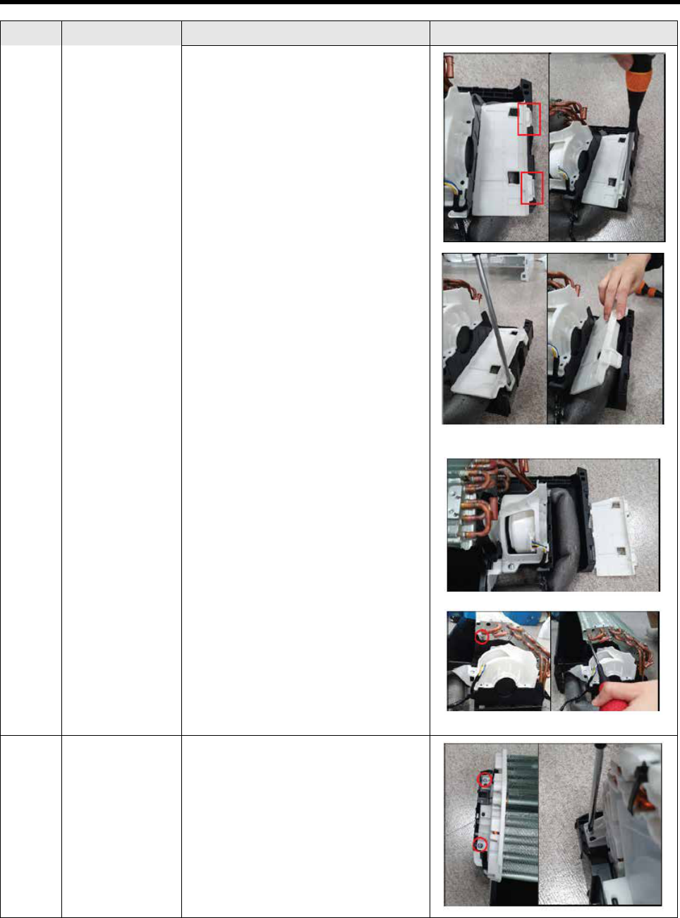
NO. Parts Procedure Remark
6) Please remove the screw 4ea
located on the rear panel.
(use + screwdriver)
7) Please separate the screw 2ea
located on the side panel.
(+ screw driver Use)
8) Please separate the screw 4ea
located on the side panel.
(+ screw driver Use)
9) Please remove the COVER
CONTROL OUT downward.

30
NO. Parts Procedure Remark
10) Please allign the wire such as
picture if you re-assemble after
separate connector w ir e .
If the connector is excessively
folded,thereisariskofre.
11) Please remove the CABINET
SIDE upward direction.
2
FAN & MOTOR 1) Please Loosen the NUT 1ea
clockwise.
(Using MONKEY SPANNER)
2) Please remove the HOUSING’s
MOTOR
WIRE.

31
NO. Parts Procedure
Remark
3)Removethexingpointsofthemo-
tor SCREW 2ea, please
disconnect the MOTOR turning coun-
terclockwise.
3 Capillary 1) Please remove the weld point in one
place. (COND-OUT)
If you remove the compressor and
heat exchanger, eliminate the refriger-
ant inside the compressor and heat
exchanger
completelywithweldingretoremove
the PIPE.
2) Please separate NUT SERVICE-
VALVE 2EA. (MONKEY SPANNER or +
SCREW DRIVER Use)
4 Condenser
(heat exchanger)
1) Please remove the welds in one
place.(COND-IN)

32
NO. Parts Procedure
Remark
2)Pleaseseparatethetwosidesxing
screws loose. (+ SCREW DRIVER Use)
5 Compressor
1) Please disassemble one NUT
counterclockwise
(using MONKEY SPANNER)
[OLP external compressor]
2) Disassemble COVER-
TERMINAL after remove the OLP.
BE CAUTION Engraved
position : C (black), S (white), R
(red)
[OLP internal compressor]
2) Please disassemble COVER-
TERMINAL.

33
NO. Parts Procedure
Remark
※howtodistinguishfromOLPinternal,
external compressor
: Check the compressor label
3) Please remove the compressor after
loosenthecompressorxedNUT3ea.
(Using MONKEY
SPANNER)
4) Please detach the two welds.
(SUCTION, DISCHARGE)

34
5-1 ASSY KIT CODE DB92-04845B ,F
Model ASSY KIT
AR09TXFYAWKNEU DB92-04845B
AR12TXFYAWKNEU DB92-04845B
AR09TXHZAWKNEU DB92-04845F
AR12TXHZAWKNEU DB92-04845F
5. ASSY CONTROL
No NAME CODE B F unit
1 CASE CONTROL-IN DB61-07432A 1 1 EA
2 PLATE CONTROL-LF DB61-07431A 1 1 EA
3 PLATE CONTROL-LOW DB61-07428A 1 1 EA
4 PLATE CONTROL-UP DB61-07429A 1 1 EA
5 PLATE CONTROL-SUB DB61-07427A 1 1 EA
6 HOLDER-WIRE DB61-05871A 1 1 EA
7 SCREW-TAPPING 6002-001163 1 1 EA
8 SCREW-TAPPING 6002-000213 2 2 EA
9 SCREW-SPECIAL 6009-001001 3 3 EA
10 CABLE TIE 6501-001075 1 1 EA
11 TERMINAL BLOCK_4P_GLOBAL DB37-00033A 1 1 EA
12 ASSY PCB DISPLAY_88 DB92-04833A 0 1 EA
ASSY PCB DISPLAY_88_WIFI DB92-04833B 1 0 EA
14 SENSOR TEMP DB32-00277A 1 1 EA
15 ASSY CONNECTOR WIRE-POWER DB93-17169A 1 1 EA
16 ASSY CONNECTOR WIRE-COMM DB93-17055B 1 1 EA
17 ASSY CONNECTOR WIRE-EARTH DB93-14245D 1 1 EA
19 ASSY CONNECTOR WIRE-FJM DB93-17178A 1 1 EA
20 ASSY PCB MAIN_DLX_GLOBAL DB92-04839A 1 1 EA
1
2
10
17
5
6
8
11
9
9
9
12
13
3
4
14
16
15
20
23

35
5-2 ASSY KIT CODE DB92-04842A
Model ASSY KIT
AR09TXFYAWKXEU
DB92-04842A
AR12TXFYAWKXEU
AR09TXHZAWKXEU
AR12TXHZAWKXEU
No NAME CODE Q’ty unit
1 ASSY-THERMAL GREASE 0205-000178 0.002 G
2 SCREW-MACHINE (TB) 6001-000722 2 EA
3 SCREW-TAPPING[N-V2MD]
(CLAMP)
6002-000231 2 EA
4 SCREW-TAPPING[N-V2MD]
(CASE)
6002-000239 2 EA
5 SCREW-TAPPING (PBA) 6002-000630 1 EA
6 SCREW-TAPPING (EARTH) 6009-001001 4 EA
7 ASSY-SCREW MACHINE (H/S) DB91-00933A 3 EA
8 HOLDER-WIRE CLAMP DB61-02200A 1 EA
9 RUBBER DB67-01534A 1 EA
10 PLATE CONTROL UP DB61-06600A 1 EA
11 PLATE CONTROL LOW DB61-06713A 1 EA
12 PLATE CONTROL DB61-06715D 1 EA
13 COVER CONTROL UP DB63-03378A 1 EA
14 CASE CONTROL LOW DB61-06714A 1 EA
15 SPRING DB81-00635A 2 EA
16 LABEL DB98-34030A 1 EA
17 HEAT SINK DB62-13007A 1 EA
18 TERMINAL BLOCK DB65-00274A 1 EA
19 TERMINAL BLOCK DB37-00036A 1 EA
20 ASSY CONNECTOR WIRE-
POWER
DB93-09495S 1 EA
22 ASSY CONNECTOR WIRE-
COMM
DB93-16402A 1 EA
23 ASSY CONNECTOR WIRE-
COMP
DB93-09497B 1 EA
24 ASSY CONNECTOR WIRE-AC
SIGNAL
DB93-17177A 1 EA
25 ASSY CONNECTOR WIRE-
EARTH
DB93-12121B 1 EA
26 ASSY CONNECTOR WIRE-
EARTH
DB93-12121B 1 EA
27 ASSY CONNECTOR WIRE-
REACTOR
DB93-17175B 1 EA
28 SENSOR TEMP DB95-05164A 1 EA
29 ASSY MODULE DB92-04837A 1 EA
1
17
2
3
4
5
6
9
8
10
11
12
15
16
18
19
28
30
29
23
24

36
6-1 INDOOR MAIN PCB CODE DB92-04839A
Parts Code Design Loc Parts Description Spec. Quantity Unit
0201-001528 COATING ADHESIVE-SIL LDC2577D,Y/GRN,175CPS 3.3 G
0201-001982 ADHESIVE-SIL ADHESIVE-SIL TSE3854DS-W,White,2.2,MIL-A-46146B,UL94V-0 0.0035 KG
0202-001463 SOLDER-WIRE SOLDER-WIRE LFC2-W3.0,D3,99.79Sn/0.2Cu/0.01P,No Flux 4.2 G
0202-001608
SOLDER-WIRE
FLUX
SOLDER-WIRE FLUX LFC7-107,D0.8,99.3Sn/0.7Cu/0.01P,Flux 3.5% 2.4 G
0204-005794 SOLVENT SOLVENT S-1000,(CH3)2CHOH,100%,0.79 1.2 G
0402-000324 BD100 DIODE-BRIDGE D3SB60,600V,4A,SIP-4,ST 1 PC
1203-002722 REG900 IC-POSI.FIXED REG.
KA78R15,TO-220,4P,10x15mm,PLASTIC,14.6/15.4V,1.
5W,-20to+80C,ST
1 PC
1203-009020 PW100 IC-PWM CONTROLLER
TOP253P,DIP,7P,6.35x9.57mm,PLASTIC,-
0.3/700V,15W,-40to+150C,1.37A,ST
1 PC
1404-001194 PTC320 THERMISTOR-PTC
39ohm(Typ),270VAC,1.2A,RADIAL(DISC),0.2A,11x5
mm,TP
1 PC
1404-001413 NTC100 THERMISTOR-NTC
18ohm,3A,3200K,19MWC,15mm,TP,17x6mm,RADIA
L(DISC)
1 PC
1405-000160 VA100 VARISTOR 680V,560VDC,4500A,17.5x8mm,TP,1120V,500pF,D14 1 PC
2201-002688 C104 C-CERAMIC,DISC 2.2nF,20%,400Vac,Y5U,TP,12.5x7mm,10mm 1 PC
2201-002688 C105 C-CERAMIC,DISC 2.2nF,20%,400Vac,Y5U,TP,12.5x7mm,10mm 1 PC
2201-002688 C112 C-CERAMIC,DISC 2.2nF,20%,400Vac,Y5U,TP,12.5x7mm,10mm 1 PC
2201-002688 C113 C-CERAMIC,DISC 2.2nF,20%,400Vac,Y5U,TP,12.5x7mm,10mm 1 PC
2301-002032 XC100 C-FILM,LEAD-PPF 100nF,10%,275Vac,TP,12.5x6x12mm 1 PC
2401-003139 CE104 C-AL 1000uF,20%,25V,WT,TP,10x20mm,5mm 1 PC
2401-004393 CE103 C-AL 100uF,20%,500V,BK,25.4x30mm,10mm 1 PC
3002-001129 BZ600 BUZZER-PIEZO 85dB,2KHz,BK 1 PC
3601-001336 F101 FUSE-AXIAL LEAD 250V,3.15A,TIME-LAG,CERAMIC,5.2x20mm 1 PC
3711-000260 CNP100 HEADER-BOARD TO CABLE 1WALL,3P,1R,7.92mm,STRAIGHT,SN,BLU 1 PC
3711-000296 CN900 HEADER-BOARD TO CABLE 1WALL,6P,1R,3.96MM,STRAIGHT,SN,WHT 1 PC
3711-000880 CN320 HEADER-BOARD TO CABLE BOX,3P,1R,2.5MM,STRAIGHT,SN,RED 1 PC
3711-002001 CN230 HEADER-BOARD TO CABLE
BOX,20P,2R,2.0mm,STRAIGHT,SN,BLK,5.0X22.0X6
.6mm
1 PC
3711-004122 CN340 HEADER-BOARD TO CABLE BOX,14P,1R,2mm,STRAIGHT,SN,WHT 1 PC
3711-004484 CN800 HEADER-BOARD TO CABLE BOX,5P,1R,2mm,STRAIGHT,SN,WHT 1 PC
3711-005096 CN801 HEADER-BOARD TO CABLE BOX,5P,1R,2MM,STRAIGHT,SN,BLK 1 PC
3711-005097 CN810 HEADER-BOARD TO CABLE BOX,5P,1R,2MM,STRAIGHT,SN,BLU 1 PC
3711-005098 CN390 HEADER-BOARD TO CABLE BOX,5P,1R,2MM,STRAIGHT,SN,RED 1 PC
3711-009520 CN100 HEADER-BOARD TO CABLE
BOX,28P,2R,2.0mm,STRAIGHT,SN,NTR,30x9.6x10.
6mm
1 PC
DB27-00063A FT100 COIL CHOKE 16mH,2.3A,13.0x10.0mm,Mn-Zn,4P,DIP 1 PC
DB27-00102A L320 COIL CHOKE 1.0mH,2.5A,8.4x3.4,Mn-Zn,4,DIP 1 PC
DB94-08038A ASSY PCB AUTO
MAIN,QMD RAC AR9500T,142x121mm,Y,220V-
240V,5V,12V,17V,10W,PF1-RAC,485 INV,DLX,DB92-
04839A
1 PC
2003-002212 R108 R-METAL OXIDE(S) 75Kohm,5%,2W,AF,TP,3.9x10mm 1 PC
2201-002709 C109 C-CERAMIC,DISC 0.033nF,5%,1000V,SL,TP,6.3x5mm,5mm 1 PC
2202-002252 C107 C-CERAMIC,MLC-RADIAL 1nF,10%,1000V,R,9.0x6.0x5.0mm 1 PC
2401-000480 CE900 C-AL 10uF,20%,50V,GP,TP,5x11mm,5mm 1 PC
2401-000481 CE108 C-AL 10uF,20%,50V,WT,TP,5x11mm,5mm 1 PC
2401-001573 CE107 C-AL 47uF,20%,50V,GP,TP,6.3x11mm,2.5mm 1 PC
2401-001573 CE123 C-AL 47uF,20%,50V,GP,TP,6.3x11mm,2.5mm 1 PC
6. Electrical Parts List

37
Parts Code Design Loc Parts Description Spec. Quantity Unit
2401-001573 CE902 C-AL 47uF,20%,50V,GP,TP,6.3x11mm,2.5mm 1 PC
2401-001838 CE105 C-AL 470uF,20%,25V,WT,TP,10x16mm,5mm 1 PC
2401-003607 CE106 C-AL 10uF,20%,50V,HR,TP,5x11mm,5mm 1 PC
DB94-08039A ASSY PCB SMD
MAIN,QMD RAC AR9500T,142x121mm,Y,220V-
240V,5V,12V,17V,10W,PF1-RAC,485 INV,DLX,DB92-
04839A
1 PC
DC26-00053A TRAN101 TRANS SWITCHING
AC85-265V,500mA,400mA,400mA,5V,12V,15V,S/W
TRANS,15W,EE2218
1 PC

38
6-2 ASSY PCB DISPLAY CODE DB92-04833B
Parts Code Design Loc Parts Description Spec. Quantity Unit
0201-001528 COATING ADHESIVE-SIL LDC2577D,Y/GRN,175CPS 0.9 G
DB61-07412A CASE-LED CASE-LED AR9500T, QMD RAC,HIPS,T1.8,L69,BLACK,8.8 1 PC
DB64-03476A
WINDOW
DISPLAY
WINDOW DISPLAY
AR9500T, QMD RAC,PET,T0.27,8.8 FILM, AI, Timer,
Wi-Fi
1 PC
DB94-08137A ASSY PCB SMD
DISPLAY_DLX,QMD RAC
AR9500T,84.5x50mm,N,WIFI,DB92-04833B
1 PC

39
7. Wiring Diagram
7-1 Indoor Unit
AR09TXFYAWKNEU
AR12TXFYAWKNEU
AR09TXHZAWKNEU
AR12TXHZAWKNEU
CODE : DB68-08680A-01

40
7-2 Outdoor Unit
AR09TXFYAWKXEU
AR12TXFYAWKXEU
AR09TXHZAWKXEU
AR12TXHZAWKXEU
CODE : DB68-08682A-01

41
8. PCB Diagram
8-1 INdoor Main PCB CODE DB92-04839A
DLX_QMD_Indoor Main PCB : DB92-04839A-E
CNP100
CN800
CN801
CN230
CN810
CN320
CN390
CN340
CN900
CN100
#1 : COM1_RXD
#2 : COM1_TXD
#3 : nTRST
#4 : TDO
#5 : TCK
#6 : TDI
#7 : TMS
#8 : TraceCLK
#9 : SGND
#10 : +5V
#11 : +5V
#12 : BOOT
#13 : MODEL NAME
#14 : Trace3
#15 : NULL
#16 : NULL
#17 : SGND
#18 : Trace2
#19 : Trace1
#20 : Trace0
#1 : 310V
#2 : NULL
#3 : GND
#4 : +15V
#5 : V_DET ECT_OV_OUT
#6 : P_GND
#22 : NULL
#23 : +12V
#24 : NULL
#12 : SGND
#14 : EVA_IN_TEMP
#15 : ADDRESS_SW
#16 : SGND
#17 : MAIN_RX-WIFI_TX
#14 : COM2_MICOM_AD
CN100 : DISPLAY
#1 : LED_DIO
#2 : +5V
#3 : LED_CLK
#4 : SGND
#10 : +12V
#11 : COM2_PCTRL_MICOM
#12 : COM2_VCHECK_A
#13 : COM2_VCHECK_B
#4 : COM2_ENABLE
#5 : EXT_CTRL
#6 : COMP_CHK_OUT
#7 : ERROR_CHK_OUT
#8 : COM2_VCC_PS_OUT
CN230 : DOWNLOAD
#4 : SGND
#5 : +12V
#13 : REMOCON_INT
#8 : HUM_SENSOR
#9 : SGND
#10 : +5V
#11 : +5V
#5 : O7
#18 : EVA_OUT_TEMP
#25 : MDS_2
#26 : NULL
#27 : MDS_1
#28 : +5V
#19 : MAIN_TX-WIFI_RX
#20 : SGND
#21 : WIFI_CONTROL
#2 : NULL
#2 : O1
#3 : OPT ION
#3 : O2
CN320 : COMM
#1 : PTC320
#4 : O3
#5 : O4
#3 : NE_00
#2 : COM2_Rx
#2 : MAIN_TX-WIFI_RX
#5 : EARTH
#3 : COM2_INVERSE
#3 : WIFI_CONTROL
#1 : L
#1 : MAIN_RX-WIFI_TX
CN800 : STEP UP/DOWN
#5 : O7
CN900 : FAN MOTOR
#3 : O5
#3 : O5
#4 : O6
#4 : O6
#1 : +12V
CNP100 : POWER
CN340 : WIRED REMOCON
CN390 : WIFI
#1 : COM2_Tx
#9 : SGND
CN810 : STEP LEFT/RIGHT
#1 : +12V
#5 : LED_RST
#6 : H_ROOM_TEMP
#7 : POWER_SW
#1 : +12V
#2 : O4
#2 : O4
CN800 : STEP UP/DOWN
42
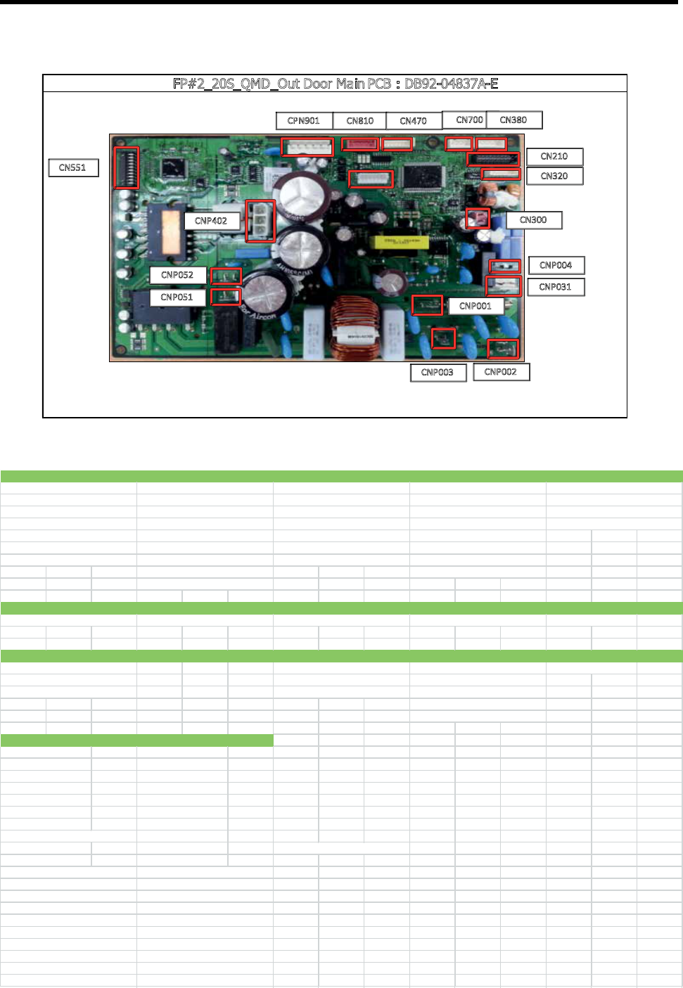
8-2 Outdoor Main PCB CODE DB92-04837A-E
FP#2_20S_QMD_Out Door Main PCB : DB92-04837A-E
CPN901
CN810
CN470
CN700
CN380
CN210
CN320
CN300
CNP004
CNP031
CNP001
CNP003
CNP002
CN551
CNP402
CNP052
CNP051
CNP003 : EARTH
#1 : EARTH
CN300 : INDOOR-OUTD
OOR
CNP004 : EARTH
#1 : F1 #1 : EARTH
#2 : F2
CN201 : DOWNLOAD & JT
AG
CN551 : INV-DOWNLOAD
#1 : RXD_INV #1 : RXD_INV
#2 : TXD_INV #2 : TXD_INV
#3 : BOOT_MAIN #3 : BOOT_INV
#4 : TDO_MAIN#4 : TDO_INV
#5 : TCK_MAIN#5 : TCK_INV
#6 : TDI_MAIN#6 : TDI_INV
#7 : TMS_MAIN#7 : TMS_INV
#8 : TRACECLK_MAIN #8 : nTRST _INV
#9 : SGND #9 : P_GND1
#10 : +5V_1#10 : +5V
#1 : REACTOR
CNP001 : L
#1 : L
CNP002 : N
#1 : N
#6 : SGND
#7 : +12V_1
#5 : +5V_1
CNP031 : 4WAY
#1 : LI_S
#2 : NULL
#3 : RY031
#1 : DRED1
#2 : DRED1
#3 : DRED1
#4 : SGND
#2 : V
#3 : U
#1 : W
#7 : OLP_TH
CNP052 : REACTOR
#4 : TXD_SOLUTION
#5 : +5V_1
CN380 : DREDCNP402 : COMP
CNP051 : REACTOR
#1 : REACTOR
#8 : SGND
#6 : FAN_FG
#6 : SGND
#20 : TRACE0_MAIN
#20 : DA_DAT A
#18 : TRACE2_MAIN
#18 : DA_CLK
#19 : TRACE1_MAIN
#19 : DA_CS
#16 : NULL
#16 : NULL
#17 : SGND
#17 : P_GND1
#14 : TRACE3_MAIN
#14 : NULL
#15 : NULL
#15 : NULL
#12 : NULL
#12 : NULL
#13 : NULL
#13 : NULL
#11 : +5V_1
#11 : +5V
#4 : +15V
#4 : O1
#4 : SGND
#4 : HEATER_L
#5 : FAN_PWM
#5 : +12V_1
#5 : COND_TH
#2 : ENABLE_SOLUTION
#2 : NULL
#2 : O3
#2 : SGND
#2 : SGND
#3 : INVERSE_SOLUTION
#3 : P_GND1
#3 : O2
#3 : DIS_TH
#3 : HEATER_N
CN700 : HEATER
#1 : +5V_1
#1 : DC_LINK
#1 : O4
#1 : OUT_TH
#1 : +12V_1
CN320 : SUB CPN901 : BLDC FAN CN810 : EEV-A CN470 : SENSOR

43
8-3 DISPLAY PCB DB92-04833B

44
8-4 Wire connecting the indoor unit terminal blocks
1. Terminal press of Ring terminal shall be set facing up before connecting wire.
2. There shall be no empty space between Ring terminal and Screw after Clamp.
If not, there exists a possibility of fire which can be caused by electric heat in the connecting part.

45
9-1 Name of Each Part
9-1-1 Indoor Unit
The design and shape are subject to change according to the model.
u
Main Parts
01
02
03
04
05
06
08
07
01 Air intake
02 Airlter
03 Front panel
04 Airowblade(upanddown)
05Airowblade(leftandright)
06 Power button/Remote control receiver
07 Room temperature sensor
08 Display
9. Operating Instructions

46
u
Display
01 Temperature indicator
Filter reset indicator ( )
Auto clean indicator ( )
02 Timer indicator
good'sleep indicator
03 Eco indicator
01
02 03 04
01 Temperature indicator (numeric)
Filter reset indicator ( )
Electricity consumption indicator (numeric)
Auto clean indicator ( )
02 AI Auto indicator
03 Timer indicator
good’sleep indicator
04 Wi-Fi indicator
AR**TYHY***
AR**TYFY***

47
9-2 Wireless Remote control-Buttons and Display
DB96-24901F
08
09
10
07
01
05
06
16
17
18
20
21
02
03
04
11
12
13
19
14
15
01 Set temperature indicator
02 Timer option indicator
03 Operation mode indicator
04 Options indicator
05 Low battery indicator
06 Transmit indicator
07 Fan speed indicator
08 Wind-Free indicator
09 Vertical air swing indicator
10 Horizontal air swing indicator
11 Power button
12 Temperature button
13 Timer button
14 Fan speed button
15 Direction button/Selection button
16 Vertical air swing button
17 Mode button
18 Fast/Eco button
19 Horizontal air swing button
20 Options/Clean button
21 SETbutton/Temperaturetypebutton(℃
↔
℉)

48
10-1 Items to be checked rst
1
The input voltage should be rating voltage ±10% range.The air conditioner may not operate properly if the
voltage is out of this range.
2 Is the line cable linking the indoor unit and the outdoor unit linked properly? The indoor unit and the outdoor
unit shall be linked by 5 cables. Check the terminals if the indoor unit and outdoor unit are properly linked by the
same number of cables. Otherwise the air conditioner may not operate properly.
3 When a problem occurs due to the contents illustrated in the table below it is a symptom not related to the
malfunction of the air conditioner.
NO. Operation of air conditioner Explanation
1
The OPERATION indication LED(BLUE) blinks when a
powerplugoftheindoorunitispluggedinforrst
time.
It indicates power is on. The LED stops blinking if
the operation ON/OFF button on the remote control
unit is pushed.
2
In a COOL operation mode, the compressor does not
operate at a room temperature higher than the
setting temperature that the INDOOR FAN should
operate.
[ In case of heat pump model ]
In a HEAT operation mode, the compressor does not
operate at a room temperature lower than the
setting temperature that indoor fan should operate.
In happens after a delay of 3 minutes when the
compressor is reoperated. The same phenomenon
occurs when a power is on. As a phenomenon that
the compressor is reoperated after a delay of 3
minutes, the indoor fan is adjusted automatically
with reference to a temperature of the air blew.
3
Fan speed setting is not allowed in DRY mode. The speed of the indoor fan is set to LL in DRY mode.
Fan speed is selected automatically in AUTO mode.
4
Compressor stops operation intermittently in Dry
mode.
Compressor operation is controlled automatically in
DRY mode depending on the room temperature and
humidity.
5
Timer LED(ORANGE) of the indoor unit lights up and
the air conditioner does not operate.
Timer is being activated and the unit is in ready
mode. The unit operates normally if the timer
operation is cancelled.
6
The compressor stops intermittently in a COOL
mode or DRY mode, and fan speed of the indoor unit
decreases.
The compressor stops intermittently or the fan
speed of the indoor unit decreases to prevent inside/
outside air frozen depending on the inside/outside
air temperature.
7
[In case of heat pump model]
Compressor of the outdoor unit is operating al-
though it is turned off in a HEAT mode.
When the unit is turned off while de-ice is activated,
the compressor continus operation for up to 9
minutes(maximum) until the deice is completed.
8
[In case of heat pump model]
The compressor and indoor fan stop intermittenly in
HEAT mode.
The compressor and indoor fan stop intermittently if
room temperature exceeds a setting temperature in
order to protect the compressor from overheated air
in a HEAT mode.
9
[In case of heat pump model]
Indoor fan and outdoor fan stop operation
intermittently in a HEAT mode.
The compressor operates in a reverse cycle to
remove exterior ice in a HEAT mode, and indoor fan
and outdoor fan do not operate intermittently for
within 20% of the total heater operation.
10. Troubleshooting

49
10-2 Communication Error
10-2-1 Communication Error
Indoor display
7-SEG DISPLAY DESCRIPTION
C101/C102 Communication error(Indoor<->outdoor)
Outdoor display
1min. Time out Comm.
Abnormal Communication
LED ON LED BLINKING
LED OFF
1. Checklist :
1) Is the cable between the indoor unit and outdoor unit connected correctly?
2) Isn’t the power cable and communication cable cross?
2. Troubleshooting procedure
YES
NO
NO
NO
NO
YES
YES
YES
YES
Restart after power off .
Is the communciation error occurred again?
Is the connection of power cable and
communication cable normal?
Is the power is normal?
(check the LED Lamp)
Exchange the indoor unit PBA.
Is the communication error occurred again?
Exchange the outdoor unit PBA.
Terminate the service.
Exchange the PBA of no power unit.
Correct the wrong cable.
Terminate the service.

50
10-2-2 Indoor temperature sensor Error
Indoor display
7-SEG DISPLAY DESCRIPTION
C121 Indoor room temp sensor error
LED ON LED BLINKING
LED OFF
1. Checklist :
1) Is the indoor units temperature sensor connected correctly?
2) Is the sensor placed correctly?
3) Does the both terminal of sensor satisfy the resistance value in accordance with temperature?
2. Troubleshooting procedure
YES
YES
NO
NO
YES
Detach the assembled sensor from the PBA
sensor connector and measure the sensor
resistance with ohmmeter(tester)
Assy Sensor Replace
Sensor resistance value : 20°C- 12.09 kohm
30°C - 8.31 kohm
35°C - 6.94 kohm
40°C- 5.83 kohm
Is the sensor resistance value
10kohm±3% at the room temperature
of 25°C ?
Connect the sensor to PBA connector (6pin)
supplypowerandmeasurethevoltageof#1-#2
in the connector
Below 0.5V or Over 4.5V?
Micom error or connector check
Exchange the indoor PBA
Exchange the indoor PBA

51
10-2-3 Indoor fan motor speed detecting error (BLDC fan)
Indoor display
7-SEG DISPLAY DESCRIPTION
C154 Indoor fan error
LED ON LED BLINKING
LED OFF
1. Checklist :
1) Is the indoor units fan motor properly connected with the connector(CN72)?
2) Is the AC voltage correct?
2. Troubleshooting procedure
NO
YES
YES
YES
NO
YES
YES
NO
NO
NO
Restart after power off.
Does the fan rotate?
Power o and Separate the Fan motor wire
from CN72 on Indoor PBA
Is there short among
eachpin#1~#6?
Reassemble the fan wire and input the power again
Is the fan error appeared again?
Terminate the
service
Exchange the Fan
motor
Follow the check procedure of Indoor unit
power supply error check
Exchange the Indoor PBA
IsthevoltageofCN72#1-#3over250Vdc?
Is the voltage of CN72
#3-#5and#3-#6within1Vdc~15Vdcduring
the operation?
PBA problem or Motor problem
ChangethePBArstandchecktheoperation
Exchange the Fan motor

52
10-2-4 Outdoor temperature sensor error
Indoor display
7-SEG DISPLAY DESCRIPTION
C221 Outdoor temperature sensor error
Outdoor display
Outdoor temperature sensor error
LED ON LED BLINKING
LED OFF
1. Checklist :
1) Is the sensor connected correctly?
2) Is the sensor placed correctly?
3) Does the both terminal of sensor satisfy the resistance value in accordance with temperature?
4) Is the resistance value of sensor connection pull-up correct?
2. Troubleshooting procedure
Model “A” “B”
ALL CN251 CN251#1-#2
YES
YES
NO
NO
NO
YES
YES
Is the sensor connector(“A”) connected
correctly in accordance with a color?
Is the sensor resistance value
“B” 10kohm±3% at the room temperature
of 25
℃?
Reconnect the sensor connector.
Sensor Replace
Sensor resistance value : 20 - 12.09 kohm
30 - 8.31 kohm
35 - 6.94 kohm
40 - 5.83 kohm
Exchange the Outdoor PBA
Connect the sensor to PBA connector supply
power and measure the voltage of "B"in the
connector
Below 0.5Vdc or Over 4.5Vdc?
Micom error or connector check
Exchange the Outdoor PBA

53
10-2-5 Outdoor Cond temperature sensor error
Indoor display
7-SEG DISPLAY DESCRIPTION
C231 Outdoor Cond temperature sensor error
Outdoor display
Outdoor Cond temperature sensor error
LED ON LED BLINKING
LED OFF
1. Checklist :
1) Is the sensor connected correctly?
2) Is the sensor placed correctly?
3) Does the both terminal of sensor satisfy the resistance value in accordance with temperature?
4) Is the resistance value of sensor connection pull-up correct?
2. Troubleshooting procedure
Model “A” “B”
ALL CN251 CN251#5-#6
YES
YES
NO
NO
NO
YES
YES
Is the sensor connector("A")
connected correctly in accordance
with a color?
Is the sensor resistance value
"B" 10kohm±3% at the room temperature
of 25
℃?
Connect the sensor to PBA connector
supply
power and measure the voltage of “B”
communication cable
Reconnect the sensor connector.
Sensor Replace
Sensor resistance value : 20 - 12.09kohm
30 - 8.31kohm
35 - 6.94kohm
40 - 5.83kohm
Exchange the Outdoor PBA
Below 0.5Vdc or Over 4.5Vdc?
Micom error or connector check
Exchange the Outdoor PBA

54
10-2-6 Outdoor Discharge temperature sensor error
Indoor display
7-SEG DISPLAY DESCRIPTION
C251 Outdoor Discharge temperature sensor error
Outdoor display
Outdoor Discharge temperature sensor error
LED ON LED BLINKING
LED OFF
1. Checklist :
1) Is the sensor connected correctly?
2) Is the sensor placed correctly?
3) Does the both terminal of sensor satisfy the resistance value in accordance with temperature?
4) Is the resistance value of sensor connection pull-up correct?
2. Troubleshooting procedure
Model “A” “B”
ALL CN251 CN251#1-#2
YES
YES
NO
NO
NO
YES
YES
Is the sensor connector(“A”) connected
correctly in accordance with a color?
Is the sensor resistance value
“B” 200kohm±3% at the room temperature
of 25
℃?
Reconnect the sensor connector.
Sensor Replace
Sensor resistance value : 20 - 242kohm
30 - 166ohm
35 - 138ohm
40 - 115kohm
Exchange the Outdoor PBA
Connect the sensor to PBA connector supply
power and measure the voltage of "B"in the
connector
Below 0.5Vdc or Over 4.5Vdc?
Micom error or connector check
Exchange the Outdoor PBA

55
10-2-7 Operation condition secession error
Indoor display
7-SEG DISPLAY DESCRIPTION
C440
Prohibit Operation Condition Error (Heating)
C441
Prohibit Operation Condition Error (Cooling)
Outdoor display
Operation condition secession
LED ON LED BLINKING
LED OFF
1. Checklist :
1) Check the temperature around the outdoor unit.
2. Troubleshooting procedure
NO
YES
YES
Restart after power off
Terminate the service
Is the operation condition secession
error appeared again?
*Heatingmode*
Is the outdoor temperature over 40
℃ or
under -30 ℃?
*Coolingmode*
Is the outdoor temperature under -7
℃?
The temperature condition is too poor to
operate. Wait until temperature is changed

56
10-2-8 EEPROM error / OTP error
Indoor display
7-SEG DISPLAY DESCRIPTION
C470 EEPROM Data Error (no data)
C471
OTP errorEEPROM Data Error
(Main Micom Inv Micom)
Outdoor display
EEPROM Data Error (no data)
OTP errorEEPROM Data Error (Main MicomInv Micom)
LED ON LED BLINKING
LED OFF
1. Checklist :
1) Is there a short around micom?
2) Is there a short around “A”?
3) Did you download or insert EEPROM IC, after changing outdoor PBA?
2. Troubleshooting procedure
NO
YES
power off and download EEPROM data
(or. Insert the service EEPROM IC)
Restart after power off
Is the error appeared again?
Exchange the Outdoor PBA
Terminate the service

57
10-2-9 Outdoor Fan motor error
Indoor display
7-SEG DISPLAY DESCRIPTION
C458 Outdoor fan error
Outdoor display
Outdoor fan error
LED ON LED BLINKING
LED OFF
1. Checklist :
1) Are the input power voltage and the power connection correct?
2) Is the motor wire connected to the outdoor PBA correctly?
3) Is there no assembly error or non-assembly in the terminal of motor wire connector?
4) Is there no obstacle at the surrounding of motor and propeller?
2. Troubleshooting procedure
NO
YES
YES
YES
NO
YES
YES
NO
NO
NO
Restart after power off.
Does the fan rotate?
Is the fan error appeared again?
Isthevoltageof"A"#1-#3over250Vdc
Isthevoltageof"A"#3-#5and
#3-#6within1Vdc~15Vdcduring
the operation?
Reassemble the fan wire and input the power again
PBA problem or Motor problem
ChangethePBArstandchecktheoperation
Exchange the Fan motor
Exchange the Outdoor PBA
Follow the check procedure of outdoor
unit power supply error check
Terminate the
service
Exchange the
Fan motor
Is there short among
eachpin#1~#6?
Power off and Separate the Fan motor wire
from "A" on Outdoor PBA

58
10-2-10 Compressor starting error
Indoor display
7-SEG DISPLAY DESCRIPTION
C461 Comp starting error
Outdoor display
Comp starting error
LED ON LED BLINKING
LED OFF
1. Checklist :
1) Is the connection of cable for the compressor?
2) Is the compressor wire is connected clockwise? U(RED)-V(BLU)-W(YEL)
3) Is the interphase resistance of compressor normal?
2. Troubleshooting procedure
NO
NO
NO
NO
YES
YES
YES
YES
Restart after power off.
Is the restart error occurred again?
Download the EEPROM data
Is the restart error occurred again?
Is the compressor body and interphase
resistance insulated?
Exchange the compressor
Exchange the Outdoor PBA
Terminate the service
Connect the comp wire normally
Terminate the service
Is the connection of compressor wire is normal?

59
10-2-11 Compressor wire missing error/rotation error
Indoor display
7-SEG DISPLAY DESCRIPTION
C467 Compressor wire missing errorr/rotation error
Outdoor display
Compressor wire missing error/rotation error
LED ON LED BLINKING
LED OFF
1. Checklist :
1) Is the connection of cable for the compressor?
2) Is the compressor wire is connected clockwise? U(RED)-V(BLU)-W(YEL)
3) Is the interphase resistance of compressor normal?
2. Troubleshooting procedure
NO
NO
NO
NO
YES
YES
YES
YES
Restart after power off.
Is the restart error occurred again?
Is the connection of
compressor wire is normal?
(PBA and Compressor)
Is the restart error occurred again?
Is the compressor body and
interphase resistance insulated?
Exchange the compressor
Exchange the Outdoor PBA
Terminate the service
Connect the comp wire normally
Terminate the service

60
10-2-12 Current sensor error/Input current sensor error
Indoor display
7-SEG DISPLAY DESCRIPTION
C462 AC Input I_Limit Trip Error
Outdoor display
Current sensor error
Input current sensor error
LED ON LED BLINKING
LED OFF
1. Checklist :
1) Is the PFC Shunt(“A”) resistance value correct? Check the resistor is opened
2) Is the IPM Shunt(“B”) resistance value correct? Check the resistor is opened
3) Is there no short or open around “C”?
2. Troubleshooting procedure
NO
NO
YES
YES
Restart after power off.
Is the PFC shunt and IPM
shunt resistance value correct?
Is the current sensor error appeared again?
Exchange the Outdoor PBA
Exchange the Outdoor PBA
Terminate the service

61
10-2-13 O.C(Over Current) error
Indoor display
7-SEG DISPLAY DESCRIPTION
C464 IPM Over Current(O.C) Error
Outdoor display
Current sensor error
LED ON LED BLINKING
LED OFF
1. Checklist :
1) Is the IPM Shunt resistance value correct? Check the resistor is opened
2) Is the condition of surrounding temperature abnormal overload?
3) Is there any problem as like the temperature sensor separation or measurement value error?
4) Is the interphase resistance of compressor normal?
2. Troubleshooting procedure
NO
NO
NO
NO
YES
YES
YES
YES
Restart after power off.
Is the O.C error occurred?
Is the connection of compressor wire is normal?
Is the O.C error occurred again?
Is the condition of indoor/outdoor
temperature normal load?
Terminate the service
Connect the comp wire normally
Terminate the service
Restart after returning to the normal load
Is the O.C error
occurred again?
Terminate the service

62
NO
NO
YES
Is the position of
temperature sensor and sensing
value normal?
Correct the sensor position or
exchange the sensor
Exchange the Outdoor PBA
Exchange the compressor
Is the compressor body
and interphase resistance
insulated?

63
10-2-14 No power outdoor (Initial Diagnosis) (Not displayed)
1. Checklist :
1) Is input power normal?
2) Is AC power linked correctly? (L,N,E)
3) Is mis-wiring between communication wire and Power wire?
4) Is mis-wiring between Main PBA and SMPS PBA wire?
5) Is input voltage of SMPS AC in Main PBA (CN150) normal?
6) Is the voltage of SMPS DC in Main PBA (CN151,CN152) normal?
2. Troubleshooting procedure
NO
NO
NO
NO
.
YES
YES
YES
YES
Unplug the power cord
Check the fuse open or not? (F001)
Restart after power off.
Is the power normal?
Is AC power is normal for SMPS?
CN150:220Vac~240Vac
Check SMPS wire connection
Exchange the Main PBA
Check the power source.
Exchange the Main PBA
Reconnect the power wire correctly.
Is the power cable from
terminal block to PBA is correct?
L :CN002, N:CN001, EARTH:CN003

64
10-2-15
When the Up/Down, Left/Right, Grill louver motor does not operate (Initial Diagnosis)
(Not displayed)
1. Checklist :
1) Is the input power voltage normal?
2) Is the Up/Down louver motor properly connected with the connector? (CN61, CN62, CN63)
2. Troubleshooting procedure
NO
YES
YES
NO
NO
NO
YES
YES
Unplug the power cord and plug it after
30seconds later.
Is the lamp blinking?
Is the connected louver wire?
Does operation start when swing button of the
remote control unit pushed?
Isthevoltagechangeableatthepin#2~#5of
CN61,CN62, CN63
(louver connector)?
Up/Down louver motor is faulty.
Exchange the PBA
Normal
Connect the wire PBA to louver motor
Check the as in the procedure.
No power.

65
10-2-16 When the remote control is not receiving
1. Checklist :
1) Check if the connector was normally assembled.
2) Check the battery in remote control
3) All the lights out and check again : Change electronic typed to a rescent light
4) Put the set in operation and check the voltage of display PBA
5) Replace the display PBA
2. Troubleshooting procedure
NO
NO
NO
YES
YES
YES
NO
If the connector was normally assemble?
Have the battery in remote control?
Insert the battery in remote control.
All the lights out ?
Changeelectronictypeduorescentlight.
Re-check the connector
Exchange the display PBA
Check the connector to normally assemble.

66
10-2-17 Smart Install error
1. Checklist :
1) Check the leakage region.(Use leakage detection liquid or soapy water)
2) When leakage region is found from service valve and piping connection re nut part : After the related
measures to check the refrigerant supplements and operation.
3) If the leakage region is pipe welding part : Weld leakage region after refrigerant gas release.(Brass parts
should only apply)
4) If the leakage region is surface area (Heat exchanger or pipe welding region is not) : Replace parts.
5) Check the PBA Relay
- Display of indoor unit : Ensure that the operating pilot lamp has been lighted.
- Ensure that the Relay input voltage of indoor unit PBA is normally.(If the PBA is defective, replace)
2. When the air conditioner is in standby status, use the remote controller to start the Smart Install mode.
1) Press the [SET], [Mode], [Power] button simultaneously for 4 seconds.
-Smart Install mode can be operated only with the supplied remote controller.
-During the Smart install mode procedure, remote controller cannot be operated.
3. Troubleshooting procedure
NO
NO
NO
YES
YES
YES
YES
YES
YES
YES
Did stop valve of
the low pressure valve open
perfectly?
Open perfectly stop valve.
(Use the 4mm hex wrench)
Re-connect after 3 seconds, after separate the power
cord. And then begin cooling operation with minimum
temperature that can establish. (use the remote control)
Among compressor operation, does cold air
come out from the indoor unit?
End
Execute the related
troubleshooting.
- Discharge temperature and the indoor
temperature measurements conrm
that the difference is more than 10
°C
- Fill up perfectly refrigerant after
re-vacuum.
[Execute the troubleshooting]
Check the refrigerant leaks.
Check the PCB Relay.
Does measurement
pressure include in ±10% extent
of reference pressure?
Connect the manifold gauge to the service
port of low pressure side service valve and
then measure the refrigerant pressure.

67
10-2-18 Outdoor OLP over temperature error (One way Inverter Only)
Indoor display
DESCRIPTION
No display about the outdoor condition
Outdoor display
C463
IPM Over Current(O.C) Error
LED ON LED BLINKING
LED OFF
1. Checklist :
1) Is the sensor placed correctly?
2) Check the service valve is closed
3) Check the compressor locking or gas leak
2. Troubleshooting procedure
YES
NO
NO
YES
NO
YES
YES
NO
Restart after power off.
after10min~1Hr
Is the OLP over temperature sensor
error appeared again?
Check the OLP Sensor postion on the
Compressor Top
Is the OLP over temperature sensor
error appeared again?
Check the service valve is closed
Check the compressor locking or gas leak
Is the OLP over temperature sensor
error appeared again?
The condition is too poor for air conditioner to operate
Wait until OLP temperature is decreased Restart after
power off
Exchange the Outdoor PBA
Exchanged the Compressor
Terminate the service
Terminate the service
Terminate the service

68
11-1 Indoor unit
11. Block Diagram

69
11-2 Outdoor unit

70
11-2-1 Pre-inspection Notices
1
Check if you pulled out the AC power plug when you eliminate the PCB or front panel.
2 Don’t hold the PCB side not impose excessive force on it to eliminate the PCB.
3 Don’t pull the lead wire but hold the whole housing to connect or disconnect a connector to the PCB.
4 IncaseofoutdoorPCBdisassembly,checkrstthecompletedischargeofcondenserafter1minute
power off.
11-2-2 Inspection procedure
1
Check connector connection and peeling of PCB or bronze coating pattern when you think the PCB is
broken.
2 The PCB is composed of 3 parts.
• Indoor Main part : MICOM and surrounding circuit, relay, fan motor sensing and driving circuit,
temperature sensing circuit power circuit of SMPS, buzzer circuit. Communication circuit.
• Display part : LED lamp, Switch, Remote-control module.
• Outdoor Main part : MICOM and surround circuit, fan motor sensing and driving circuit, compressor
driving circuit power circuit of SMPS, PFC control circuit, 4way circuit, communication circuit, OPTION
(EEV control circuit, temperature sensing circuit).
11-2-3 Indoor detailed inspection procedure
No.
Procedure Inspection Method Cause
1
Plug out and pull the PCB
out of the control box
Check the PCB fuse
1) Is 1st fuse disconnected?
2) Is 2nd fuse disconnected?
• Over current
• Indoor Fan motor short
• AC part and pattern short
of Indoor PBA
2
Supply power
If the operating lamp
twinkles
at this time , the above
1)~3)havenorelation
Check the power voltage
1) Is the BD71 input voltage
200Vac~240Vac?
• Power cord is fault, Fuse
open, Wrong Power cable
Wiring, AC part is faulty
2) Is the voltage between both
terminalofIC02pin#1-#212Vdc?
• Switching Trans of Power
circuit is faulty
3) Is the voltage between both
terminalofIC02pin#2-#35Vdc?
• Power circuit is faulty, Load
short
3
Press the ON/OFF button
1. Fan speed(high)
2. Continuous Operation
1) Is the voltage over AC 180V being
imposedonterminal#3-#5offan
motor connector (CN72)?
• Fan motor of the indoor is
faulty
2) The fan motor of the indoor unit
doesn’t run
• Fan motor connector(CN72)
is faulty
3) The power voltage between
terminal#3-#5ofthe
connector(CN72) is 0V
• PBA is faulty

71
11-2-4 Outdoor detailed inspection procedure
No.
Procedure Inspection Method Cause
1
Plug out and pull the PCB
out of the control box. Check
the PCB fuse (Wait 3 minutes
after power off)
1) Is 1st fuse disconnected? • Over current
• AC part and pattern short
of Outdoor PBA
2 Check the Wiring
1) Is the Compressor wire connected
clockwise?
2) Is the Reactor wire connected normal?
3) Is the Fan wire connected normal?
4) Is the 4way wire connected normal?
5) Is the sensor wire connected normal?
6) Is the EEV wire connected normal?
• Wrong assembly
• Installation(service)
condition is bad
3
“Supply power and operate
the set (Use Remote-con-
trol, button in indoor set)”
Check the power voltage
1) Is the voltage between Terminal
block L-N
200Vac~240Vac?
• Power cord is faulty, Wrong
Power cable Wiring
2) Is the C006 voltage
200Vac~240Vac?
• Fuse open
• .L,N,F1,F2 wire wrong wiring
(Terminal Block-PBA)
3) Is the CN150 voltage
200Vac~240Vac?
• Power circuit is faulty
• Load short
4)IsthePFC050(#26-#27)voltage
200Vac~240Vacafter3minutes
later?
• Fuse open
• L,N,F1,F2 wire wrong wiring
(Terminal Block-PBA)
• .PTC020 open
• .RY021, RY022 is faulty
• Outdoor Micom(IC201) error
5) Is the CE101 voltage
280Vdc~320dcafter3minutes
later?
• PFC050 is faulty
• Reactor wire is wrong
connection
• Power circuit is faulty, Load
short
• BLDC Fan motor error
6)IsthevoltageCN151#1-#2
voltage 15Vdc?
• Switching Trans of Power
circuit is faulty
• Load short
7)IsthevoltageCN152#1-#2
voltage 12Vdc?
• Switching Trans of Power
circuit is faulty
• Load short
8)IsthevoltageCN151#3-#2
voltage 5Vdc?
• Switching Trans of Power
circuit is faulty
• Load short
4
Check the LED lamp
display
1) Normal : RED on, GRN blink,
YEL off
2) Abnormal
- All o check no power
- abnormal display : check error
mode
• F1,F2 wire wrong wiring
• Outdoor PBA is faulty

72
12-1 Low Refrigerant Pressure Distribution
Note : Please measure the refrigerant pressure after the air conditioner operates on testing
cooling mode during more than 10 minutes.
■Indoor Temp. Variation :20°C~32°C
■Outdoor Temp. Variation : -5°C~45°C
12-2 Pressure & Capacity mark
■ Power/Heat
W cal/s kcal/h Btu/h HP kg.m/s Ib.m/s
1 0.23885 0.85985 3.4121 0.001341 0.10197 0.73756
4.1868 1 3.6 14.286 0.0056146 0.42693 3.088
1.163 0.27778 1 3.9683 0.0015596 0.11859 0.85778
0.29307 0.06999 0.252 1 3.9302x10
-4
0.029885 0.21616
745.7 178.11 641.19 2,544.4 1 76.04 550
9.8067 2.3423 8.4322 33.462 0.013151 1 7.233
1.3558 0.32383 1.0658 4.6262 0.0018182 0.13826 1
12. Reference Sheet

73
12-3 Q & A for Non-trouble
Classication Class Description
Cooling Q The cooling is weak.
A When it is hot outside, its cooling capacity decreases due to the increase of the ambient tem-
perature.Whenthedustltergetsblockedorwarmoutsideairgetsin,thecoolingcapacity
willdecrease.So,makesuretocleanthedustlterfrequently,preventheatlossbyclosing
the doors and insulate the cooling area by using curtains, blinds, shades or window tinting.
Q The cooling is good generally. But, it gets weak when it is considerably hot.
A It occurs when the outdoor unit is exposed to direct sun light and heat-up air is not ventilated
well. So,set up a sunblind over the outdoor unit and keep stu away from the unit to increase
the ventilation. When the cooling capacity decreases during a heat wave, clean the heat
exchanger of the outdoor unit or spray some cold water to the heat exchanger to increase the
cooling capability.
Q The cooling is weak. Does it need refrigerant charging?
A It is not correct charging refrigerant regularly. Except that you have moved in several times or
the connection pipes are broken, the refrigerant does not run low. So, when refrigerant is ad-
ditionally charged, it could be costly and cause a product’s failure. When the refrigerant leaks,
all of it will escape in a short time resulting in cooling failure and no water coming out of the
drain hose. So, if water comes out from the drain hose, it indicates the normal operation of
the product and it does not need refrigerant charging.
Q It fails to do cooling.
A When the air conditioner is set to ventilation or the desired temperature is set higher than
the current temperature, it fails to do cooling. In this case, select cooling or set the desired
temperature lower.
Leakage Q It oods the oor.
A Place the drain hose properly. When it is not placed properly, the drain water would ow back
ooding the oor. So, straighten out the drain hose for the water to be drained well.
Q Water drips at the drain connection (service valve) of the outdoor unit.
A When a glass bottle is taken out of the refrigerator, moisture gets condensed on its surface
due to the temperature dierences. The same principle applies to the air conditioner. When
cold refrigerant goes through the copper tube, moisture gets condensed on the surface of the
tube and the connection areas. To prevent the water condensation, the pipes are insulated.
But, the connection areas of the outdoor unit are not insulated for the purpose of mainte-
nance or repair, and water gets condensed due to the temperature dierences and drips down.
Generally, it evaporates right away. But, when it drips much during muggy days, put a water
pan on the oor.
Q It leaks even though a drain pump is used.
A It occurs when the drain pump is plugged out or it is out of order. Check the power of the
drain pump and the position of the drain hose, and when the pump is faulty, contact the drain
pump manufacturer. Samsung Electronics do not manufacture drain pumps. So, we are not
able to correct the drain pump problems.
Smells Q Whenever the air conditioner is turned on, it irritates my eyes and gives me a headache.
A There are no components in the air conditioner irritating the eyes and sending out chemical
smells. But, when the air conditioner is turned on, other smell sources are sucked into the air
conditionerandgetoutofit.Sondandrootoutthesmellsources.Generally,itoccursata
interior renovated place, a pharmacy, a gasoline handling place, a tire shop, a second-hand
book shop or an electronic component handling place, when its chemical or musty smells are
sucked in and sent out, it can be misled that the air conditioner generates them.

74
Classication Class Description
Smells Q Whenever the air conditioner is turned on, it stinks.
A When are no components in the air conditioner sending out chemical smells. But, when the
air conditioner is turned on, other smell sources are sucked into the air conditioner and get
outofit.So,ndandrootoutthesmellsources.Generally,whenthedrainhoseistakenout
to the washing room or there are sources of smells such as a diaper bin, a shoe shelf or a
socks bin, bad smells generate. Also, it occurs where glass cleaners or air fresheners are used;
when they are sucked in interacting with dusts and moistures inside, bad smells generate.
these kinds of organic materials noxious to human bodies. So, we recommend against the use
of them.
Q
Whenever the air conditioner is turned on, it smells sour.
A
When the room is papered recently, its paste smells would be sucked inside. Also,
when the air conditioner is installed in the study room of young boys loving sweat-
generating activities such as the basketball, excessive sweats evaporate and get
suckedintotheairconditionerresultinginbadsmells.So,ndandrootoutproblem
or refresh the room frequently.
Q
Whenever the air conditioner is turned on, it smells musty.
A
It is due to the improper keeping of the product after its use. When keeping the
product, dry up the inside with the operation of ventilation to prevent must. When
the product is kept without drying up the inside with ventilation, mold would grow
inside resulting in must. So, open the windows and switch on the ventilation func-
tion to get rid of the saturated smell inside.
Q
Whenever the air conditioner is turned on, it sends out bad smells such as stale
smells.
A
It occurs generally when there are pet animals in the house. Their smells stay at the
same place. But, when the air conditioner is turned on, the air gets circulated result-
inginthecirculationofthesmells.So,ndandrootouttheproblemorrefreshthe
room frequently.
Q
It sends out bad smells.
A
Whentheairlterislthy,itcouldsendoutbadsmells.So,cleanthelterandven-
tilate the room with the windows open while operating the ventilation function.
Operation
Q
It won't start.
A
There is a power failure or it is plugged out. Also, check if the power distribution
panel is switched o.
Q
It goes off during operation.
A
When the hot air does not escape properly, it goes o during operation. it occurs
when it does not ventilate properly because the outdoor unit is covered, the back
of the outdoor unit is blocked by a cardboard or a plywood panel, and the front of
the outdoor unit is blocked by the closed window or other obstacles. Clear the above
obstacles from the outdoor unit.
Q
It generally works properly. But, when it’s considerably hot, it goes off during
operation.
A
It occurs when the outdoor unit is exposed to direct sunlight and the hot air does
not escape properly. Set up a sun blind over the outdoor unit and clear the neigh-
boring obstacles from the outdoor unit to provide good ventilation. When it goes o
frequently during a heat wave, it would prevent the turno and increase the cooling
capacity cleaning the outdoor unit or spraying some water to the heat exchanger.
Q
The remote controller won’t operate.
A
When the batteries run out or the transmitter or receiver of the remote controller is
blocked by obstacles, change the batteries or keep the obstacles away from the con-
trolling area. Also, the remote controller may mot work under intensive light from
a 3-wave length lamp or a neon sign due to the EMI. In this case, take the remote
controller closer to the receiver.

75
Classication Class Description
Q
Who installs the air conditioner? (Relocation/Re-installation)
A
When relocating or re-installing the air conditioner, make sure to contact Samsung
Electronics Service Center or Authorized Service Agent and have them to do the job.
(If not, it could cause personal injuryor product damage.)
The cost for the relocation/re-installation of the air conditioner is subject to the
customer’s expense. There is a cost table. But, our service engineer needs to visit
to total up the cost correctly. When you move in, make sure to contact Samsung
Electronics Service Center or Authorized Service Agent in advance to streamline the
process.
Q
Is it possible to install the outdoor unit outside?
A
It is possible to install it at a designated place in the apartment or on the rooftop
nearby. But, it’s illegal hanging an angle iron case with the outdoor unit in it out-
side the apartment. Also, it is illegal obstructing passers-by with the outdoor unit
installed outside.
Q
What can be done to install the outdoor unit facing the road because it is a com-
mercial building?
A
The following is an excerpt from building code going into eect from JUNE 1 st 2005.
“The exhaust pipe of a cooling or ventilation facility installed in a building adjacent
to the streets of commercial or residential areas shall bel installed higher than 2 m
to prevent the exhaust air from blowing directly to passersby and the current facili-
ties shall be corrected by MAY 31 st 2005.” So, please install it higher than 2 m or
not to blow the hot exhausting air directly to passers-by.
Q
What about installing a windscreen during installation not to blow hot air directly
to passers-by?
A
When the hot air from the front of the outdoor unit is blocked, the product’s perfor-
mance will be aected and it will fail to operate properly. So, keep it at least 300mm
away from its surrounding walls and give it good ventilation.

76
Auto clean function
Use the Auto clean function if the indoor unit produces odors.
Activating Auto clean
To activate Auto clean, press the (Options) button for at least 3 seconds.
The indoor unit display shows:
If the air conditioner is off, Auto clean starts immediately. If the air conditioner is running, Auto clean starts as soon as the
air conditioner turns off.
NOTE
• You can also activate Auto clean from the Options menu:
▶ ▶ Select Clean. ▶
• Once Auto clean is selected, it is always activated whenever the air conditioner turns off.
• Auto clean runs for 10 to up to 30 minutes depending on internal dry conditions. The indoor unit display shows the
cleaning progress from 1% to 99%.
• If you start another function while Auto clean is progressing, Auto clean pauses and will resume when the other function
stops.
• When Auto clean completes, the air conditioner turns off.
Canceling Auto clean
To cancel Auto clean while it is running, follow the procedure below:
▶ Press and hold for 3 or more seconds.
or
▶ ▶
Select
Clean.
▶
NOTE
• Canceling Auto clean does not deactivate it.
Deactivating Auto clean
To deactivate Auto clean, follow the procedure below while the air conditioner is in operation or turned off:
▶ ▶ Select Clean. ▶
12-4 Cleaning /Filter Change

77
Tepid damp cloth
Soft brush
Cleaning the outside of the indoor unit
1 Turn off the air conditioner and wait until the fan stops.
2 Disconnect the power supply.
3 Use a soft brush or tepid damp cloth to clean the exterior.
WARNING
• Do not clean the appliance by spraying water directly onto it.
Water entering the unit may result in electric shock or fire that
could cause death, serious injury, or property damage:
CAUTION
• Do not use an alkaline detergent to clean the indoor unit display.
• Do not use sulphuric acid, hydrochloric acid, or organic solvents
such as paint thinner, kerosene, acetone, benzene, or alcohol to
clean the unit surfaces.
Cleaning the heat exchanger on the outdoor unit
1 Turn off the air conditioner and wait until the fan stops.
2 Disconnect the power supply.
3 Spray water on the heat exchanger to remove dust and other
debris.
CAUTION
• Do not use sulphuric acid, hydrochloric acid, or organic solvents
such as paint thinner, kerosene, acetone, benzene, or alcohol to
clean the unit surfaces.
• If you need to inspect or clean the inside of the heat exchanger
on the outdoor unit, contact a local service centre for help.
Cleaning the filter
Clean the air filter every two weeks or when the (filter-cleaning reminder) appears on the indoor unit display. The
time between cleanings may vary, depending on the usage and environmental conditions.
Vacuum cleaner
Soft brush
30 minutes
Mild detergent

78
1 Slide the filter off of the unit.
2 Use a soft brush or vacuum cleaner to remove any dust or debris on the filter.
3 Soak the filter in a solution of water and mild detergent for 30 minutes.
4 Rinse the filter and let it air dry in a well-ventilated area that is out of direct sunlight.
5 Reinstall the filter.
6 Reset the filter-cleaning reminder:
In operation ▶ ▶ ▶ Select Filter Reset. ▶
CAUTION
• Take care not to damage the filter during cleaning.
• Do not scrub the air filter with a hard-bristle brush or another cleaning utensil.
• Do not expose the air filter to direct sunlight when drying it.

79
12-5 Installation
12-5-1 Before Installation
Keep the air conditioner outlet and inlet free from its surroundings.In case of installation, keep
thesymmetryandxittopreventvibration.Thepipelengthshallmeetthestandardasfaras
possible.
12-5-2 Installation Procedure
■ Location
Install the product in an area to guarantee the best cooling eect, convenience of piping and elec
-
tric work, and inexistence of vibration or wind.
■ Wall Drilling
Drill the wall downward in a diameter of 60 to 65mm.
■ Fixing Indoor Unit & Outdoor Unit
Fix the air conditioner indoor unit securely to the wall. Secure the outdoor unit in a suitable
position.
■ Pipe Spooling & Connectingt
You shall cut the pipe with a pipe cutter and grind all the burrs of the cut surface. pipe expan-
sion may continue until the pipe surface becomes uneven or torn apart. Be sure to use a torque
wrench to tighten pipes or are nuts.
■ Leak Test
Put an inset gas like nitrogen in the outdoor unit pipe and put soap bubbles or other test liquids
on the pipe surface for the leak test.
■ Drain Hose Connecting
Install the drain hose downward to drain water naturally. Be sure to pour water into the hose to
check if it drains well.
■ Electric & Earth Work
Electric and earth work shall meet the “Electric Facility Technology Standard” and the “Internal
Wire Regulation” of the Electric Business Laws.
■ Inspection & Trial Run
Upon completion of the tests, you shall make a trial run while you explain the main functions of
theairconditionertonishtheinstallation.

80
12-6 Installation Diagram of Indoor Unit and Outdoor Unit
12-6-1 Air-Purge Procedure
A
B
C
D
Outdoor unit
Indoor unit
Gas pipe side
Liquid pipe side
Vacuum Pump
A
(gas)
B
(liquid)
Valve stem
Stem cap
1) Connect each assembly pipe to the appropriate valve on
the outdoo
6) Mount the valve stem nuts to the 2 way and
3 way valve. And mount the service port cap to
3 way valve.
2) Connect the charging hose of low pressure side of
manifold gauge to the packed valve having a
service port (3/8" Packed valve) as shown at the
re.
3) Open the valve of the low pressure side of manifold
gauge counter-clockwise.
4) Purge the air from the system using vacuum pump for
about 30 minutes.
- After that, please recheck that pressure is stabilized.
- Close the valve of the low pressure side of manifold
gauge clockwise.
- Remove the hose of the low pressure side
of manifold gauge.
5) Set valve cork of both liquid side and gas side of packed
valve to the open position.
7) Check for gas leakage.
- At this time, especially check for gas
leakage from the 3 way valve's stem nuts,
and from the service port cap.

81
12-6-2 "Pump down" Procedure
Pump down will be carried out when an evaporator is replaced or when the unit is relocated in another area.
Relocation of the air conditioner
entering.
At this time, cover the valve of the outdoor unit and the other pipe using a cap or vinyl plug to avoid foreign
material entering.
4) Turn the 3 way valve clockwise to close.
1) Remove the caps from the 3 way valve and the
3 way valve.
2) Turn the 3 way valve clockwise to close and
connect a pressure gauge (low pressure side)
to the service valve, and open the 3 way valve
again.
3) Set the unit to cool operation mode.
(Check if the compressor is operating.)
5) When the pressure gauge indicates "0" turn the
3 way valve clockwise to close.
6) Stop operation of the air conditioner.
7) Close the cap of each valve.
3 way Valve
2 way Valve

82
Performing the gas leak tests for repair
In case of repair of the refrigerant circuit, the
following procedure must be kept to consider
flammability.
1
Remove the refrigerant.
2
Purge the refrigerant circuit with inert gas.
3
Perform evacuation.
4
Purge the circuit again with inert gas.
5
Open the circuit.
6
Perform repair work.
7
Charge the system with refrigerant.
8
Flush the system with nitrogen blowing for
safety.
9
Repeat the previous steps several times until
no refrigerant is within the system.
CAUTION
•Compressed air or oxygen shall not be used.
•Flush the system with nitrogen blowing, fill
the refrigerant until the working pressure is
reached, ventilate to atmosphere, and then
pull down to a vacuum state.
•For the final nitrogen blowing charge,
the system shall be ventilated down to
atmospheric pressure.
•The procedure is absolutely vital in case of
brazing on the pipings.
•Make sure that the outlet of the vacuum
pump is not closed to any ignition sources and
there is ventilation available.
•Do not apply any permanent inductive or
capacitance loads to the circuit without
ensuring that this will not exceed the
permissible voltage and current permitted for
the air condiitoner.
Decommissioning
The following requirements must be fulfilled
before and while taking the decommissioning
procedure:
•Before decommissioning, the worker shall be
familiar with the product details.
•The entire refrigerant shall be recovered
safely.
•Before starting the process, oil and refrigerant
samples shall be taken just in case analysis is
required for reuse.
•Before starting the process, power supply
must be available.
1
Be familiar with the equipment details.
2
Isolate the system electrically.
3
Before starting the process, make sure that:
•Any mechanical equipment is available for
handling refrigerant cylinders.
•All PPE (personal protective equipment) is
available for servicing.
•The recovery process shall be supervised by a
competent person.
•The recovery equipment and cylinders comply
with the standards.
4
Lower the refrigeration system, if possible.
5
If vacuuming is not possible, make a manifold
so that refrigerant can be easily removed
from the parts of the system.
6
Make sure that the cylinders are placed on
the scales before recovery.
7
Run the recovery system in accordance with
the manufacturer’s instructions.
8
Do not overcharge the cylinders. (No more
than 80 %)
9
Be sure to keep the cylinder within the
maximum working pressure, even temporarily.
10
After charging, make sure that the cylinders
and the equipment are promptly removed
from the site and all isolation valves are
closed.
11
Recovered refrigerant shall not be charged
into other refrigeration system unless it is
cleaned and checked.
Maintenance Procedures
This appliance is filled with R-32.

83
12-7. Reference Sheet
Index for Model Name
1st 2nd 3rd 4th 5th 6th 7th 8th 9th 10th 11th 12th 13th 14th
Project Capacity Sell Feature Series Color Unit Export
A R 0 9 T X F Y A W K N/X E U
Item
1st 2nd
RAC A R
Item Reference
3rd 4th
1 Export 1 0
2 Export 1 3
3 Export 1 8
4 Export 2 4
Item
5th
19 Year R
20 Year T
21 Year A
22 Year B
Item
6th
INVERTER HP R32 X
INVERTER CO R32 Y
Item
7th
Motion detact + PM1.0 Filter +
PM1.0Sensor+Wi
A
Motiondetact+PM1.0Filter+Wi B
Motiondetact+Wi+Tri-carelter C
Motiondetact+Wi D
Wi+Tri-carelter E
Wi F
Tri-carelter G
none H
Good1 ,swing J
Item
8th
Wind-Free GEO A
Wind-Free GEO A
Wind-Free AIRISE C
Wind-Free AIRISE C
Wind GEO Y
Wind GEO Y
Wind AIRISE Z
Wind AIRISE Z
Item
8th
1ST MODEL A
2nd MODEL B
1ST MODEL A
2nd MODEL B
1ST MODEL A
2nd MODEL B
1ST MODEL A
2nd MODEL B
Division Series Project Color Name
Division
component
Sinkeolreo code
(10th,11th)
Remark
QMD
A GEO (Wind-Free) DA White Grille WK
C AIRISE (Wind-Free) DA White Grille WK
Y GEO (Wind) DA White Grille WK
Z AIRISE (Wind) DA White Grille WK
Item 12th
SET /
IN N
OUT X
The existing code The sales area CIS Desription
The integrated code
(13th,14th)
EU UNITED KINGDOM XEU EU

GSPN (GLOBAL SERVICE PARTNER NETWORK)
Web SiteArea
North America http://gspn3.samsungcsportal.com
Latin America http://gspn3.samsungcsportal.com
CIS
Middleeast & Africa http://gspn1.samsungcsportal.com
Europe
China
Asia
http://gspn1.samsungcsportal.com
http://gspn1.samsungcsportal.com
http://china.samsungportal.com
http://gspn2.samsungcsportal.com
This Service Manual is a property of Samsung Electronics Co., Ltd.
Any unauthorized use of Manual can be punished under
applicable International and/or domestic law.
© Samsung Electronics Co., Ltd.
November 2019
