
Mission Engineering Guide
November 2020
Office of the Deputy Director for Engineering
Office of t
he Under Secretary of Defense
for Research and Engineering
Washington, D.C.
DISTRIBUTION STATEMENT A Approved for public release. Distribution is unlimited.
Mission Engineering Guide
Office of the Under Secretary of Defense for Research and Engineering
3030 Defense Pentagon
Washington, DC 20301
https://ac.cto.mil/engineering
Distribution Statement A. Approved for public release. Distribution is unlimited.

Approvedby
Sandra H. Magnus
Deputy Director for Engineering
Office of the Under Secretary of Defense for
Research and Engineering
Date
MissionEngineeringGuideChangeRecord
Date Change Rationale
MAGNUS.SANDR
A.H.1567971763
Digitally signed by
MAGNUS.SANDRA.H.15679717
63
Date: 2020.11.30 14:14:08 -05'00'
This page is intentionally blank.

M
ISSION
E
NGINEERING
G
UIDE
v
CONTENTS
1 Introduction.............................................................................................................................................. 1
1.1 Guide Objectives ................................................................................................................................. 1
1.2 Mission Engineering Overview ........................................................................................................... 1
2 Mission Engineering Approach and Methodology .................................................................................. 5
2.1 Problem Statement – Identifying the Key Questions .......................................................................... 6
2.2 Mission Definition and Characterization ............................................................................................ 6
Time Frame ................................................................................................................................... 8
Mission Scenarios and Vignettes .................................................................................................. 9
Assumptions and Constraints ..................................................................................................... 10
Mission Definition Summary ..................................................................................................... 11
2.3 Mission Metrics (Measures of Success and Effectiveness) ............................................................... 12
Selecting Measures of Effectiveness .......................................................................................... 14
Traceability of Metrics ............................................................................................................... 16
2.4 Design of Analysis ............................................................................................................................ 17
Mission Architectures ................................................................................................................. 17
Define Mission Thread and Mission Engineering Thread .......................................................... 19
Define and Gather Supporting Models, Data, and Analytics ..................................................... 20
2.5 Perform Analysis/Run Models .......................................................................................................... 23
2.6 Document the Study and Conclusions .............................................................................................. 25
Analysis Report / Decisional Briefings ...................................................................................... 26
Reference Architecture ............................................................................................................... 26
Curated Data, Models, and Architectures ................................................................................... 28
Appendix A: Government Mission Reference Architecture (GMRA) (Template) .................................... 29
Appendix B: Government Capability Reference Architecture (GCRA) (Template) ................................. 32
Definitions .................................................................................................................................................. 36
Acronyms .................................................................................................................................................... 40
References ................................................................................................................................................... 41
MISSION ENGINEERING GUIDE
vi
Figures
Figure 1-1. Consumers of Mission Engineering Outputs ............................................................................. 2
Figure 1-2. Three Axes of Mission Engineering .......................................................................................... 4
Figure 2-1. Mission Engineering Approach and Methodology ................................................................... 5
Figure 2-2. Mission Characterization and Mission Metrics ......................................................................... 8
Figure 2-3. Mission Definition Elements and Identified Metrics .............................................................. 10
Figure 2-4. Relationship of Measures ........................................................................................................ 12
Figure 2-5. Hierarchy Examples of MOEs and MOPs .............................................................................. 14
Figure 2-6. Succession of Measures .......................................................................................................... 15
Figure 2-7. Example of Mission Engineering Thread and Associated MOEs and MOPs ......................... 17
Figure 2-8. Tenets of Mission Architecture ............................................................................................... 18
Figure 2-9. An Architecture of Mission Threads ....................................................................................... 19
Figure 2-10. Example Models for Use in Mission Engineering ................................................................ 21
Figure 2-11. Mission Engineering Analysis .............................................................................................. 23
Figure 2-12. Examples – Types of Analysis .............................................................................................. 24
Figure 2-13. Integration and Trades of Mission Threads and Capabilities ................................................ 27
Tables
Table 2-1. Categories of Mission Definition ............................................................................................. 11
Table 2-2. Examples of MOEs and MOPs ................................................................................................. 13
1Introduction
MISSION ENGINEERING GUIDE
1
1 INTRODUCTION
1.1 GuideObjectives
This guide describes the foundational elements and the overall methodology of Department of
Defense (DoD) Mission Engineering (ME), including a set of ME terms and definitions that should
be part of the common engineering parlance for studies and analyses, building upon already
accepted sources and documentation from the stakeholder community in the Office of the
Secretary of Defense (OSD), Joint Staff, Services, and Combatant Commands. The guide will:
Describe the main attributes of DoD ME and how to apply them to add technical and
engineering rigor into the ME analysis process;
Enable practitioners to formulate problems, and build understanding of the main principles
involved in performing analysis in a mission context; and
Provide users with insight as to how to document and portray results or conclusions in a
set of products that help inform key decisions.
The Office of the Under Secretary of Defense for Research and Engineering (OUSD(R&E))
prepared the guide for both novice and experienced practitioners across DoD and industry. The
guide is a living document that will evolve in parallel with engineering best practices. The authors
will continuously mature the guide to include relevant information to conduct mission-focused
analyses and studies in support of maturing new joint warfighting concepts, warfighter integration,
and interoperability of systems of systems (SoS), as tools and infrastructure evolve to support ME.
1.2 MissionEngineeringOverview
The National Defense Authorization Act (NDAA) for Fiscal Year 2017, Section 855, directed DoD
to establish Mission Integration Management (MIM) as a core activity within the acquisition,
engineering, and operational communities to focus on the integration of elements that are all
centered around the mission. The DoD Joint Publication 3-0 (Joint Operations) defines mission as
the task, together with the purpose, that clearly indicates the action to be taken and the reason
thereby. More simply, a mission is a duty assigned to an individual or unit.
OUSD(R&E) defines MIM as the synchronization, management, and coordination of concepts,
activities, technologies, requirements, programs, and budget plans to guide key decisions focused
on the end-to-end mission. ME is the technical sub-element of MIM as a means to provide
engineered mission-based outputs to the requirements process, guide prototypes, provide design
options, and inform investment decisions.
1Introduction
M
ISSION
E
NGINEERING
G
UIDE
2
The DoD report to Congress on MIM (March 2018) and the Defense Acquisition Guidebook
(DAG) define ME as the deliberate planning, analyzing, organizing, and integrating of current
and emerging operational and system capabilities to achieve desired warfighting mission effects.
ME is a top-down approach that delivers engineering results to identify enhanced capabilities,
technologies, system interdependencies, and architectures to guide development, prototypes,
experiments, and SoS to achieve reference missions and close mission capability gaps. ME uses
systems and SoS in an operational mission context to inform stakeholders about building the right
things, not just building things right, by guiding capability maturation to address warfighter
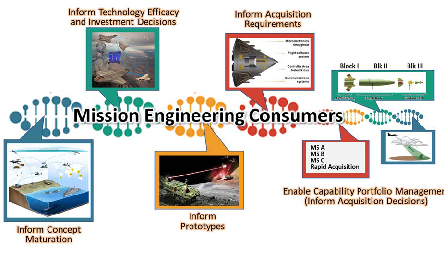
mission needs. Figure 1-1 illustrates the various consumers of ME products from concepts to
capability development to acquisition.
Figure1‐1.ConsumersofMissionEngineeringOutputs
ME uses validated mission definitions and trustworthy and curated data sets as the basis for
analyses to answer a set of operational or tactical questions. Shared assessments of conclusions
and understanding of analysis inputs helps leadership pursue the best course of action for decisions
in support of the warfighter and joint mission.
Key questions for the ME process include the following:
What is the mission?
What are its boundaries and how must it interact with other missions?
What are its performance measures?
1Introduction
MISSION ENGINEERING GUIDE
3
What are the mission capability gaps?
How can new capabilities change the way we fight?
What do changes in capabilities or systems mean to missions and architectures?
What is the sensitivity of the mission performance to the performance of the constituent
technology, products, and capabilities? How do the new capabilities best integrate with, or
replace, legacy systems? And how do we optimize that balance to provide the most lethal
and affordable integrated capabilities for any particular mission?
The major products from ME analyses include the following:
(1) Documented results in the form of analytical reports, curated data, and models for
continued reuse and further analysis;
(2) Visualizations and briefings to inform leadership on key decisions; and
(3) Government Reference Architectures (GRAs) (in the form of diagramed depictions of
missions and interactions among elements associated with missions and capabilities).
Together, these products identify and quantify mission capability gaps and help focus attention on
technological solutions to meet future mission needs, inform requirements, and support capability
portfolio management.
It is essential that ME analyses be consistent – both within themselves and with previous relevant
studies using the same scenarios, assumptions, constraints, system attributes, and data – curated
periodically or as necessary based on source updates. It is also essential to keep track of the sources
of data and the requirements used as inputs for the analysis.
Digital engineering principles should be used when conducting ME as they can help promote
consistency in the ME process through the effective use and reuse of curated data and models
along with identification and utilization of digital tools throughout ME analyses. Digital
engineering is an essential foundational element of ME that allows for sustainment of mission
threads (MTs) and architectures, integrated analytical capabilities, common mission
representations, and an extensible set of tools.
As illustrated in Figure 1-2, ME is a balancing act among the time frame, analytical rigor to be
used, and the complexity of the problem to be addressed. Reaching too far in one or more
dimensions, say predicting outcomes 50 years in the future or increasing the complexity of the
mission to be addressed, will impact the confidence-level that can be expected in the ME products.
It can also affect the rigor and validity of the analytics based on the availability and accessibility
of data.

1Introduction
M
ISSION
E
NGINEERING
G
UIDE
4
Figure1‐2.ThreeAxesofMissionEngineering

2MissionEngineeringApproachandMethodology
M
ISSION
E
NGINEERING
G
UIDE
5
2 MISSIONENGINEERINGAPPROACHANDMETHODOLOGY
ME is an analytical and data-driven approach to decompose and analyze the constituent parts of a
mission in order to identify measurable trade-offs and draw conclusions. Based on the question
asked, and the level of understanding of a given scenario and related contexts, an ME analysis
(part of a study) may hypothesize a new concept, system, technology, or tactics that may yield
superior “value” in a future military operation. The ME practitioner then designs an analytical
experiment to measure and compare the baseline approach to complete the mission to each
alternative case (also referred to as a trial case).
Since the number of contributing aspects of a mission is infinite, the majority of ME is an empirical
investigation. Therefore, to discover meaningful relationships between inputs and end effects, it
is critical for the practitioner to thoroughly document and fully understand: the definition of the
mission, underlying assumptions and constraints, the measures of mission success (metrics), and
source data used as inputs to the models. These elements are critical for quantitative analysis to
isolate the merits of the proposed approaches. As sufficient trials are conducted, mission drivers
may emerge to then form the basis of sensitivity analyses of specific parameters. For example,
isolating and changing just the speed of a weapon across many mission trials could be organized
to depict a sensitivity relationship of speed versus mission success.
As illustrated in Figure 2-1, the ME process begins with the end in mind, a carefully articulated
problem statement, the characterization of the mission and identification of metrics, and working
through the collection of data and models needed to analyze the mission and document the output
results.
Figure2‐1.MissionEngineeri ngApproachandMethodology
The problem statement, mission characterization, and mission metrics should be identified and
clearly understood ahead of time and documented. Developing a plan with this level of detail will
2MissionEngineeringApproachandMethodology
MISSION ENGINEERING GUIDE
6
greatly facilitate the execution of a thorough engineering analysis to explore outcomes of mission
approaches and support collaboration on subsequent recommendations.
2.1 ProblemStatement–IdentifyingtheKeyQuestions
To ensure the analysis is designed correctly, it is essential to initiate an ME study by articulating
the purpose and developing questions of interest to be answered. This information is key as it
drives other factors throughout the ME analysis such as identification of stakeholders, collection
of the appropriate data and models, and identification of meaningful and measurable metrics – all
of which will be used to obtain results that will inform significant decisions. When developing
questions, one should consider the following: What exactly do we want to find out? What do we
want to learn? What decisions is leadership seeking? Moreover, the problem statement should fully
articulate the mission or technology area of concern and desired answers that are being sought out.
Following are examples that can help guide practitioners to identify study questions:
What missions or concepts are we interested in exploring?
Which technology or capabilities are to be evaluated?
What mission capability gaps do we suspect/hypothesize?
What technologies, products, and capabilities support the mission?
What is assumed about the maturity, demonstration and fielding timelines for constituent
technologies, products, and capabilities?
How do the constituent products interact?
Are existing interfaces and standards for interaction adequate or are updates (or potentially
new standards) required?
Some specific study questions can be:
What is the optimal force mix of long-range fires?
What is the mission utility of using directed energy?
How can we optimally integrate emerging technology (i.e., Artificial Intelligence) into
mission threads?
2.2 MissionDefinitionandCharacterization
The mission definition and characterization provide the appropriate operational mission context
and assumptions to be used as the input of the analysis of the problem to be investigated. Whereas
the problem statement describes what we want to investigate, the mission definition and
2MissionEngineeringApproachandMethodology
MISSION ENGINEERING GUIDE
7
characterization describe both the entering conditions and boundaries such as the operational
environment and the commander’s desired intent or objectives for a particular mission.
For the ME analysis to be effective, the mission definition must be identical throughout all the
alternative approaches to be tried and evaluated. Once set, the mission definition should not
change throughout the ME analysis and should be included in all products resulting from the ME
method. Without this consistency, researchers cannot accurately compare the efficacy of the
options.
One can think of the mission definition and characterization as the stage for a play that addresses
the following information:
The Mission: Definition of the mission starts with defining the Commander’s Intent with
linkage to the National Defense Strategy, Defense Planning Guidance, Campaign Plan,
Combatant Command Operational Plan, Joint Warfighting Concept, or other similar
operational purpose documents that provide military functions, the geopolitical context of
operations, the overall definition(s) of mission success or mission objectives, or operational
stakeholder input. The grounding of the mission definition to these overarching planning
documents provides a consistent basis from which to derive necessary details of interest.
A critical element of the mission definition that should either be defined in the problem
statement or derived from the overall context of the planning documents is the time frame
of the intended operations (i.e., what year in the future are we going to investigate?).
Operational Environment: Linkage to Defense Planning Scenario or other military/DoD
references. The specific setup of the mission to include the detailed aspects of the mission
scenario and vignette(s) of interest that contain the geographic area, conflict, threat
laydown, red and blue forces, Order of Battle (OOB) and the overall rules of engagement.
Key references are the Concept of Operations (CONOPS) and Concept of Employment for
blue forces and adversary or red forces.
Operational Assumptions and Constraints (“Entering Conditions”): The assumed or
derived environmental conditions and resource or force limitations are stressors to the
context of the mission or of specific interest by stakeholders (e.g., contested environment,
weather, logistic constraints (e.g., no access to aircraft assets), stationary or moving targets,
and operational constraints [e.g., EMCON state]). Documenting these assumptions in an
organized manner is imperative to enable results from one ME study to be compared with
those of other ME studies, to enable future traceability when the analysis needs to be
updated, and to enable leadership to make accurate and informed decisions.
In defining the mission and problem space it is important to clearly separate the mission “what”
from the solution “how”. The goal of ME is to identify mission capability gaps and optimal

2MissionEngineeringApproachandMethodology
M
ISSION
E
NGINEERING
G
UIDE
8
solutions sets by fairly evaluating alternative mission execution concepts, variations, and trade
space. Overly constraining the mission definition will artificially influence potential solutions that
are not necessarily optimal.
As illustrated in Figure 2-2, a mission includes all the details necessary to frame the objectives,
operational environment, assumptions, and constraints that impact operational approaches and
systems to be used.
Figure2‐2.MissionCharacterization andMissionMetrics
TimeFrame
A critical element of the mission definition is the time frame for which a mission approach will be
evaluated. The time frame should reflect a particular year when the mission will take place. It
might be “present” day (today or current) or a “future” day (forthcoming time – near or distant).
Most likely the time frame will be grounded in a Multi-Service Force Deployment (MSFD) family
of scenarios that already define possible theater conflicts and challenge scenarios set in specific
planning time frames.
Since ME is focused on supporting investment decisions, using the predefined National Defense
Strategy, the Defense Planning Guidance, the National Military Strategy, MSFDs, and Future
Years Defense Program (FYDP) time frames are useful to provide consistency and enable trades

2MissionEngineeringApproachandMethodology
M
ISSION
E
NGINEERING
G
UIDE
9
between different missions set in the same time frame. The chosen time frame should be relevant
to the problem statement/hypothesis being answered or defended. For example, an acquisition
decision is likely to involve the system initial operational capability or final operational capability
time frames. Similarly, epoch technology changes may be set decades in the future. From a
specific time frame many other mission details can be derived, such as expected threat capabilities,
expected performance of blue forces, technology maturity, etc. Therefore, scenarios will have a
time frame associated with them since the adversaries’ capabilities continuously evolve and
change over time.
MissionScenariosandVignettes
Missions are hierarchical from strategic down to tactical. For the purposes of ME, we define two
broad categories of mission setups to help ensure the proper elements (or variables) are included
in the mission definition: scenarios and vignettes.
The scenario provides the overall context to the ME analysis and can be derived from the
Campaign Plan, Defense Planning Guidance, MSFD, or family of Joint Operations Concepts. It
provides the geographical location of operations and time frame of the overall conflict. It should
include information such as threat and friendly geopolitical contexts and backgrounds,
assumptions, constraints, limitations, strategic objectives, and other planning considerations. In
addition, the scenario will define and describe the overall mission objective or mission success
criteria of U.S. operations.
Vignettes represent a more narrowly framed subset of the scenario. There can be many vignettes
within a single scenario. A vignette could be thought of as a magnifying glass looking at just one
aspect of the scenario. The purpose of a vignette is to focus the analysis and the necessary detailed
information, such as the ordered set of events, behaviors, and interactions for a specific set of
systems. A vignette includes blue capabilities and red threats (threat laydown and expected
systems and capabilities of our adversaries) within an operational environment, as inputs or
variables to the analysis. Some ME analyses may seek answers at the campaign or mission level,
but this level of analysis can be accomplished only after the researchers understand and account
for the details of the vignettes.
The mission scenario and vignette should be properly selected and refined to match the needs of
the problem statement to ensure the analysis focuses on the questions and concerns of interest. It
is essential to be mindful of the chosen input parameters of the scenario as they will have varying
impact to the analysis results and outputs, for example, “the most likely, representative, real-
world” scenario versus “most” or “least” stressing scenario.

2MissionEngineeringApproachandMethodology
M
ISSION
E
NGINEERING
G
UIDE
10
Figure 2-3 shows the interdependencies among the mission definition, scenario, vignette, and
mission metrics (metrics are defined in Section 2.3 below). If the details of these key elements of
ME are not aligned to the questions of interest, then the results will not be suitable for the decision
the questions are intended to inform.
Figure2‐3.MissionDefinitionElementsandIden tifiedMetrics
AssumptionsandConstraints
An ME study should be carefully framed to address the problem under consideration. It is
appropriate at times to conduct a narrowly focused ME study in which practitioners want to control
all but a few limited variables. There may be inputs to the analysis that researchers do not
specifically know or for which they have no valid source, or due to limited resources and scope
the analysis may require bounding to a specific set of questions. It is very important practitioners
thoroughly document the assumptions and constraints.
Assumptions and constraints should be realistic and reasonable to ensure that one obtains useful
results. Assumptions and constraints can be made about the scenario or vignette that set the initial
conditions and mission context (e.g., operational, task activities, resources, OOB) or about the
performance characterization of the technologies, systems, or capabilities within the analysis.
Assumptions are constrained variables that otherwise could be allowed to be traded to set a
baseline from which to do analytical excursions when less than perfect data is available.
Clearly identifying the baseline assumptions and constraints may later help facilitate a sensitivity
analysis around the initial inputs and their impact on the results. For example, within an analysis
the definition for “contested environment” should be consistent across every approach under
consideration to ensure results can be compared. In such a case, the “contested environment”
might be defined as “no communications are available,” with each trial approach reflecting the
impact of this assumption.

2MissionEngineeringApproachandMethodology
M
ISSION
E
NGINEERING
G
UIDE
11
In summary, for any ME analysis, one must:
Identify and understand the assumptions, how they will be validated, and how they translate
into the variables that propagate through the analysis,
Identify and understand the limitations, such as constraints, that need to be considered,
Identify and elaborate on risks associated with assumptions and constraints, and
Identify and explore the areas of uncertainty in the mission definition.
MissionDefinitionSummary
The mission definition should be documented considering the categories listed in Table 2-1. This
table should serve as an outline of the information and special considerations that may be necessary
to scope the analysis or study.
Table2‐1.CategoriesofMissionDefinition
Linkageto“Strategic”Constructs
NationalDefenseStrategy(NDS)
DefensePlanningGuidance(DPG)
NationalMilitaryStrategy(NMS)
DefensePlanningScenario(DPS)
(StrategicScenario)
Multi‐ServiceForceDeployment(MSFD)
(OperationalScenarioderivedfrom
DPS)
MissionAreas
CampaignObjective
JointorServiceConceptofOperations
(CONOPS)andTactics,Techniques,and
Procedures(TTPs)
ScenarioandVignetteSpecifics
MissionSetting
Timeframe(year)
Phaseofconflict
Timeavailable
Theater/setting
Objective(s)andCommander’sIntent
Geopoliticalconsiderations
Environmental(contested,dust,weather,
terrain,day/night,weather,moon,solar,
etc.)
Allied,commercial,andneutralforces
Civilconsiderations
Threat(Red)Forces
Threats/capabilities/intel
BaselineforcesandOrderofBattle
(OOB)
ThreatCONOPS,RulesofEngagement
(ROE),doctrine,orTTPs
Blue(toincludecoalition)ForcesBaseline
Capability(intimeframeofinter est)
Systems/capabilities/performance
CONOPS,returnoninvestment,
doctrine,etc.
Baselineframeworkofoperationaltasks
MissionAssumptionsandConstraints
Performanceorcapabilitiesofsystems
ForceOOBanddeployment,movement
andsustainment(prepositioning);
logisticalconsiderations
Constituentsofthemissionand howit
mustinteractwithothermissionareas

2MissionEngineeringApproachandMethodology
M
ISSION
E
NGINEERING
G
UIDE
12
2.3 MissionMetrics(MeasuresofSuccessandEffectiveness)
Metrics are measures of quantitative assessment commonly used for assessing, comparing, and
tracking performance of the mission or system. Measurable outputs help commanders determine
what is or is not working and lend insights into how to better accomplish the mission. The ME
practitioner needs to identify a well-established set of metrics that can be used to evaluate the
completeness and efficacy of the components of mission-enabling activities. The mission metrics
represent the criteria that will be used to evaluate each of the alternative approaches in conducting
the mission.
Analytical documentation uses several similar terms to refer to mission metrics, including
Measures of Success, Measures of Suitability, Measures of Utility, Measures of Efficacy,
Measures of Effectiveness (MOEs), and Measures of Performance (MOPs). To simplify
terminology, this guide uses two broad categories of measures: MOE to indicate a measurable
attribute and target value for success within the overall mission; and MOP to indicate performance
characteristics of individual systems used to carry out the mission. Figure 2-4 illustrates the
relationship among types of measures.
Figure2‐4.RelationshipofMeasures
Mission efficacy is the ability to produce a desired result or effect and is measured through criteria
in the form of MOEs. MOEs help determine if a task is achieving its intended results. An MOE
is a criterion used to assess changes in system behavior, capability, or operational environment

2MissionEngineeringApproachandMethodology
MISSION ENGINEERING GUIDE
13
that is tied to measuring the attainment of an end state, achievement of an objective, or creation of
an effect.
MOEs help measure changes in conditions, both positive and negative, such as “Accomplish
without loss of a capital asset.” MOEs help to answer the question “Is the system doing the right
things?” Examples of MOEs for the objective to “Provide a safe and secure environment” may
include (1) Decrease in insurgent activity and (2) Increase in population trust of host-nation
security forces.
MOPs help measure the accomplishment of a system task. They answer questions such as “Was
an action taken?” or “Is the system doing things right?” MOPs will be discussed in relation to the
systems employed in an MT or Mission Engineering Thread (MET) which is discussed further
below in Paragraph 2.4.1.
For the purposes of this guide, an MOE is considered a function of contributing MOPs. Table 2-
2 provides examples of MOEs and MOPs that could be used in an ME analysis. Figure 2-5
provides examples in a hierarchical relationship.
Table2‐2.ExamplesofMOEsandMOPs
MOEsdefineadesirablemeasurableoutcomelinkedtotheobjective(Commander’sIntent)
ofthemission.Examples:
Number/percentageoftargetseffected(killed/disrupted/spoofed):goal70%
o Probabilityofkill
o Targetsheldatrisk
TimetoDefeatTarget:goallessthan90minutes
WeaponsRequiredtoDefeatTargets:goallessthan4
AssetsLost:goalminimize,lessthan10%
OperationalCostperTarg
etDestroyed:goal$100K/target
Posturefornextconflict:goalmaximize,50%offorcesdidnothavetomovefrom
pre‐conflictplacements
MOPsmeasurehowwellthemissionisaccomplished.Examples:
ProbabilitytoTrack
ProbabilitytoID
Range
Accuracyofweapon
Probablytoavoiddetection

2MissionEngineeringApproachandMethodology
M
ISSION
E
NGINEERING
G
UIDE
14
Figure2‐5.HierarchyExa mplesofMOEsandMOPs
SelectingMeasuresofEffectiveness
Starting with the overall objective(s) of a scenario or vignette in the mission definition, the mission
MOEs need to be defined in detail to answer the stakeholders’ questions of interest. The metrics
will vary depending on the level of analysis (i.e., campaign-level or mission-level).
For MOEs to be useful, they must be both quantifiable and relevant. A key tenet of ME is to
quantify the efficacy of alternative approaches in conducting a mission. As such, the MOEs should
reflect the Commander’s Intent and objectives and include measurable criteria to answer the
analysis or study questions. For example, a commander’s mission objective may be to disable a
truck convoy, and the quantifiable measures derived from that objective could be the number of
trucks destroyed or the probability of defeat/kill of a single truck.
MOEs should indicate the target value of success or favorable result (either threshold or objective).
Whenever possible, a range or specific value should be set for the goal. In addressing

2MissionEngineeringApproachandMethodology
M
ISSION
E
NGINEERING
G
UIDE
15
quantifiability, MOEs should address “win”-type measures (metrics to be maximized), “loss”-type
measures (metrics to be minimized or avoided), and ratios (comparison of two values or metrics).
For an MOE to be relevant, it must link clearly to the mission being analyzed. MOEs are based
on two main factors: (1) the top-down derivation from the problem statement through the mission
definition to represent the mission objective (i.e., Commander’s Intent) and (2) a bottom-up
explanation to characterize the constituent approaches and systems proposed to execute the
mission (red, blue, architecture, etc.) and associated availability of modeling and analytics.
The MOEs are closely linked to the MOPs in order to adequately reflect how the systems, systems-
of-systems, or capabilities are used to achieve the mission objectives. As depicted in Figure 2-6,
developing relevant MOEs is an iterative process that requires balancing the inputs of top-down
and bottom-up inputs to match the level of interest.
Figure2‐6.SuccessionofMeasures
While MOEs are specific to each scenario or vignette, several universal categories of MOEs could
be considered:
Mission satisfaction – achievement of end objective
Losses – loss of equipment, personnel, to adversary actions
Expenditures – consumables depleted during operations; for example, how many assets
used to relay a message or destroy a target.

2MissionEngineeringApproachandMethodology
M
ISSION
E
NGINEERING
G
UIDE
16
Cost (dollars) – a. cost of development of systems/technologies/concepts used in the
operational alternative, b. cost of operations
Time – duration of the mission operation
Repetition – number of mission passes to achieve acceptable mission satisfaction
Readiness – posture of forces to readily engage
Uncertainty – uncertainty in the above measures
Mission Return on Investment (ROI) – ratio of one metric / measure to another metric /
measure. Mission ROI evaluates the efficiency to achieve success to one or more different
MOEs, for example, the number of targets destroyed versus the number of assets expended.
ROI ratios are especially useful to help resolve cost-benefit efficacy based on type and
number of weapons used and the (amortized) cost of each. A primary purpose of
conducting an ME analysis is to inform the Planning, Programming, and Budgeting
Execution (PPBE) process. Cost type ROIs are useful to inform acquisition or technology
investment decisions either as a materiel or non-materiel solution.
TraceabilityofMetrics
It is natural for metrics to iteratively evolve as each of the alternative approaches are developed.
Useful measures emerge only when the questions to be answered, the mission (i.e., objectives),
and the activities, tasks, and systems under evaluation are understood. In ME the questions to be
answered are contained in the problem statement; however, the elements under evaluation, which
are initially extracted from the mission definition, can be further expanded and verified as one
designs the analysis (Paragraph 2.4) and develops the alternative (or trial) mission approaches (or
MTs or METs (as defined in Section 2.4.2)) to be assessed.
As each of the alternative approaches (varied systems) are developed and refined, one may revisit
the MOEs to ensure the selected measures are relevant to answer the study questions. Measures
should be selected to expose potential trades within the activities, tasks and systems of importance
to the overall mission objective. Figure 2-7 illustrates the lineage of metrics (i.e., MOEs and
MOPs) to MTs and METs (i.e., from tasks to functions to systems). This balance ensures that
good MOEs are being used in the analysis (as discussed in detail in Section 2.3.1 above).

2MissionEngineeringApproachandMethodology
M
ISSION
E
NGINEERING
G
UIDE
17
Figure2‐7.ExampleofMissionEngineeringThreadandAssociatedMOEsandMOPs
2.4 DesignofAnalysis
In its simplest form, ME analysis evaluates missions by examining the interaction between the
operational environment, threat, activities/tasks, and capabilities/systems used in current (today)
or future missions. The mission architecture represents the detailed structure of the conduct of the
mission. In all cases, the architecture is the means to fully document all mission elements in
relationship to other elements, the activities, threats, and the overall situational context.
Obtaining trustworthy data for the analysis and mission architecture is essential and should include
information from the mission definition (i.e., operational environment, threat laydown, red
characterization, etc.) as well as the blue force capabilities that are of primary interest to be
evaluated and linked to the questions to be answered. As shown in Figure 2-7, the end-to-end
sequence of blue activities/tasks can be depicted through an MT.
Once decomposed a level to include relevant systems and/or capabilities to execute end-to-end
missions, an MT is then referred to and depicted as a MET. These activities/tasks and
systems/capabilities can be varied to develop alternative approaches through runs and trials.
Furthermore, once MTs and METs are identified and sufficient data is collected, the appropriate
analysis is then conducted to obtain and document results to draw conclusions to answer the
problem. For ME purposes, this process is termed “design of analysis.”
MissionArchitectures
Mission architectures can be seen as “business models” for the conduct of the mission. As such,
the selected architecture must fit within larger constructs of the mission at the scenario, force

2MissionEngineeringApproachandMethodology
M
ISSION
E
NGINEERING
G
UIDE
18
deployment, and campaign levels. For each approach, the “As-Is” and the hypothetical “To-Be”
thread can be described in architectural terms (referred to simply as “views”) – Operational,
System and/or Technical View – of mission elements, showing the communication layers and
nodal linkages among each major element of a mission construct.
The methodical depiction of views and their relationships helps identify what data is needed, what
additional assumptions and constraints need to be made, and what models are appropriate for the
analysis. In this way, the mission architecture provides a thorough and methodical way of defining
the operations, systems, and data flow within the constraints of the scenario. As shown in Figure
2-8, a selected mission architecture depicts the detailed structure of the conduct of the mission. It
should include a series of interdependent views of the assets, organization, functions, interactions
and sequencing of the mission operations approach.
AMissionArchitectureisaconceptualmodelingofconce pts,approaches,andsystemsofsystemsthatenablesdetails
oftheprocessflow,timing,interactions,data,capabilities,andperformancetobeexaminedinrelationtotheother
processes,entities,andsystemsthatcontributetoachievingthemissionobjective.Itenablesorganizedinformation
sharingacrossthedepartment.
AMissionArchitecturecanaddressanoverallcampaignofmanyconcurrentprocessesandentitiesornarrowlyfocus
onjustoneentityandflow.
AMissionArchitectureisrepresentedbyaseriesof“views”toillustrate/highlightspecificdetails.Forexample,a
commonillustrationistheoperationaloverviewthatdepictsoverallin
tendedmilitaryoperationsofequipmentand
personnel.Anotherviewisthesequencedflowofeachtaskandactivitytoachievethoseoperations.Anotheristhe
schematicofinformationexchangestoenableandtriggerthosetasksandactivities.
Figure2‐8.TenetsofMissionArchitecture

2MissionEngineeringApproachandMethodology
M
ISSION
E
NGINEERING
G
UIDE
19
DefineMissionThreadandMissionEngineeringThread
A sub-element of mission architectures is an MT, which comprises the end-to-end tasks or
activities to accomplish a mission within a scenario or vignette. It can be simply referred as a
“mission approach.” It includes the tasks to be executed to conduct or carry out the mission to
satisfy a defined objective. Threads define the task execution sequence in a chain of events of how
systems, people, data, methods, tactics, timing, and interfaces will interact to complete necessary
tasks against threats and other variables to achieve mission objective(s). Examples of this end-to-
end mission construct are kill chains (kinetic) or effects chains (non-kinetic). There may be
multiple MTs linked over time to execute missions within a scenario or vignette. Figure 2-9 shows
how selected MTs can be seen as building blocks for the development of METs.
Figure2‐9.AnArchitectureofMissionThreads
As details associated with specific systems, technologies, or people are added, the generic MTs
become METs. This distinction between MT and MET is important because Joint Staff planning
documents have pre-defined generic MTs as planning constructs in the Universal Joint Task Lists
(UJTLs). In order to be useful for ME analysis, decomposition from MTs to METs and the lower-
level layer that maps systems to functions is needed.
Mission approaches should be constructed of narrative descriptions and architecture artifacts
(views) characterizing and defining the variables under study. This includes how operations are
executed today and hypothetical or future alternative approaches. It is important to identify the

2MissionEngineeringApproachandMethodology
M
ISSION
E
NGINEERING
G
UIDE
20
variables of interest to explore in the analysis, which can be derived from the problem statement
and the mission definition. Once the variables are identified, one can choose to change a single or
multiple variables to observe and explore the impact on the mission outputs.
The variables that can change are either tasks, capabilities, technology, or systems within a MT or
MET. By doing so, one is able to explore how the input variables impact and change the output
(mission success). Ideally, one would identify the most critical variable of interest engaged in
executing the mission to determine what works or not. The analysis should include approaches
that will output metrics that will be useful to answer the questions of interest. The problem
statement along with the specific details of the mission, scenario, and/or vignette (mission
characterization), will drive the inputs (i.e., tasks and/or systems) that will be varied across the
“alternative” approaches. The alternate mission approaches are driven by the specific trades in
capabilities, technology, tactics, systems, Doctrine, Organization, Training, Materiel, Leadership
and Education, Personnel, and Facilities (DOTMLPF), and concepts that are to be evaluated. This
helps lead to the ultimate goal – “How can we better accomplish and execute the mission?”
The “baseline” mission approach, commonly defined as the “As-Is” mission approach, represents
the current thinking as to the way to execute a mission within a given scenario and provides a
reference point for analysis and evaluation. Changes to the variables (i.e., systems, performance,
tactics, etc.) will lead to alternate approaches referred to as potential “To-Be” mission approaches
that are the alternate approaches to be evaluated. They do not account for changes in the
environment, threats, or scenario because those changes would require an entirely new mission
definition. As alternatives are evaluated and analyzed, the ME practitioner can identify a more
“optimal” approach that can be referred to as the “preferred” approach, which can form the new
reference for future analyses.
Note: The term “As-Is” does not necessarily mean the operations as they exist today; it is simply
a baseline from which to start the analysis.
DefineandGatherSupportingModels,Data,andAnalytics
ME is facilitated by the use of analytical and computational-based models that aid in the
representation of the operational and technical means to execute a mission. Use of models provides
for consistency and reuse of analytical constructs among ME practitioners. Crucially, ME
practitioners must take care to curate, or manage, the models they employ so that data elements,
hypothetical realizations, and assumptions are captured and archived with traceability to
authoritative sources.
Models should be constructed to include traceability of data, from concept through disposal. Per
DoD Modeling and Simulation standards and to understand all associated risks, practitioners

2MissionEngineeringApproachandMethodology
M
ISSION
E
NGINEERING
G
UIDE
21
should take care to specify that the models developed for the study support the specific intended
use of the analysis, undergoing a verification, validation, and accreditation process.
Models are not only traditional simulations, they also include mathematical representations, logical
expressions, and conceptual process steps or combinations of one or all of these elements. For
example, models or representations can be used to predict how a system might perform or survive
under various conditions or in various environments or how they might interact with one another
to conduct a mission. Models provide useful visualizations to support various analyses and studies
(e.g., trade space, sensitivity, gap, or military utility analyses).
Figure 2-10 represents examples of types of models that are developed, collected, integrated, and
used as part of ME.
Figure2‐10.ExampleModelsforUseinMissionEngineering
Thedigitalmodels thatsupportMEaredrivenbytherepresentationofdataandthe
typeofapproachmostsuitedtotheanalysis(i.e.,physics‐based,Monte‐Carlo).
Models vary in their levels of fidelity (i.e., “realism”) and in their associated uncertainties. ME
analyses need to determine which models should be brought together to answer analytic questions
and to balance the time, cost, and uncertainties in each study. ME stakeholders need to understand
and articulate the underlying fidelity and confidence in the chosen models to adequately determine
the impacts on the analysis and resulting decision-making process.
A model can be highly complex, and as a result, its relationships between inputs and outputs may
be poorly understood. In such cases, the model can be viewed as a black box, that is, the output is
an “opaque” function of its inputs. Often, some or all of the model inputs are subject to sources
of uncertainty, including errors of measurement, absence of information, and poor or partial
2MissionEngineeringApproachandMethodology
MISSION ENGINEERING GUIDE
22
understanding of the driving forces and mechanisms. This uncertainty imposes a limit on the
confidence in the response or output of the model. Analysis is required to minimize uncertainty
(discussed in the Analysis section, 2.5.1, below).
Model development, integration, use, analysis, and curation are core elements of ME activities.
The ME process, as described in Section 2.2, begins with a problem statement/analytic questions.
During the initial phase of the ME process, it is essential to determine what models, data and tools
already exist within the digital ecosystem. Additional considerations before commencing the study
include:
What domain(s) (Air, Surface, Subsurface, Space, Cyber, etc.) are involved in this study?
How much fidelity is required in the model to adequately respond to the problem
statement/analytic question?
What models are required to conduct the analysis? (e.g., 6-DOF, Physics-Based)
What models are already accessible? Do the required models already exist?
What is the pedigree of the model (verification, validation, accreditation, etc.)? Did we
build the right model for use?
The responses to these questions will trigger requests for additional models, data, tools, access to
other digital ecosystems, and updates to the ME digital ecosystem. When selecting models for the
ME process, it is essential to remember models are representations of reality. In the case of ME,
the reality may be an actual or conceptual system, or it may be the operational scenario in which
the system will participate.
ME activities are conducted within a digital ecosystem. The contents of the digital ecosystem
include:
Cyber-ready environment to include:
o Adequate computer power; if required, access to high-performance computing
o Multi-layer security; work space in unclassified, secret, and/or above secret
o Configurable/adaptable software framework
Access to models and data to include:
o Tools or software applications required for analytical or computational analyses
o Technical data (e.g., system performance, test results)
Hardware and software infrastructure to manage the ME process

2MissionEngineeringApproachandMethodology
M
ISSION
E
NGINEERING
G
UIDE
23
2.5 PerformAnalysis/RunModels
ME analysis includes evaluation of vignettes, mission threads in a vignette, or concepts across
vignettes/threads through analytical and computational means using data and models. The choice
of the most advantageous type of analysis will be driven by the problem statement, MET, and the
metrics of interest. The output may identify mission capability gaps and will provide metrics to
inform investment decisions in new capabilities or new ways to fight the future fight. Figure 2-11
(an extract of Figure 2-1) illustrates the methodology around the analytical design for ME.
Figure2‐11.MissionEngineeri ngAnalysis
InordertoconductMEanalyses,adequateandtrustworthy(validated)dataare
requiredtorepresentandmodelthemi ssionandsystems.
Below are items that the ME practitioner should take into consideration when identifying and
conducting the most appropriate analysis(es) for the study:
Identify the sensitivity analysis that should be performed. Understand sensitivity around
the baseline assumptions that influence the inputs and how they impact the outputs.
Address whether one needs to perform optimization and/or parametrization around the
assumptions or inputs.

2MissionEngineeringApproachandMethodology
M
ISSION
E
NGINEERING
G
UIDE
24
Determine the most applicable analytical methods. Examples include: simulation tools,
Monte Carlo analysis, Markov chain, regression analysis, cost/cost-benefit analysis, etc.
(Figure 2-12).
Identify and understand error and uncertainty propagation across the system of models.
o Track and measure error/confidence levels of data used in the analysis and results of
the analysis; understand fidelity of data and models
o Understand assumptions, approximations, models used, fidelity, etc.
Figure2‐12.Examples–TypesofAnalysis
Avarietyofanalysesmaybeuseddependingonthequestiontobeansweredandthe
desiredmetricsoroutputsrequired.Forexample,optimizationanalysiscanbeused
tofindtheoptimumvalueforoneormoretargetvariables,undercertainconstraints.
It is important to track the propagation of error and levels of confidence in findings against the
various metrics in all levels of analysis. Error and uncertainty can be introduced in an analytic
effort because of varying fidelities of models or the use of different types of models (parametric
versus statistical, for example). Among the most important tasks for an ME study team is to
understand the relationship among models, the input data (i.e., sources) to develop the models, and
the propagation of error throughout the analysis so the team can adequately define the confidence
level in the outputs/results.
In some instances, statistical analysis is a tool that practitioners can employ to determine
correlations between inputs and outputs. There are a number of methods (e.g., use of p-values) to
determine a threshold for statistical significance. Although threshold values may be subjective,
there are “generally accepted” values (e.g., a p-value of 0.05 or 5 percent probability of the result
being due to chance).
2MissionEngineeringApproachandMethodology
MISSION ENGINEERING GUIDE
25
Another method to determine confidence levels in results is performing a sensitivity analysis on
key baseline assumptions. Practitioners should consider employing sensitivity analysis to help
determine how different values of an input variable affect a particular output variable under a given
set of assumptions, identifying impacts on the MOEs or Measures of Success (MOS) of a mission.
Sensitivity analysis tests the robustness of the results of a model or equations in the presence of
uncertainty and reveals any first-order or second-order relationships between input and output
variables.
Sometimes an adequate sensitivity analysis can be performed by parametric means as opposed to
exercising a system of models. Using bounding case data (as in a case study) to drive the analysis
can provide insight into the solution space for a given analytical condition. Regardless of the
methodology, a properly designed sensitivity analysis will provide insight into the fidelity of the
results. Identifying the level of confidence in results is a key output for ME studies to help
leadership weigh the results of a given excursion or study against other factors when making
important decisions.
2.6 DocumenttheStudyandConclusions
As noted in the Introduction, the major products from an ME analysis include:
Documented results in an analysis report and decision briefing(s),
Reference or recommended mission architectures, and
Curated data models for reuse (as derived from the reference architecture).
These ME products and artifacts identify and quantify mission capability gaps and help focus
attention on technological solutions to meet future mission needs; inform requirements, prototypes,
and acquisition; and support capability portfolio management. They help explain the relational
attributes of an SoS vital to mission success.
It is important that the products of an analysis align with the original question(s) being asked and
highlight any need for extra work, or follow-on analysis. As a general rule, the outputs should
draw conclusions from study analysis and data outputs, discuss observed trends and implications,
and discuss relationships or correlations that can be made from the results. As such, these outputs,
discussed in more detail in the subsections below, form the basis for informing DoD leaders on
technology maturation plans, investment strategies, and preferred materiel solutions to close
warfighting capability gaps.

2MissionEngineeringApproachandMethodology
M
ISSION
E
NGINEERING
G
UIDE
26
AnalysisReport/DecisionalBriefings
The final analysis report and associated decisional briefing materials should discuss the overall
purpose of the analysis as defined by the stakeholders at the outset of the study. The report should
include the upfront planning (Problem, Mission Definition, Scenario and Vignette, MTs/METs,
Metrics, Design of Analysis, and Outputs) and should discuss what influenced or drove the
analysis framework, assumptions, and execution. Appendices A and B (Government Reference
Architectures) provide the recommended level of detail.
The report should accomplish the following:
Define the questions and mission
Define metrics for mission success – this can include MOEs
Identify threats and operational environment and source of information
Identify dependencies and impacts of mission/architecture on adjacent missions
Identify key assumptions about the mission, technology or capabilities
Explain the analytical methodology
Describe the architecture products
Explain the results obtained from the analysis
Identify any issues or uncertainties with the results
Discuss how the results apply to the problem statement
Describe the conclusions from the analysis
Recommend actions leadership or decision makers should take
Recommend further analysis or next steps
ReferenceArchitecture
The Reference Architecture (RA) depicts the preferred mission architecture resulting from the
analysis and describes the mission definition, assumptions, and constraints, methodology, levels
of confidence, uncertainty, and other analytical justifications to clearly convey the results. The
modifier “reference” highlights the one particular architecture that is preferred, based on the results
of the analysis. The RA and its justifying analysis should be thought of as an integrated product
and evolve from the analysis of one or more MTs/METs, which in turn are composed of
interdependent views of the mission. The use of architectures provides a way to explicitly compare
and contrast mission elements and attributes within and across many missions. For example, future

2MissionEngineeringApproachandMethodology
M
ISSION
E
NGINEERING
G
UIDE
27
technologies can be assessed across missions to reveal the value they provide and to inform
decisions regarding the priority of investments.
If the Government maintains ownership of the RA, this further designates it a Government
Reference Architecture (GRA). In ME, two other architecture terms should be defined:
Government Mission Reference Architecture (GMRA): Applicable to a single, end-to-
end mission; the preferred or selected architecture describing the MET.
Government Capability Reference Architecture (GCRA): Applicable to multiple
mission threads, optimizing common capabilities (functions or tasks) and attributes across
multiple METs; more narrowly focused on an enabling capability (e.g., seeking to optimize
a communications network to enable many METs).
Figure 2-13 shows the MET relationship between GMRAs and GCRAs. Appendices A and B
define the content and the applicability of each of the GRAs.
Figure2‐13.IntegrationandTradesofMissionThreadsandCapabilities
GovernmentReferenceArchitecturesareusedtoconveyresultsdepictingthe
capabilitiesrequiredtomeetmission objectives.Twotypesoflinked and“cross‐
cutting”architecturesare“Capability”and“Mission”ReferenceArchitectures.

2MissionEngineeringApproachandMethodology
M
ISSION
E
NGINEERING
G
UIDE
28
CuratedData,Models,andArchitectures
As analyses are developed and completed, the data, models, and architectures need to be properly
collected and organized to be preserved, shared, and discovered for future analyses. For the
purposes of ME, the term “data” means information related to the scenario or vignette, OOB, force
structure, system parameters or performance, threat, models, and analytical results. Data are the
“building blocks” and “backbone” behind models, MTs/METs, and GRAs.
It is incumbent upon each ME practitioner to curate data to ensure the value of the data is
maintained over time, and the data remains available for reuse and preservation. Risks of poor or
no data curation include factually inaccurate information, incorrect guidelines, and knowledge
gaps. As technology or capability design and development mature and systems are tested and
evaluated in exercises and experimentation, one collects valuable data that provides a more
trustworthy representation of system performance and capability development efforts. ME
practitioners should make sure there is a “feedback” mechanism to use this data to redo or repeat
their analysis to identify whether the developed technology or capability has a positive or negative
impact on the mission objectives (MOEs), whether it truly closes mission capability gaps, or if it
changes the mission architecture(s) or assumptions used in the analysis. This feedback allows ME
to be a repeatable process that outputs more reliable results.
Initially, the curation and standardization of data will be based on collaboration with immediate
peer analysts in answering immediate reuse questions: How should one label and organize the
data and the results to best facilitate the next analysis? As ME evolves, cross-Service working
groups, OSD, and Joint Staff will publish more rigorous guidelines. While some general rules and
best practices apply, the data curator must make an educated decision about which data assets are
appropriate to use. At a minimum the following should be addressed for all data used or generated:
Timeliness: When was the data last updated?
Lineage: Where did the data come from? Source?
Validity: How confident are we in the quality of the data?
Accuracy: Is the data complete and how does it match agreed-upon definitions?
Linkage: How was the data generated, converted, or collected? To what ME use was it
associated?
Profile: How would one catalogue the data to retrieve it later – to what other ME data is it
topically associated?

AppendixA:GMRATemplate
MISSION ENGINEERING GUIDE
29
AppendixA:GovernmentMissionReferenceArchitecture(GMRA)(Template)
Purpose
Government Mission Reference Architectures (GMRAs) should be used to guide and constrain
systems of systems that are required to carry out an operational or tactical mission.
Definitions
Mission: a set of objectives and goals to be achieved in a specific operational environment.
Examples include Time-Sensitive Target, Close Air Support, Suppression of Enemy Air Defenses,
Air Refueling, or Undersea Warfare.
Architecture: a unifying or coherent form or structure of components and either relationships;
simply a depiction or view.
Mission Thread: synonymous with “mission architecture,” a coherent form or structure of activities
or systems to execute an end-to-end mission. The mission thread or mission architecture shows
the components and tasks and their relationships.
Government Reference Architecture: a Government-owned, authoritative source of information
about a specific subject area that guides and constrains the instantiations of multiple mission
architectures and solutions.
Outline
Executive Summary
Include the title of the mission.
Include a brief overview of the mission to include scenario, the origin of the mission
requirement and supporting reference documents, a description of the proposed mission
architecture, key assumptions and the sensitivity analysis around those assumptions.
Outline potential next steps for implementation.
Identify owner/configuration manager; discuss the update cycle and decision points/events
that may drive an update to the GMRA.
Mission Definition
Describe the mission.
o Define the mission objectives
o Explain the overall concepts of operations and employment
AppendixA:GMRATemplate
MISSION ENGINEERING GUIDE
30
o Include time frame, domain, theater or other details as needed
o Describe the scenario
o Identify the Mission Threads and/or Mission Engineering Threads
Include activities/tasks and/or systems
Identify the stakeholders for the mission.
o For example: Services, Agencies, allies that are part of the mission; depending on the
mission, there may be other integral non-traditional organizations
Define metrics for mission success, including Measures of Effectiveness (MOE).
Identify relevant family of Joint Operations Concepts or Commander’s Intent (if
applicable).
o List specific concepts, such as the Joint Warfighting Concept (JWC), that are being
used to define the mission
Foundational Assumptions and Dependencies
Identify threats and operational environment and source of information.
Identify dependencies and impacts of mission/architecture on adjacent missions (GMRAs).
Identify key assumptions about the mission, technology or capabilities.
o Explain how the study team determined these assumptions and why they are realistic /
reasonable
Describe assumptions with variables, if applicable
Analytical Methodology
Describe the analytical and computational tools used, including the type of methods (e.g.,
parametric, probabilistic, physics based, subject matter expert, table-top).
Describe the models used, identify pedigree and fidelity.
Identify the data collected and used to populate the models and include source.
Describe the integrated uncertainties across the whole modeling environment and impact
on the precision/accuracy of the answer.
Define trade space analysis – What parameters or variables were held constant and which
ones changed.
Explain the sensitivity analysis around the baseline assumptions.
Include cost analysis techniques/methods, if appropriate.
Perform gap analysis to determine if there are any issues or risks to obtain mission success.
AppendixA:GMRATemplate
MISSION ENGINEERING GUIDE
31
Architecture Overview
Describe the architecture products that guide and constrain the GMRA.
o Describe the As-is state of the mission and the To-be state of the mission
o Depict gaps within the architecture
o Include an OV-1 view if applicable; this can be depicted as a Mission Thread or
Mission Engineering Thread
o List the components and their technical and performance attributes
Include how the components or systems are interfaced/communicate with one
another
o Discuss trades or alternatives (related to sensitivity analysis/uncertainties)
Identify capability solutions that can close mission capability gaps
Conclusions
Describe the GMRA metrics for success.
o Explain the results obtained from the analysis
o Identify any issues or uncertainties with the results
Identify next steps required to instantiate the GMRA.
Identify any recommended follow-on studies.

AppendixB:GCRATemplate
MISSION ENGINEERING GUIDE
32
AppendixB:GovernmentCapabilityReferenceArchitecture(GCRA)(Template)
Purpose
Government Capability Reference Architectures (GCRAs) should be used to guide and constrain
a set of common capabilities within a specific domain (e.g., Space, Electromagnetic Spectrum,
Cyberspace) or technical functions and processes (e.g., Command and Control, Communications
or Positioning, Navigation, and Timing). These capabilities, either domain specific or by technical
functions/processes, will be required to carry out multiple operational or tactical missions. GCRAs
will depict the current and future architecture to determine where mission capability gaps exist and
guide future investment decisions for new game-changing capabilities to ensure the United States
can counter or outmatch adversaries in the future fight. Warfighters require capabilities that
operate in the mildest to extreme operational environment (low to highly contested environments).
The threat will continuously change, therefore the GCRA must be able to be updated based on the
scenarios and evolving threat.
Definitions
Architecture: a unifying or coherent form or structure of components and either relationships;
simply a depiction or view. For the purpose of a GCRA, the architecture shows the current and
future set of mission or capabilities and their design and evolution over time.
Capability Architecture: a unifying or coherent form or structure depicting the various capability
options/alternatives to include components, relationships, and principles.
Government Reference Architecture: a Government-owned, authoritative source of information
about a specific subject area that guides and constrains the instantiations of capability architectures
and solutions.
Outline
Executive Summary
Include a brief overview of the Capability Area that the GCRA describes.
o Include background on the purpose of the GRA, list of the various missions used to
inform the development of the GCRA, key assumptions, and other reference documents
Describe overall Concept of Operations of the GCRA.
Outline potential next steps for implementation.
Identify owner/configuration manager; discuss the update cycle and decision.
points/events that may drive an update the GCRA.
AppendixB:GCRATemplate
MISSION ENGINEERING GUIDE
33
Capability Area Definition
Describe the Capability Area.
o Define the objective
o Explain the overall context of operations and employment
o Include the time frame, domain, theater, or other details as needed
o Describe the scenario
o Define or reference all missions analyzed in creating the GCRA
Identify the Mission Threads and/or Mission Engineering Threads.
o Include activities/tasks and/or systems
Identify the stakeholders.
o For example: Services, Agencies, allies that are part of the mission. Depending on the
mission, there may be other non-traditional organizations integral to the mission.
Define metrics for mission success – this can include mission Measures of Effectiveness
(MOE).
Foundational Assumptions and Dependencies
Identify threats and mission environments and source of definition.
Identify dependencies and impacts of capability architecture (GCRA) to various missions
(GMRAs).
Identify key assumptions about the missions, technologies, or capabilities.
o Explain how the analysts determined these assumptions and why the assumptions are
realistic/reasonable
Describe assumptions with variables if applicable.
Analytical Methodology
Describe the analytical and computational tools used, including the type of methods (e.g.,
parametric, probabilistic, physics based, subject matter expert, table-top).
Describe the models used, identify pedigree, and fidelity.
Identify the data collected and used to populate the models, include source.
Describe the integrated uncertainties across the whole modeling environment and impact
on the precision/accuracy of the answer.
Define trade space analysis – what parameters or variables were held constant and which
ones changed.
Explain the sensitivity analysis around the baseline assumptions.
Include cost analysis techniques/methods, if appropriate.

AppendixB:GCRATemplate
MISSION ENGINEERING GUIDE
34
Perform gap analysis to determine if there are any issues or risks to obtain mission
success.
Architecture Overview
Describe the architecture products that guide and constrain the GCRA.
o Describe the As-Is state of the capability architecture and the To-Be state of the
capability architecture
o Include the list of capabilities and their technical and performance attributes
o Describe the technology readiness level, agency responsible for each
capability/technology, and planned deployment date
Describe the approach to mature or develop each capability, system, technology, etc.
Describe the risks associated with each of the capabilities.
o Risks can be associated with data exchange, interoperability, system performance
against threat or in operating environment(s), schedule
The following table shows notional GCRA artifacts:
o NOTE: Department of Defense Architecture Framework (DoDAF) products are used
only to illustrate EXAMPLES of the various architecture artifacts that may be required
for a GCRA
Example GCRA Artifacts
Content ExampleViews/Models
Purpose:Introduction,overview,
context,scope,goals,purpose,why
needed,andwhenandhowused
•
AV‐1Overview&SummaryInformation
•
CV‐1:Vision–overallstrategicconceptandhighlevelscope
•
OV‐1HighLevelOperationalConceptGraphic–executiveoperationalsummarylevel
ofwhatthepreferredalternative(solution)architecturesareintendedtodoand
howtheyaresupposedtodoit
TechnicalPositions&Policies
•
StdV‐1StandardsProfile–standards,specifications,guidance,policyapplyingto
elementsofthepreferredalternative(solution)architectures
ArchitecturalPatterns:generalized
patternsofactivities,andsystem
functionalityandtheirresources,
providersandinformation/data
resourceflows
Generalizedscenariopatternsof
sequenced(sequential/concurrent)
responsesbyactivities,servicesand
systemfunctions(togetherwiththeir
resources)tosynchronous/
asynchronoustimedevents
OperationalPatterns
•
OV‐2(multiple)OperationalResource
Flows
•
OV‐5{a,b}Activitydiagrams
•
OV‐6cEvent‐TraceDescription
SystemPatterns
•
SV‐1(multiple)System
Interfaces
•
SV‐2SystemResourceFlows
•
SV‐4SystemFunctionality
•
SV‐10bSystemState
Transitions
•
SV‐10cSystemsEvent‐Trace
Description
Event‐BasedScenarioPatternsofDynamicBehavior
•
OV‐6cEvent‐TraceDescription
•
SvcV‐10cServicesEvent‐TraceDescription
•
SV‐10cSystemsEvent‐TraceDescription
AppendixB:GCRATemplate
MISSION ENGINEERING GUIDE
35
Conclusions
Describe the GCRA metrics for success.
o Explain the results obtained from the analysis
o Identify any issues or uncertainties with the results
Identify next steps required to instantiate GCRA.
Identify any recommended follow on studies.
Method to Evaluate Completeness and Quality of a GRA
This section provides more open-ended evaluation criteria for the practitioner and is intended to
prompt the development of measures of effectiveness/measures of performance by which the GRA
should be assessed.
The GRA should be a tool, forming a baseline structure that can be applied to various analyses
under a given scenario, to assess their efficacy. As such, the ME practitioner should apply some
general measures of effectiveness to evaluate (1) the quality of the GRA, as such, and (2) the
validity relevance of the GRA to the scenario under analysis.
Does the GRA address both functional and operational constituents?
Does the GRA describe the scenario, time frame, operational environment, and threat?
Is there a clear and documented set of artifacts that describe the requirements (e.g.,
interface requirements, data exchange requirements) that the Government Reference
Architecture satisfies?
Is there a clear and documented architecture model which describes both functional and
infrastructure components and their relationships?
Does the architecture describe how components would be built to realize services and their
operations?
Does the Government Reference Architecture provide quantified measures to guide design,
selection, and development of materiel solutions?
Are there clear steps that identify how to instantiate Government Reference Architecture
and whether additional analysis or studies are required?
Definitions
MISSION ENGINEERING GUIDE
36
Definitions
Architecture – The structure of components, their relationships, and the principles and guidelines
governing their design and evolution over time. (DAU Glossary)
Assumption – A specific supposition of the operational environment that is assumed to be true, in
the absence of positive proof, essential for the continuation of planning. (JP 5-0, DoD Dictionary)
Baseline – An integrated set of data used by the DoD Components as an agreed upon starting point
for studies supporting the development and implementation of defense strategy and DoD (PPBES)
activities. Baselines are produced and reviewed in an open, collaborative, and transparent
environment. (DoDD 8260.05)
Capability – The ability to complete a task or execute a course of action under specified conditions
and level of performance. (CJCSI 5123.01H, DAU Glossary)
Concept of Operations (CONOPS) – A verbal or graphic statement that clearly and concisely
expresses what the commander intends to accomplish and how it will be done using available
resources. Also called CONOPS. (JP 5-0, DoD Dictionary)
Constraint – In the context of planning, a requirement placed on the command by a higher
command that dictates an action, thus restricting freedom of action. (JP 5-0; DoD Dictionary)
Experiment – In context of ME, future-oriented testing of proposed solutions to evaluate their
ability to enable preferred ways of operating in the anticipated future operating environment.
(“Guide for Understanding and Implementing Defense Experimentation,” 2006; CJCSI 3030.01)
Fidelity – The degree to which a model or simulation represents the state and behavior of a real
world object or the perception of a real world object, feature, condition, or chosen standard in a
measurable or perceivable manner; a measure of the realism of a model or simulation. (Defense
Modeling and Simulation Coordination Office M&S Glossary)
Government Reference Architecture (GRA) – Government-owned Reference Architectures; the
authoritative [Government] source of information to guide and constrain mission architectures and
solutions. It integrates the data, information, boundary conditions and rules that describe the
mission capability needed by the warfighter in sufficient detail to allow for transition of
technology-based solutions. (ME Guide)
Kill Chain – Mission thread with a kinetic outcome. Dynamic targeting procedures, often referred
to as find, fix, target, track, engage, assess (F2T2EA) by air and maritime component forces;
decide, detect, deliver, and assess methodology by land component forces. (JP 3-09)
Mission – 1. The task, together with the purpose, that clearly indicates the action to be taken and
the reason therefore. (JP 3-0) 2. In common usage, especially when applied to lower military
units, a duty assigned to an individual or unit; a task. (JP 3-0) 3. The dispatching of one or more
aircraft to accomplish one particular task. (JP 3-30). (DoD Dictionary)
Definitions
MISSION ENGINEERING GUIDE
37
Mission Approach, “As-Is” – The “as-is” mission approach represents the baseline reference
case to which comparisons of alternatives will be evaluated. (ME Guide)
Mission Approach, “To-Be” – The “to-be” mission approaches are the many alternate approaches
being evaluated; these account for changes in systems, performance, tactics, etc. They do not
account for changes in the environment, threats, scenario, etc. Those changes would require an
entirely new mission definition. (ME Guide)
Mission Architecture – The detailed structure of the conduct of the mission. A series of
interdependent views of the assets, organization, functions, Interactions and sequencing of the
mission operations approach. The mission architecture is a “business” model of the conduct of the
mission vignette and must fit within lager constructs of the mission at the scenario, force
deployment and campaign levels. (ME Guide)
Mission Capability Gap – The inability to execute, carry out, or complete a specified mission.
The gap may be the result of no current or existing capability, a lack of proficiency or sufficiency
in a current or existing capability, or the need to replace an existing capability to prevent a future
gap such as interoperability. (Adapted from CJCSI 3010.02E)
Mission Definition – The elements that describe the context of the mission. The definition of the
mission to be accomplished in a specific time frame, its success factors, the threats and constraints
(environment, socio-political, allies/enemies/neutrals, etc.). Changes in any of the components of
a mission create a new mission definition. (ME Guide)
Mission Efficacy – The ability to produce the desired or intended result of the operational
approach. (ME Guide)
Mission Element – A platform or system that performs a task; a combination of platform, system
and/or subsystems that provides a functional performance using specific technical characteristics
to perform a specific task. (ME Guide)
Mission Engineering (ME) – The deliberate planning, analyzing, organizing, and integrating of
current and emerging operational and system capabilities to achieve desired warfighting mission
effects. (DAG Chapter 3/FY 2017 NDAA Section 855 Report to Congress)
Mission Engineering Thread (MET) – Mission threads that include the technical details of the
capabilities and systems required to execute the mission. (ME Guide)
Mission Integration Management (MIM) – The management, synchronization, and coordination
of concepts, activities, technologies, requirements, programs, and budget plans to guide key
decisions focused on the end-to-end mission. (ME Guide)
[Mission] Return on Investment (ROI) – An evaluation of the cost incurred against the benefits
realized. Evaluating the ROI of MS&A in such roles involves weighing the costs against the
benefits. Costs include the construction, operation, and maintenance of [mission] capabilities.
Benefits include time savings, improved training, and safety [and qualitative or quantitative
measures of mission success -- e.g., target(s) destroyed]. (National Research Council 2006.
Definitions
MISSION ENGINEERING GUIDE
38
Defense Modeling, Simulation, and Analysis: Meeting the Challenge. Washington, DC: The
National Academies Press. https://doi.org/10.17226/11726.)
Mission Tasks – A clearly defined action or activity specifically assigned to a system, individual
or organization that must be done. (Adapted from JP-01).
Mission Thread (MT) – A sequence of end-to-end activities and events presented as a series of
steps to achieve a mission. (ME Guide)
Model – A primarily quantitative or computational system employing mathematical equations that
specify parametric relationships and their associated parameter values as a function of time, space,
and/or other system parameters. (A Practical Guide to SysML (Third Edition))
Operations – 1. A sequence of tactical actions with a common purpose or unifying theme. (JP 1)
2. A military action or the carrying out of a strategic, operational, tactical, service, training, or
administrative military mission. (JP 3-0, DoD Dictionary) There are operations - sequences of
tactical actions with a common purpose or unifying theme; major operations - series of tactical
actions to achieve strategic or operational objectives; and campaigns - series of related major
operations aimed at achieving strategic and operational objectives within a given time and space.
(JP-1)
Reference Architecture (RA) – An authoritative source of information about a specific subject
area that guides and constrains the instantiations of multiple architectures and solutions (DoD
Reference Architecture, June 2010)
Scenario – Description of the geographical location and time frame of the overall conflict. It
should include information such as threat and friendly politico-military contexts and backgrounds,
assumptions, constraints, limitations, strategic objectives, and other planning considerations. (ME
Guide)
Sensitivity Analysis – Determines how different values of an independent variable affect a
particular dependent variable under a given set of assumptions. (Investopedia)
Strategic – In the context of national interests, the level at which national, multinational, and
theater objectives are addressed. (Adapted from JP 3-0, Chapter 1, 6.b.)
Tactical – The level of employment, ordered arrangement, and directed actions of forces in
relation to each other, to achieve military objectives assigned to tactical units or task forces (TFs).
(Adapted from JP 3-0, Chapter 1, 6.d.)
Threat – The sum of the potential strengths, capabilities, and strategic objectives of any adversary
that can limit U.S. mission accomplishment or reduce force, system, or equipment effectiveness.
It does not include (a) natural or environmental factors affecting the ability or the system to
function or support mission accomplishment, (b) mechanical or component failure affecting
mission accomplishment unless caused by adversary action, or (c) program issues related to
budgeting, restructuring, or cancellation of a program. (DAU Glossary, CJCSI 5123.01H)
Definitions
MISSION ENGINEERING GUIDE
39
Verification – The process of determining that a model or simulation implementation and its
associated data accurately represent the developer's conceptual description and specifications. (JP
3-13.1, DoD Dictionary)
Validation – The process of determining the degree to which a model or simulation and its
associated data are an accurate representation of the real world from the perspective of the intended
uses of the model. Applicable to an expressed user need and consistent with program concept of
operations. (SMC Mission Engineering Primer and Handbook)
Vignette – A narrow and specific ordered set of events, and behaviors and interactions for a
specific set of systems to include blue capabilities and red threats within the operational
environment. Vignettes can represent small, ideally self-contained parts of a scenario. (ME
Guide)
Acronyms
MISSION ENGINEERING GUIDE
40
Acronyms
CONOPs Concept of Operations
DOTMLPF
Doctrine, Organization, Training, Materiel, Leadership and Education,
Personnel, and Facilities
DoD Department of Defense
DPG Defense Planning Guidance
DODAF Department of Defense Architecture Framework
FYDP Future Years Defense Program
GCRA Government Capability Reference Architecture
GMRA Government Mission Reference Architecture
GRA Government Reference Architecture
ME Mission Engineering
MET Mission Engineering Thread
MOE Measure of Effectiveness
MOP Measure of Performance
MOS Measure of Success
MSFD Multi-Service Force Deployment
MT Mission Thread
NDS National Defense Strategy
NMS National Military Strategy
OOB Order of Battle
OSD Office of the Secretary of Defense
PPBE Planning, Programming, and Budgeting Execution
RA Reference Architecture
ROI Return on Investment
TTP Tactics, Techniques, and Procedures
UJTL Universal Joint Task Lists
USD(R&E) Under Secretary of Defense for Research and Engineering
References
MISSION ENGINEERING GUIDE
41
References
CJCSI 3030.01, Implementing Joint Force Development and Design, December 3, 2019.
CJCSI 5123.01H, Charter of the Joint Requirements Oversight Council (JROC) of the Joint
Capabilities Integration and Development System (JCIDS), August 31, 2018.
Defense Acquisition Guidebook (DAG), Chapter 3, Systems Engineering, Defense Acquisition
University.
https://www.dau.edu/tools/dag
Defense Acquisition University (DAU) Glossary.
https://www.dau.edu/tools/t/DAU-Glossary
Defense Modeling and Simulation Coordination Office (DMSCO) M&S Glossary.
https://www.msco.mil/MSReferences/Glossary/MSGlossary.aspx
DoD Dictionary of Military and Associated Terms, June 2020.
https://www.jcs.mil/Portals/36/Documents/Doctrine/pubs/dictionary.pdf
DoD Digital Engineering Strategy, Office of the Under Secretary of Defense for Research and
Engineering, June 2018.
DoD Directive 5135.02, “Under Secretary of Defense for Acquisition and Sustainment
(USD(A&S)),” July 15, 2020.
DoD Directive 5137.02, “Under Secretary of Defense for Research and Engineering
(USD(R&E)),” July 15, 2020.
DoD Directive 8260.05, “Support of Strategic Analysis (SSA),” July 7, 2011.
DoD Instruction 5000.UJ, “Engineering of Defense Systems,” Forthcoming.
DoD Reference Architecture Description, Office of the Assistant Secretary of Defense, Networks
and Information Integration (OASD/NII), 2010. Accessed November 5, 2020.
http://www.acqnotes.com/Attachments/Reference%20Architecture%20Description,%20June
%202010.pdf
Friedenthal, S., A. Moore, and R. Steiner. A Practical Guide to SysML, 3rd Edition. Waltham,
MA: Elsevier/Morgan Kaufmann, 2014.
Guide for Understanding and Implementing Defense Experimentation (GUIDEx), The Technical
Cooperation Program, Version 1.1, February 2006.
Investopedia.
https://www.investopedia.com/terms/s/sensitivityanalysis.asp
Joint Publication 1, Doctrine for the Armed Forces of the United States, March 25, 2013,
Incorporating Change 1, July 12, 2017.
Joint Publication 3-09, Joint Fire Support, April 10, 2019.
Joint Publication 3-30, Joint Air Operations, July 25, 2019.
Joint Publication 3-85, Joint Electromagnetic Spectrum Operations, May 22, 2020.
Joint Publication 5-0, Joint Planning, June 16, 2017.
References
MISSION ENGINEERING GUIDE
42
“Mission Integration Management.” Report to Congress in response to National Defense
Authorization Act for Fiscal Year 2017, Section 855. Office of the Under Secretary of
Defense for Acquisition, Technology, and Logistics, March 2018.
National Defense Authorization Act for Fiscal Year 2017, Public Law 114-328, 114th Congress,
December 23, 2016.
National Research Council. Defense Modeling, Simulation, and Analysis: Meeting the
Challenge. Washington, DC: The National Academies Press, 2006.
https://doi.org/10.17226/11726
Space and Missile Systems Center (SMC) Systems Engineering Primer & Handbook, 2nd
Edition. Los Angeles Air Force Base, El Segundo, CA: SMC, U.S. Air Force, 2004.
http://www.acqnotes.com/Attachments/SMC%20System%20Engineering%20Handbook.pdf,
last accessed November 5, 2020.
Mission Engineering Guide
Of
fice of the Under Secretary of Defense for Research and Engineering
3030 Defense Pentagon
Washington, DC 20301
https://ac.cto.mil/engineering
Distribution Statement A. Approved for public release. Distribution is unlimited.
